

Page 1
Motor Control Hub PC Board [002-1749-00]
midmark.com
WARNING
Always disconnect chair from power source before removing
any covers. Failure to do so may result in personal injury.
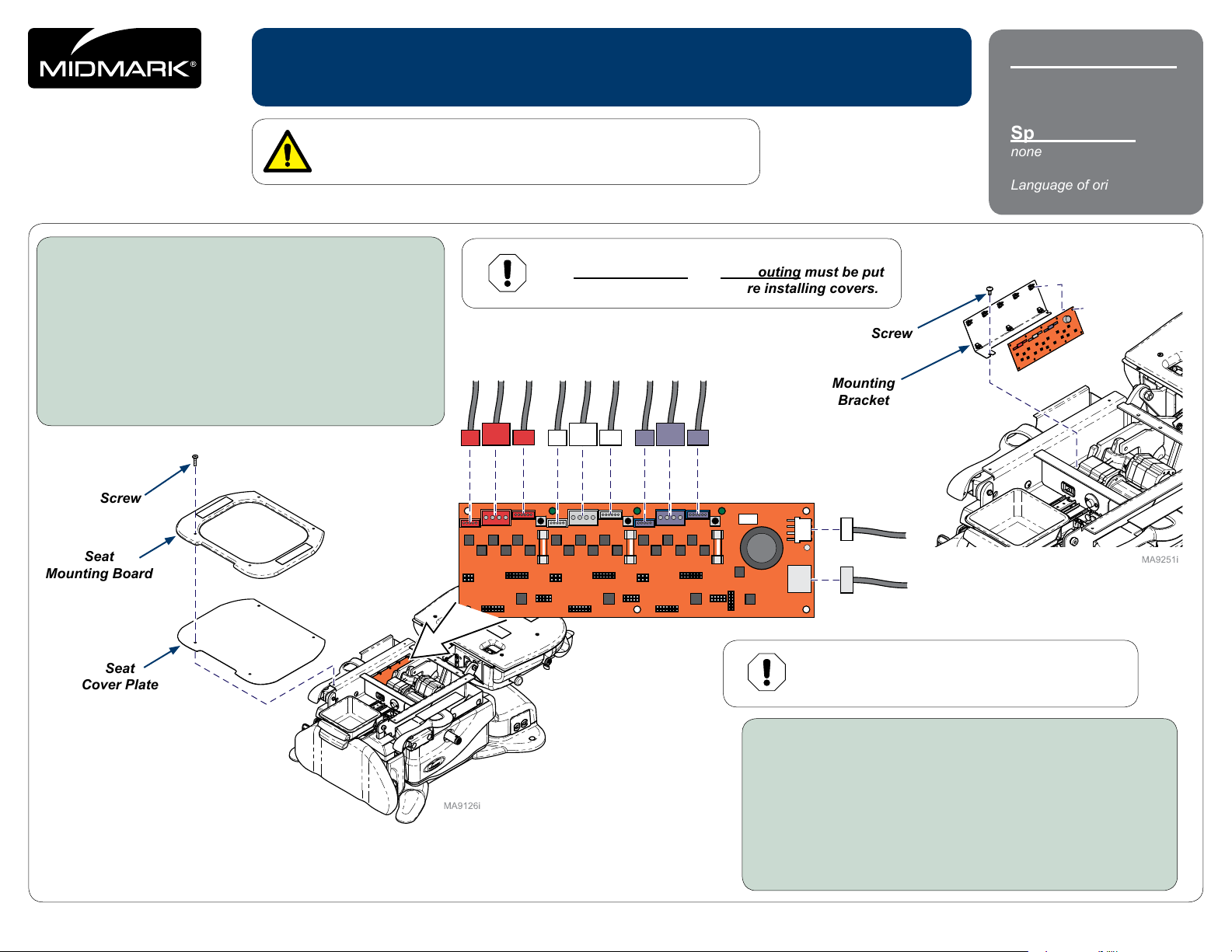
To remove Motor Control Hub PC Board...
A) Remove seat / back upholstery.
B) Remove four screws, seat mounting board,
and seat cover plate.
C) Disconnect wiring from PC Board.
D) Remove two screws and mounting bracket.
E) Remove PC Board.
Note: Push latches back, then lift PC Board off of mounting studs.
Applies to Models:
630 (-010 thru -013)
630 (-020 thru -023)
Special Tools:
none
Language of origin: English
Equipment Alert
The wire connections and wire routing must be put
back in original locations before installing covers.
Screw
Mounting
Bracket
Screw
Seat
Mounting Board
Seat
Cover Plate
© 2014 Midmark Corp. | 60 Vista Drive Versailles, OH 45380 USA | 1-800-643-6275 | 1-937-526-3662 |
J13
J15
J14
TPA
J9
J11
TPB1
TPB2
J12
F3
TPB3
J2
TPD2
J1
TPD1
J6
F1
TPD3
J4
J3
J5
J7
TPC1
TPC2
J8
J10
F2
TPC3
Equipment Alert
Anytime the limit switch wires or the actuator wires
are disconnected, the chair must be calibrated.
To install Motor Control Hub PC Board...
A) Install PC Board onto mounting bracket.
B) Position mounting bracket and secure with two screws.
C) Connect wiring to PC Board.
D) Calibrate chair.
E) Position seat cover plate, and seat mounting board,
then secure with four screws.
F) Install upholstery.
English-1
Style G
003-2717-00 Rev. AA1 (10/29/18)
Page 2
J2
midmark.com
Calibration Procedure
During the calibration procedure you will hear a steady pattern of “beeps” .
The chair will run all functions (base, back, tilt, foot) to their minimum and maximum positions,
then return to a lowered at position.
When calibration is complete, the chair will stop moving and you will hear three short “beeps”.
You must calibrate the chair in the following situations:
• After replacing Power Supply PC Board.
• After replacing Motor Control Hub PC Board.
• After replacing Machine Control Board.
• After replacing Base, Back, Tilt or Foot actuators.
• After a limit switch bracket is adjusted.
• When an error code indicates calibration is needed.
Anytime the PC Board is removed or the actuator wires
are disconnected, the chair must be calibrated.
Equipment Alert
Note
When S3 switch is pressed, then released you will
hear a steady pattern of “beeps”. When calibration
is completed you will hear three short beeps.
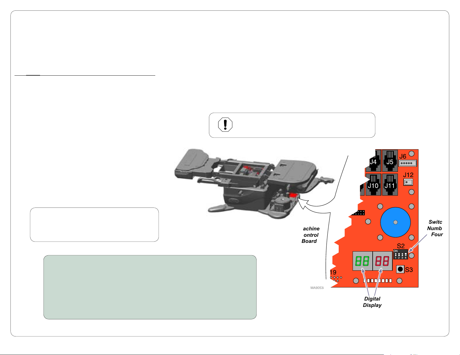
To calibrate...
A) Unplug chair power cord.
B) When the digital display darkens, move S2 switch number four to ON (up).
C) Plug in chair power cord.
D) When the digital display darkens, press and release S3 switch.
E) When calibration is complete, unplug chair power cord.
TP200 Rev. A
© 2014 Midmark Corp. | 60 Vista Drive Versailles, OH 45380 USA | 1-800-643-6275 | 1-937-526-3662 |
F) Move S2 switch number four to OFF (down).
G) When the digital display darkens, plug in chair power cord.
English-2
Machine
Control
Board
MA9053i
Switch
Number
Four
Digital
Display
Page 3

midmark.com
To install seat / back upholstery...
A) Position back section of chair flat.
B) Position front of seat section against seat mounting board.
C) Press seat section down firmly.
D) Position top of back section against the top of the back
mounting board.
E) Check for a consistent gap between seat and back sections.
F) Press back section down firmly.
TP200 Rev. A
© 2014 Midmark Corp. | 60 Vista Drive Versailles, OH 45380 USA | 1-800-643-6275 | 1-937-526-3662 |
MA9120i
English-3
 Loading...