

Midland Syn-Tech 70-342XL, 442XL, Syn-Tech 70-442XL Service Manual
VHF
(WIDE
BAND)
SERVICE
MANUAL
LAND MOBILE RADIO
1690
North
Kansas
Topping Avenue
City,
Missouri
bUVUUU
64120
MANUAL
09-342/442 XL
SM-8/86-1.5M
NO.
70-342442
PREFACE
70-342https://manualmachine.com/442~~
This service manual
the 70-342XL and 70-442XL transceivers. In the first section of this
manual, after transceiver description and specifications, instructions
for transceiver preparation
stallation, and summaries of available support equipment.
The second section of this service manual, entitled SERVICING,
dedicated to transceiver repair. Troubleshooting flow charts for
locating likely problem
General information follows, such
replacement instructions and realignment procedures.
Transceiver circuitry
herein respectively. Each PC board
diagrams;
Each schematic page has
be vi.ewed with
Because the PC boards have components and plating on both sides,
layout diagrams show superimposed images of plating patterns and
respective other-side-component maps. Any double-image layout of the
three PC boards can be viewed with their respective schematic without
turning pages.
all
of which can be viewed with their respective schematics.
it.
is
intended to facilitate set-up and service of
are
found-- programming, calibration, ir-
areas
is
contained on three PC boards and categorized
a
list
are
in the beginning of t-his section.
as
chip component identification and
is
detailed in text, charts, and
of other applicable diagrams that can
is
,
Information in this book
of the variety of readers' requirements, details of option add-ons
are
OPTIONS,
each add-on kit.
As
buted on the following forms:
Many useful facts and tips
intends to service several of the transceivers described herein,
spending
not included.
is
provided for allocating technical literature acquired with
necessary, service manual supplements
Manual Addition (MA)
Change Notice (CN)
Manual Correction (MC)
Technical Bulletin (TB)..For solutions to field problems and tips
time
to read applicable text
is
A
divider
.....
......
focused on the basic transceiver. Because
at
the end of this book, entitled
will
For supplemental information useful in
product alignment, service, or improvement. Printed on BLUE paper.
For circuitry change details made during
production by model and
Printed on YELLOW paper.
...
For correcting literature errors not
related to production changes. Printed
on GREEN paper.
for performance improvement. Print.ed on
PINK paper.
are
provided in the text. If the reader
will
be published and distri-
save
time
serial
in the end.
number.
TABLE
OF
Preface
Table of Contents
Description 3
Specifications:
ElPROM Programming:
Transceiver Calibration:
Installation:
Automotive Receiver Interference 31
Optional Accessories
Service Equipment 37
Service Tools
Optional Feature Add-on Kits 39
CONTENTS
.................................................
.......................................
70-342https://manualmachine.com/442~~
PAGE
ii
1
.............................................
General
Transmit
Receive
Scan and CTCSS
Programmable Parameters
H1
Version Programmer Software 10
ElPROM Module Removal
Programming
Set-up
Error Codes
Procedure 20
Instructions 22
Under-Dash Configuration 24
Trunk-Mount Configuration
Under-Dash Power/Accessory Plug 26
Trunk-Mount Power and Accessory Plugs 28
.............................................
............................................
.............................................
......................................
.............................
......................
...............................
.........................................
..............................................
.........................................
...........................................
........................................
............................
...........................
.....................
...............
........................
....................................
.......................................
...........................................
4
5
6
7
9
10
11
18
19
25
35
38
............................
SERVICING
Troubleshooting Charts:
General 45
CPU/Phase-Lock-Loop
Transmitter
Modulator
Receiver
Component Replacement:
Chip Component Identification
Replacing Components with Leads
Chip Capacitor and Resistor Replacement
Complete Alignment:
Set Up 53
Error Codes
Realignment
Factory Presets
.............................................
.................................
.........................................
...........................................
............................................
.......................
.....................
.............
..............................................
.........................................
.........................................
.....................................
continued
46
47
47
48
49
50
51
55
55
60
......
SERVICING continued:
Circuit Analysisf
Transmitter Board
Microprocessor Pinouts Chart
RF Power Amplifier Board
Receiver Board
Simplified Squelch Circuit Schematic
Metering
Block Diagram 77
Under-Dash Circuitry:
Under-Dash Interconnect Diagram
Front Panel Schematic Diagram
Front Panel PCB Layouts
70-342XL/442X~ Receiver PCB Layouts
DC Voltages
70-342XL Receiver Board Schematic Diagram
Trunk-Mount Circuitry:
Trunk-Mount Interconnect Diagram
Control Head
Control-Cable Interface Board
DC Voltages - Receiver Board
70-442XL Receiver Board Schematic Diagram
Transmitter Board:
DC Voltages - Transmitter Board
Microprocessor Pinouts (Duplicate Chart) 89
RF Power Amplifier PCB Layout 90
E/PROM Module Layout 90
Transmitter PCB Layouts
Transmitter
Under-Dash Exploded Mechanical
70-2301 Microphone
70-2195 Hang Up Box
Trunk-Mount Exploded Mechanical
Parts List 97
Parts Ordering 109
................................................
...........................................
..............................................
..........................................
...................................
........................
............................
......................................
....................
.....................
.......................
.............................
.................
-
Receiver Board
........................
...........
....................
........................................
.......................
........................
...........
.....................
............
.......................
................................
.............................
Board Schematic Diagram
View
Detail
Detail
...............................
..............................
View
.................
.....................
....................
61
63
69
71
75
76
78
80
81
82
83
83
84
85
86
87
87
88
91
93
94
95
95
96
OPTIONS
...................
GENERAL DESCRIPTION
The MIDLAND SYN-TECH 70-342XL and 70-442XL VHF wide-band Land-Mobile
transceivers are mobile two-way radios designed to operate on FM
channels between 136 to 174 MHz. There are two varieties of the SYNTECH 70-342XL and 70-442XL transceivers, each designed to operate on
different channel frequency range: the A-band radios (70-342AXL
442AXL) on the 136-163 MHz range; the B-band radios (70-342BXL
442BXL) on the 148-174 MHz range. SYN-TECH transceivers have the
capacity to operate on up to eighty operator selectable channels, each
of which can be programmed in the service shop.
is
The SYN-TECH 70-342XL transceiver
It
ing.
panel for easy access to the operator. The SYN-TECH 70-442XL transceiver
location.
pin
receptacle
long Control Cable that interconnects the 70-442XL remote unit with
its
Control Head. The Control Head contains all the operator controls
and
operator.
As
the SYN-TECH 70-342 and 70-442 transceivers, the XL models are
wide-band radios. Electronic tuning of critical stages
allow them to operate over a 24 MHz spread of channel frequencies.
has a control knobs, push buttons, and display all on a front
is
configured for mounting in a vehicle trunk or other remote
It
does not have front panel controls; instead
in
its
face-piece. The receptacle accepts the 4-meter
is
much smaller in size for mounting where accessible by the
configured for under-dash mount-
70-342https://manualmachine.com/442~~
&
&
it
has a 34-
is
used to
a
70713-
It
5
A
is
is
The XL models are revised 70-342 and 70-442 transceivers that used
KHz for their main VCO comparator frequency. The 70-342XL and 70442XL models use 2.5 KHz, thus allowing channel frequency increments
of 2.5 KHz for half-channels.
as
Many optional features, such
Complete add-on kits for field installation are readily available.
listing
Operating parameters such
and a variety of feature timing and codes
in an alterable memory module for easy customizing. The plug-in
memory module
E/PROM Programmer.
The 70-342XL and 70-442XL transceivers contain three major printed
circuit boards. The Transmitter Board contains transmitter, synthesizer, and microprocessor control circuitry.
components facing up, on the top side of the chassis center divider.
The Receiver Board also lays horizontally, but on the underside of the
chassis divider with components facing down. The third PC board
the RF Power Amplifier Board located inside the rear heat sink.
accessible by removal of the heat sink top cover.
with
brief kit descriptions can be found in later sections.
as
channel frequencies, CTCSS frequencies,
is
reprogrammable in the service shop using the MIDLAND
CTCSS, can be added at the factory.
are
electronically contained
It
lays horizontally, with
SPECIFICATIONS
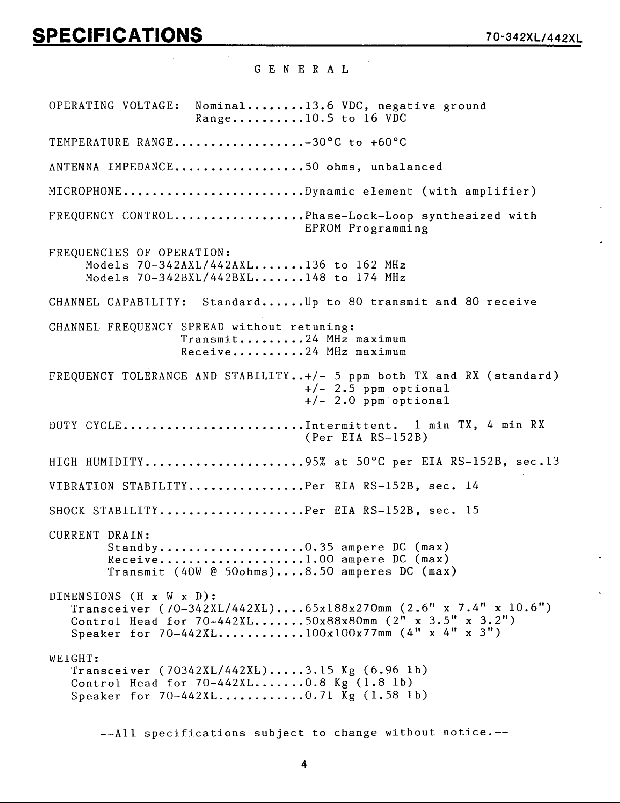
OPERATING VOLTAGE: Nominal....
Range 10.5 to 16 VDC
..........
GENERAL
....
13.6 VDC, negative ground
70-342https://manualmachine.com/442~~
TEMPERATURE RANGE
ANTENNA IMPEDANCE
MICROPHONE
FREQUENCY CONTROL
FREQUENCIES OF OPERATION:
Models 70-342AXL1442AXL 136 to 162 MHz
Models 70-342BXLl442BXL 148 to 174 MHz
CHANNEL CAPABILITY: Standard
CHANNEL FREQUENCY SPREAD without retuning:
FREQUENCY TOLERANCE
DUTY CYCLE
.........................
.........................
..................-
..................
..................
.......
.......
......
Transmit....
Receive.
AND
STABILITY..+/- 5 ppm both TX and
.....
.........
30°C to +60°C
50 ohms, unbalanced
Dynamic element (with amplifier)
Phase-Lock-Loop synthesized with
EPROM Programming
Up to 80 transmit and 80 receive
24 MHz
24 MHz
2.5 ppm optional
+/-
2.0 ppm'optional
+/-
Intermittent. 1 min TX, 4 min
(Per EIA RS-152B)
maximum
maximum
RX
(standard)
RX
HIGH
VIBRATION STABILITY
SHOCK STABILITY...
CURRENT
DIMENSIONS (H
WEIGHT:
HUMIDITY. 95%
DRAIN:
Standby
Receive..
Transmit (40W
Transceiver (70-342XLl442XL) 65xl88x270mm (2.6" x 7.4" x 10.6")
Control Head for 70-442XL 5Ox88x80mm (2" x 3.5" x 3.2")
Speaker for 70-442XL 100x100x77mm (4" x 4" x 3")
Transceiver (70342XL1442XL)
Control
Speaker
--All
.....................
................
.................
....................
..................
@
x
W
x D):
50ohms)
....
at
50°C per EIA RS-152B, sec.13
Per EIA RS-152B,
Per EIA RS-152B,
0.35 ampere DC (max)
1.00 ampere DC (max)
8.50 amperes DC (max)
sec.
sec.
14
15
....
.......
............
.....
Head for 70-442XL 0.8 Kg (1.8 lb)
for 70-442XL
specifications subject to change without notice.--
............
.......
3.15
0.71 Kg (1.58 lb)
Kg (6.96 lb)
SPECIFICATIONS
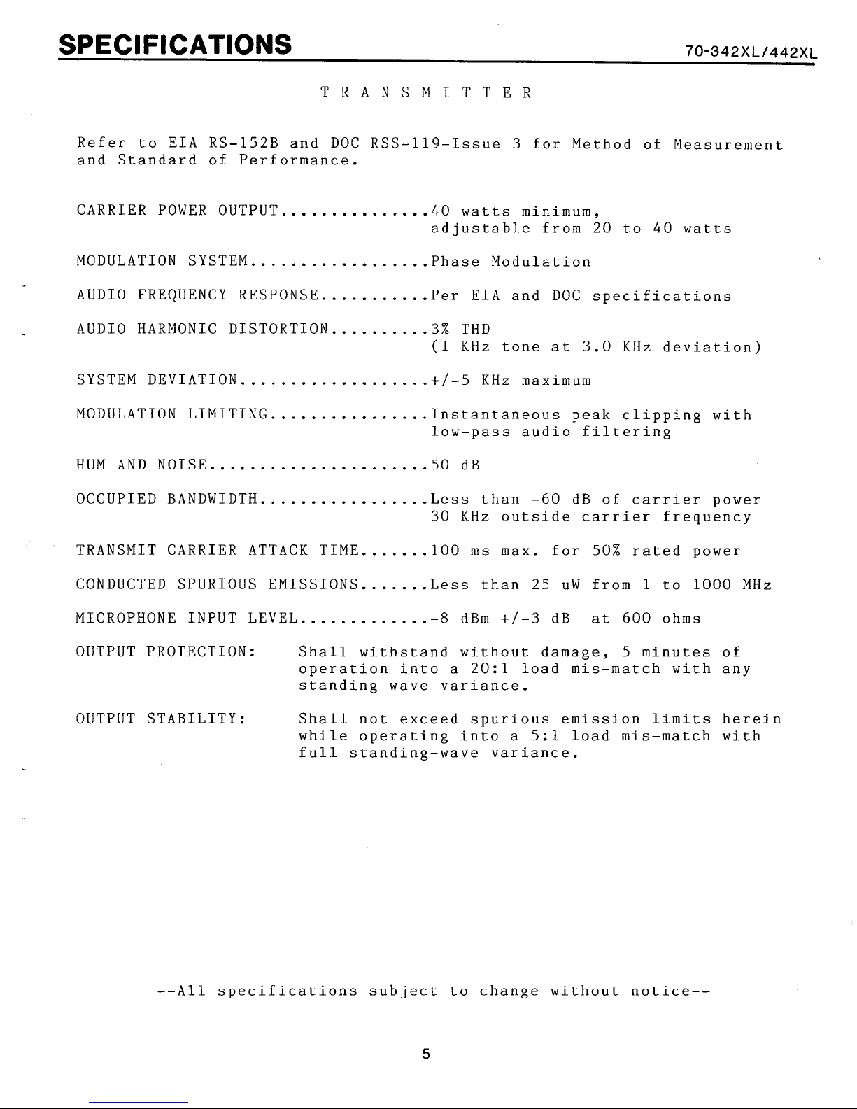
TRANSMITTER
Refer to EIA RS-152B and DOC RSS-119-Issue 3 for Method of Measurement
and Standard of Performance.
70-342https://manualmachine.com/442~~
CARRIER POWER OUTPUT
MODULATION SYSTEM
AUDIO FREQUENCY RESPONSE Per EIA and DOC specifications
AUDIO HARMONIC DISTORTION 3% THD
SYSTEM DEVIATION
MODULATION LIMITING
HUM AND NOISE
OCCUPIED BANDWIDTH...........
TRANSMIT CARRIER ATTACK TIME
CONDUCTED SPURIOUS EMISSIONS.
......................
...............
..................
...........
..........
...................+/-
................
......
.......
......
40
watts minimum,
adjustable from 20 to 40 watts
Phase Modulation
(1 KHz tone at 3.0 KHz deviation)
5
KHz maximum
Instantaneous peak clipping with
low-pass audio filtering
50 dB
Less than -60 dB of carrier power
30 KHz outside carrier frequency
100 ms max. for
Less than
25
50%
rated power
uW from 1 to
1000
MHz
MICROPHONE INPUT LEVEL.
OUTPUT PROTECTION: Shall withstand withcut damage,
OUTPUT STABILITY: Shall not exceed spurious emission limits herein
--All specifications subject to change without notice--
............-
operation into a 20:l load mis-match with any
standing wave variance.
while operating into a 5:l load mis-match with
full standing-wave variance.
8
dBm
+/-3
dB at
600
ohms
5
minutes of
SPECIFICATIONS
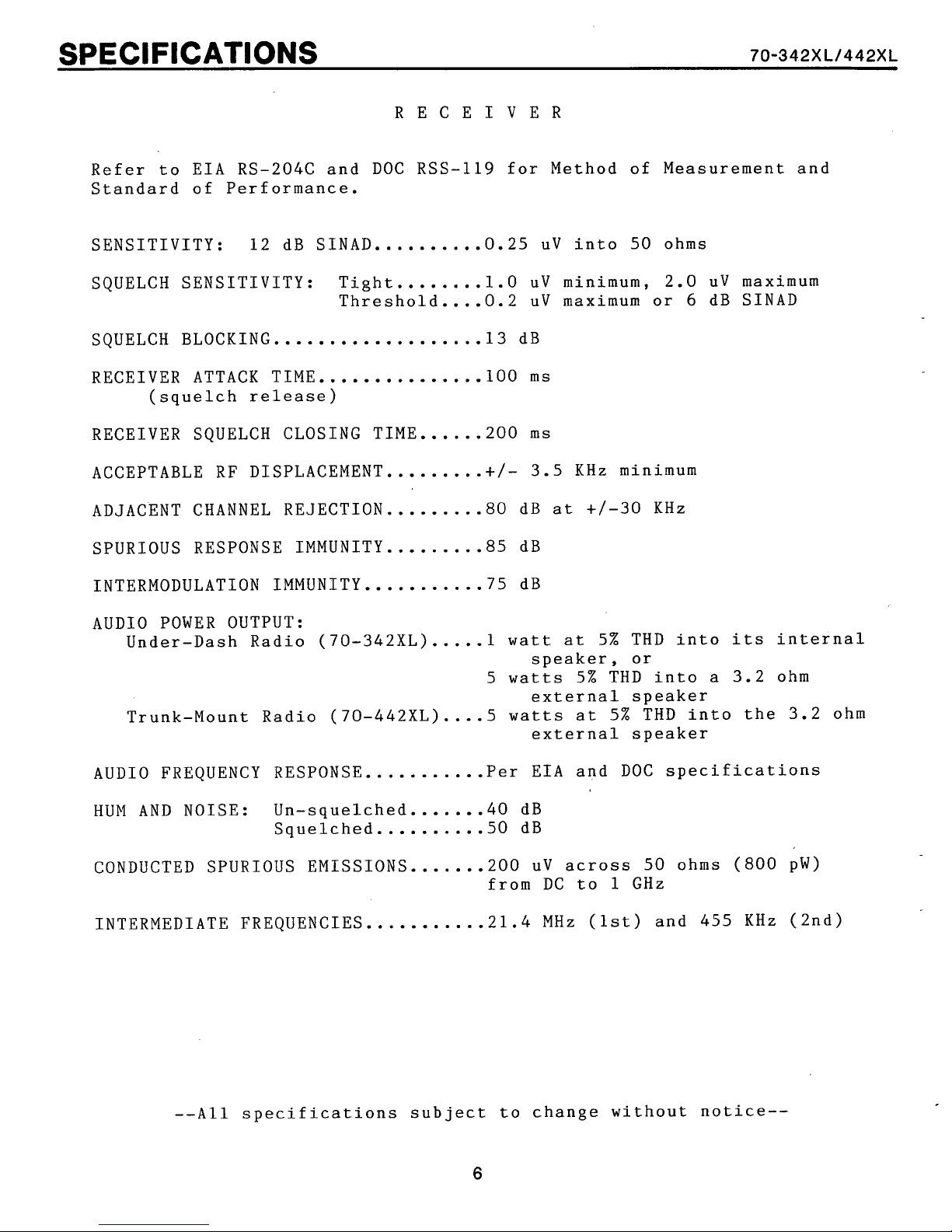
RECEIVER
Refer to EIA RS-204C and DOC RSS-119 for Method of Measurement and
Standard of Performance.
....
SENSITIVITY: 12 dB SINAD......
0.25 uV into 50 ohms
70-342https://manualmachine.com/442~~
SQUELCH SENSITIVITY: Tight
Threshold....0.2 uV maximum or
SQUELCH BLOCKING.. 13 dB
RECEIVER ATTACK TIME......... 100
(squelch release)
RECEIVER SQUELCH CLOSING TIME...
ACCEPTABLE RF DISPLACEMENT.........+/- 3.5 KHz minimum
ADJACENT CHANNEL REJECTION
SPURIOUS RESPONSE IMMUNITY.... 85 dB
INTERMODULATION IMMUNITY..... 75 dB
AUDIO POWER OUTPUT:
Under-Dash Radio (70-342XL)
Trunk-Mount Radio (70-442XL) 5 watts at 5% THD into the 3.2 ohm
.................
........
......
.........
.....
......
.....
1.0 uV minimum, 2.0 uV maximum
6
dB SINAD
ms
...
200
ms
80
dB at +/-30 KHz
1
watt at 5% THD into its internal
speaker, or
5 watts 5% THD into a 3.2 ohm
external speaker
....
external speaker
AUDIO FREQUENCY RESPONSE.....
HUM AND NOISE: Un-squelched
Squelched 50 dB
CONDUCTED SPURIOUS EMISSIONS.. 200 uV across 50 ohms
INTERMEDIATE FREQUENCIES 21.4 MHz (1st) and 455 KHz (2nd)
--All specifications subject to change without notice--
......
.......
..........
.....
...........
6
Per EIA and DOC specifications
40
dB
(800
from DC to 1 GHz
pW)
SCAN OPTION
Several of these parameters
are
programmable by E/PROM programming.
CHANNEL CAPACITY
OPERATOR CONTROL OF SCAN
PRIORITY CHANNEL SELECTION Any channel selectable by the oper-
INDICATION OF PRIORITY DETECTION
KEY-UP CHANNEL REVERT
EXTRANEOUSLY BUSY CHANNEL SKIP
PRIORITY CHANNEL SAMPLING RATE
SIGNAL DETECTION
...................
...........
.........
...
..............
.....
.....
...................
2 scan groups of 64 each
(duplicates allowed)
Three modes selectable by
push buttons
ator using the channel push buttons
Two-beep audible alert (elective)
Transceiver transmits on Priority
channel or
(depending on scan mode selected)
Channels can be skipped in scan by
DOWN
Every 4 or 8 channels, or every
or 2 seconds during scan hold
of carrier presence or vacancy; or
of correct CTCSS tone presence or
vacancy with
channel selection
last stopped channel
1
carrier
SCAN RESUME DELAY
SCAN SPEED (with standard timing):
Noise squelch busy detection 20 idle channels per second
CTCSS detection
CODE FREQUENCIES
MODULATION LIMITS 500 to 1000
DECODE SENSITIVITY
RECEIVER RESPONSE TIME
ENCODER RESPONSE TIME 50
TRANSMITTER TONE DISTORTION
AUDIO
DISTORTION WITH CTCSS TONE
..................
.....
..................
CTCSS OPTION
...................
..................
.................
.............
..............
........
...
0.3, 2.5, or 5 seconds or
lock
3
All
Less than 5 dB SINAD
200
5%
10%
&
hold until
channels per second if all busy
EIA standard from
Hz
ms
maximum
ms
maximum
maximum
reset
67
carrier
to 241.8Hz
deviation
--All
specifications subject. to change without notice--
7

E/PROM PROGRAMMING
The 70-342XL and 70-442XL transceivers contain an Erasable/Program-
mable Read Only Memory (E/PROM) module. The module holds specific
customer frequencies, feature selections, and other parameters that
determine radio operation.
Before final alignment and check, the module must be reprogrammed with
customer specifics. If any option add-on kits are to be installed,
appropriate parameters may also need to be programmed as instructed in
respective kit installation literature.
To change ElPROM electronic information, the plug-in module must first
be erased by exposing it to ultraviolet light using the MIDLAND 701100/1101 ElPROM Eraser. Then, reprogramming is necessary using the
MIDLAND 70-1000 ElPROM Programmer. Operation parameter information is
entered into the Programmer through its keypad, converted into binary
data useful to the transceiver, then written into the E/PROM.
The following are programmable operation parameters in the SYN-TECH
mobile transceivers. See the 70-1000 E/PROM Programmer Operator's
Manual (No. 70-999113) for details.
1.
All eighty transmit and eighty receive channel frequencies
2.
All standard CTCSS tones for each TX and RX channel (requires
installation of the CTCSS module within the transceiver)
3. Time-out-timer time (maximum continuous transmission
duration)
4.
Scan parameters as follows:
a. Two scan groups, each containing up to sixty-four
channels
A
b.
c. Either presence or absence of carrier or correct CTCSS
d. Channel sampling rate (time spent looking for carrier
e. CTCSS decode time (time allotted for decoding after
f. Scan hold time (delay of scan resume after channel
g. Post-transmit scan hold time (delay of scan resume
h. Retention of scan list channels deleted (skipped) by
5.
Busy channel lockout with or without alert tone to the
operator. Adding jumpers allows busy channel inhibit by
CTCSS tone status. See "BCLO JUMPERING".
6.
Transmit-to-receive changeover delay of up to 200ms for
special options.
7. Last selected channel recall on power-up may be disabled.
variety of priority/scan channel revert arrangements
utilizing the two channel lists.
tone to indicate a busy channel
presence on each channel)
carrier is detected)
clears)
after PTT release)
operator activation of the DOWN selector while in scan
mode. Normally, these selections are erased by release
of the SCAN and PRI push buttons and power-down. Programming limits erasure to power-down only.
70-342https://manualmachine.com/442~~
H1 VERSION UPGRADE
The E/PROM programmer, model 70-1000, must contain H1 or later version
software to program all features and parameters into the 2-273 E/PROM
modules that are used in the 70-342XL and 70-442XL transceivers. The
version level of software installed in the programmer is identified
for one second in the two far right digits displayed after power-up.
If your programmer contains software that,is older (lower letter) than
the H1 version, upgrade is required. To date of this printing, the
newer L3 version software is current and available (in its own E/PROM)
in Update Kit No. 70-1411. The 70-1000 Operator's Manual also has
been rewritten. The May, 1985 printing can be ordered as MIDLAND part
number 70-999113.
CDCSS OPTION
If the Continuous Digital Coded Squelch System option is installed in
the transceiver, the ElPROM Module is different. This Module, MIDLAND
number 70-2402, is larger in size to accommodate an additional receptacle for connection to the CDCSS board. When programming, the ElPROM
type selection entered into the Programmer is the same as for the
standard EIPROM.
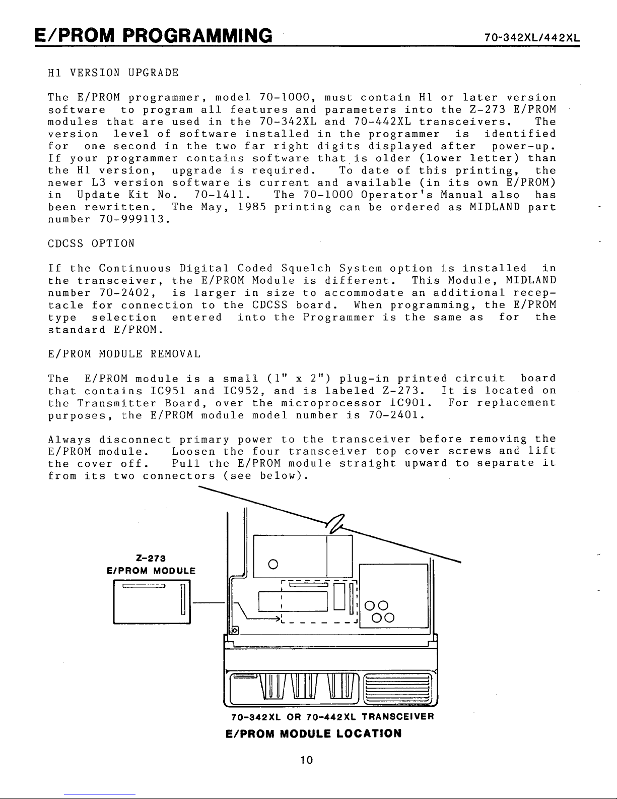
ElPROM MODULE REMOVAL
The E/PROM module is a small (1"
x
2") plug-in printed circuit board
that contains IC951 and IC952, and is labeled 2-273. It is located on
the Transmitter Board, over the microprocessor IC901. For replacement
purposes, the ElPROM module model number is 70-2401.
Always disconnect primary power to the transceiver before removing the
E/PROM module. Loosen the four transceiver top cover screws and lift
the cover off. Pull the E/PROM module straight upward to separate it
from its two connectors (see below).
70-342XL
OR
70-442XL
TRANSCEIVER
E/PROM MODULE LOCATION
E/PROM PROGRAMMING
PROGRAMMING
The following E/PROM programming procedure covers most programming for
transceiver operation. Certain infrequently modified parameters are
as
excluded (parameters listed
programming procedures can be found in the Programmer Operator's
Manual.
Heed this precaution:
Do not apply or remove AC-line power to the Programmer while an
E/PROM module
able, to plug the module onto the Programmer until all parameter
information
ready for the BLANK-WRITE-VERIFY operation (step 25).
is
plugged into
is
keystroke entered. Connect the module only when
4h, 6, and 7 on page nine). Complete
it.
It
is
not necessary, nor advis-
70-342https://manualmachine.com/442~~
1.
2. Turn the 70-1000 Programmer on. One of these self-test messages
3.
Erase the E/PROM module in the 70-1100/1101 Eraser. Assure the
E/PROM window
Refer to the Eraser instruction manuax for details.
must appear in the FREQUENCY display for one second: "PASSOL3",
"PASSlL3", "PASSOHll', or "PASSIHll'. The
the required software revision level
programmer. After two seconds, "TYP" should appear in the BAND
display. If an earlier version software
VERSION UPGRADE preceding.
Enter the heading (not necessary for transceiver operation, but
recommended for organization) by pressing [MANUAL], then [ENTER],
then the following:
a. The second part of the transceiver model number ('342A1,
for example). Then [ENTER].
b. Transceiver eight digit
Then [ENTER].
c.
First three digits of a ten digit customer number
(ex.: '123'). Then [ENTER].
d. The last seven digits of the customer number
(ex.: '9ABCDEF1). Then [ENTER].
e.
The month numerically (ex.: March = '3'). Then [/I.
f. The date ('1' through '31'). Then [/I.
g. The
h. Press [RESET] to close heading sequence.
is
last
clean, and
two digits of the year (ex.: '86'). Then [ENTER].
set
serial
exposure
H1
number (ex.: '12345678').
time
last
or L3
is
for 45 minutes.
two digits indicate
is
installed,
installed in the
see
H1
--E/PROM Type Selection--
4.
Press [l] to
should appear. (If the transceiver contains either Talk-Around
option 70-2815 or 70-2816,
by pressing [7] instead of [I]) Press [ENTER].
select
the standard 2-273 E/PROM Module. "2-273"
select
the Z-273TA E/PROM Module type
E/PROM PROGRAMMING
70-342https://manualmachine.com/442~~
5.
--Channel Frequency Programming--
The CHANNEL display indicates the numeric channel designator that
appear in the transceiver display. The STEP display indicates what
entry
If an invalid frequency
quency display
frequency.
6.
Select the VHF band and 2.5 KHz PLL reference code by pressing
[2], then [Dl. "15d" should appear in the BAND display (if the
transceiver has been modified with 70-2178 or 70-2179 High-Side
Injection
[ENTER]. The Programmer should now be ready for channel
frequency entry.
is
to be made for that channel--
"1"
"2"
"3"
"4"
CHANNEL
desired receive frequency for channel
point. Then press [ENTER].
Kits,
=
receive frequency
=
receive CTCSS tone frequency or receive CDCSS code
=
transmit frequency
=
transmit CTCSS tone frequency or transmit CDCSS code
will
"1"
use band code [El instead of [Dl). Press
is
entered in the following steps, the fre-
flash. Press [CLEAR], then reenter the correct
and STEP
"1"
should now be displayed. Key in the
1
including the decimal
will
7. CHANNEL
option
or CDCSS code can be entered as described below.
CTCSS Key in the desired CTCSS tone frequency to be decoded
including the decimal point (only standard EIA frequencies
are
Press [ENTER]. If
coded squelch option
CDCSS Key in the desired three-digit standard decode code
(only EIA standard codes
in the FREQUENCY display. If signal
after digits.
carrier squelch operation
option
The Programmer contains
frequencies and CDCSS codes, any of which each
this mode. Press
again to increment through them one
are
stacked on top of the CTCSS tone
scrolling past the highest CTCSS tone. Press [C] to decrement
through the
displayed, press [ENTER] to program.
"l",
is
valid). The digits
STEP "2", should be displayed. If a coded squelch
installed in the transceiver, the CTCSS tone frequency
will
carrier
is
not installed, enter zero.
A
"-"
will
is
installed, enter zero.
a
table of EIA standard CTCSS tone
[Dl
to
call
lists.
When the desired frequency or code
appear in the FREQUENCY display.
squelch operation
are
valid). The digits
is
inverted, key [A]
appear. Press [ENTER]. If
is
desired or no coded squelch
the CTCSS tone frequencies and
at
a
time.
list,
and should appear when
is
desired or no
will
are
accessible in
The CDCSS codes
is
appear
E/PROM PROGRAMMING
70-342https://manualmachine.com/442~~
8.
9. CHANNEL
10. Repeat steps 6 through
--Center Frequency Programming--
To afford wideband capability, the self-tuned 70-342XL and 70-442XL
transceivers switch the operating range of their VCO's when selected
channel frequency crosses
controlled by the microprocessor and must programmed into the E!PROM.
Center Frequency values entered into the E/PROM depend on the transceiver frequency band (A-band or B-band).
CHANNEL
transmit frequency for channel
Then press [ENTER]. If the transmitter
channel
is
equipped with a coded squelch option, key in the desired CTCSS
tone frequency or CDCSS code to be transmitted, or nothing for no
tone/code transmission. Then press [ENTER]. The tone/code table
can be used in this mode also.
channels. Channels may be skipped and left unprogrammed.
Channels can be scrolled and re-accessed using the up and down
arrows.
"l",
1,
"l",
STEP
enter zero.
STEP "4", should be displayed. If the transceiver
"3",
should be displayed. Key in the desired
1
including the decimal point.
is
to be disabled in
10
to program the remaining seventy-nine
a
range-center frequency. This switching
is
11.
12. STEP
13.
--Scan Channel Entry--
14. Channel and tone frequency entry
Scroll backward through the channel
arrow push button. Whenever the
channel
accessed and "CF" appears in the CHANNEL display. Stop on the CF
channel.
Frequency entry. Key in '148.12' if the transceiver
model (136-162 MHz range) or key in '160.92' if the transceiver
is
a
STEP
Frequency entry (STEP 2 and 4 do not apply, therefore do not
appear with the CF channel). Key in '147.20' if the transceiver
is
an A-band model (136-161 MHz range) or '160.00' if the
transceiver
[ENTER].
begin scan channel programming sequence. The display
bgank except for the SCAN indicator.
0
to channel 79, the Center Frequency 'channel'
"1"
will
B-band model (148-174 MHz range). Press [ENTER].
"3"
will
also appear, showing readiness for receive Center
appear, showing readiness for transmit Center
is
a B-band model (148-174 MHz range). Press
list
list
is
complete. Press [SCAN] to
with the appropriate
is
looped backwards from
is
will
is
an A-band
be
There are two
list
the transceiver during scan operation differently, depending on
selection of the PRI and SCAN push buttons and Function Mode
programming. Details of operation are found in both the
transceiver and the Programmer operator's manuals.
can be up t.o 64 channels long. The two
lists
of scan channels available--A and B. Each
lists
are used by
E/PROM
PROGRAMMING
70-342https://manualmachine.com/442~~
15. Press [A] to program the
display and the first
the BAND display.
16. Key in the channel number to be scanned first in the
press [ENTER]. While
in the CHANNEL display.
17.
18.
19. When the
After [ENTER]
display)
and press enter. If you make an error, press [CLEAR] and
enter. If the channel entered
frequency entry steps above, the CHANNEL display
indicate the error. Press [CLEAR] and enter
Continue entry of the A scan
several scan sequence spots to cause
To
scroll through the
each sequence designator assignment. The highest designator
63.
in the STEP display and the lowest B
designator (0) should appear in the BAND display. Enter B scan
list
highest
will
A
channels in the
list
is
pressed, the
increment to
list
entry
sequence designator
A
list.
list
it
sequence designator "0"
is
keyed, the channel number
1.
list.
A
list,
is
complete, press [B]. "b" should appear
same
manner as A list
"A"
will
A
list
Key in the second A scan channel
was
press the up and down arrows to
sequence designator (BAND
left blank in the channel
A
channel can be entered in
it
list
is
63.
appear in the STEP
will
will
a
valid channel.
to be sampled more often.
scan sequence
entry. Again, the
appear in
A
list,
will
flash to
appear
re-
then
see
is
2C. Press [RESET] to exit the scan programming mode. The Channel
frequency entry mode
"l",
The Busy Channel Lockout feature, Time-Out-Timer feature, and scan
feature parameters
these eight parameters need programming for most applications, therefore attention
program the others (timing adjustments, etc.) can be found in the
Programmer Operator's Manual.
21. BCLO Press [FUNC.] then [ENTER]. "FnC"
display and
programming the Busy Channel Lockout (BCLO) feature,
active. Key in one of the following values, then press [ENTER].
If no entry
value of
for jumper considerations.
and the appropriate frequency.
are
is
given to only these four hereinafter. Procedures to
"1"
in the STEP display. Function Code
is
made, the transceiver
3
--no BCLO. Also
will
programmed in the Function Mode. Only four of
resume displaying CHANNEL
will
will
see
"BCLO JUMPERING'' in this section
operate per the default
appear in the BAND
"OM,
1,
for
is
now
STEP
E/PROM
21. continued...
BCLO parameters:
Throughout Function Mode programming, the up and down arrows will
sequentially select the Function Codes.
22. Time-Out-Timer "FnC" and "2" will be displayed. Key in the
parameter value
below, then press [ENTER]. When the transmitter is continuously
keyed for the programmed duration, the timer disables the
transmitter and applies an audible alert tone to the speaker.
The
default value of
inoperative.
PROGRAMMING
O= BCLO without alert. No audible indicating tone will be
heard.
2= BCLO with alert. When the PTT button is pressed while ths
transceiver is inhibited, a tone will be applied to the
speaker.
3= BCLO disabled. No transmit inhibiting per receive status.
to set the Time-Out-Timer duration as listed
timer is reset upon PTT release. If no entry is made, the
0
will be automatic, leaving the Time-Out-Timer
70-342https://manualmachine.com/442~~
O= Disable the Time-Out-Timer
1= 30 seconds
2=
60
seconds
90
3=
23. Press the up arrow four times to skip to Function Code 7.
Function Codes 3 through
their default values.
scan timing, refer to the Programmer Operator's Manual for
procedure.
24. Priority Monitoring '!FnC1' and "7" should be displayed.
Entering a value in this mode either disables priority channel
(see
function is not programmed, the default is one Priority channel
sampling every eight channels scanned, and one Priority sampling
every second when scan is stopped on an active non-priority
channel.
Key in a value listed below, then [ENTER], to program the desired
sampling rates.
erato tor's
O=
1=
2= Sample the Priority channel once every four non-priority
3=
4=
seconds 7= 210 seconds
6
will automatically be programmed with
If
a special application requires altering
manual) sampling or changes its rate.
Sample the Priority channel once every four non-priority
channels scanned, and sample it every second when scan is
stopped.
Sample the Priority channel once every eight non-priority
channels scanned, and sample it every second when scan is
stopped.
channels scanned, and sample it every two seconds when
scan is stopped.
Sample the Priority channel once every eight non-priority
channels scanned, and sample it every two seconds when
scan is stopped.
Disable Priority monitoring
4=
120 seconds
5=
150 seconds
6=
180 seconds
If
this
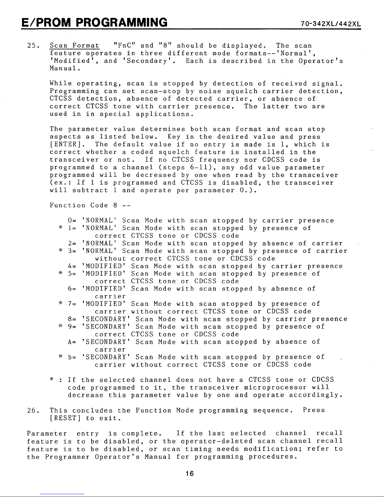
25.
Scan Format "FnC1' and
feature operates in three different mode formats--'Normal1,
'Modified', and 'Secondary'. Each
Manual.
"8"
should be displayed. The scan
is
described in the Operator's
While operating, scan
Programming can
CTCSS detection, absence of detected
correct CTCSS tone with
used in in special applications.
The parameter value determines both scan format and scan stop
aspects
[ENTER]. The default value if no entry
correct whether a coded squelch feature
transceiver or not. If no CTCSS frequency nor CDCSS code
programmed to a channel (steps 6-11), any odd value parameter
programmed
(ex.: If
will
Function Code
*
*
*
*.7=
$5
*
as
listed below. Key in the desired value and press
will
1
is
subtract 1 and operate per parameter 0.).
O=
'NORMAL' Scan Mode with scan stopped by carrier presence
1=
'NORMAL' Scan Mode with scan stopped by presence of
correct CTCSS tone or CDCSS code
2=
'NORMAL' Scan Mode with scan stopped by absence of
3=
'NORMAL' Scan Mode with scan stopped by presence of
without correct CTCSS tone or CDCSS code
4=
'MODIFIED' Scan Mode with scan stopped by
5=
'MODIFIED' Scan Mode with scan stopped by presence of
correct CTCSS tone or CDCSS code
6= 'MODIFIED' Scan Mode with scan stopped by absence of
carrier
'MODIFIED' Scan Mode with scan stopped by presence of
carrier
8=
'SECONDARY' Scan Mode with scan stopped by
9=
'SECONDARY' Scan Mode with scan stopped by presence of
correct CTCSS tone or CDCSS code
A=
'SECONDARY' Scan Mode with scan stopped by absence of
ca'rrier
b= 'SECONDARY' Scan Mode with scan stopped by presence of
carrier without correct CTCSS tone or CDCSS code
set
be decreased by one when read by the transceiver
programmed and CTCSS
8
--
is
stopped by detection of received signal.
scan-stop by noise squelch carrier detection,
carrier
carrier,
presence. The
is
is
is
disabled, the transceiver
or absence of
latter
made
installed in the
is
1,
two
are
which
is
carrier
is
carrier
carrier
without correct CTCSS tone or CDCSS code
carrier
presence
presence
,.
*
:
If the selected channel does not have a CTCSS tone or CDCSS
code programmed to
decrease this parameter value by one and operate accordingly.
26.
Parameter entry
feature
feature
the Programmer Operator's Manual for programming procedures.
This concludes the Function Mode programming sequence. Press
[RESET] to exit.
is
complete. If the last selected channel recall
is
to be disabled, or the operator-deleted scan channel recall
is
to be disabled, or scan timing needs modification; refer to
it,
the transceiver microprocessor
will
E/PROM PROGRAMMING
70-342https://manualmachine.com/442~~
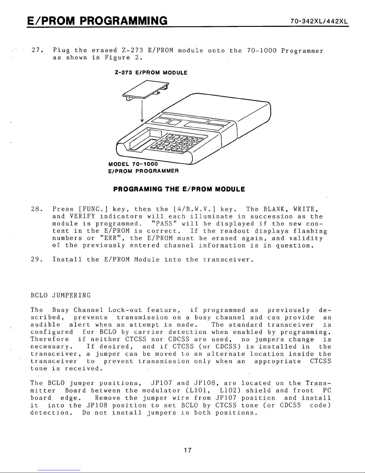
27. Plug the erased 2-273 ElPROM module onto the 70-1000 Programmer
as shown in Figure
2.
2-273
MODE
EIPROM PROGRAMMER
PROGRAMING
EIPROM MODULE
THE
E/PROM MODULE
28. Press [FUNC.] key, then the [4/B.W.V.] key. The BLANK, WRITE,
and VERIFY indicators
module
is
programmed. "PASS"
tent in the E/PROM
will
is
correct. If the readout displays flashing
each illuminate in succession as the
will
be displayed if the new con-
numbers or "ERR", the E/PROM must be erased again, and validity
of the previously entered channel information
is
in question.
29.
Install the E/PROM Module into the transceiver.
BCLO JUMPERING
The Busy Channel Lock-out feature, if programmed as previously described, prevents transmission on
audible
alert
when an attempt
is
a
busy channel and can provide an
made. The standard transceiver
is
configured for BCLO by carrier detection when enabled by programming.
Therefore if neither CTCSS nor CDCSS are used, no jumpers change
necessary. If desired, and if CTCSS (or CDCSS)
transceiver,
a
jumper can be moved to an alternate location inside the
is
installed in the
is
transceiver to prevent transmission only when an appropriate CTCSS
tone
is
received.
The BCLO jumper positions, JP107 and JP108, are located on the Transmitter Board between the modulator (L101, L102) shield and front PC
board edge. Remove the jumper
it
into the JP108 position to
set
wire
from JP107 position and install
BCLO by CTCSS tone (or CDCSS code)
detection. Do not install jumpers in both positions.
TRANSCEIVER CALIBRATION
70-342https://manualmachine.com/442~~
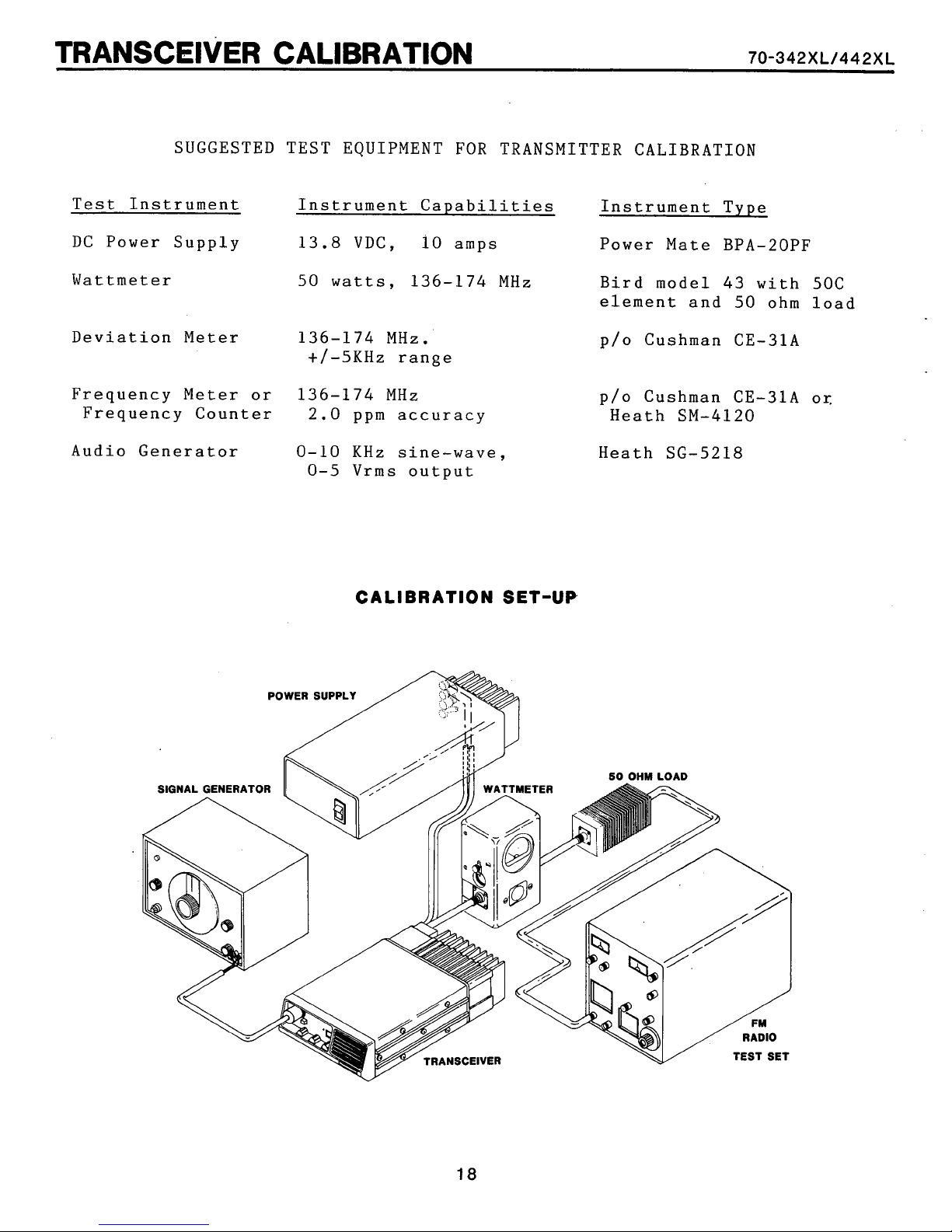
SUGGESTED TEST EQUIPMENT FOR TRANSMITTER CALIBRATION
Test Instrument Instrument Capabilities Instrument Type
DC Power Supply 13.8 VDC, 10 amps Power Mate BPA-20PF
Wattmeter
50 watts, 136-174 MHz Bird model 43 with 50C
element and 50 ohm load
Deviation Meter 136-174 MHz.
p/o Cushman CE-31A
+/-5KHz range
Frequency Meter or 136-174 MHz p/o Cushman CE-31A or.
Frequency Counter 2.0 ppm accuracy Heath SM-4120
Audio Generator 0-10 KHz sine-wave, Heath SG-5218
0-5 Vrms output
POWER
CALIBRATION
SUPPLY
SET-UP
TRANSCEIVER CALIBRATION
The 70-342XL and 70-442XL wideband transceivers are capable of opera-
ting across
realignment
frequencies. Only transmit carrier calibration such as frequency,
modulation, and output power may need adjustment. The transceivers
are shipped from the factory programmed with test frequencies that
must be changed to customer frequencies before installation.
REALIGNMENT
sceiver tuning has been replaced. Realignment requires transceiver
operation on special frequencies, therefore they must be programmed
into the transceiver E/PROM specifically for alignment. The complete
Alignment procedure can be found in the SERVICING SECTION of this
manual.
a
24
MHz channel frequency spread. Therefore, receiver
is
not needed, even when reprogrammed with new customer
MAY
BE NECESSARY ONLY AFTER a component that affects tran-
-
70-342https://manualmachine.com/442~~
Error code 90, 91, 92, 93, or 94 appearing in the channel display with
-
continuous triple-beeps indicates the E/PROM module
improperly inserted, or incorrectly programmed. Check the E/PROM
module or refer to the E/PROM Programming section in this service
manual.
Error code 95 appearing in the channel display with
indicates the synthesizer phase-lock-loop cannot achieve lock.
defect exists and
it
must be corrected.
is
missing,
a
triple-beep
A
TRANSCEIVER CALIBRATION
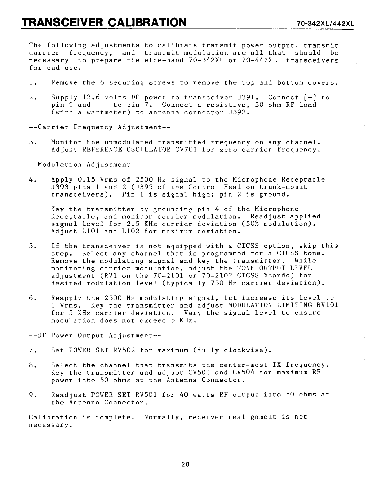
The following adjustments to calibrate transmit power output, transmit
carrier frequency, and transmit modulation are all that should be
necessary to prepare the wide-band 70-342XL or 70-442XL transceivers
for end use.
8
1. Remove the
securing screws to remove the top and bottom covers.
70-342https://manualmachine.com/442~~
2.
--Carrier Frequency Adjustment--
3. Monitor the unmodulated transmitted frequency on any channel.
4.
5.
Supply 13.6 volts DC power to transceiver 5391. Connect
9
and
[-I
pin
(with a wattmeter) to antenna connector 5392.
Adjust REFERENCE OSCILLATOR CV701 for zero carrier frequency.
Apply 0.15 Vrms of 2500 Hz signal to the Microphone Receptacle
5393 pins 1 and 2 (5395 of the Control Head on trunk-mount
transceivers). Pin 1 is signal high; pin 2 is ground.
Key the transmitter by grounding pin
Receptacle, and monitor carrier modulation. Readjust applied
signal level for 2.5 KHz carrier deviation (50% modulation).
Adjust LlOl and L102 for maximum deviation.
If the transceiver is not equipped with a CTCSS option, skip this
step. Select any channel that is programmed.for a CTCSS tone.
Remove the modulating signal and key the transmitter. While
monitoring carrier modulation, adjust the TONE OUTPUT LEVEL
adjustment (RV1 on the 70-2101 or 70-2102 CTCSS boards) for
desired modulation level (typically 750 Hz carrier deviation).
to pin 7. Connect a resistive, 50 ohm RE load
4
of the Microphone
[+]
to
6.
--RE Power Output Adjustment--
7.
8.
9.
Calibration is complete. Normally, receiver realignment is not
necessary.
Reapply the 2500
1 Vrms. Key the transmitter and adjust MODULATION LIMITING RVlOl
5
for
modulation does not exceed
Set POWER SET RV502 for maximum (fully clockwise).
Select the channel that transmits the center-most TX frequency.
Key the transmitter and adjust CV501 and CV504 for maximum RE
power into 50 ohms at the Antenna Connector.
Readjust POWER SET RV501 for
the Antenna Connector.
KHz carrier deviation. Vary the signal level to ensure
Hz
modulating signal, but increase its level to
KHz.
5
40
watts RF output into 50 ohms at
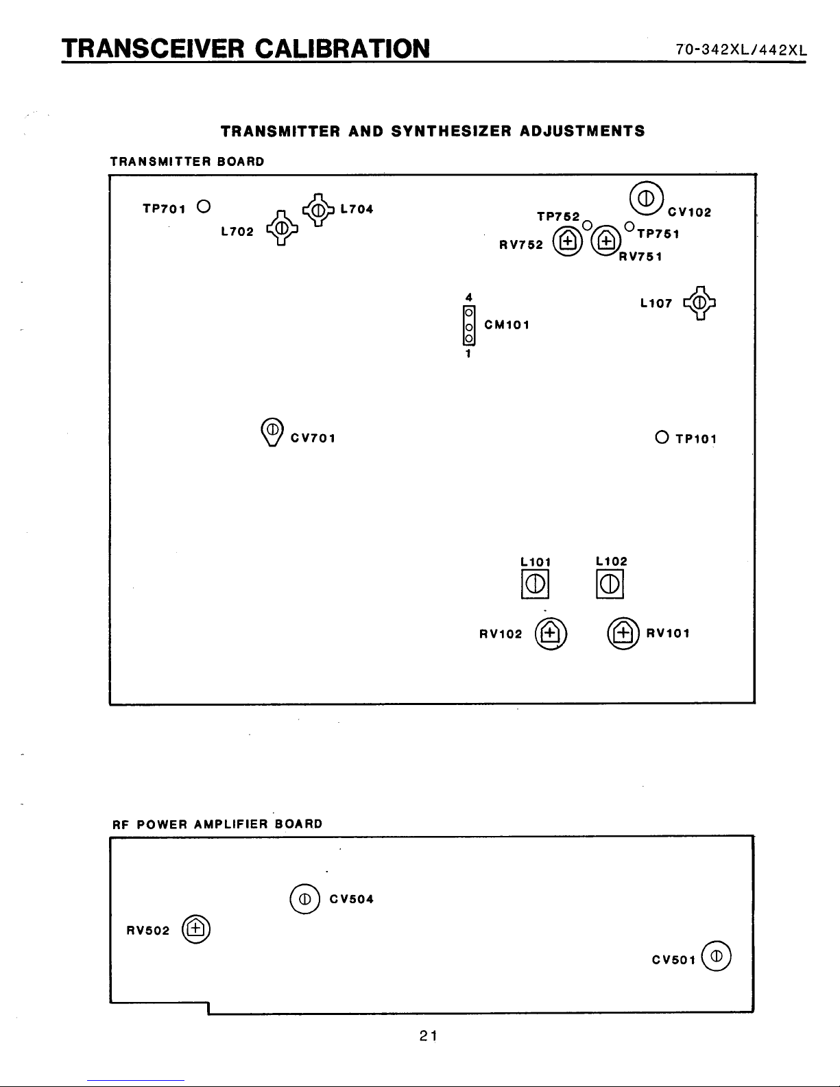
TRANSCEIVER CALIBRATION
TRANSMITTER AND SYNTHESIZER ADJUSTMENTS
TRANSMITTER BOARD
70-342https://manualmachine.com/442~~
RF POWER AMPLIFIER BOARD
UNDER-DASH MOUNTING (Model 70-342XL only)
The 70-342XL transceiver
is
designed for use in automobiles, trucks,
or other vehicles with 12 volt electrical systems. Where in the
vehicle the transceiver
provided
its
front panel controls
mounted does not affect
are
accessible to the operator.
its
performance,
is
Typical mounting locations are under the dashboard or next to the
driver's
The transceiver
seat.
is
housed in
a
slim,
small
package to best conform to
mounting locations. The mounting bracket slides into the transceiver
a
siderails and provides
3.25 x 7.75 inch flat surface across the
transceiver top with holes for bolting to a flat surface in the vehi-
cle.
the four
5/32" holes must be drilled in the mounting surface to accept
3/8"
screws and washers provided.
TRUNK MOUNTING (Model 70-442XL only)
is
The 70-442XL trunk mount transceiver
such
a
ceiver
design,
as
a
vehicle trunk or under a seat. The operator controls
compact control head for operator access. The bulk of the trans-
is
within the separate remotely mounted unit. Because of this
its
does not have an internal speaker. Instead,
designed for remote mounting
are
in
a
separate
3.2-ohm external speaker (included with the 70-442XL package) nust be
installed and connected to the Control Head.
The cable that interconnects the control head to the trunk unit
is
four meters long and flat for laying under carpeting. The cable must
not lay near hot areas (above the catalytic converter, for example)
nor against sharp edges.
A
trunk unit mounting tray
is
flat tray
the trunk unit
7.5 inches square and must be bolted to the surface where
will
mount. 5/32" holes must be drilled in the mount-
ing surface to accept the four
13
x 8 x 3 inch trunk unit then clips onto the tray.
A
Control Head mounting bracket.
Its
surface
is
314 inch wide and 4 inches long with two screw holes
is
provided with each transceiver. The
3/8"
screws and washers provided. The
is
provided with each transceiver.
2
inches apart. 5/32" holes must be drilled in the mounting surface of
the vehicle to accept the the
318"
Control Head and bracket assembly
wide, and
3
112 inches deep.
At
screws and washers provided. The
is
2 112 inches high, 4 114 inches
least
314 inch of additional depth
is
needed for the connectors that attach to the rear of the Control Head.
REMOTE SPEAKER (required and included with the 70-442XL)
As
part of the standard trunk-mount transceiver configuration (model
70-442XL), the model 70-2353 5-watt speaker connects to the Control
Head Accessory Plug.
It
also can be used optionally with the 70-342XL
under-dash transceiver to substitute the transceiver internal speaker.
Its
5
112 ft. cable
is
terminated with appropriate Molex pins for
1
INSTALLATION
insertion into the trunk-mount Accessory Plug on the Control Head or
the under-dash Power/Accessory Plug. The speaker housing and mounting
bracket assembly
is
surface
4 1/4 x 1 114 inches, with four 3/32"
POWER REQUIREMENTS
Both the 70-342XL and 70-442XL transcqivers are designed to operate
a
from
12 volt DC, negative ground, automotive
Current drain of
of the vehicle
other
electrical
CAUTION: CHECK THE VOLTAGE SOURCE BEFORE CONNECTING THE POWER CABLE.
TOO MUCH VOLTAGE (ABOVE
70-342https://manualmachine.com/442~~
is
5x5 inches square by 3 inches deep. The mounting
at
least 10 amperes should be expected. Inspection
is
recommended prior to installation.
screw
slots.
electrical
A
low battery or
system.
system defects may degrade transceiver performance.
16
VOLTS) CAN SEVERELY DAMAGE THE TRANSCEIVER.
Included with the trunk-mount transceiver
The under-dash transceiver
is
shipped with a 2
is
a
6
meter
meter
DC power cable.
Power/Accessory
cable. Each cable includes fused power leads for connection to vehi-
cle
to the negative
GROUND VEHICLE. If the transceiver
electrical
system. Because the transceiver chassis
(-)
lead,
DO
NOT INSTALL THE TRANSCEIVER
is
used as a base station, the
is
connected
IN
A
POSITIVE
external AC-line-to-DC power supply must be adequately regulated and
have sufficient current capacity.
ANTENNA
The most important communications system component that can affect
overall performance
to provide 50 ohm terminating impedance
frequencies
follow
its
is
manufacturer's instructions.
is
the antenna.
A
good quality antenna designed
at
appropriate transceiver
recommended. When adjusting the antenna, be sure to
A
better quality SWR
meter
should be used to accurately measure minimum reflected energy.
MICROPHONE HANGER
The hand microphone included with the transceiver has
backside to
three
screws
screws and three 314"
mate
with
its
hang-up clip. The clip must be mounted with
in a location convenient to the operator. Three 1/2"
screws,
each requiring a 5/64" hole,
button on
are
its
also
a
provided.
An optional microphone hanger (model 70-2195)
with the CTCSS option. This hang-up box may be installed in place of
the microphone clip on both
screws
provided. Wiring instructions fol3.o~ in the Power/Accessory
Plug instructions.
metallic
is
available for use
or non-metallic surfaces with two
INSTALLATION
70-342~~
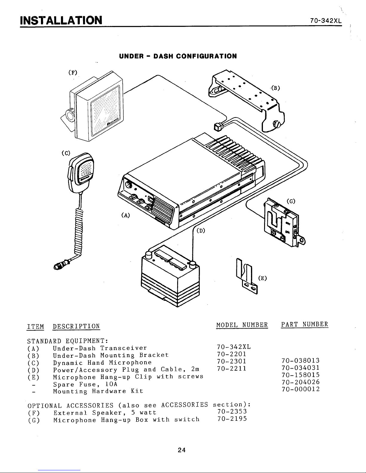
UNDER - DASH CONFIGURATION
ITEM DESCRIPTION
STANDARD EQUIPMENT:
(A)
(B)
(C) Dynamic Hand Microphone
(D)
(E)
-
-
OPTIONAL ACCESSORIES (also see ACCESSORIES
(F)
(G)
Under-Dash Transceiver
Under-Dash Mounting Bracket
Power/Accessory Plug and Cable, 2m
Microphone Hang-up Clip with screws
Spare Fuse, 10A
Mounting Hardware Kit
External Speaker, 5 watt
Microphone Hang-up Box with switch
MODEL NUMBER PART NUMBER
section)
70-2353
70-2195
:
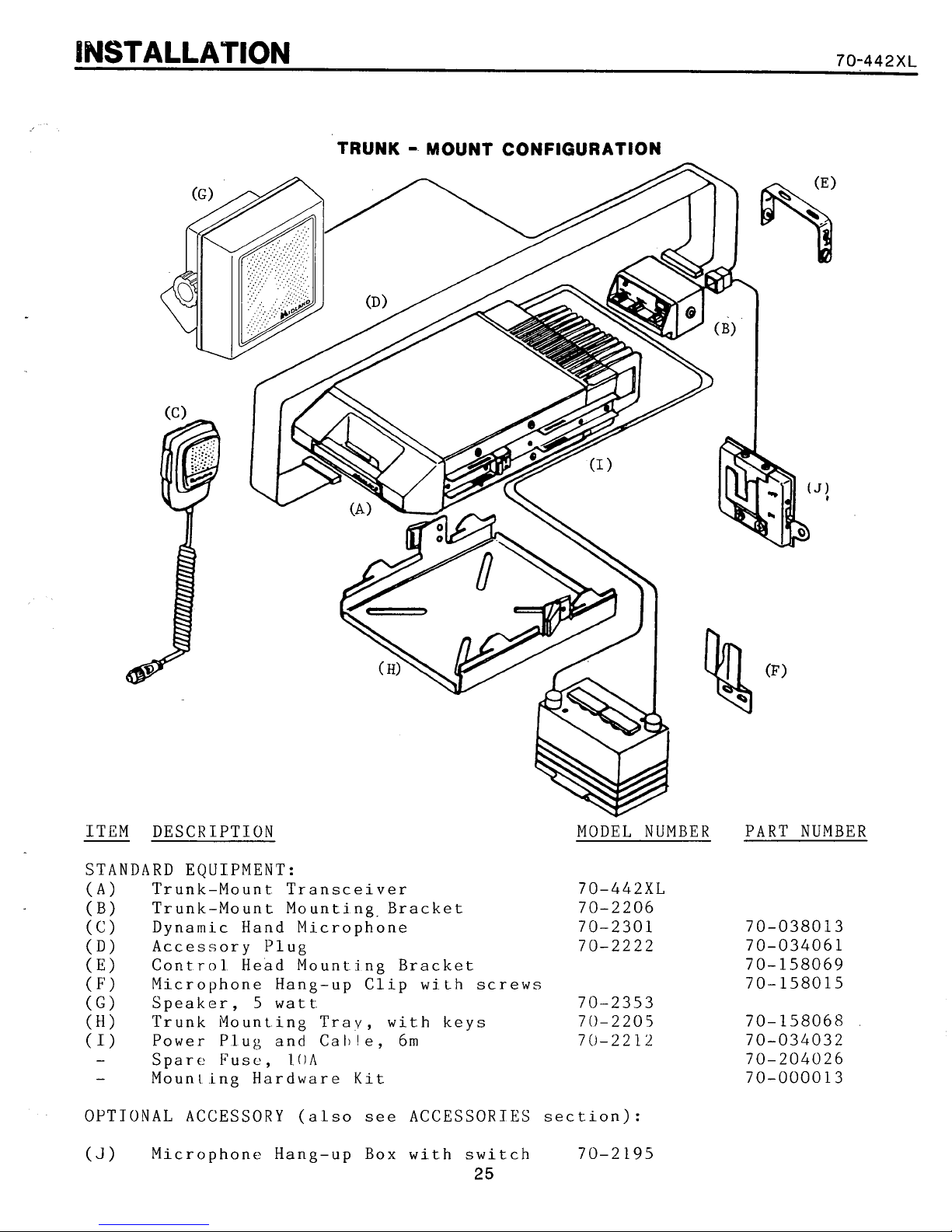
lhlSTALLATlON
70-442XL
TRUNK - MOUNT CONFIGURATION
ITEM DESCRIPTION MODEL NUMBER PART NUMBER
STANDARD EQUIPMENT:
(A) Trunk-Mount Transceiver 70-442XL
(B) Trunk-Mount Mounting.Bracket 70-2206
(C)
(D) Accessory Plug 70-2222
(E)
(F)
(G)
(I)
(I)
-
-
OPTIONAL ACCESSORY (also
(J)
Dynamic Hand Microphone 70-2301
Control Head Mounting Bracket
Microphone Hang-up Clip with
Speaker,
Trunk Mounting Tray, with keys 70-2205
Power Plug and Calde, 6m 70-2212
Spare Fuse,
Mounr ing Hardware
Microphone Hang-up Box with switch 70-2195
5
watt
LOA
Kit
see
ACCESSORIES section):
screws
70-2353
25
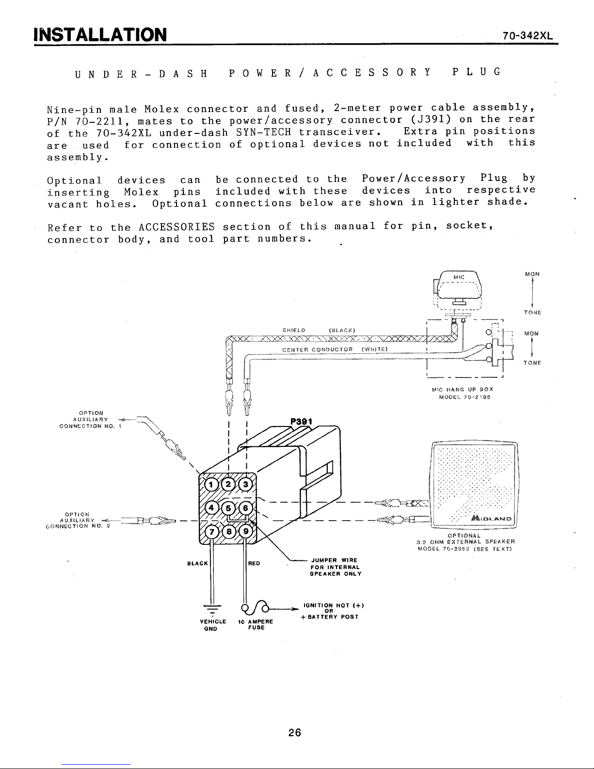
UNDER-DASH POWER/ACCESSORY
PLUG
Nine-pin male Molex connector and fused, 2-meter power cable assembly,
P/N 70-2211, mates to the power/accessory connector (5391) on the rear
of the 70-342XL under-dash SYN-TECH transceiver. Extra pin positions
are used for connection of optional devices not included with this
assembly.
Optional devices can be connected to the Power/Accessory Plug by
inserting Molex pins included with these devices into respective
vacant holes. Optional connections below are shown in lighter shade.
Refer to the ACCESSORIES section of this manual for pin, socket,
connector body, and tool part numbers.
MUM
1
TONE
MON
0
I
TONS
OPTZOW
bU)III.IARY
COHP4ECTIQN
OP'I
10
H
BUXILJhAY
MMEGTIOH
NU.
MO.
*.+.-
2
lNSTALLAVlON
UNDER-DASH POWER CONNECTIONS
The Power/Accessory Cable
connection to the vehicle
are
2
meters
and chassis ground.
long; sufficient for typical connection to a fuse block
is
equipped with two 14 gauge
electrical
system. The unterminated
wires
70-342XL
for
wires
Connect the black
vehicle--DO NOT ATTEMPT TO INSTALL THE TRANSCEIVER
GROUND VEHICLE.
body or chassis often provides an adequate ground if
secure the
Connect the red
electrical system. Because of current requirements, connection to an
existing fused circuit should be avoided to prevent overload of that
fuse. This
penetration and transceiver defect. The connection can be made to
Ignition HOT to switch the transceiver with ignition, or to Battery
HOT to enable the last-selected-channel feature of the transceiver.
In the
Either connection
the red transceiver
EXTERNAL SPEAKER (Models 70-2352, and 70-2353):
Normally, the transceiver internal speaker
ceive audio by the jumper to pins 5 and 6. If one of the MIDLAND
external speakers
to disable the internal speaker and the two wires from the external speaker must connect to pins
Power Speaker
tor (white) must be connected to pin 6, and the shield (black) to
pin
wire
wire
latter
4.
to
wire
case,
wire
A
large bolt that
it.
to the positive
has
is
wire
UNDER-DASH OPTIONAL CONNECTIONS
is
to the negative
screws
(+),
its
own in-line fuse for protection against
the transceiver must be turned off separately.
usually available in the vehicle fuse block ,if
is
terminated with an appropriate lug.
is
to be utilized, the jumper must be removed
4
to be connected,
(-)
chassis ground of the
IN
A
POSITIVE
into the
or Hot side of the vehicle
and
6.
its
input cable center conduc-
metallic
a
lug
is
connected to
NOTE: If the 70-2352
vehicle
is
used to
wire
re-
HANG-UP BOX (Model 70-2195):
If the CTCSS feature
70-2195 Microphone Hang-up contact/switch-box usually
led to unmute CTCSS squelch when the microphone
center conductor of the shielded hang-up box cable connects to
3,
pin
option board within the transceiver must also be removed.
AUXILIARY DEVICES:
Pins
with certain opticnal features. Wiring details for these
found in the respective literature for the option.
the shield to pin 2. Jumper JP2 on the 70-21028 CTCSS
1
and 8 are available for auxiliary connections necessary
is
included in the transceiver, the optional
is
instal-
is
lifted. The
are
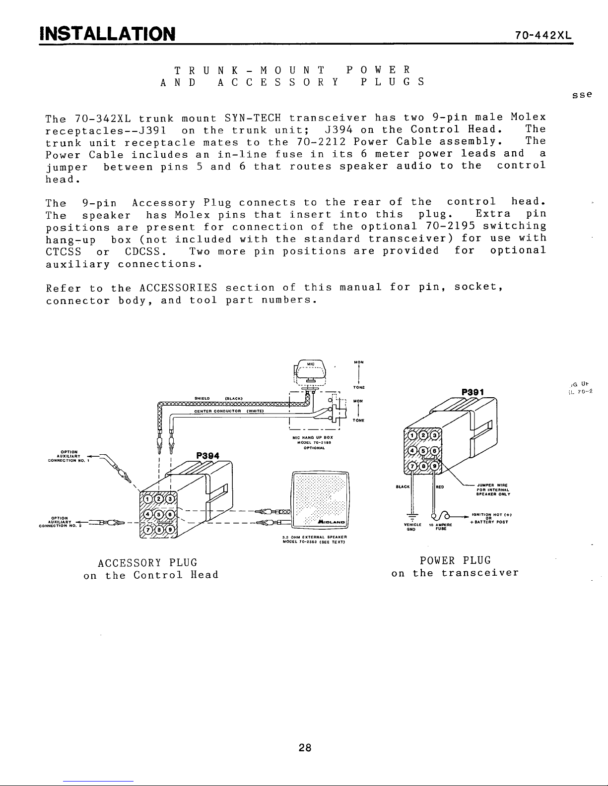
TRUNK-MOUNT POWER
AND
ACCESSORY PLUGS
The 70-342XL trunk mount SYN-TECH transceiver has two 9-pin male Molex
receptacles--J391 on the trunk unit; 5394 on the Control Head. The
trunk unit receptacle mates to the 70-2212 Power Cable assembly. The
Power Cable includes an in-line fuse in
its
6
meter power leads and
a
jumper between pins 5 and 6 that routes speaker audio to the control
head.
The 9-pin Accessory Plug connects to the rear of the control head.
The speaker has Molex pins that insert into this plug. Extra pin
positions
are
present for connection of the optional 70-2195 switching
hang-up box (not included with the standard transceiver) for use with
CTCSS or CDCSS. Two more pin positions are provided for optional
auxiliary connections.
Refer to the ACCESSORIES section of this manual for pin, socket,
connector body, and tool part numbers.
OPTION
AUXILIARV
COHllECIlOW NO
OPIlOll
AUXILIARY
CONWECTlOW NO.
C
2
ACCESSORY PLUG
on the Control Head
WIC
HANO UP
UOOEL
5.2
OHM
EXTERNAL
UOOEL
70-2319 (SEE TEXT)
70-2101
BOX
SPEAKER
TONE
'
r
TOHE
I I
8JL-y;::;;;;;)
VEHICLE
10
AMPERE
(1~0 FUME
POWER PLUG
on the transceiver
 Loading...