

Midland SP-8, SPD-8, SP-10, SPD-10 Service Manual
Model SP-8 & 10
SP-8 &10 Operation, Parts & Service Manual
Midland Machinery Co., Inc.
101 Cranbrook Ext.
Tonawanda, NY 14150
Phone: 716-692-1200
Fax: 716-692-1206
www.midlandmachinery.com
Revision July 2012
www.roadwidener.com
Machine Serial Number : ______________
1


Model SP-8 & 10
Contents
1. IntroduCtIon And WArrAnty .................................................................... 2
1.1 Introduction ...................................................................................................... 2
1.2 Serial Number .................................................................................................. 2
1.3 Warranty ........................................................................................................... 3
1.4 Engine Warranty .............................................................................................. 3
2. Component IdentIfICAtIon .......................................................................... 4
2.1 Overall Machine ............................................................................................... 4
2.2 Operators Console .......................................................................................... 5
3. speCIfICAtIons ........................................................................................... 6
3.1 SP-8/SPD-8 Specifications .............................................................................. 6
3.2 SP-10/SPD-10 Specifications .......................................................................... 6
4. sAfety ...................................................................................................... 7
4.1 Safety Alert Symbol And Signal Words ......................................................... 7
4.2 Hazards ............................................................................................................. 7
4.2.1 mAIntenAnCe ..................................................................................................................... 7
4.2.2 Burn preventIon ............................................................................................................... 7
4.2.3 pressurIzed HydrAulIC fluId And GreAse ......................................................................... 8
4.2.4 HAzArdous CHemICAls ....................................................................................................... 8
4.2.5 fIre or explosIon preventIon ......................................................................................... 8
4.3 Operation And Maintenance ........................................................................... 8
4.3.1 CAlIfornIA proposItIon 65 WArnInG ................................................................................ 10
4.3.2 prepAre for emerGenCIes ............................................................................................... 10
4.3.3 do not AlloW rIders ..................................................................................................... 11
4.3.4 AvoId poWer lInes ......................................................................................................... 11
4.4 Hazards From Modifying Equipment ............................................................11
4.5 Safety Warning Labels .................................................................................. 12
5. operAtIon ............................................................................................... 18
5.1 Operational Safety ......................................................................................... 18
5.2 Startup Procedure ......................................................................................... 18
5.3 Strike-Off Blade Setup ................................................................................... 19
5.3.1 posItIon BlAde .............................................................................................. 19
5.3.2 CHAnGe BlAde lenGtH ..................................................................................................... 22
5.4 Push Roller Setup .......................................................................................... 24
5.4.1 pIvot pIn loCAtIon .......................................................................................................... 24
5.4.2 pusH roller dIstAnCe setup .......................................................................................... 25
5.4.3 HydrAulIC pusH roller dIstAnCe setup .......................................................................... 26
5.5 Set Hopper Gates ........................................................................................... 26
www.roadwidener.com
I

Model SP-8 &10
5.6 Operation ........................................................................................................ 27
5.7 Side Changeover For Material Discharge And Blade ................................. 28
5.7.1 sIde CHAnGeover for mAterIAl dIsCHArGe ...................................................................... 28
5.7.2 BlAde sIde CHAnGeover ................................................................................................... 29
5.7.3 HydrAulIC extensIon CHAnGeover .................................................................................... 31
5.8 Loading For Transport................................................................................... 34
6. servICe And mAIntenAnCe ...................................................................... 36
6.1 Service Intervals ............................................................................................ 36
6.2 Drive Axle And Transmission Lubrication ................................................... 38
6.3 Conveyor Belt ................................................................................................ 39
6.3.1 Adjust Conveyor Belt tensIon ....................................................................................... 39
6.3.2 replACe Conveyor Belt .................................................................................................. 40
6.3.3 Conveyor Belt mAIntenAnCe ........................................................................................... 45
6.4 Hydraulic System Flushing Procedure ........................................................ 46
6.4.1 flusH Conveyor system ................................................................................................. 47
6.4.2 flusH trACtIon drIve system ......................................................................................... 51
6.4.3 flusH Conveyor And trACtIon drIve system .................................................................. 52
7. revIsIon reCords ................................................................................... 53
7.1 Revision Record By Serial Number ............................................................. 53
8. fInAl AssemBly ....................................................................................... 54
8.1 Final Assembly (Dual Sided) ......................................................................... 54
8.1.1 spd-8-001 rev-d (spd-8, duAl sIded) ........................................................................ 55
8.1.2 spd-10-001 rev-f (spd-10, duAl sIded) .................................................................... 55
8.2 Final Assembly (Single Sided) ...................................................................... 56
8.2.1 sp-8-001 rev-H (sp-8, sInGle sIded) .......................................................................... 57
8.2.2 sp-10-001 rev-f (sp-10, sInGle sIded) ........................................................................ 57
9. CHAssIs AssemBly ................................................................................... 58
9.1 Chassis Assembly (SP-8 & SPD-8), SP-005 Rev-F ...................................... 59
9.2 Chassis Assembly (SP-10 & SPD-10), SP-395 Rev-F .................................. 61
9.3 Manual Shift Assembly SP-534 Rev-A ......................................................... 62
9.4 Trailer Axle And Brake Assembly SP-144 Rev-C ........................................ 64
9.4.1 InstruCtIons for BrAke yoke InstAllAtIon And Adjustment: .......................................... 65
10. Conveyor And Hopper AssemBly ......................................................... 66
10.1 Conveyor And Hopper Assembly, Dual Sided, SPD-808 .......................... 66
10.2 Conveyor And Hopper Assembly, Single Sided, SP-808 .......................... 68
10.3 Adjustable Discharge Gate Assembly, SP-276 Rev-A .............................. 70
10.4 Deflector Assembly, SP-717 Rev-A ............................................................ 71
10.5 Bib Assembly, SP-718 ................................................................................. 72
II
www.roadwidener.com

Model SP-8 & 10
10.6 Push Roller Assembly SP-151 Rev-A ......................................................... 73
11. BlAde And Column AssemBly ............................................................... 74
11.1 Blade And Column Assembly SP-8/SPD-8 .................................................. 74
11.1.1 BlAde And Column AssemBly, rIGHt sIde, sp-579 rev-A ............................................. 74
11.1.2 BlAde And Column AssemBly, left sIde, sp-593 rev-A ............................................... 76
11.2 Blade And Column Assembly SP-10/SPD-10 ............................................. 78
11.2.1 BlAde And Column AssemBly, rIGHt sIde, sp-420 rev-B ............................................. 78
11.2.2 BlAde And Column AssemBly, left sIde, sp-588 rev-A ............................................... 80
11.3 Hydraulic Blade Extension Installation For SP-8, SP-751 ........................ 82
11.4 Hydraulic Blade Extension Installation For SP-10, SP-752 ...................... 83
11.5 Hydraulic Blade Extension Assembly, SP-470 Rev-A ............................... 84
11.6 Adjustable Edger Plate Assembly , SP-744 Rev-A .................................... 85
12. enGIne And Controls AssemBly ............................................................ 86
12.1 Engine And Controls Assembly SP-8/SPD-8 ............................................. 86
12.2 Engine And Controls Assembly SP-10/SPD-10 ......................................... 88
13. eleCtrICAl InstAllAtIon ........................................................................ 90
13.1 Electrical Install’n, Standard Config’n, Single Sided, SP-772 Rev-A ...... 90
13.2 Electrical Installation, Optional Neutral Position Brake Switch Safety .. 93
13.3 Electrical Installation, Optional Dual Discharge System ........................ 94
13.4 Electrical Installation, Other Options ........................................................ 96
13.5 Electrical Installation, Optional Auto Grade And Slope (Single Sided) . 98
13.6 Electrical Installation, Optional Auto Grade And Slope (Dual Sided) .. 100
13.7 Electrical Installation, Diode Box Assembly (Single Sided) SP-2161 ... 102
13.8 Electrical Installation, Diode Box Assembly (Dual Sided) SP-2162 ...... 104
14. optIonAl lIGHt pACkAGe .................................................................... 106
14.1 Optional Light Package Schematic SP-2065 Rev-A ................................ 106
14.2 Optional Strobe Light Only Schematic SP-2065 Rev-A .......................... 109
15. operAtor Console AssemBly ............................................................. 110
15.1 Operator Console Assembly (Single Sided) SP-1355 Rev-B ..................111
15.2 Operator Console Assembly (Dual Sided) SPD-1355 Rev-B ...................111
16. HydrAulIC InstAllAtIon ....................................................................... 112
16.1 Hydraulic Installation SPD-8, SPD-10 (Dual Sided), SP-770 Rev-C .......112
16.2 Hydraulic Installation SP-8, SP-10 (Single Sided), SP-769 Rev-C ..........118
17. nAmeplAte And deCAl loCAtIons ........................................................ 124
www.roadwidener.com
III

Model SP-8 &10
18. optIons .............................................................................................. 130
18.1 Hydraulic Push Roller Assembly, SP-711 ................................................ 130
18.1.1 HydrAulIC InstAllAtIon, sp-707 rev-A ....................................................................... 131
18.1.2 HydrAulIC CylInder InstAllAtIon, sp-708 rev-A ........................................................ 131
18.1.3 eleCtrICAl InstAllAtIon, sp-866 rev-B ...................................................................... 132
18.2 Diesel Washdown System, SP-273 ........................................................... 134
18.3 Trench Box Assembly ............................................................................... 136
18.3.1 trenCH Box AssemBly sA/sp duAl sIded, sA-1513 rev-A ........................................ 136
18.3.2 trenCH Box AssemBly sA/sp sInGle sIded, sA-726 rev-B ........................................ 137
19. oem Component pArts And servICe InformAtIon ............................... 139
IV
www.roadwidener.com

Model SP-8 & 10
sp-8 &10 operAtIon, pArts & servICe mAnuAl
www.roadwidener.com
1
Model SP-8 &10
1. IntroduCtIon And WArrAnty
1.1 IntroduCtIon
Congratulations on your purchase of the Midland
Machinery SP machine. This SP machine has
been designed and manufactured to the strictest
specications. It is our utmost desire that you achieve
success and are rewarded years of service from your
equipment purchase.
Midland Machinery reserves the right to change,
improve, modify or expand features of this equipment
at any time. Specications, models, or equipment are
subject to change without notice, and without incurring
any obligations to change, improve or expand features
of previously delivered equipment. Because of
variations in optional equipment and continued design
improvement, certain information contained within this
manual may not apply.
Carefully examine your machine upon receipt. Report
any damage immediately to the freight carrier and
register any claim. Should any material or manufacturing
defects be discovered, report your ndings to our
service department along with the model, serial number
and date of purchase. We want to know that you are
satised with the machine. As always, we welcome
input on how our products can be improved to serve
you better.
Read and understand this manual before using your
machine and follow all of the safety instructions. Keep
this manual with your machine at all times.
Some components may have separate operation and
maintenance manuals. Where this manual indicates
that you should read another manual, and you do
not have that manual, contact Midland Machinery for
assistance.
This manual explains the operation and routine
maintenance of the SP machine. It does not instruct
you how to transport, travel and/or operate on specic
roadways or terrain.
This Operator’s Manual does not replace, nor does its
use release the operator from observing all safety or
operating limitations as well as any applicable federal,
state, provincial or local regulations.
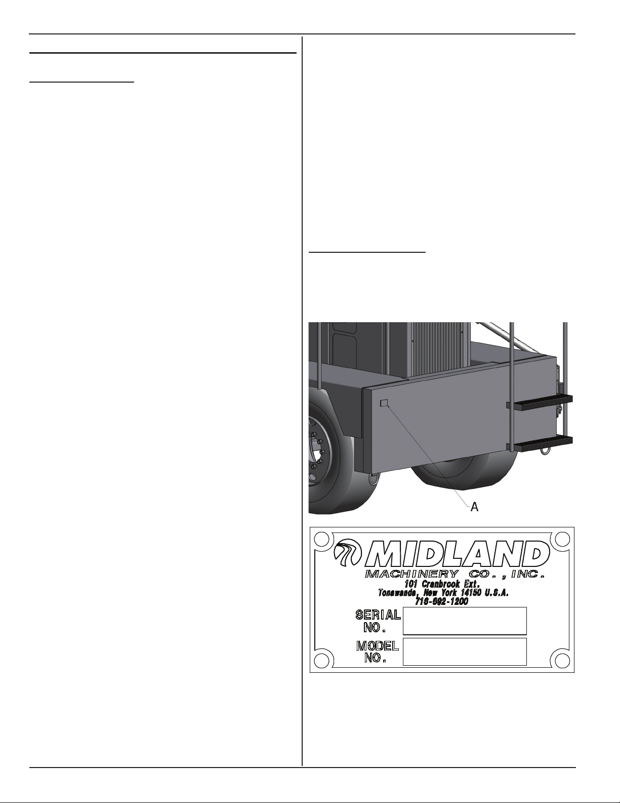
1.2 serIAl numBer
The serial number plate (A) is located on left rear
corner of the machine.
Information furnished in this manual does not include
all of the details of design, production, or variations
of the equipment. It does not cover all the possible
contingencies, which may arise during operation,
setup, or maintenance. Should special problems
arise, or further information be desired, please contact
Midland Machinery. This manual is provided to the SP
owner to assist in the safe operation and maintenance
of the equipment.
The text contained in this manual is for current
production models. Some instructions and maintenance
procedures may not apply to your specic unit.
Equipment modications from original design and
specications are strictly prohibited. Modications may
compromise safe operation of the machine, subjecting
users to serious injury or death and may void any
remaining warranty.
2
www.roadwidener.com
1.3 WArrAnty
Model SP-8 & 10
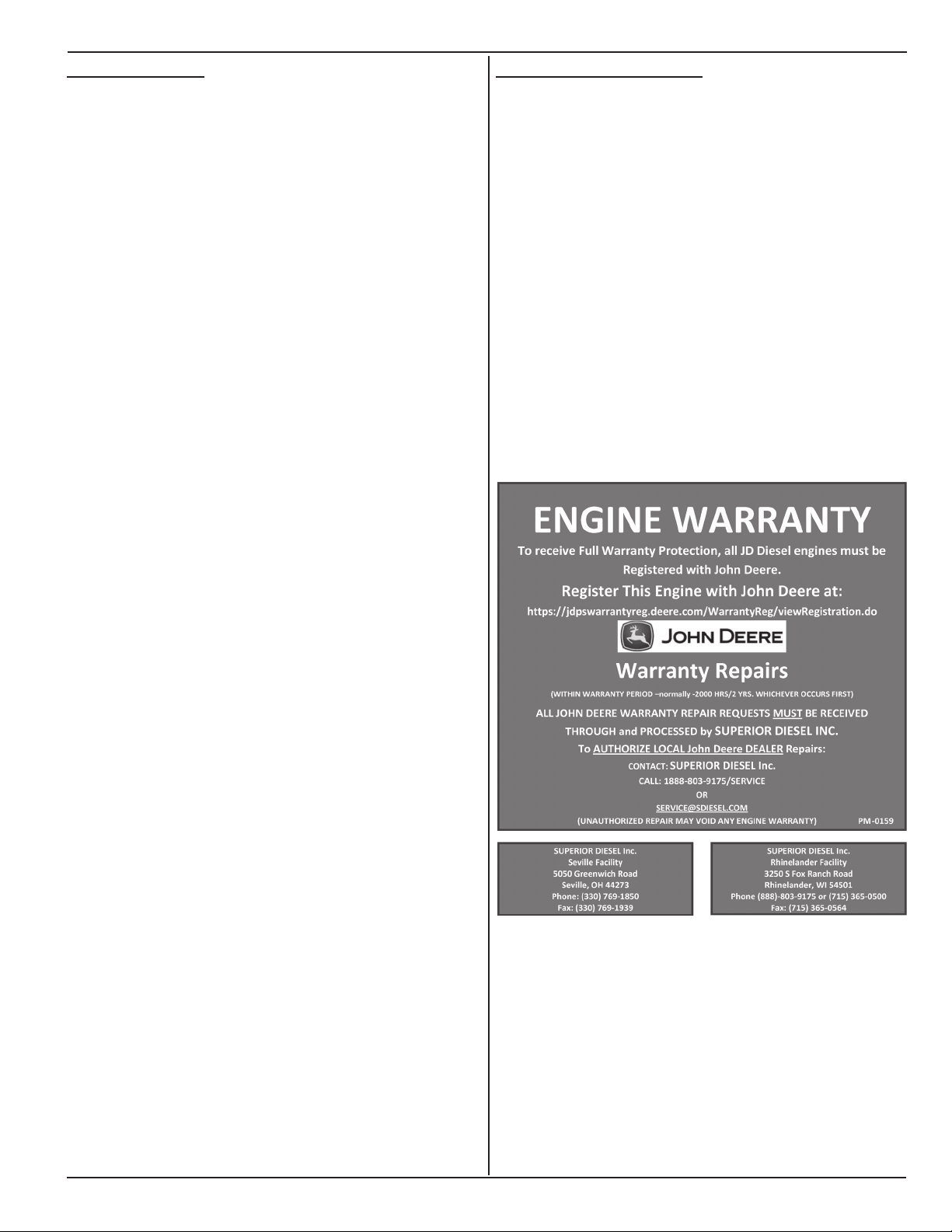
1.4 enGIne WArrAnty
Midland warrants to the original purchaser only,
that each part of the Road Building Machine, or
components, or the other manufactured items, sold
herein, under normal use and service, shall be free
from defects in workmanship and material for 180 days
or 500 working hours, from initial start-up, whichever
occurs rst, except that this warranty shall not apply
to tires, engines, batteries, manufactured hydraulic
components, which items shall be subject only to the
original manufacturer’s warranty. No adjustment shall
be made for defective items unless notice is given in
writing within ten days after the defect is noted and the
equipment is immediately taken out of service. Use of
equipment thereafter shall constitute acceptance and
waiver of the alleged defects.
This warranty shall be fullled by Midland repairing or
replacing at its factory, products or parts that have been
returned to it with transportation charges prepaid and
that appear to its satisfaction to have been defective in
workmanship or material.
To receive full warranty protection, All John Deere
engines must be registered with John Deere company.
To register your engine with John Deere, please
visit the website: https://jdpswarrantyreg.deere.com/
WarrantyReg/viewRegistration.do.
Warranty Period is normally 2000 engine hours or 2
years from the date of purchase which ever occurs rst.
ALL WARRANTY REPAIR REQUESTS MUST BE
RECEIVED THROUGH AND PROCESSED BY
SUPERIOR DIESEL INC.
TO AUTHORIZE LOCAL JOHN DEERE DEALER
REPAIRS, CONTACT SUPERIOR DIESEL INC AT
PHONE NUMBER 1-888-803-9175/SERVICE OR
THROUGH E-MAIL AT SERVICE@SDIESEL.COM.
THE FOREGOING SPECIFIC WARRANTY IS IN
LIEU OF ANY OTHER EXPRESSED OR IMPLIED
WARRANTIES INCLUDING ANY IMPLIED WARRANTY
OF MERCHANTABILITY OR FITNESS FOR A
PARTICULAR USE, AND ANY OTHER OBLIGATION
ON PART OF MIDLAND. MIDLAND SHALL NOT BE
RESPONSIBLE UNDER THIS WARRANTY FOR
ANY LOSS OF USE OF THE VEHICLE, LOSS OF
TIME, INCONVENIENCE, COMMERCIAL LOSS OR
CONSEQUENTIAL DAMAGE.
NO AGENT, EMPLOYEE OR REPRESENTATIVE OF
MIDLAND HAS ANY AUTHORITY TO BIND MIDLAND
TO ANY AFFIRMATION, REPRESENTATION OR
WARRANTY CONCERNING THE MACHINE SOLD
UNDER THIS CONTRACT NOT STATED WITHIN, AND
UNLESS AN AFFIRMATION, REPRESENTATION OR
WARRANTY MADE BY AN AGENT, EMPLOYEE OR
REPRESENTATIVE IS SPECIFICALLY INCLUDED
WITHIN THIS WRITTEN AGREEMENT, IT SHALL
NOT BE ENFORCEABLE AGAINST MIDLAND.
UNAUTHORIZED REPAIR MAY VOID ANY ENGINE
WARRANTY.
www.roadwidener.com
3
Model SP-8 &10
2. Component IdentIfICAtIon
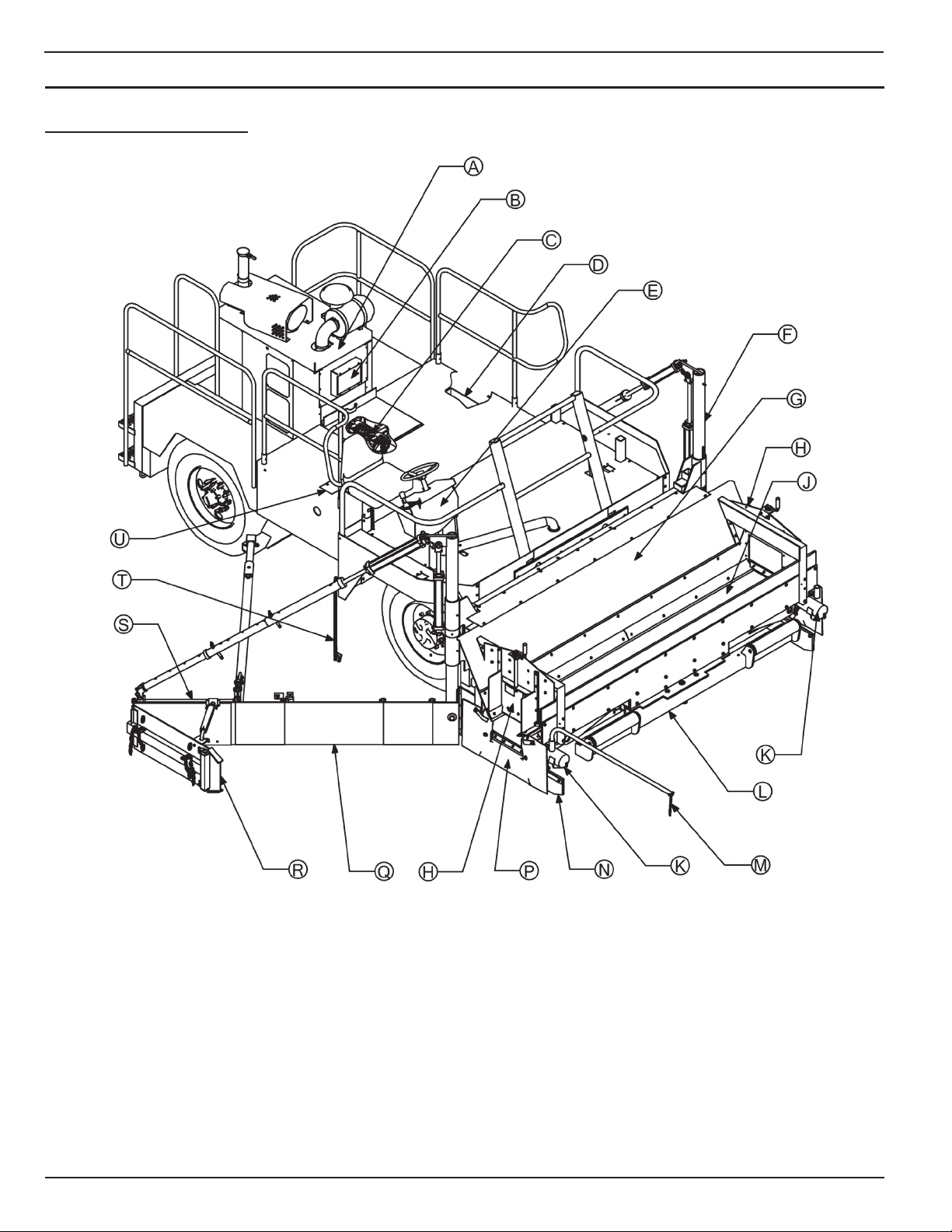
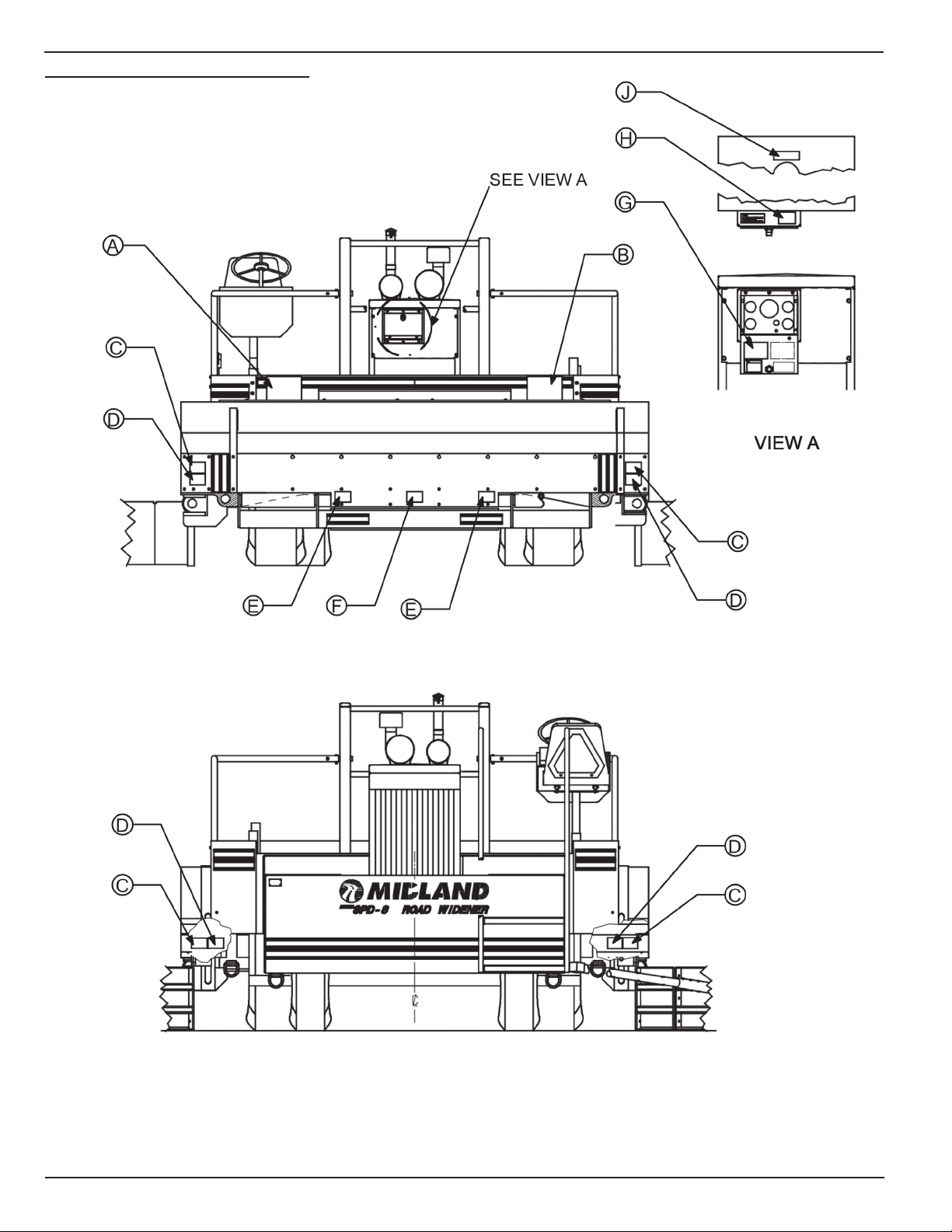
2.1 overAll mACHIne
A - Engine
B - Engine controls
C - Hydraulic Pumps
D - Manual Pack
E - Operator Console
F - Blade And Column Assembly (L/S)*
G - Conveyor And Hopper Assembly
H - Discharge Gate Assembly**
J - Conveyor Belt
K - Conveyor Motor
* Available only in dual side configuration
** Available as option
4
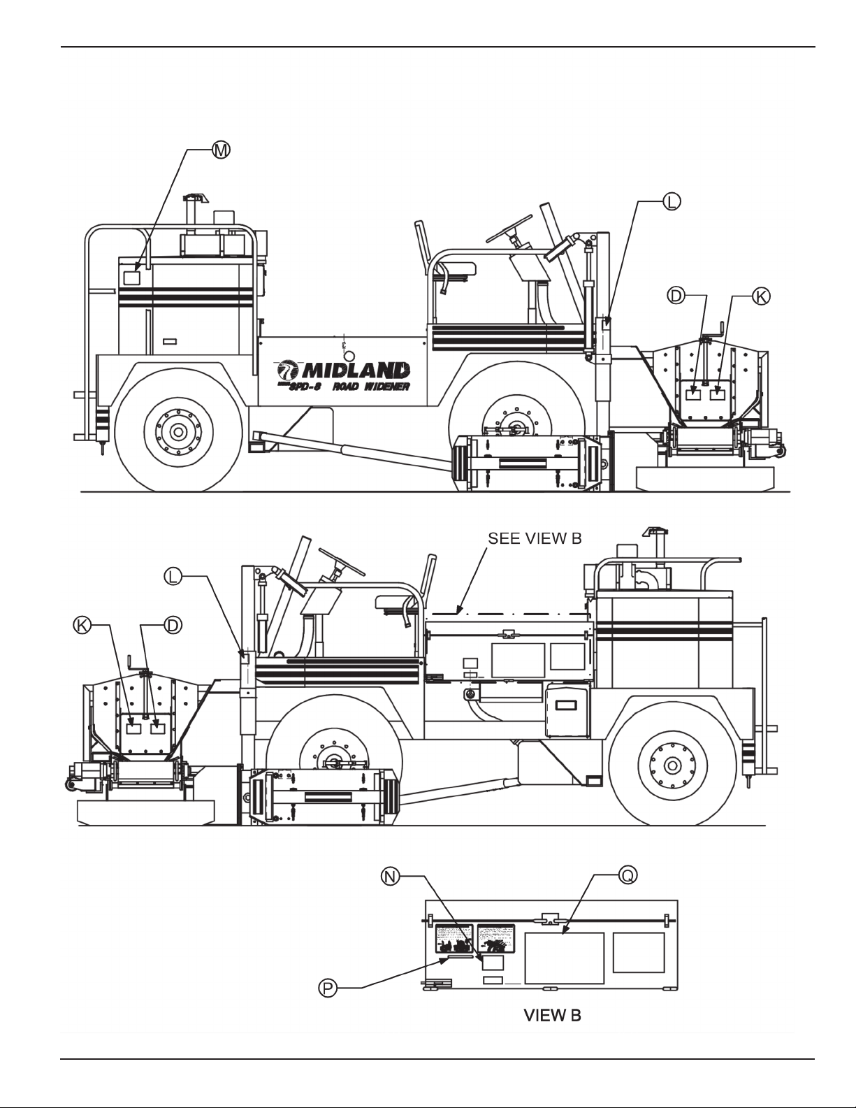
L - Push Roller Assembly
M - Guide Rod Assembly
N - Deector Assembly
P - Bib Assembly
Q - Blade And Column Assembly (R/S)
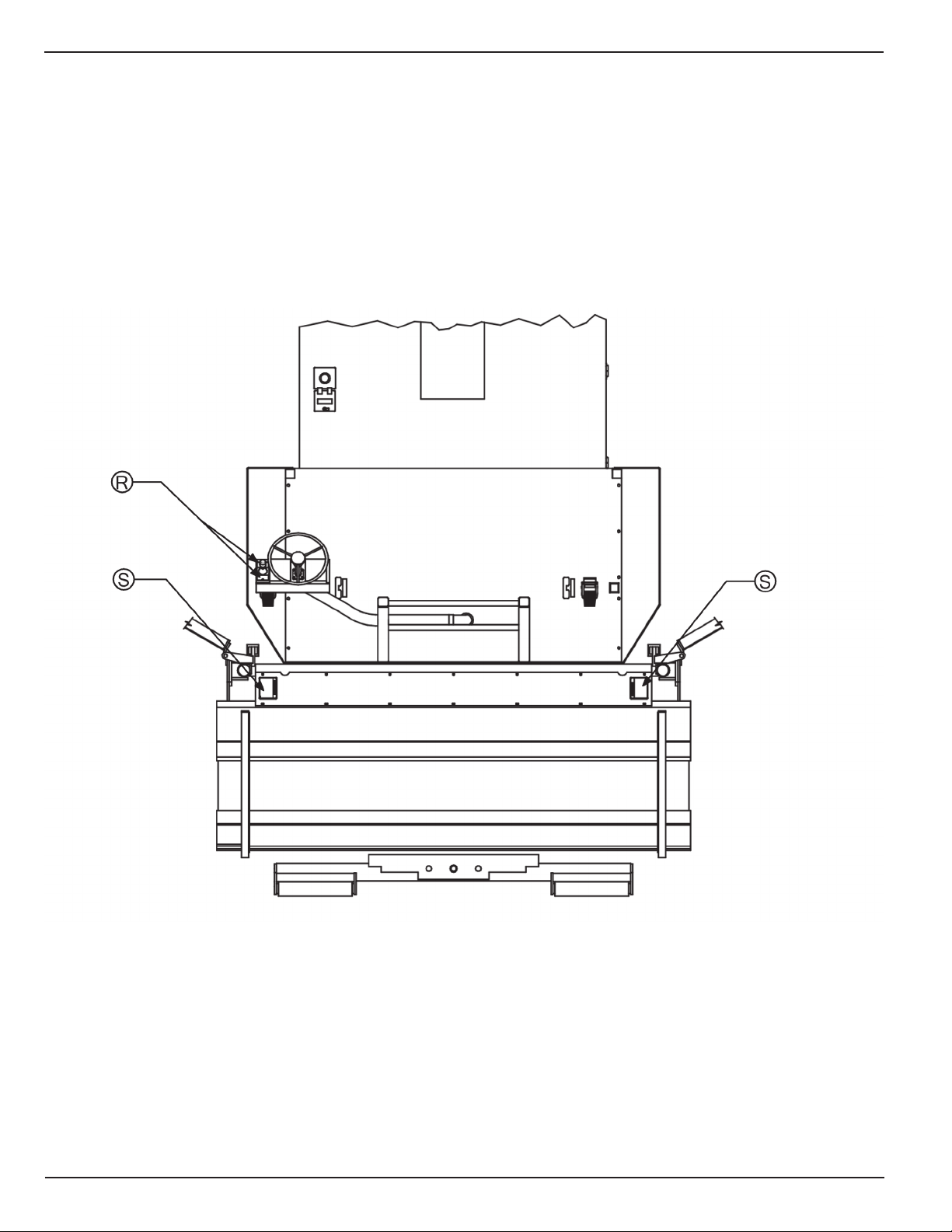
R - Outer Edger Assembly
S - Hydraulic Blade Extension**
T - Blade Restraint Assembly
U - Hydraulic Tank
www.roadwidener.com
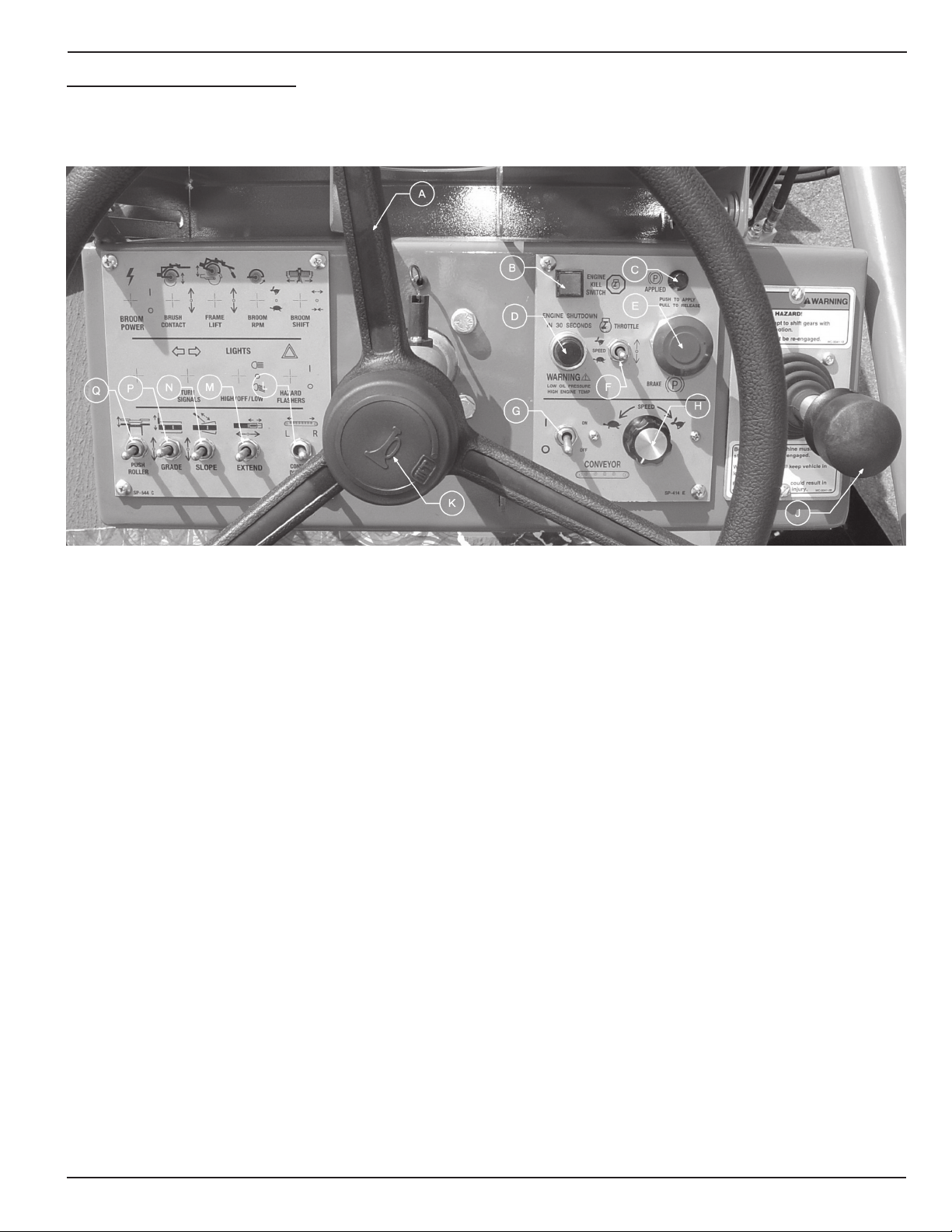
2.2 operAtors Console
Model SP-8 & 10
A - Steering Wheel
B - Engine Kill Switch
C - Parking Brake Applied Indicator
D - Dual Alarm
E - Parking Brake (E-Stop) Button
F - Engine Throttle Switch
G - Conveyor On/Off Switch
H - Conveyor Speed Controller
* Available only in dual side configuration
** Available as option
J - Travel Controller
K - Horn Button
L - Conveyor Direction Switch*
M - Blade Hydraulic Extension Switch**
N - Blade Slope Switch
P - Blade Grade Switch
Q - Hydraulic Push Roller Switch**
www.roadwidener.com
5

Model SP-8 &10
3. speCIfICAtIons
3.1 sp-8/spd-8 speCIfICAtIons
3.2 sp-10/spd-10 speCIfICAtIons
Dimensions-
Length: 19 ft.
Width: Travel - 11 ft. 2 in.
Track (Front) - 80 in.
Track (Rear) - 60 in.
Turn Radius : 15 ft.
Height: 7 ft. 10 in.
Weight: 19,000 lbs.
Wheelbase: 98 in.
Tires: Front : 2 x 425/65R/22.5 Pneumatic
Rear : 2 x 11 R22.5 Pneumatic
Engine/Drive -
John Deere Diesel Model 4045D Tier III 80 hp
Front Wheel Drive, Front Wheel Steering.
Two Speed Hydrostatic Transmission.
Hydraulic Service Brakes
SAHR Emergency/ Parking Brake.
Travel Speed: 0 - 11 mph.
Working Speed: 0 - 150 ft/min.
Strike-Off Blade -
4 - 8 ft. Maximum Spread Width.
18 in. Tall, 1 ft. & 2 ft. long, Modular Blade Sections.
Optional 2 - 4 ft. Hydraulic Extension Section.
Adjustable Height Outer Edger.
Hydraulic Grade Control - 12 in. Above / Below.
Hydraulic Slope Control +/- 16%.
Dimensions-
Length: 19 ft. 4 IN.
Width: Travel - 11 ft. 2 in.
Track (Front) - 80 in.
Track (Rear) - 60 in.
Turn Radius : 15 ft.
Height: 8 ft. 3 in.
Weight: 27,500 lbs.
Wheelbase: 98 in.
Tires: 4 x 425/65R/22.5 Pneumatic
Engine/Drive -
John Deere Diesel Model 4045T Tier III 100 hp Turbo
Charged
Front Wheel Drive, Front Wheel Steering.
Two Speed Hydrostatic Transmission.
Hydraulic Service Brakes
SAHR Emergency/Parking Brake.
Travel Speed: 0 - 11 mph.
Working Speed: 0 - 150 ft/min.
Strike-Off Blade -
1-10 ft. Maximum Spread Width.
18 in. Tall, 1 ft. & 2 ft. long, Modular Blade Sections.
Optional 2 - 4 ft. Hydraulic Extension Section.
Adjustable Height Outer Edger.
Hydraulic Grade Control - 12 in. Above / Below.
Hydraulic Slope Control +/- 16%.
Receiving Hopper -
11 ft. 2 in. Width, Adjustable Discharge Gates.
3 cubic yard Capacity
Conveyor -
Right or Left Hand Discharge.
Heat And Oil Resistant Conveyor Belt
Chain Driven 18 in. Conveyor Belt with
Variable Speed Hydraulic Drive to 450 TPH Output.
Push Rollers -
Extendable, Oscillating, Self Cleaning
Specications subject to change without notice.
6
Receiving Hopper -
11 ft. 2 in. Width, Adjustable Discharge Gates.
3 cubic yard Capacity
Conveyor -
Right or Left Hand Discharge.
Heat And Oil Resistant Conveyor Belt
Chain Driven 18 in. Conveyor Belt with
Variable Speed Hydraulic Drive to 450+ TPH Output.
Push Rollers -
Extendable, Oscillating, Self Cleaning
Specications subject to change without notice.
www.roadwidener.com

Model SP-8 & 10
4. sAfety
4.1 sAfety Alert symBol And sIGnAl Words
This manual covers the SP-8, SPD-8, SP-10 and
SPD-10 machines produced by Midland Machinery
(henceforth mentioned as “SP” or “SP machine”, unless
required otherwise). Before setting up, operating or
servicing SP machine, you must read, understand
and follow the instructions and safety warnings in this
manual. Your machine may not be equipped with some
of the optional equipment shown in the illustrations in
this manual.
All personnel that will be operating, maintaining
and working around the SP machine must read and
understand these documents before interacting with
the SP.
NEVER ALLOW ANYONE TO OPERATE THIS
EQUIPMENT WITHOUT PROPER TRAINING!
If you have any safety concerns or questions that are
not covered by this manual, please contact Midland
Machinery at 1-716-692-1200.
^
^ CAUTION
CAUTION - Indicates a hazardous situation,
which, if not avoided, could result in minor
or moderate injury.
NOTICE
NOTICE - Indicates a situation that could
result in damage to the equipment or other
property.
4.2 HAzArds
SP machine is a complex machines and its operation
requires a high level of machine knowledge and skill.
Safe use is dependant on correct operation and proper
maintenance.
4.2.1 mAIntenAnCe
Before servicing machine:
1. Park on a rm level surface.
2. Apply parking brakes.
3. Turn engine off, close and lock control panel
cover.
4. Chock tires.
5. Place a “Do Not Operate” tag on operators
console.
This symbol means ATTENTION! BECOME ALERT!
YOUR SAFETY IS INVOLVED!
The level of risk is indicated by the following signal
words:
^ DANGER
DANGER - Indicates a hazardous situation,
which, if not avoided, WILL result in death
or serious injury.
^ WARNING
WARNING - Indicates a hazardous
situation, which, if not avoided, could
result in death or serious injury.
Read and understand this manual. If you do not
understand any part of this manual, contact your
dealer.
Always wear face or eye protection, safety shoes, and
other protective items as required.
Do not make unauthorized modications to machine.
Contact your dealer before you weld, cut/drill holes, or
make any other modications to your machine. Always
use Midland Machinery replacement parts.
If you must service machine with engine running, have
someone in constant visual contact who can shut off
engine if necessary.
If you must service machine with an attachment raised,
block attachment up to prevent attachment falling in
case of pressure or power loss.
4.2.2 Burn preventIon
Battery acid causes severe burns. Batteries contain
sulfuric acid. Avoid contact with skin, eyes or clothing.
www.roadwidener.com
7

Model SP-8 &10
• If acid contacts skin: Flush with water. Apply baking
soda or lime to neutralize acid and get immediate
medical attention.
• If acid contacts eyes: Flush with water for 15
minutes and get immediate medical attention.
• If acid is swallowed: Drink large quantities of water
or milk, then drink milk of magnesia, beaten eggs, or
vegetable oil and get immediate medical attention.
Keep battery fully charged to avoid battery freezing. If
battery electrolyte freezes, battery can explode if you
try to charge or jump start the battery.
Explosive release of coolant can cause serious burns.
Turn off engine and let engine cool before removing
coolant cap. Loosen cap to rst stop to relieve pressure
before removing cap completely.
4.2.3 pressurIzed HydrAulIC fluId And GreAse
Hydraulic uid and grease injected into your skin
may cause serious injury or death. Keep your hands
and body away from any pressurized leak. Tighten
connections before applying pressure. Never use your
hand to check for leaks; use a piece of cardboard
or paper. If uid is injected into the skin, it must be
surgically removed within a few hours or gangrene
may result. Get immediate medical attention.
4.2.4 HAzArdous CHemICAls
• When connecting battery cables, connect negative
(-) cable last.
• Do not short circuit battery posts with metal items.
Remove all trash and debris from engine. Do not store
oily rags or ammable materials on or near engine.
Always have a re extinguisher available on machine.
Keep the extinguisher serviced according to
manufacturer’s instructions.
Check for fuel, oil and hydraulic uid leaks. Replace
worn or damaged hoses or lines. Clean up spilled
uids.
4.3 operAtIon And mAIntenAnCe
^ WARNING
Prevent serious injury or death.
Read and understand this manual before
operating machine.
Always stop engine and remove key before
leaving operators console.
Never allow anyone near machine during
operation.
Fluids, lubricants, coolants, can be hazardous. Before
servicing machine, check Material Safety Data Sheet
(MSDS) for each uid or lubricant to understand
the product, safe handling procedures, and rst aid
measures relating to the product. Follow this information
when servicing machine.
Do not drain or pour any uids or lubricants on
ground. Check with local environmental agencies,
recycling centers, or your dealer for correct disposal
information.
4.2.5 fIre or explosIon preventIon
Engine fuel can cause an explosion or re. Do not
service or refuel with engine running or near open
ame. Do not weld or smoke near fuel. Never allow
fuel to spill on hot machine components.
Keep sparks and ames away from batteries to prevent
explosion of hydrogen gas in and near a battery. Other
precautions include:
• When disconnecting battery cables, disconnect
negative (-) cable rst.
8
Travel at a safe speed.
^ WARNING
Crush hazard.
Chock wheels before mechanically
releasing brakes.
Do not operate machine with brakes
mechanically released.
^ WARNING
Carbon monoxide hazard.
Do not operate engine with machine in an
enclosed building or conned area.
Avoid actions or areas that expose you and
others to carbon monoxide.
www.roadwidener.com

Model SP-8 & 10
^ WARNING
Prevent serious injury or death from
moving parts.
Moving parts can crush and dismember.
Do not operate without guards and shields
in place.
Disconnect and lockout power source
before adjusting or servicing.
^ DANGER
Sulfuric acid can cause blindness or
severe burns. When servicing battery:
• Wear appropriate protective equipment.
• No smoking, sparks or ames near
battery.
If sulfuric acid gets on your skin or in your
eyes:
• Immediately ush the affected area with
clean water for 15 minutes.
• Seek immediate medical attention.
^ WARNING
Prevent serious injury or death.
Do not operate, work on or around
machine while under the inuence of
alcohol, drugs or if feeling ill.
^ WARNING
Flammable material. Diesel fuel.
No open ames and no smoking while
fueling.
^ WARNING
Entanglement hazard.
Loose tting clothing and long hair can
become entangled in moving or rotating
parts.
Do not wear loose tting clothing.
Long hair must be tied back or netted.
^ WARNING
Prevent serious injury or death.
Before performing inspections, service or
maintenance:
• Park machine on rm, level surface and
engage parking brake.
• Switch engine off.
• Close and lock control panel cover.
• Chock tires.
^ WARNING
Corrosive chemicals may be present.
Exposure may result in serious injury.
Wear appropriate protective equipment.
Read and follow handling instructions and
MSDS for the chemical.
Keep clear of moving components.
Never operate machine with open or
removed guards or shields.
Observe federal, state/provincial and local safety codes
and regulations that apply to the job site.
^ WARNING
Prevent serious injury or death.
Walk platforms and covers may be
slippery. Keep steps, handrails, and
platform clean.
Use handrails and face machine when
climbing up or down steps. Use three
points of support when climbing up or
down steps.
Use caution while walking on machine to
avoid falling. Do not jump off machine.
www.roadwidener.com
9

Model SP-8 &10
^ WARNING
Noise hazard.
Prolonged exposure to loud noise can
cause impairment or loss of hearing
Operator, workers and bystanders must
use ear protection while machine is in
operation.
^ WARNING
Prevent serious injury or death.
Do not operate with covers, guards or
doors open or removed.
Keep clear of moving components.
Follow lockout procedure before servicing.
^ WARNING
Pressurized uids can penetrate the skin.
Hydraulic hoses can fail from age, damage
and exposure.
Do not search for hydraulic leaks without
body and face protection. A tiny, almost
invisible leak can penetrate the skin,
thereby requiring immediate medical
attention.
Use wood or cardboard to detect hydraulic
leaks, never use your hands.
^ WARNING
Prevent serious injury or death.
Operator must wear seat belt while
operating machine.
^ WARNING
Prevent serious injury or death.
Do not mount or dismount moving
equipment.
Do not enter hopper while machine is
running.
^ WARNING
Prevent serious injury or death.
Hot and high pressure hydraulic oil.
Allow to cool before servicing.
^ WARNING
Pinch point.
Push rollers may move suddenly.
Keep clear during operation.
NOTICE
Dispose of waste properly.
Improper disposal of waste can harm the
environment.
Use leak proof container when draining
uids. Do not use food or beverage
containers.
Contact local environmental or recycling
center for proper way to recycle or dispose
of waste.
4.3.1 CAlIfornIA proposItIon 65 WArnInG
Diesel engine exhaust and some of its constituents are
known to the State of California to cause cancer, birth
defects and other reproductive harm.
Battery posts, terminals and related accessories contain
lead and leads compounds, chemicals known to the
State of California to cause cancer, birth defects and
other reproductive harm. Wash hands after handling.
10
4.3.2 prepAre for emerGenCIes
Be prepared in case of emergencies.
www.roadwidener.com
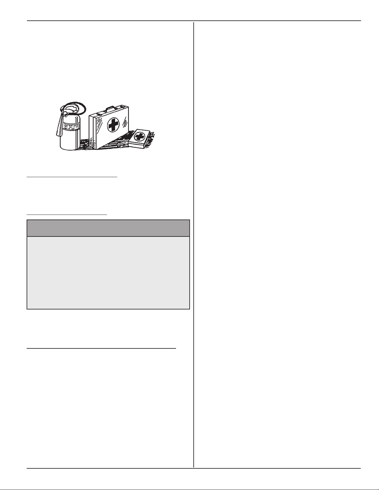
Keep a re extinguisher and rst aid kit close to
machine.
Keep emergency phone numbers in a easy to access
location.
Know your location so emergency services can locate
you if an emergency arises.
4.3.3 do not AlloW rIders
Never allow riders on machine. Machine is equipped to
carry the operator only.
Model SP-8 & 10
4.3.4 AvoId poWer lInes
^ WARNING
Prevent electrocution.
Death or serious injury can result if
equipment comes near or contacts power
lines.
Electrocution can occur without direct
contact.
DO NOT leave operator’s seat if any part of equipment
contacts electric lines or cables.
4.4 HAzArds from modIfyInG equIpment
Do not modify or alter machine. Modifying or altering
may cause machine to be unsafe and will void the
manufacturers’ warranty.
www.roadwidener.com
11
Model SP-8 &10
4.5 sAfety WArnInG lABels
12
www.roadwidener.com
Model SP-8 & 10
www.roadwidener.com
13
Model SP-8 &10
14
www.roadwidener.com
Model SP-8 & 10
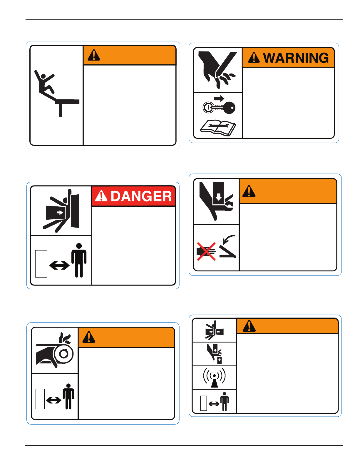
Decal A - WC-0003
Decal B - WC-0004
WARNING
FALL H AZ ARD!
Do not stand in
hopper when engine
is running.
Failure to comply
could result in death
or serious injur y.
WC-0003A
Decal D - WC-0006
Decal E - WC-0007
SEV ER H AZ ARD!
Moving parts can sever.
Do not perform
maintenance on conveyor
with engine running.
Failure to comply could
result in death or serious
injury.
WC-0006A
WARNING
Decal C - WC0020
CRUSH H AZ ARD!
Do not stand in front
of machine when
engine is running.
Failure to comply will
result in death or
serious injury.
WC-0004A
WARNING
ENTANGLEM EN T
HAZ ARD!
Stay clear while conveyor
is in operation.
Failure to comply could
result in death or serious
injury.
WC-0020A
Decal F - WC-0047
CRU SH HAZ ARD!
STAND CLEAR!
Hydraulic cylinder is
operated by remote
control.
Failure to comply could
result in death or serious
injury.
CRU SH HAZARD!
Keep hands clear.
Failure to comply
could result in death
or serious injury.
WC-0007A
WARNING
WC-0047A
www.roadwidener.com
15

Model SP-8 &10
Decal G - WC-0001
Decal H - WC-0052
CAUTION
Before assembling,
operating, cleaning,
lubricating or adjusting
machinery, operator
should read and follow
manufacturer s
instructions.
CAUTION
,
WC-0001A
Decal K - WC-0022
STAND CLEAR!
Material discharge
hopper is operated by
remote control.
Failure to comply may
result in minor or
moderate injury.
Decal L - WC-0012
CAUTION
WC-0022A
WARNING
C RU SH H AZARD!
Decal J - WC-0056
NOI SE H AZARD!
Ear protection
must be worn
when operating
machine.
WC-0052A
Stand clear.
Material discharge area and
strike off blade operated by
remote control.
Failure to comply could
result in death or serious
injury.
Decal M - WC-0053
WC-0012A
WARNING
FALL H AZ ARD !
NO RI DERS!
Machine is to be
operated by one
16
person only.
Failure to comply
could result in death
or serious injury.
www.roadwidener.com
WC-0053
Model SP-8 & 10
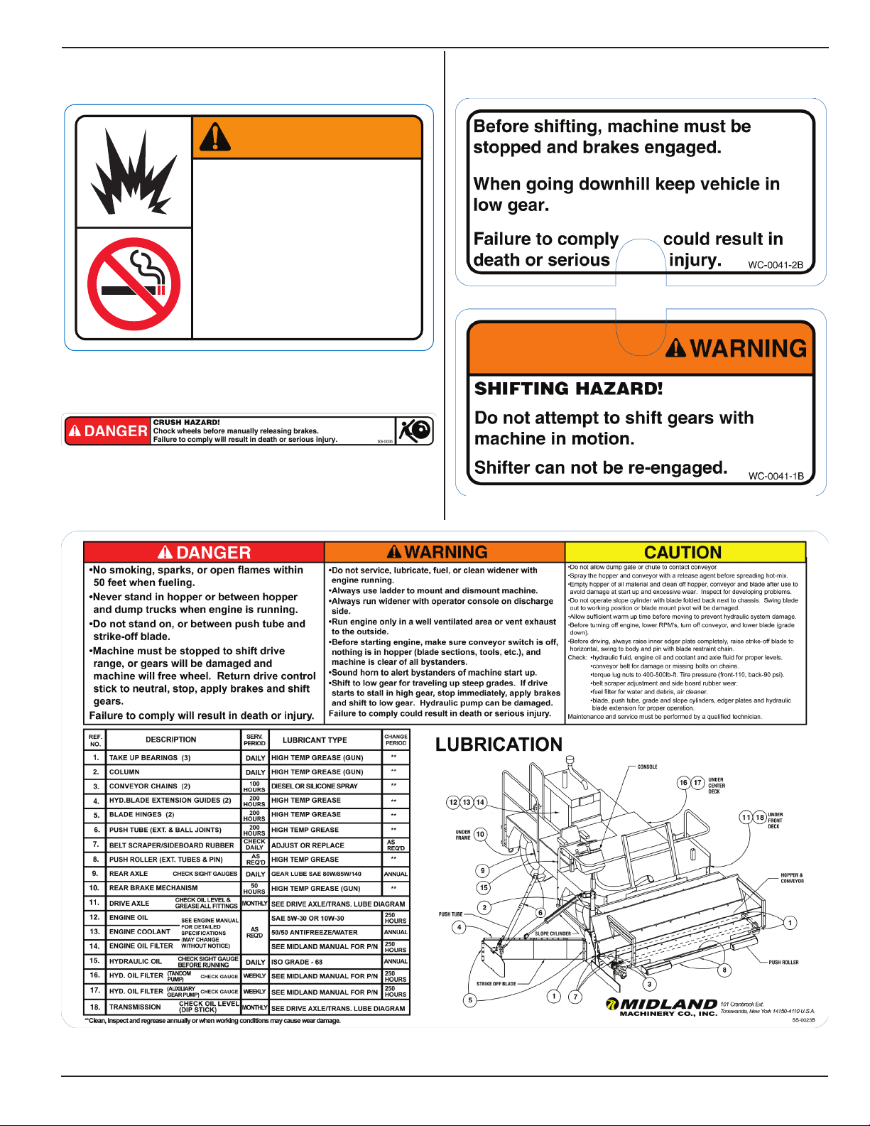
Decal N - WC-0014
Decal P - SS-0035
WARNING
EXPLOSI ON HAZ ARD!
No smoking or open
flame within 50 feet
during fueling or
washdown.
Failure to comply could
result in death or serious
injury.
WC-0014B
Decal R - WC-0041
Decal Q - SS-0035
www.roadwidener.com
17

Model SP-8 &10
5. operAtIon
5.1 operAtIonAl sAfety
^ Keep bystanders away from equipment while in
use.
^ Always wear face or eye protection, ear protection,
safety shoes, and other protective equipment
appropriate for the job.
^ Do not operate, work on or around this machine
while under the inuence of alcohol, drugs or if
feeling ill.
^ Keep clear of moving machinery at all times.
^ Turn off machine before exiting operator station.
^ WARNING
Carbon monoxide hazard.
Do not operate engine with machine in an
enclosed building or conned area.
Avoid actions or areas that expose you and
others to carbon monoxide
^ WARNING
Prevent serious injury or death.
Before performing inspections, service or
maintenance:
• Park machine on rm, level surface and
engage parking brake.
• Switch engine off.
• Close and lock control panel cover.
• Chock tires.
^ You must inspect, maintain and service equipment
regularly for safe and reliable operation.
^ Operate equipment safely. Read and understand
this manual before operating machine.
^ It is your responsibility to operate this machine
safely. You must be familiar with machine and all
safety practices before use.
^ Do not allow untrained or unqualied people to
operate machine.
^ Wear close tting clothing and safety equipment
that is appropriate to the job. Do not wear music
or radio headphones while operating equipment.
5.2 stArtup proCedure
Check the following items before operating machine:
• Check fuel, engine oil, coolant and hydraulic oil
levels. Add uids if low.
• Check conveyor belt for damage or missing parts.
• Check belt scraper adjustment. Adjust if needed.
• Check side board rubber wear. Replace if worn.
• Check engine fuel lter. Drain water or debris.
• Check air lter restriction gauge.
• Inate tires to 120 psi.
• On SP-10 and SPD-10, rear tires are lled with
calcium ballast. Use suitable equipment to inate
tires.
• Tighten wheel lugs to 400-500 lb/ft of torque.
• Inspect tires for signs of wear or damage.
• Check hydraulic components for proper operation.
• Visually inspect engine belts, fan, alternator and
battery.
• Inspect hydraulic hoses for signs of wear or
damage.
• Verify all guards, covers, shields and access doors
are installed and properly latched.
• Check for oil and coolant leaks.
NOTICE
Prevent equipment damage.
Do not drive machine or increase engine
rpm at low operating temperature.
18
Refer to engine manufacturers’ manual provided for
engine pre-start procedure, routine maintenance and
additional safety information.
While operating machine, operator must be seated
with seat belt properly fastened.
www.roadwidener.com

Model SP-8 & 10
5.3 strIke-off BlAde setup
5.3.1 posItIon BlAde
Procedure illustrates blade on right side. On dual side
machines, procedure is the same for left side blade.
^ WARNING
1. On engine, turn ignition key clockwise to “On”
position.
2. Check the operator console panel and make sure
the conveyor switch (A) is in the “Off” position and
the conveyor speed (B) is turned down to slow.
3. Check to make sure that the parking brake (E-stop)
button (C) is fully down and parking light (D) is “on”.
The brakes are automatically applied when the
engine is turned off.
4. Set the drive control stick (E) and gear shift lever
in neutral (center). Check if engine kill switch (F) is
reset.
5. For safe operation, engine will not start if the drive
control stick (E) is not in neutral, engine kill switch
(F) is not reset, or if the conveyor switch (A) is in
the “On” position.
6. Start engine and toggle throttle switch (G) to run at
a high idle or 1100 rpm for approximately 5 minutes
to warm up. Longer warm up may be needed in
colder temperatures.
Prevent serious injury or death.
Before performing inspections, service or
maintenance:
• Park machine on rm, level surface and
engage parking brake.
• Switch engine off.
• Close and lock control panel cover.
• Chock tires.
^ WARNING
Prevent serious injury or death.
Blade components are heavy.
Use an adequate lifting device to raise, lift
and move blade and blade components.
Blade Pivot - 31 lbs.
1-Ft blade section - 57 lbs.
2 Ft blade section - 98 lbs.
Outer Edger Assembly - 113 lbs.
Hydraulic Extension Assembly - 225 lbs.
7. After the warm-up period, increase engine speed
to 1/2 throttle.
8. Pull E-stop button (C) to middle position.
9. In this scenario, Rear brakes are still applied but
grade, slope and hydraulic extension cylinders can
be extended and retracted. At least 2000 rpm is
needed to move cylinders. Full throttle is needed
for full cylinder speed. Conveyor belt can also be
moved.
10. On dual side machine, toggle conveyor direction
switch (H) to select side for material discharge
and grade, slope and hydraulic extension cylinder
control.
11. Sound horn (J) to alert everyone near machine.
www.roadwidener.com
1. Start machine as in section 5.2. If machine is in
motion, park machine on a rm level surface,
engage parking brake by pushing E-stop button
fully down. Keep engine running at full rpm.
2. On dual side machine, toggle conveyor direction
switch to right side.
3. Toggle grade switch on operator console upward
to raise blade assembly slowly up. This will release
blade from blade restraint. Swing blade outward
from machine body.
4. Set blade angle to approximately 45°. Blade length
may have to be changed for required spreading
width. See section 5.3.2 for changing blade
length. See following blade illustrations for blade
congurations.
19
Model SP-8 &10
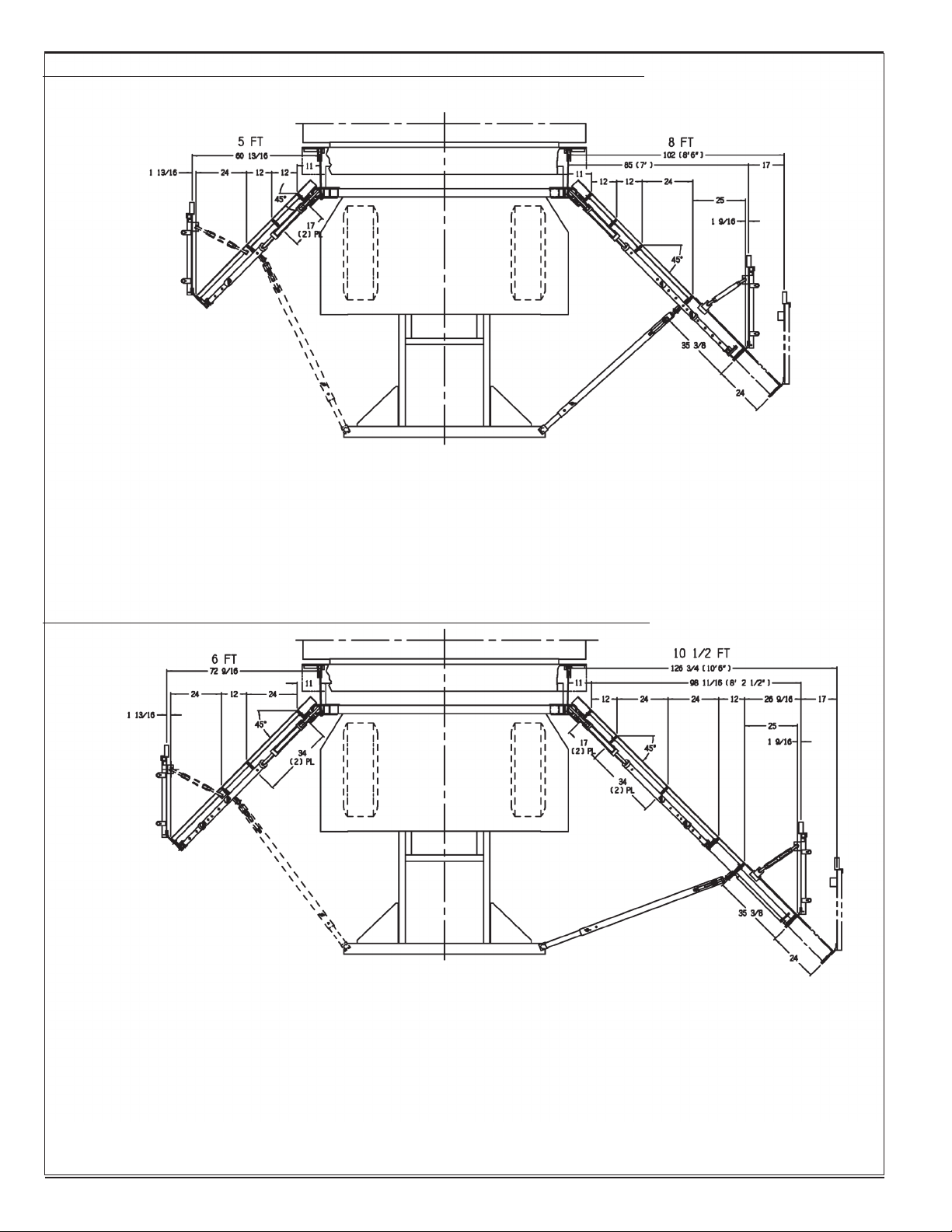
sp-8 BlAde ConfIGurAtIon WItH 2 ft HydrAulIC extensIon
SPD Left Side Discharge
SP-593 Rev-A blade & column assembly
(5 ft. fixed blade)
Consists of:
(1) SP-435 blade pivot
(2) SP-441 1 ft. blade section
(1) SP-444 2 ft. blade section
(1) SP-590 edger assembly
No push tube / turnbuckle
Paves 5 ft. at 45°
Right Side Discharge
SP-579 Rev-A, blade & column assembly
(5 ft. fixed blade)
Consists of:
(1) SP-435 blade pivot
(2) SP-441 1 ft. blade section
(1) SP-444 2 ft. blade section
(1) SP-590 edger assembly
With optional SP-751,
2 ft. hydraulic extension assembly
Paves 8’6” at 45°
sp-10 BlAde ConfIGurAtIon WItH 2 ft HydrAulIC extensIon
SPD Left Side Discharge
SP-588 Rev-A blade & column assembly
(6 ft. fixed blade)
Consists of:
(1) SP-435 blade pivot
(1) SP-441 1 ft. blade section
(2) SP-444 2 ft. blade section
(1) SP-590 edger assembly
No push tube / turnbuckle
Paves 6 ft. at 45°
Right Side Discharge
SP-420 Rev-B, blade & column assembly
(6 ft. fixed blade)
Consists of
(1) SP-435 blade pivot
(1) SP-441 1 ft. blade section
(2) SP-444 2 ft. blade section
(1) SP-590 edger assembly
With optional SP-752
(1) 2 ft. hydraulic extension assembly +
(1) SP-441 1 ft. blade section
Paves 10’6” at 45°
20
www.roadwidener.com
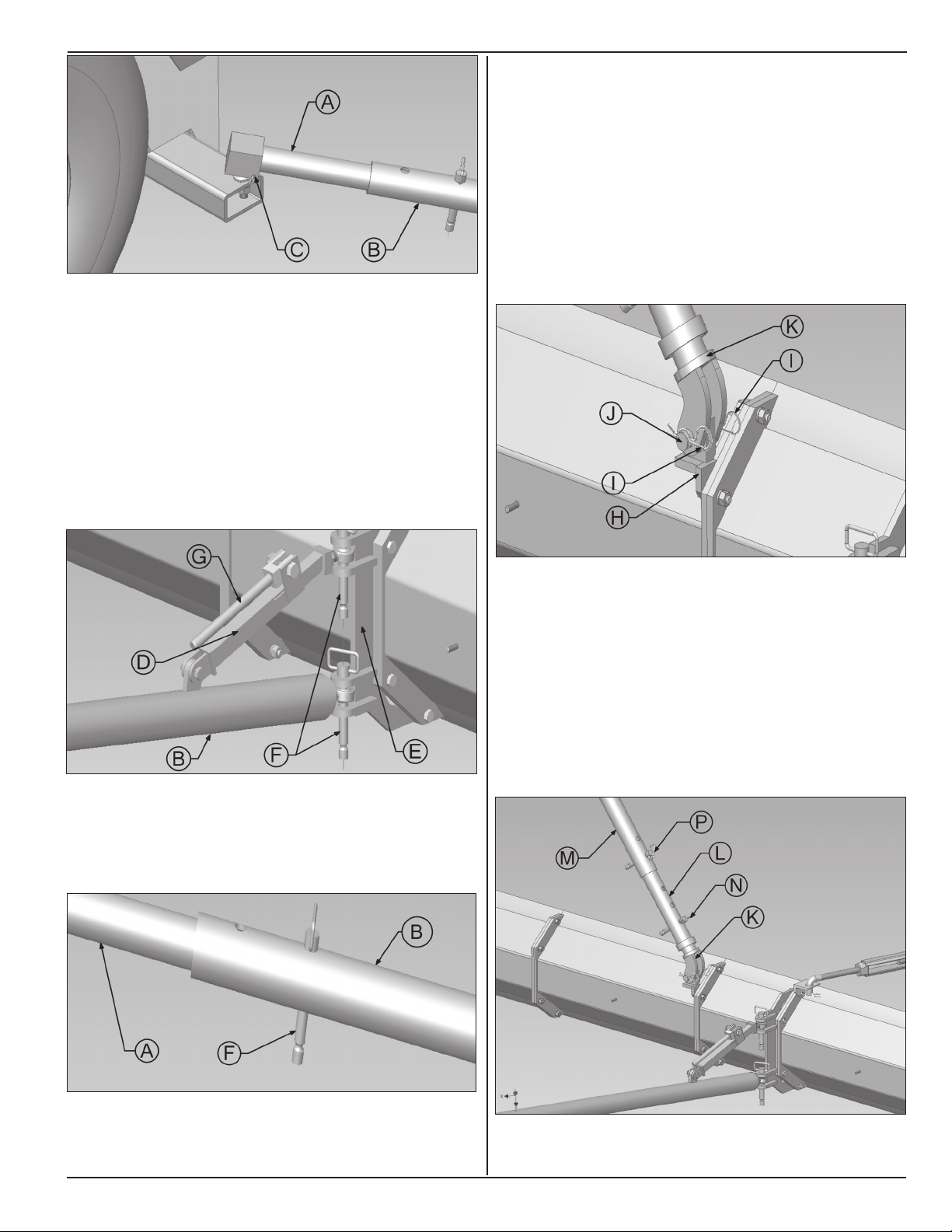
5. Insert inner push tube (A) into outer push tube (B).
6. Install push tube (A) over ball hitch on machine.
Install pins (C) to fasten push tube to ball hitch
7. On blade, align outer push tube (B) and stabilizer
(D) in mounting Bracket (E) holes and insert Hitch
pin (F).
Model SP-8 & 10
10. Slope mount (H) should be mounted at approximately
2/3rd of blade length. To change location of slope
mount (H), lower blade down to ground by toggling
grade & slope switches on operator console.
11. Pull out cotter pins (I) and remove hinge pin (J) to
remove end of the lower slope tube (K) from slope
mount (H).
12. Select blade section to install slope mount (H). Use
correct hardware.
8. Press reworked cam (G) to lock stabilizer.
9. Keeping blade angle as close as possible to 45
degrees, nd a conguration where one hole each
on inner push tube (A) and outer push tube (B) are
in-line and insert hitch pin (F) through them.
13. Remove pin (N) to release lower slope tube (K).
Bring lower end of slope tube (K) on to slope mount
(H). Reinsert hinge pin (J) through mounting holes
in lower slope tube (K) and slope mount (H). Install
cotter pins (I).
14. Adjust distance between in-line holes of lower (K),
middle (L) and top (M) slope tubes. Insert pins (N)
and (P) in in-line holes.
Note: Depending on material, a greater blade angle
may be needed to ll entire spread width. Narrow
spread widths do not require as much blade angle.
www.roadwidener.com
21
Model SP-8 &10
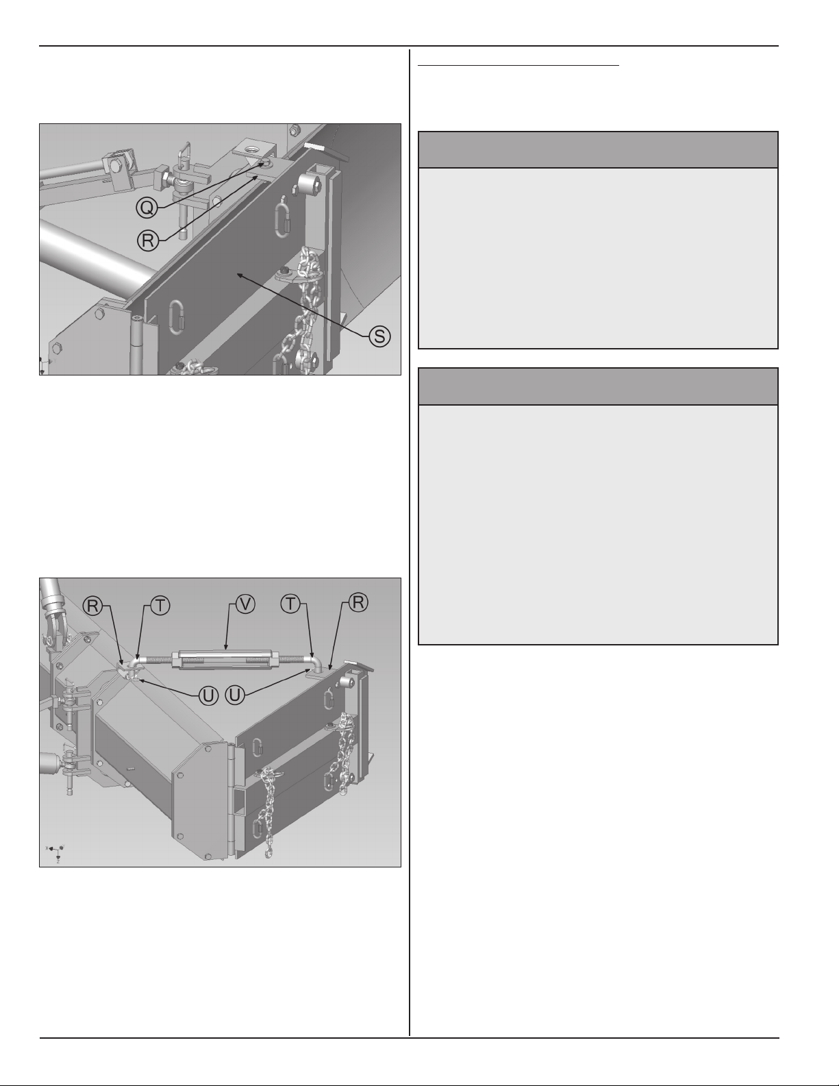
15. Remove locking hardware (Q) from turnbuckle
mount (R) on outer edger assembly (S). Swing
outer edger assembly (S) out.
5.3.2 CHAnGe BlAde lenGtH
Procedure illustrates blade on right side. On dual side
machines, procedure is the same for left side blade.
^ WARNING
Prevent serious injury or death.
Before performing inspections, service or
maintenance:
• Park machine on rm, level surface and
engage parking brake.
• Switch engine off.
• Close and lock control panel cover.
• Chock tires.
16. Retrieve outer edger brace from storage area.
Insert ends (T) of brace into turnbuckle mounts (R)
on outer edger and blade section.
17. Insert cotter pins (U) to secure outer edger brace.
18. Rotate turnbuckle (V) to adjust outer edger angle.
Outer edger should be parallel to blade assembly
inner edger.
^ WARNING
Prevent serious injury or death.
Blade components are heavy.
Use an adequate lifting device to raise, lift
and move blade and blade components.
Blade Pivot - 31 lbs.
1-Ft Blade Section - 57 lbs.
2 Ft Blade Section - 98 lbs.
Outer Edger Assembly - 113 lbs.
Hydraulic Extension Assembly - 225 lbs.
1. Start machine as in section 5.2. If machine is in
motion, park machine on a rm level surface,
engage parking brake by pushing E-stop button
fully down. Keep engine running at full rpm.
2. On dual side machine, toggle conveyor direction
switch to right side.
19. Toggle slope and grade switches on operator
console to adjust slope angle and grade of blade
for desired shoulder prole.
22
3. Lower blade to ground.
4. Switch engine off.
5. Close and lock control panel cover.
6. Remove pins (A) and remove push tube (B) from
blade.
www.roadwidener.com
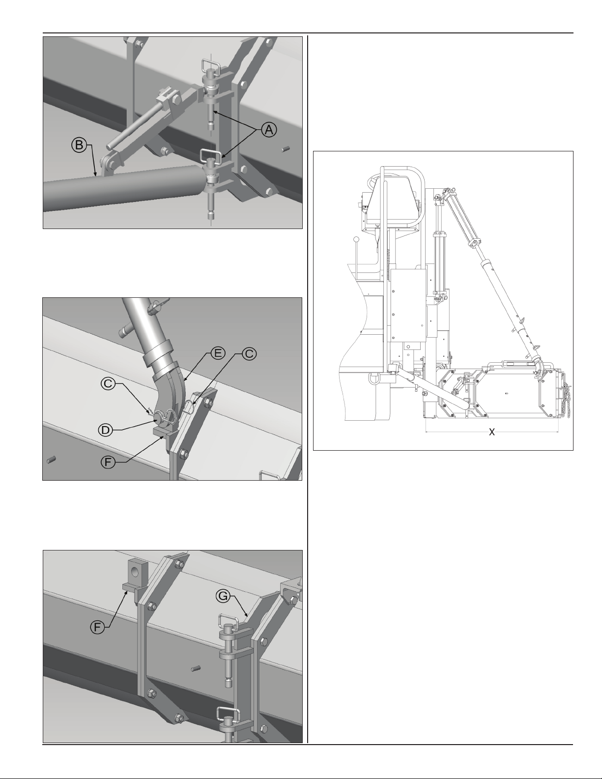
7. Pull out cotter pins (C) and remove hinge pin (D) to
disengage end of lower slope tube (E) from slope
mount (F).
Model SP-8 & 10
9. Set blade length to desired paving width by adding
or removing 1 foot and 2 foot sections. Blade
length should be such that desired paving width is
achieved when blade is set at approximately at 45°
angle to direction of travel.
Following illustration shows different combinations of
blade sections.
8. Unbolt Blade slope mount (F) and push tube
mounting bracket (G).
www.roadwidener.com
Dimension X: 4 Ft Blade
• (1) - Pivot Section
• (1) - 1 Ft Section
• (1) - 2 Ft Section
Dimension X: 7 Ft Blade
• (1) - Pivot Section
• (2) - 1 Ft Section
• (2) - 2 Ft Section
Hydraulic extension (option) can be used to hydraulically
increase overall blade length by up to 2 feet.
Note: Hydraulic extension must be mounted at farthest
end of blade. Moveable section of hydraulic extension
must always extend toward outer edger assembly.
Only outer edger assembly can be bolted to moveable
section of hydraulic extension.
23
Model SP-8 &10
Following illustration shows different combinations of
blade sections with hydraulic extension.
Dimension X: 7 - 8.5 Ft Blade
• (1) - Pivot Section
• (2) - 1 Ft Section
• (1) - 2 Ft Section
• (1) - 2 - 3.5 Ft* Hydraulic Extension
* Projected stroke length at 45° Paving Angle.
Dimension X: 4 - 5.5 Ft Blade
• (1) - Pivot Section
• (1) - 1 Ft Section
• (1) - 2 - 3.5 Ft* Hydraulic Extension
* Projected stroke length at 45° Paving Angle.
5.4 pusH roller setup
^ WARNING
Prevent serious injury or death.
Do not pull out push roller beyond 6th
hole.
Push roller assembly may fall out of tubes
and cause serious injury.
^ WARNING
Prevent serious injury or death.
Use caution while taking pivot pin out of
the push roller mount.
Push roller beam may fall out of push roller
mount and cause serious injury.
5.4.1 pIvot pIn loCAtIon
Pivot pin position for the push roller must be such that
push roller beam is symmetrically in middle between
end gates.
10. Reinstall blade push tube anchor (G) at
approximately ½ to ⅔ of blade length. Reinstall
blade slope mount (F) at approximately ⅔ of blade
length. Use suitable hardware.
11. Reinstall slope tubes, push tubes and set up paving
and slope angles as in section 5.3.1.
12. Start engine, check operation and check for leaks.
Paving width can also be varied by adjusting the push
tubes and changing the blade paving angle. While
changing the blade paving angle material ow must be
taken into consideration. Depending on material ow, a
greater blade angle may be needed to ll entire spread
width. Narrow spread widths do not require as much
blade angle.
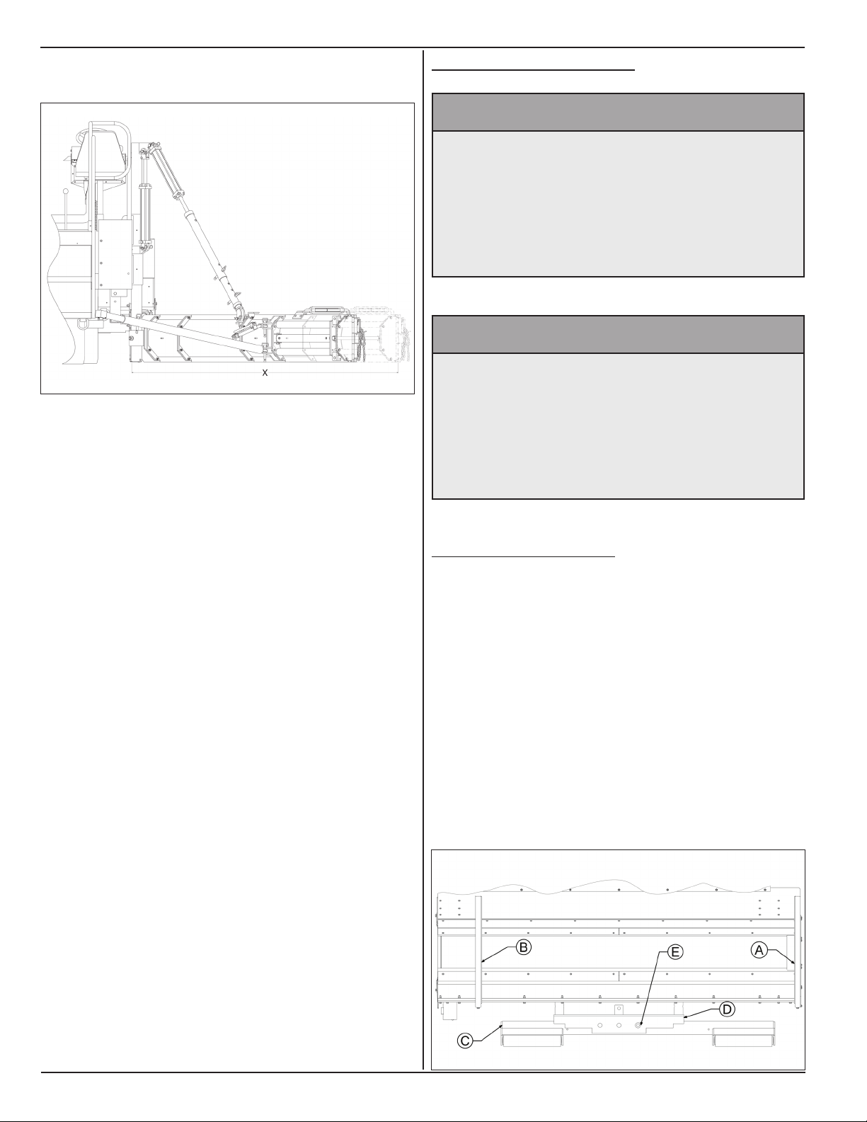
1. On a single sided machine, for right side paving,
location of left (A) and right (B) end gates are as
shown.
2. For this conguration, slide push roller beam (C)
towards left so pivot hole on push roller beam (C) is
in line with left hole on push roller mount (D).
3. Insert pivot pin (E) through in-line holes.
24
www.roadwidener.com
 Loading...