

Page 1
ProLine Series
PL2445 / PL2415
Operating Instructions
Page 2

Page 3

Table of Contents
I. FCC RF Exposure Compliance Requirements -
for Occupational Use Only...................... 1
II. About Topaz3............................................. 3
III. About Your Legacy ProLine Radios............... 4
IV. Unpacking and Checking Equipment............ 5
V. Radio Control Buttons / Operation Features.... 6
VI. Getting Started........................................... 7
Charging the NiMH Battery Pack.................. 7
Attaching and Removing the Battery Pack....... 9
Installing the Antenna................................ 10
Installing the Belt Clip................................ 10
Installing the Speaker Mic. Jack Cover........... 10
Attaching the Optional Speaker Mic.............. 11
VII. Radio Operation......................................... 12
Power On / Transmit................................. 12
VIII. Radio Functions......................................... 13
CTCSS Tone Signaling........................... 13
Scan Modes.......................................... 13
Normal Channel Scan............................ 13
Priority Channel Scan.............................. 14
Nuisance Delete...................................... 14
Busy Channel Lockout.............................. 15
Marked Idle............................................ 15
TX Delay................................................ 15
Time-Out-Timer (T-O-T)............................. 15
Time-Out-Timer Penalty (TX Inhibit).............. 15
Battery Save............................................ 16
Low Battery Warning................................. 16
Two-Tone Decode................................... 17
i
Page 4

Table of Contents, continued
IX. Compatible PL2445 / PL2415 Accessories.... 17
X. Licensing, Safety and Service Information.... 18
FCC Licensing........................................ 18
Safety Information................................... 18
Service................................................. 19
XI. Maintenance............................................ 19
XII. Software Copyrights.................................. 20
XIII. Topaz3 / Legacy Product Warranty.............. 21
ii
Page 5

Contenido
I. Requerimientos de Obediencia a la
Exposición de RF del FCC - para uso
Ocupacional Solamente ......................... 23
II. Acerca de Topaz3....................................... 25
III. Acerca de Legacy ProLine Radios.................. 26
IV. Desempaque y Verificación del Equipo......... 27
V. Botones de Control del Radio / Rasgos de
Funcionamiento...................................... 28
VI. Preparación................................................. 29
Cargador de la Batería de NiMH................... 29
Instalación y Retiro de la Batería................... 31
Instalación de la Antena............................. 32
Instalación del Clip de Cinturón................... 32
Instalación de la Cubierta de la Clavija de
Conexión de Micrófono de Altavoz............. 33
Agregando el Micrófono de Altavoz Opcional..33
VII. Operación del Radio.................................... 33
Encienda / Transmite................................. 33
VIII. Funciones del Radio.................................... 35
Señalización de Tono CTCSS.................. 35
Modos de Busqúeda............................... 35
Busqueda Normal de Canales..................... 35
Busqueda de Canal Prioritario.................... 36
Supresión de un Canal............................... 37
Bloqueo de Canal Ocupado........................ 37
Reposo Marcado...................................... 37
Espera TX (Transmisión).............................. 37
Expiracion de Tiempo del Temporizador
(T-O-T).................................................. 38
iii
Page 6

Contenido, continuado
VIII. Funciones del Radio, continuado
Penalidad por Tiempo Expirado
(Inhibicion de TX).......................................... 38
Preservación de Batería................................... 39
Aviso de Batería Baja...................................... 39
Descodificación de Dos Tonos...................... 39
IX. Accesorios Compatibles PL2445/PL2415........ 40
X. Información de Autorización, Seguridad y
Servicio................................................... 41
Licencia de la FCC.................................... 41
Información de Seguridad........................... 41
Servicio.................................................. 42
XI. Mantenimiento........................................... 42
XII. Derechos de Propiedad Literaria
del Software........................................... 43
XIII. Garantía del Producto de Topaz3 / Legacy...... 44
iv
Page 7

I. FCC RF Exposure Compliance Requirements
for Occupational Use Only
The Federal Communications Commission (FCC), with
its action in General Docket 93-62, November 7, 1997,
has adopted a safety standard for human exposure to
Radio Frequency (RF) electromagnetic energy emitted
by FCC regulated equipment. Topaz3 / Legacy subscribes
to the same safety standard for the use of its products.
Proper operation of this radio will result in user
exposure far below the Occupational Safety and Health
Act (OSHA) and Federal Communications Commission
limits.
CAUTION - DO NOT transmit for more than 50% of total
radio use time (50% duty cycle). Transmitting
more than 50% of the time can cause FCC
RF exposure compliance requirements to be
exceeded.
• This radio is NOT approved for use by the general
population in an uncontrolled environment. This radio
is restricted to occupational use, work related operations
only where radio operator must have the knowledge to
control the users exposure conditions for satisfying the
higher exposure limit allowed for occupational use.
• When transmitting, hold the radio in a vertical position
with its microphone 2 inches (5 cm) away from your
mouth.
• This device has been approved for use, at a maximum
duty factor of 50%, using the specific belt clip and
leather belt-holster tested for body-worn SAR compliance. Other belt clips or body-worn accessories may
1
Page 8

I. FCC RF Exposure Compliance Requirements
for Occupational Use Only, continued
not comply and should be avoided. ALWAYS use
Maxon, Legacy and TruTalk authorized accessories:
antennas, batteries, belt clips, speaker mics, etc.
• The radio is transmitting when the red LED on the
front of the radio is illuminated. You can cause the radio
to transmit by pressing the P-T-T bar on the radio.
• These are required operating configurations for meeting
FCC RF exposure compliance. Failure to observe these
restrictions mean violation.
2
Page 9

II. About Topaz3
Topaz3 is the exclusive supplier of Maxon®, Legacy
and TruTalk brand communication products.
Our product line ranges from FCC licensed two-way
radios suitable for Business and Industry (B&I) markets
like farm, government, law enforcement, utility, etc. to
consumer communications equipment for recreational
and light-duty business markets.
Product offerings include a variety of UHF and VHF
handheld and mobile radios, repeaters and RF link
modules as well as FRS (Family Radio Service), GMRS
(General Mobile Radio Service) radios, MURS (Multi
User Radio Service) radios, Citizens Band radios and
weather monitors.
Available accessory items include a variety of carrying
cases, spare batteries, desktop and mobile chargers,
ear bud speaker microphones and more for each radio
model.
For additional information on our product line, visit our
website: www.topaz3.com
3
Page 10

III. About Your Legacy ProLine Radios
The Legacy ProLine models PL2415 (VHF) and PL2445
(UHF) are fully programmable, synthesized radios featuring:
4 Channels of operation
2 Watts output power
Channel scan
38 Standard and 11 non-standard CTCSS tones
104 DCS Codes
Approved to MIL-STD810F Specifications
Scan channel delete
Busy channel lockout
Programmable CTCSS / DCS tones, wide/narrow channel
spacing, and two-tone decode
TX Inhibit
Die-cast aluminum frame, polycarbonate cabinet
Locking single-pin accessory connector
Battery save circuitry
Tri-color status LED
Spring steel belt clip
To assure satisfaction from the radio, we urge you to
thoroughly read the operation and function information
in this manual before operating your ProLine Series radio.
Application of some of the functions described in these
Operating Instructions are determined by the system you
use. Your radio communications Dealer will program the
radio so that you have the greatest number of functions
possible relative to your needs. Should you have questions
regarding the operation of the radio, please consult with
your radio communications Dealer, or contact the Topaz3
Customer Service Department: 1-800-821-7848, Ext. 499.
4
Page 11
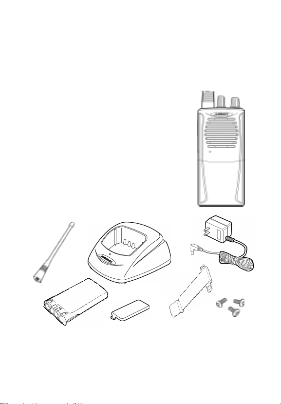
IV. Unpacking and Checking Equipment
Carefully unpack the radio and its accessories. Use the
item list below to identify the components included
in the product packaging, to ensure that no items are
discarded in the packing materials.
Radio Body
Antenna
Battery Charger (with plastic spacer
stored in charger base)
AC Adapter
NiMH Battery Pack
Speaker Microphone Jack Cover
Belt Clip
Screw Set
Operating Instructions
If any items are missing or damaged, you should
contact the Topaz3 Customer Service Department
for assistance: 1-800-821-7848, Ext. 499.
5
Page 12
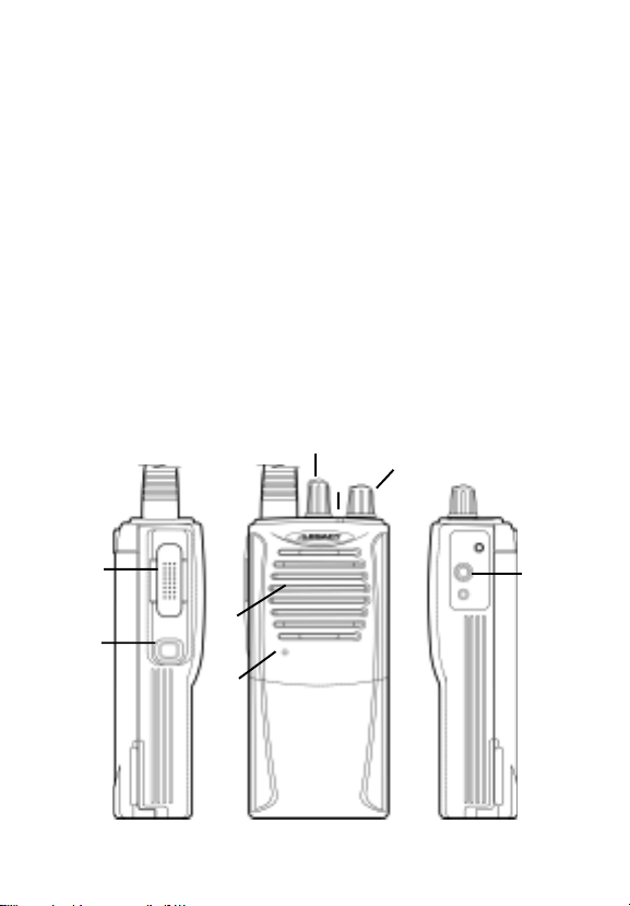
V. Radio Control Buttons / Operation Features
A) Push-To-Talk (P-T-T) button (left side of radio) Press and
hold while speaking into the radio microphone, release to
listen to incoming messages
B) Monitor button (left side of radio) Press and hold to turn
radio squelch off. Release to turn squelch back on.
C) Microphone (front of radio)
D) Speaker (front of radio)
E) Channel selector knob (top panel of radio)
F) LED Indicator (top panel of radio) Identifies transmit
(red), receive (signal only) orange, (signal + TONE) green,
setup mode (orange), battery low (flashing red)
G) Power / volume control (top panel of radio) Powers radio
on and adjusts radio volume
H) Speaker microphone jack (right side of radio)
E
G
F
A
H
D
B
C
6
Page 13

VI. Getting Started
Charging the NiMH Battery Pack
You will need to charge the battery pack fully before
initial use. For best results from your charging cycle,
follow these tips:
Ensure the ambient temperature is between 41 and
104° F (5 and 40° C) while charging. Temperatures
outside this range may not fully charge the battery.
Always switch OFF the transceiver equipped with
a NiMH battery pack before charging. Using the
radio during the charging cycle will hinder correct
charging.
Do not recharge the battery pack if it is already
fully charged. Doing so may cause the life of the
battery pack to shorten or the battery pack may
be damaged.
If the battery is stored for 2 months or more, it is a
good idea to complete the charge / discharge cycle
two or three times to allow the battery capacity
to return to normal.
Never dispose of the battery in fire - it can explode
causing personal injury.
Never attempt to disassemble the battery or remove
its case material or charging contacts. Do not short
the battery terminals.
7
Page 14

VI. Getting Started, continued
Charging the NiMH Battery Pack, continued
NOTE: The first few uses from the battery will not
be at normal capacity. After repeating the charge /
discharge cycle two or three times, the battery capacity
will increase to provide full capacity.
1. Plug the AC adapter cable in the adapter jack
located on the rear of the charger, then into
an AC outlet.
2. Slide the NiMH battery pack (or the radio equipped
with a NiMH battery pack) into the charging slot.
3. Ensure that the metal contacts on the battery pack
come in contact with the charging terminals.
4. When charging the NiMH battery pack alone, insert
the provided plastic spacer (stored in charger base)
into the charging well, then insert the battery pack.
5. The charger LED will light to advise that charging
has begun. Charge the standard battery pack for
9 hours. THEN REMOVE THE PACK OR RADIO
FROM THE CHARGER.
IMPORTANT NOTE: The charger DOES NOT
TURN OFF AUTOMATICALLY after the charging
cycle has been completed. Damage to the battery
or reduced battery life may result if charged in
excess of the recommended charging time.
8
Page 15

VI. Getting Started, continued
Attaching and Removing the Battery Pack
NOTE: After recharging the battery pack, REMOVE IT
FROM THE CHARGER. Charging the battery pack for
more than 5 days may reduce the battery life.
The battery pack life is over when its operating time
decreases even though it is fully and correctly charged.
Replace the pack with the manufacturers recommended model.
Average battery pack life from the supplied 750 mAh
battery is 11+ hours; the optional 1350 mAh battery,
19+ hours. This service time is calculated using 90%
standby, 5% transmit and 5% receive time.
After charging the battery pack as described, you are
ready to install it to the radio body. Simply;
1. Match the four grooves of the battery pack with the
guides on the back of the radio.
2. Slide the battery pack up along the back of the radio
until the release latch locks.
To remove the battery pack, push down on the release
latch and slide the pack downward, and away from the
radio.
9
Page 16

VI. Getting Started, continued
Installing the Antenna
Screw the antenna into the connector on the top of the
radio by holding the antenna at its base and turning
it clockwise until seated. Do not overtighten.
The antenna should never be used to carry your radio, or
as a base to clip radio accessories. Misuse of the antenna
can cause damage, and reduce your radios performance.
Installing the Belt Clip
We recommend that the belt clip is installed on the
radio. It keeps the radio from coming in contact with
hot surfaces, and away from your body if heat build-up
occurs with excess transmissions.
Use the two supplied screws to install the belt clip. If
a replacement is needed, use a screw designed to the
exact specifications as the original, to prevent accidental contact with internal circuitry, or possible personal
injury. Never use glue in conjunction with the provided
screws. Some of the glues components may crack the
radio back panel, causing radio damage and possible
personal injury.
Installing the Speaker Microphone Jack Cover
If you are not using an accessory, install the provided
cover over the speaker microphone jack using the screw
supplied. This will keep the radio water resistant.
10
Page 17

VI. Getting Started, continued
Attaching the Optional Speaker Microphone
1. Insert the speaker microphone jack into the radio.
2. Use the thumbscrew attachment on the speaker
microphone to make connection to the radio.
NOTE: The radio is not fully water resistant while the
speaker microphone is attached.
11
Page 18

VII. Radio Operation
Power On / Transmit
Power on the radio by turning the power / volume
control clockwise out of detent. You will hear a
confirmation tone on power-up. To check the radio
volume, press and hold the monitor button then rotate
the control to desired volume level.
Rotate the channel selector knob to choose the desired
channel. Press the monitor button to check the channel
for activity. To avoid interrupting another user, make
sure the channel is clear before you begin transmitting.
To transmit, place the radio microphone approximately
2 (5 cm) from your mouth. Press and hold the P-T-T
bar while speaking in a normal tone. Release the P-T-T
bar when you are finished speaking; the radio will be
placed into receive mode.
When the battery pack voltage becomes too low for
operation to continue, the LED will blink red and a
tone will sound. The radio will allow only one more
transmission - change or charge your battery. Refer to
the Low Battery Warning section of this manual.
12
Page 19

VIII. Radio Functions
CTCSS Tone Signaling
To help block out unwanted calls to your radio, the
PL2445 and PL2415 can be programmed by your radio
communications Dealer to scan for tones.
Scan Modes
Scanning is a Dealer programmable feature that allows
you to monitor a number of channels or channels within
a Group. Your radio communications Dealer will help
you define a scanning mode and your channel "scan list".
Normal Channel Scan
Once the scan list has been established, initiate
scan by pressing and holding the monitor button
and rotating the channel selector knob to the scan
enable channel. The LED will blink green to confirm
radio scanning.
If a conversation is detected on any of the channels
in the scan list, the radio will stop on that channel
and you will be able to hear the conversation. In
normal scan, you will be able to transmit on that
activechannel during the programmable scan delay
time. (The scan delay time is the amount of time
the radio will stay on that channel once activity
has ceased. Dealer programmable, 4 - 7 seconds
is typical).
13
Page 20

VIII. Radio Functions, continued
Normal Channel Scan, continued
The radio will resume scanning once the scan delay
time has expired, and will continue to scan until
the channel is changed. The LED will flash green.
In scan mode, if radio power is turned off and on,
the radio will return to the scan mode until a channel
is changed.
Priority Channel Scan
A single channel may be programmed as the
"Priority" channel. The radio will constantly monitor
this channel while scanning and when stopped on an
active channel. If a call is detected on the priority
channel, the radio will automatically move to, and
remain on, the priority channel. Priority channel
activity takes precedence over all other conversations.
Nuisance Delete
During receiving a signal or scan delay time, if the
monitor button is pressed, the current receiving channel
is deleted in scan list and is no longer scanned. When
the power is turned off and on, the deleted channel
is restored to the scan list.
14
Page 21

VIII. Radio Functions, continued
Busy Channel Lockout
When the RX signal is being received, the radios
transmitter is disabled. Dealer programming makes
this feature active or disabled.
Marked Idle
When used in conjunction with busy channel lockout,
the transmitter is allowed to operate as long as valid
RX tone is received. Dealer programming makes this
feature active or disabled.
TX Delay
The TX will remain active for approximately 180
seconds even though P-T-T button is released when
using CTCSS tones. This eliminates squelch tail by
sending CTCSS turn-off code (No Tone TX).
Time-Out-Timer (TOT)
The purpose of the time-out-timer is to prevent any
single person from using a channel for an extended
period. The time-out-time can be programmed from
10 seconds to 990 seconds by your radio Dealer.
Time-Out-Timer Penalty (TX Inhibit)
When TOT is applied, transmission will be inhibited
after time-out-time time expires. This TX inhibit time
can be selected and programmed by your Dealer from
15
Page 22

VIII. Radio Functions, continued
Time-Out-Timer Penalty (TX Inhibit), continued
1 second to 100 seconds. For instance, when TOT is
set to 3 minutes and TOT penalty is set to 5 seconds,
if you continuously transmit for 3 minutes, the radio
will stop transmitting. A tone will sound with each
P-T-T bar press until the 5-sec. TX inhibit time expires.
Press the P-T-T bar after the TX inhibit time expires
to resume transmitting.
Battery Save
The battery save function decreases the amount of
power used when a signal is not being received and
no operations are being performed (no bars are
being pressed, no controls are being used, etc.)
When the channel is not busy and no operation is
performed, battery save is enabled. When an operation
is performed, or a signal is received, battery save is
disabled.
Low Battery Warning
When the battery power goes below a pre-determined
value, the LED will blink red and a tone sounds. The
radio will then allow only one more transmission. After
that, the transceiver will stop transmitting. Replace
or recharge the battery pack.
16
Page 23

VIII. Radio Functions, continued
Two-Tone Decode
Each channel can be programmed with two-tone
decode by your radio communications Dealer.
Two-tone selections are: Individual Call, Group Call
and Super Group Call.
IX. Compatible PL2445 / PL2415 Accessories
750 mAh NiMH Battery pack (ACC-201)
1350 mAh NiMH Battery pack (ACC-202)
VHF Antenna, 6, 148-174 MHz (ACC-115)
UHF Antenna, 6, 450-490 MHz (ACC-145)
Single unit desktop slow charger (ACC-410)
Single unit desktop fast charger (ACC-412)
6-Station gang charger with ACC-410 chargers (ACC-441)
6-Station gang charger with ACC-412 chargers (ACC-442)
Ultra-lite headset w/ locking connector (ACC-616)
Ear bud speaker with in-line P-T-T, microphone and
locking connector (ACC-706)
Lapel speaker microphone with ear jack and locking
connector (ACC-726)
Heavy Duty speaker microphone with audio earphone
jack (ACC-727)
Coil-cord earphone, used with ACC-727 (QPA-1424)
Ear speaker, for use with ACC-726 (WTA-9F)
Leather case (ACC-302)
Nylon case (ACC-303)
2-pin to 1-pin Accessory adaptor (ACC-506)
17
Page 24

X. Licensing, Safety and Service Information
FCC Licensing
The Federal Communications Commission requires
the operator of this radio be properly licensed under
the applicable Part and / or Parts of the FCC Rules
and Regulations.
Consult with an authorized Topaz3 / Legacy radio
communications Dealer, or contact the nearest FCC
Field Office for information about obtaining a license.
Safety Information
WARNING - DO NOT hold the radio in such a manner
that the antenna is next to, or touching,
exposed parts of the body, especially the
face or eyes, while transmitting.
WARNING - DO NOT allow children to operate trans-
mitter-equipped radio equipment.
CAUTION - DO NOT operate the radio near unshielded
electrical blasting caps or in an explosive
atmosphere, unless it is a type especially
designed and qualified for such use.
CAUTION - DO NOT press and hold the transmit bar
(P-T-T) when not actually wishing to
transmit.
18
Page 25

X. Licensing, Safety and Service Information,
continued
Service
DO NOT tamper with internal radio adjustments damage to the equipment and / or improper operation
may result. There are no serviceable items inside the
radio. It is recommended that you return the radio to
a qualified Topaz3 / Legacy radio communications
Dealer for any service or repairs.
XI. Maintenance
Your Legacy radio is designed to be maintenance-free,
and can be kept in good working condition by:
• Cleaning all external surfaces with a clean cloth,
dampened in a mild solution of dishwasher and
detergent diluted in water. Apply the solution
sparingly to avoid any moisture leaking into cracks
crevices - NEVER submerge the radio. Use a
non-metallic brush if needed to dislodge stubborn
particles. Dry the radio surface thoroughly with a
soft, lint-free cloth.
• DO NOT use solvents or spirits for cleaning - they
may permanently damage the radio.
• Clean the battery and accessory jack contacts with
a lint-free cloth to remove dirt, grease or foreign
materials.
19
Page 26

XII. Software Copyrights
The Topaz3 / Legacy products described in these
operating instructions may include copyrighted Topaz3
/ Legacy software programs stored in semi-conductor
memories or other media. Laws in the United States
and other countries preserve for Topaz3 / Legacy
certain exclusive rights for copyrighted software
programs, including the exclusive right to copy or
reproduce in any form the copyrighted software
program.
Accordingly, the copyrighted Topaz3 / Legacy software programs contained in the Topaz3 / Legacy
product(s) described in this operating instruction
manual may not be copied or reproduced without
the express written permission of Topaz3, LLC.
Furthermore, the purchase of Topaz3 / Legacy products
shall not be deemed to grant either directly or by
implication, estoppel, or otherwise, any license
under the copyrights, patents or patent applications
of Topaz3, LLC, except for normal non-exclusive,
royalty-free license to use that arises by operation
of law in the sale of a product.
20
Page 27

XIII. Topaz3 / Legacy Product Warranty
Topaz3, LLC (hereinafter, “Topaz3”) warrants that the Products and
included accessories sold herein will be free from defects in workmanship
or materials under normal use and service for a period of two (2) years
(one year for accessories) from the date of purchase by the original end
user, provided that the buyer has complied with the requirements stated
herein. This warranty is offered to the initial end user and is not assignable
or transferable. Topaz3 is not responsible for any ancillary equipment
which is attached to or used in conjunction with Topaz3 / Legacy products.
If the Product fails to function under normal use because of manufacturing
defect(s) or workmanship during the two (2) years period following the
date of purchase, it will be replaced or repaired at Topaz3's option at no
charge when returned to the place of purchase. The defective unit must be
accompanied by proof of the date of purchase in the form of a sales receipt.
The sole obligation of Topaz3 hereunder shall be to replace or repair the
Product covered in this Warranty. Replacement, at Topaz3's option, may
include a similar or higher-featured product. Repair may include the
replacement of parts or boards with functionally equivalent reconditioned
or new parts or boards. Replaced parts, accessories, batteries, or boards
are warranted for the balance of the original time period. All replaced parts,
accessories, batteries or boards become the property of Topaz3.
Topaz3 shall have no obligation to make repairs or to cause replacement
required through normal wear and tear or necessitated in whole or in part
by catastrophe, fault or negligence of the user, improper or unauthorized
alterations or repairs to the Product, use of the Product in a manner for
which it was not designed, or by causes external to the Product. This
warranty is void if the serial number is altered, defaced or removed.
The user is responsible for the payment of any charges or expenses
incurred for the removal of the defective product from the vehicle or site
of its use, for the transportation of the product to the place of repair, for
the return of the repaired / replaced product to the site of its use and for
the reinstallation of the product.
21
Continued.
Page 28

XIII. Topaz3 / Legacy Product Warranty,
continued
THE EXPRESS WARRANTIES CONTAINED HEREIN ARE IN LIEU OF
ALL OTHER WARRANTIES, EITHER EXPRESSED OR IMPLIED OR
STATUTORY, INCLUDING, WITHOUT LIMITATION, ANY WARRANTY
OF MERCHANTABILITY OR FITNESS FOR A PARTICULAR
PURPOSE.
FOR ANY PRODUCT WHICH DOES NOT COMPLY WITH THE
WARRANTY SPECIFIED, THE SOLE REMEDY WILL BE REPAIR OR
REPLACEMENT. IN NO EVENT WILL TOPAZ3 BE LIABLE TO THE
BUYER OR ITS CUSTOMERS FOR ANY DAMAGES, INCLUDING
ANY SPECIAL, INCIDENTAL, INDIRECT OR CONSEQUENTIAL
DAMAGES, OR FOR THE LOSS OF PROFIT, REVENUE OR DATA
ARISING OUT OF THE USE OF OR THE INABILITY TO USE THE
PRODUCT.
This warranty is void for sales and deliveries outside of the U. S. A.
22
Page 29

Contenido
I. Requerimientos de Obediencia a la
Exposición de RF del FCC - para uso
Ocupacional Solamente ......................... 23
II. Acerca de Topaz3....................................... 25
III. Acerca de Legacy ProLine Radios.................. 26
IV. Desempaque y Verificación del Equipo......... 27
V. Botones de Control del Radio / Rasgos de
Funcionamiento...................................... 28
VI. Preparación................................................. 29
Cargador de la Batería de NiMH................... 29
Instalación y Retiro de la Batería................... 31
Instalación de la Antena............................. 32
Instalación del Clip de Cinturón................... 32
Instalación de la Cubierta de la Clavija de
Conexión de Micrófono de Altavoz............. 33
Agregando el Micrófono de Altavoz Opcional..33
VII. Operación del Radio....................................33
Encienda / Transmite................................. 33
VIII. Funciones del Radio.................................... 35
Señalización de Tono CTCSS.................. 35
Modos de Busqúeda............................... 35
Busqueda Normal de Canales..................... 35
Busqueda de Canal Prioritario.................... 36
Supresión de un Canal............................... 37
Bloqueo de Canal Ocupado........................ 37
Reposo Marcado...................................... 37
Espera TX (Transmisión).............................. 37
Expiracion de Tiempo del Temporizador
(T-O-T).................................................. 38
Page 30

Contenido, continuado
VIII. Funciones del Radio, continuado
Penalidad por Tiempo Expirado
(Inhibicion de TX).......................................... 38
Preservación de Batería................................... 39
Aviso de Batería Baja...................................... 39
Descodificación de Dos Tonos...................... 39
IX. Accesorios Compatibles PL2445/PL2415........ 40
X. Información de Autorización, Seguridad y
Servicio................................................... 41
Licencia de la FCC.................................... 41
Información de Seguridad........................... 41
Servicio.................................................. 42
XI. Mantenimiento........................................... 42
XII. Derechos de Propiedad Literaria
del Software........................................... 43
XIII. Garantía del Producto de Topaz3 / Legacy...... 44
Page 31

I. Requerimientos de Obediencia a la
Exposición de RF del FCC - para
uso Ocupacional Solamente
La Comisión Federal de Comunicaciones (FCC), con su
medida en Registro General 93-62, del 7 de noviembre
de 1997, ha adoptado una norma de seguridad para
la exposición humana a la energía electromagnética
de radiofrecuencia (RF) emitida por equipo regulado
por la FCC. Topaz3 / Legacy adopta la misma norma
de seguridad para el uso de sus productos. La operación
adecuada de este radio resultará en una exposición del
usuario muy inferior a los límites establecidos por el
Acta de Seguridad y Salud Ocupacional (OSHA) y la
Comisión Federal de Comunicaciones.
PRECAUCIÓN - No transmita por más de 50% del tiempo del
uso total del radio (ciclo de trabajar de 50%).
Transmitiendo más del 50% del tiempo puede
causar que los requisitos del RF del FCC de la
conformidad de la exposición sean excedido.
• El radio NO esta aprobado por uso por la población
general en un ambiente libre. Esta radio está restringido
al uso ocupacional, a las operaciones relacionadas al
trabajo solamente donde el operador de radio debe
tener el conocimiento para controlar las condiciones
de la exposición del usuario para satisfacer el l
alto de exposición permitido para el uso ocupacional.
• Cuando transmite, sostenga el radio en una posición
vertical con su micrófono 5 cm lejos de su boca.
ímite más
23
Page 32

I. Requerimientos de Obediencia a la
Exposición de RF del FCC - para
uso Ocupacional Solamente, continuado
• Este disposition se ha probado para usar como un factor
de función máxima del 50%, usando el eclip del cinturón
y estuche de cuero específico para usar en el cuerpo;
probado en conformidad con la organización SAR.
Otros clips del cinturón o accesorios para usar en el
cuerpo pueden no conformarse y deben ser evitados.
SIEMPRE hay que usar accesorios autorizados de marca
Maxon, Legacy y TruTalk, tal como antenas, baterías,
clip del cinturón, micrófonos del orador, etc.
• El radio transmite cuando el diodo luminoso se ilumina
rojo en el frente del radio. Presionando el conmutador
de P-T-T en del radio causa el radio a transmitir.
• Estas son configuraciones de funcionamiento requeridas
para la conformidad de la reunión de exposición de la
FCC RF. Incumplimiento de observar estas restricciones,
significa violación.
24
Page 33

II. Acerca de Topaz3
Topaz3 es el suplidor exclusivo de las marcas de productos
Maxon®, Legacy y TruTalk.
Nuestra línea de productos alcanza desde radios de dos
vías convenientes para mercados de Negocios e Industrias
(B & I) tales como granjas o fincas, gobierno, personal que
ejecuta la ley, servicio público, etc. a equipos para
comunicaciones del consumidor para uso de mercados
recreacionales y de negocios con funciones livianas.
Los productos incluyen una variedad de radios portátiles y
móbiles de UHF y VHF, repetidoras y módulos de RF Link,
tanto como Radios de Servicio Familiar (FRS), Servicio
General de Radios Móbiles (GMRS), Multi Servicio de Radio
del Utilizador (MURS), Radios de Banda Ciudadana y
monitores del tiempo.
Items de accesorios disponibles incluyen una variedad
de estuches para cargar los radios, baterías, cargadores de
escritorios y móbiles, micrófonos parlantes de oído y más
para cada modelo de radio.
Para información adicional de los productos de Topaz3,
visite nuestro website en www.topaz3.com
25
Page 34

III. Acerca de Legacy ProLine Radios
Los modelos de Legacy ProLine PL2445 (VHF) y PL2415
(UHF) son radios con funciones sintetizadas totalmente
programables y contiene los siguientes rasgos:
4 Canales de operación
2 Watts de poder de rendimiento
Búsqueda de canales
38 Tonos CTCSS estándard y 11 no estándard
104 Códigos DCS
Características técnicas aprobadas a MIL-STD810F
Búsqueda de anulación de canales
Función de canal ocupado
Programables Tonos CTCSS, DCS, espacio de canal
ancho / estrecho y dos tonos decodificador
Inhibe el transmisor
Marco de aluminio y polycarbonato
Conector adicional con cierre de 1 pin
Circuito de ahorro de batería
Pantalla tri-color
Clip del cinturón con spring de hierro
Para asegurar la satisfacción del radio, por favor, lea
cuidadosamente las instrucciones sobre las funciones
y operaciones explicados en este manual antes de usar
los radios de la Serie Proline.
Aplicación de algunas de las funciones descritas en este
Instrucciones Operativas son determinadas dependiendo
del sistema que usted use. Su Distribuidor programa el radio
para que de esta manera, usted pueda tener el mayor número
de funciones posibles de acuerdo a sus necesidades. Si usted
tiene preguntas relativas a la operación de este radio, por
favor, consulte a su Distribuidor de Radios autorizado o
consulte al departmento de Servicios al Cliente de Topaz3
al 1-816-891-6320, extensión 499.
26
Page 35

IV. Desempaque y Verificación del Equipo
Con cuidado, desempaque el radio y su accesorios.
Use la lista de artículos de abajo para identificar los
componentes incluídos en el paquete del producto
para asegurar que no se deseche ningún artículo en
los materiales del embalaje.
Radio
Antena
Cargador de la Batería (con
espaciador de plástico colocado
en la base del cargador)
Adaptador
Batería de NiMH
Micrófono de Altavoz con Cubierta
sobre Clavija de la Conexión
Clip del Cinturón
Set de Tornillos
Instrucciones Operativas
Si cualquiera de los artículos faltaron o se dañaron, por
favor de hacer reclamo al departmento de Servicios al
Cliente de Topaz3 al 1-816-891-6320, extensión 499
para ayuda.
27
Page 36

V. Botones del Control del Radio /
Rasgos de Funcionamiento
A) Botón de P-T-T (siglas en inglés de Presione Para Hablar),
situado al lado izquierdo del radio - Presione y sostenga
mientras que habla en el micrófono del radio, descargue
para escuchar los mensajes.
B) Botón de monitoreo, localizado al lado izquierdo del radio -
Presione y sostenga para apagar el silenciador del radio.
Descargue para encender el silenciador.
C) Micrófono, situado en el frente del radio.
D) Altavoz, situado en el frente del radio.
E) Perilla del selector de canal.
F) Indicador del diodo luminoso, situado en el panel superior
del radio - Identifica cuando el radio transmite (color rojo),
recibe (señal solamente) color naranja, (señal y CTCSS) color
verde, modo de la disposición (color naranja), el punto bajo
de la batería (color que centellea rojo).
G) Control de la potencia y volumen, situado en el panel
superior del radio - Enciende y ajusta el volumen del radio.
H) Conexión del micrófono del altavoz, situado al lado derecho
del radio.
E
G
F
A
B
D
H
C
28
Page 37

VI. Preparación
Cargador de Batería de NiMH
Necesitará cargar la batería totalmente antes de su uso
inicial. Para mejores resultados de su ciclo de carga,
siga estas puntas:
• Asegurar que la temperatura del ambiente es entre
41 y 104° F (5 y 40° C) mientras se está cargando.
Temperaturas fuera de este rango no dejan cargar
totalmente la batería.
• Siempre apague el transrecibidor equipado con una
batería de NiMH antes de cargar. Usando el radio
durante un ciclo de carga impedirá correcto
cargamiento.
• No recargue la batería si ya está totalmente cargada.
Puede acortar la vida útil o dañar la batería.
• Si se guarda la batería por 2 meses o más una idea
buena es completar dos o tres veces el ciclo de
carga y descarga para dejar que la capacidad
de la batería vuelva a normal.
• Nunca disponga de la batería en fuego - puede
explotar y causar lesión personal.
• Nunca intente desmontar la batería o quitar su
material del estuche o los contactos de carga.
29
Page 38

V. Preparación, continuado
Cargador de Batería de NiMH, continuado
NOTA: Los primeros pocos usos de la batería no estarán
a "normal" capacidad. Después de repetir dos o tres
veces el ciclo de cargar y descargar, la capacidad de la
batería se aumentará para proporcionar capacidad llena.
1. Enchufe el cable del adaptador de corriente AC en
su propia conexión localizada atrás del cargador,
y en un toma de corriente de AC.
2. Deslice la batería de NiMH (o la radio equipado con
la batería de NiMH) en la hendedura del cargador.
3. Asegura que los contactos de metal de la batería
hagan contacto con las terminales del cargador.
4. Cuando la batería de NiMH se esté cargando sola,
inserte el espaciador de plástico (colocado en la
base del cargador) y entonces inserte la batería.
5. Cuando comienza el ciclo de cargamiento, se
enciende una luz de LED en el cargador
significando que a comenzado a cargar. Carga la
batería normal por un total de 9 horas, ENTONCES
RETIRE EL RADIO O BATERIA DEL CARGADOR.
NOTA IMPORTANTE: El cargador no SE APAGA
AUTOMATICAMENTE después que el ciclo se ha
completado. Daño a la batería o reducción de la
duración de ésta puede ocurrir, si es cargada en
exceso del tiempo de carga recomendado.
30
Page 39

V. Preparación, continuado
Instalación y Retiro de la Batería
NOTA: Después de recargar la batería, removerla
del cargador.
La vida de la batería se acaba cuando su tiempo
de operación disminuye aunque está totalmente
y correctamente cargada. Reemplace la batería
con un modelo recomendado por el fabricante.
La media vida de la batería de 750 mAh son 11+
horas más o menos; la vida de la batería opcional
de 1350 mAh es más de 19+ horas. Este servicio se
calcula utilizando un 90% estado de espera, un 5%
de tiempo de transmitir y un 5% de tiempo de recibir.
Después de cargar la batería como se describió, está
lista para instalarla al cuerpo de la radio. Simplemente
haga lo siguiente;
1. Haga coincidir las cuatro ranuras de la batería con
las guías correspondientes en la parte posterior
del radio.
2. Deslice la batería arriba a lo largo de la parte
posterior del radio hasta que cierre el pestillo
del radio.
Para retirar la batería, empuje en el pestillo del
descargo y deslice la batería hacia afuera del radio.
31
Page 40

V. Preparacion, continuado
Instalación de la Antena
Enrosque la antena en el conector en la cima del radio
sujetando la antena a su base y dando vuelta a la
derecha hasta que quede firme. No apriete demasiado.
Nunca se debe usar la antena para llevar su radio, o
como una base para sujetar accesorios del radio. Mal
uso de la antena puede causar daño, y reduce el
rendimiento de su radio.
Instalación del Clip de Cinturón
Recomendamos que el clip de cinturón sea instalado
en el radio. El clip de cinturón guarda el radio de
entrar en contacto con superficies calientes y lejos de
su cuerpo si ocurre calor por exceso de transmisiones.
Use los dos tornillos suministrados para instalar el
clip de cinturón. Si se requiere un reemplazo, use un
tornillo diseñado con características técnicas exactas
como el original, para prevenir contacto accidental
con circuitería interior, o posible lesión personal.
Nunca use cola para pegar en relación con tornillos.
Algunos de los componentes de cola para pegar
crujirían el tablero del radio, causando daño al radio
y posible lesión personal.
32
Page 41

V. Preparacion, continuado
Instalación de la Cubierta de la Clavija de Conexión
de Micrófono de Altavoz
Si no usa un accesorio, instale la cubierta encima
de la clavija de conexión del micrófono de altavoz
usando el tornillo suministrado. Este mantedrá el
radio resistente al agua.
Agregando el Micrófono de Altavoz Opcional
1. Inserte la conexión del micrófono del altavoz
en la radio.
2. Utilice los tornillos de enlace en el micrófono
del altavoz para hacer la conexión a la radio.
NOTA: El radio no es completamente resistente al
agua; mientras que este conectado con el micrófono
del altavoz.
VII. Operación del Radio
Encienda / Transmite
Encienda el radio dando vuelta a la derecha al botón
de control de volumen. Oirá un tono de confirmación.
33
Page 42

VII. Operación del Radio, continuado
Encienda / Transmite, continuado
Chequear el volumen del radio,
presionando y manteniendo
el botón de monitoreo, entonces
gire el control más allá en el
sentido de las agujas.
Rote la perilla del selector de canal para elegir el
canal deseado. Presione el botón del monitor para
chequear la activadad del canal. Para evitar interrumpir
otro usuario, asegúrese de que el canal está limpio
antes de usted comenzar a transmitir.
Para transmitir, ponga el micrófono de la radio
aproximadamente 5 cm (2) de su boca entonces
presione y mantenga la conmutador de P-T-T (siglas
en inglés de Presione Para Hablar) mientras habla en
su voz normal. Cuando se termina de hablar; descarga
el conmutador de P-T-T y el radio se pondrá en modo
de recibe.
Si el voltaje de la batería se vuelve demasiado bajo
para continuar el funcionamiento, la transmisión se
detendrá y el diodo luminoso pestañeará rojo. Cambie
o cargue su batería para continuar el funcionamiento
del radio. Refiérase a la sección de Aviso de Batería
Baja en estas instrucciones.
34
Page 43

VIII. Funciones del Radio
Señalización de Tono CTCSS
Para ayudar a bloquear las llamadas indeseadas a su
radio, PL2445 y PL2415 pueden ser programados por
su distribuidor de equipos de radiocomunicaciones
para buscar tonos.
Modos de Búsqueda
La búsqueda es una función programable por su
distribuidor que le permite escuchar un número de
canales o canales dentro de un grupo. Su distribuidor
le ayudará a definir un modo de búsqueda y la «scan
list» (lista de búsqueda) de canales.
Búsqueda Normal de Canales
Una vez que se ha establecido la lista de
búsqueda, inicie la búsqueda oprimiendo y
manteniendo oprimido el botón monitor y
girando la perilla del selector de canales al
canal «scan enable» (habilitar búsqueda). La luz
indicadora LED (diodo emisor de luz) destellará
en verde para confirmar que el radio está en el
modo de búsqueda.
Si el radio detecta una conversación en cualquiera
de los canales de la lista de búsqueda, la sintonía
del radio se detendrá en ese canal y usted podrá
oír la conversación. En una búsqueda normal,
35
Page 44

VIII. Funciones del Radio, continuado
Búsqueda Normal de Canales, continuado
usted podrá transmitir en ese canal activo durante
el tiempo de espera programable de la búsqueda.
(El tiempo de espera de búsqueda es el período
de tiempo durante el cual el radio permanecerá
en ese canal, una vez que haya cesado la actividad.
Este período es programable por su distribuidor y
tiene un valor típico de 4 a 7 segundos).
El radio resumirá la búsqueda una vez que el
período de espera de búsqueda haya expirado y
continuará la búsqueda hasta que se cambie el
canal. La luz indicadora LED destellará en color
verde. En el modo de búsqueda, si se apaga el
radio y se vuelve a encender, el radio retornará al
modo de búsqueda hasta que se cambie un canal.
Búsqueda de Canal Prioritario
Un canal puede ser programado como canal
«prioritario». El radio observará constantemente
cualquier actividad en este canal mientras está
en el modo de búsqueda y cuando se detiene en
un canal activo. Si se detecta una llamada en el
canal prioritario, el radio pasará automáticamente
al canal prioritario y permanecerá en esa frecuencia
mientras dure la actividad. La actividad en el canal
prioritario tiene precedencia sobre todas las otras
conversaciones.
36
Page 45

VIII. Funciones del Radio, continuado
Supresión de un Canal
Durante la recepción de una señal o durante el período
de espera de búsqueda, si el botón monitor se oprime,
el canal que se esté sintonizando será suprimido en la
lista de búsqueda y no se volverá a sintonizar durante
la búsqueda. Cuando se apague y se encienda el radio,
el canal suprimido será incorporado nuevamente en la
lista de búsqueda.
Bloqueo de Canal Ocupado
Cuando la señal RX (Recepción) esté siendo recibida,
el transmisor de radio queda inhabilitado. La programación por el distribuidor de equipos de radio puede
hacer que esta función esté activa o inhabilitada.
Reposo Marcado
Cuando se usa en conjunto con el bloqueo de canal
ocupado, el transmisor podrá operar siempre que se
reciba un tono válido RX. La programación por el
distribuidor de equipos de radio puede hacer que
esta función esté activa o inhabilitada.
Espera TX (Transmisión)
La función TX permanecerá activa durante aproximadamente 180 segundos, aun cuando el botón P-T-T
(siglas en inglés de «Oprimir Para Hablar») se suelte
cuando se usen los tonos CTCSS. Esto elimina el ruido
causado por el circuito silenciador, enviando en la
37
Page 46

VIII. Funciones del Radio, continuado
Espera TX (Transmisión), continuado
señal el código CTCSS de apagado (No hay tono TX).
Expiración de Tiempo del Temporizador (T-O-T)
El objeto de enviar la señal de expiración de tiempo
del temporizador es evitar que cualquier persona pueda
usar un canal durante un largo período de tiempo. El
tiempo del temporizador puede ser programado desde
10 segundos hasta 990 segundos por su distribuidor de
equipos de radio.
Penalidad por Tiempo Expirado (Inhibición de TX)
Cuando se aplica la función T-O-T, la transmisión será
terminada después que expire el tiempo programado
en el temporizador. Este tiempo de inhibición de
transmisión se puede seleccionar y programar por su
distribuidor desde 1 segundo hasta 100 segundos. Por
ejemplo, cuando el T-O-T está ajustado en 3 minutos y
la penalidad de T-O-T en 5 segundos, si usted transmite
continuamente durante 3 minutos el radio dejará de
transmitir. Cada vez que oprima el botón P-T-T para
tratar de transmitir, sonará un tono hasta que el tiempo
de inhibición de transmisión de 5 segundos haya
transcurrido.
Pulse el botón P-T-T después de que haya transcurrido
el tiempo de inhibición de transmisión
para que pueda volver a transmitir.
38
Page 47

VIII. Funciones del Radio, continuado
Preservación de Batería
La función de reducción del consumo de batería
reduce la cantidad de energía usada por el radio
cuando no se recibe una señal y no se efectúa ninguna
otra operación (no se oprime ninguna barra o botón,
no se usa ningún control, etc.).
Cuando el canal no está ocupado y no se efectúa
ninguna operación, se habilitará la función de
reducción de consumo de batería. Cuando se efectúe
una operación con el radio o se reciba una señal,
se inhabilitará esta función.
Aviso de Batería Baja
Cuando la energía de la batería baje por debajo de un
valor predeterminado, la luz LED destellará en color
rojo y sonará un tono. El radio permitirá solamente una
transmisión adicional. Después de eso, el transceptor
dejará de transmitir. Cambie o recargue el paquete de
baterías.
Descodificación de Dos Tonos
Cada canal puede ser programado con una descodificación de dos tonos por su distribuidor de equipos
de radio. Las selecciones de dos tonos son:
Llamada Individual, Llamada de Grupo y Llamada
de SuperGrupo.
39
Page 48

IX. Accesorios Compatibles PL2445/PL2415
Paquete de Batería de 750 mAh NiMH (ACC-201)
Paquete de Batería de 1350 mAh NiMH (ACC-202)
Antena VHF, 6, 148-174 MHz (ACC-115)
Antena UHF, 6, 450-490 MHz (ACC-145)
Sola unidad Cargador lento de escritorio (ACC-410)
Sola unidad Cargador rapido de escritorio (ACC-412)
Grupo de Cargadores de 6 estaciones,
con cargador ACC-410 (ACC-441);
con cargador ACC-412 (ACC-442)
Receptor de cabeza de Ultra-lite con conector el
bloquer (ACC-616)
Micrófono Parlante de Oído con conector el bloquer
(ACC-706)
Micrófono Parlante del altavoz de la solapa con
conector el bloquer (ACC-726)
Micrófono Parlante resistente con enchufe de auricular
(ACC-727)
Audífono con cordon usado con ACC-727 (QPA-1424)
Parlante de Oído para el uso con ACC-726 (WTA-9F)
Estuche de Cuero (ACC-302)
Caso de Nylon (ACC-303)
Adaptador de 2-pin to 1-pin (ACC-506)
40
Page 49

X. Información de Autorización, Seguridad
y Servicio
Licencia de la FCC
La Comisión Federal de Comunicaciones requiere que
el operador de este radio tenga la licencia pertinente
conforme a la/s Parte/s de las Normas y
Reglamentaciones de la FCC correspondientes.
Consulte con su Distribuidor de Topaz3 / Legacy, o
con la oficina regional más cerca de la FCC para
recibir información sobre cómo obtener una licencia.
Información de Seguridad
ADVERTENCIA - NO sostenga el radio de manera tal que la
antena esté junto a, o toque, partes
expuestas del cuerpo, especialmente la cara
o los ojos, mientras transmite.
ADVERTENCIA - NO permita que los niños operen este
equipo de radio equipado con transmisor.
PRECAUCIÓN - NO opere el radio cerca de cápsulas
eléctricas no protegidas o en una atmósfera
explosiva a menos que sea un tipo
especialmente diseñado y apto para dicho
uso.
PRECAUCIÓN - NO oprima y sostenga el interruptor de
transmisión (P-T-T) cuando no desee
transmitir.
41
Page 50

X. Información de Autorización, Seguridad
y Servicio, continuado
Servicio
No altere los ajustes internos. Esto podría causar que el
equipo se dañe o no funcione bien. No hay elementos
reparables en el interior del radio. Se recomienda que
lleve el radio a un Distribuidor de Topaz3 / Legacy
autorizado por cualquier servicio o reparación.
XI. Mantenimiento
Su radio Legacy ha sido diseñada para no requerir
mantenimiento. Para mantener su radio en buenas
condiciones de funcionamiento, siga estas
instrucciones de limpieza:
Limpie las superficies externas con un paño limpio
humedecido en una solución de detergente de
vajilla suave diluido en agua. Aplique poca
cantidad de solución para evitar que penetre
humedad a través de rajaduras y hendiduras.
NO sumerja el radio. Use solamente un cepillo
no metálico para despegar partículas, si fuera
necesario. Seque la superficie completamente
con un paño suave libre de pelusa.
NO use solventes ni alcohol para limpiarlo-podrían
dañar permanentemente la carcasa.
Limpie la pila y los contactos del conector
accesorio con un paño libre de pelusa para
eliminar toda suciedad, grasa o materiales
extraños que pudieran impedir un contacto
eléctrico adecuado.
42
Page 51

XII. Derechos de Propiedad Literaria
del Software
El/los producto/s Topaz3 / Legacy descrito/s en estas
instrucciones de funcionamiento pueden incluír
programas de software de Topaz3 / Legacy que poseen
derechos de autor (copyright) almacenados en
memorias de semi-conductor o en otros medios. Las
leyes de los Estados Unidos y otros países preservan
ciertos derechos de exclusividad de Topaz3 / Legacy
para los programas de software con derechos de autor,
incluyendo el derecho de exclusividad de copiar o
reproducir en cualquier forma el programa de software
con derechos de autor.
En concordancia, los programas de software Topaz3 /
Legacy con derechos de autor contenidos en los
productos Topaz3 / Legacy descritos en este manual
de funcionamiento no pueden ser copiados ni
reproducidos sin el permiso expreso por escrito
de Topaz3, LLC .
Asimismo, la compra de productos Topaz3 / Legacy
no se considerará que otorga ni directamente ni por
implicación, exclusión, o de otro modo, ninguna
licencia bajo los derechos de autor, patentes o solicitudes de patente de Topaz3, LLC, excepto para la
licencia libre de regalías no exclusiva normal para
el uso que surge de la aplicación de la ley en la
venta de un producto.
43
Page 52

XIII. Garantía del Producto de Topaz3 / Legacy
Topaz3, LLC (en lo sucesivo denominada Topaz3) garantiza que sus
Productos y sus accesorios incluídos estarán exentos de defectos de
fabricación y materiales bajo su uso normal por un período de dos (2) años
(de un (1) año para accesorios) a partir de la fecha de compra por parte
del usuario final original, siempre y cuando el comprador haya cumplido con
los requisitos indicados en la presente. Esta garantía se ofrece al usuario
final inicial y no es asignable o transferible. Topaz3 no es responsable de
ningún equipo auxiliar que esté conectado o que se use en conexión con
los productos Topaz3 / Legacy.
Si el Producto no funciona bajo el uso normal debido a defecto(s) de
fabricación o mano de obra durante el perído de garantía, será
reemplazado o reparado a opción de Topaz3 sin cargo alguno cuando
se devuelva al lugar de compra. La unidad defectuosa debe incluír un
comprobante de la fecha de compra en forma de recibo de compra.
La única obligación de Topaz3 de acuerdo a la presente será la de sustituir
o reparar el producto cubierto por esta Garantía. La sustitución, a opción
de Topaz3, puede incluír un producto similar o con mayores funciones. La
reparación puede incluír la sustitución de piezas o placas por piezas o
placas funcionalmente equivalentes reacondicionadas o nuevas. Las piezas
reemplazadas, accesorios, baterías o placas están garantizadas por el resto
del plazo original. Todos los componentes sustituidos, accesorios, baterías
o placas pasan a ser de propiedad de Topaz3, LLC.
Topaz3 no tendrá obligación alguna de efectuar reparaciones o
sustituciones resultantes del uso y desgaste normales o que sea necesario
en su totalidad o en parte por catástrofes, falta o negligencia del usuario,
alteraciones indebidas o no autorizadas, reparaciones del Producto,
cableado incorrecto, uso del Producto en forma discrepante con los fines
para los cuales fue diseñado, o por causas externas al Producto. Esta
garantía queda nula si se altera, elimina o borra el número de serie.
44
Continuado
Page 53

XIII. Garantía del Producto de Topaz3 / Legacy,
continuado
El usuario es responsable del pago de cualquier cargo o gasto incurrido por
la remoción del producto defectuoso del vehículo u otro lugar de su uso,
para el transporte del producto al sitio de la reparación, por la devolución
del producto reparado o sustituído al lugar de uso y por la reinstalación
del producto.
LAS GARANTÍAS EXPRESAS CONTENIDAS AQUÍ REEMPLAZAN TODAS
LAS DEMÁS GARANTÍAS, EXPRESAS O IMPLÍCITAS O ESTATUTARIAS,
INCLUYENDO, SIN LIMITACIONES, CUALQUIER GARANTÍA DE
COMERCIABILIDAD O IDONEIDAD PARA UN FIN PARTICULAR.
PARA CUALQUIER PRODUCTO QUE NO CUMPLA CON LA GARANTÍA
ESPECIFICADA, LA ÚNICA COMPENSACIÓN SERÁ LA REPARACIÓN O
SUSTITUCIÓN. BAJO NINGUNA CIRCUNSTANCIA TOPAZ3, LLC. SERÁ
RESPONSABLE ANTE EL COMPRADOR O SUS CLIENTES POR DAÑOS,
INCLUYENDO DAÑOS ESPECIALES, FORTUITOS, INDIRECTOS O
CONSECUENTES, O LA PÉRDIDA DE GANANCIAS, INGRESOS O DATOS
RESULTANTES DEL USO O LA IMPOSIBILIDAD DE USO DEL PRODUCTO.
Esta garantía queda nula para ventas y entregas fuera de los EE.UU.
45
Page 54

Notes / Notas:
Page 55

Notes / Notas:
Page 56

Supplier of Maxon, Legacy
®
and TruTalk Communication Products
Topaz3, LLC
10828 NW Air World Drive
Kansas City, Missouri 64153
www.topaz3.com
Toll free: 800-821-7848
Phone: 816-891-6320
Maxon is a registered tradename of Maxon America, Inc.
Printed in Korea P/N: 680-090-2021
Fax: 816-891-8815
 Loading...