

Page 1
Page 1 of 24
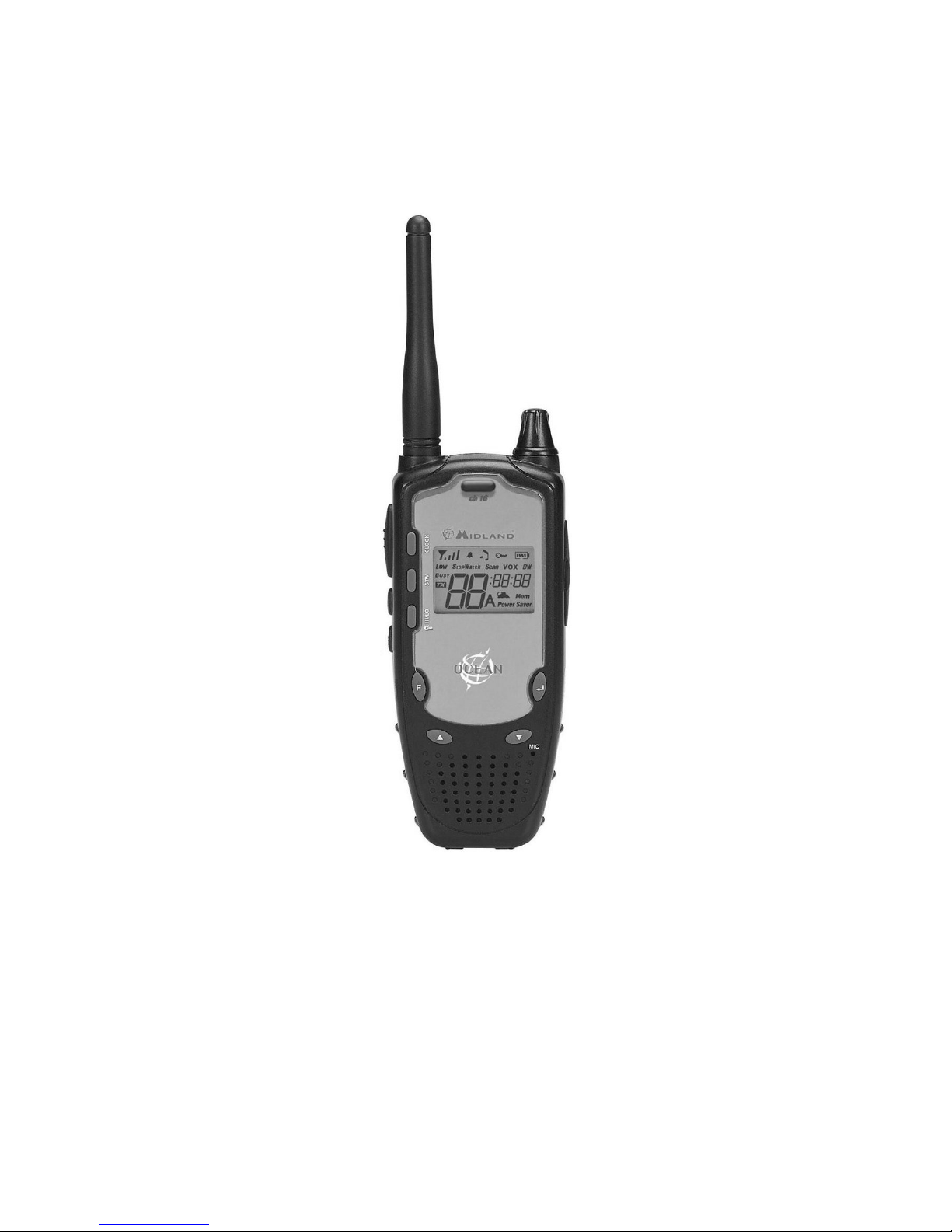
Ocean
Handheld VHF Marine Transceiver
USER’S MANUAL
Page 2

Page 2 of 24
Table of Contents
1 INTRODUCTION .......................................................................................................................................... 3
2 ABOVE ALL… SAFETY! .............................................................................................................................. 4
2.1 Symbols used......................................................................................................................................................................4
2.2 Warnings.............................................................................................................................................................................4
2.2.a General...................................................................................................................................................................4
2.2.b Batteries .................................................................................................................................................................4
2.3 Assistance...........................................................................................................................................................................5
3 DESCRIPTION OF PARTS............................................................................................................................. 6
3.1 Description of parts and commands....................................................................................................................................6
3.2 Display symbols ..................................................................................................................................................................7
4 PREPARATION........................................................................................................................................... 9
4.1 Connecting/removing the antenna ......................................................................................................................................9
4.1.a Connecting the antenna: ........................................................................................................................................9
4.1.b Removing the antenna: ..........................................................................................................................................9
4.2 Fastening/removing the belt clip..........................................................................................................................................9
4.3 Installing/removing the batteries..........................................................................................................................................9
4.3.a To install the batteries: .........................................................................................................................................10
4.3.b To remove the batteries:.......................................................................................................................................10
4.4 Recharging the batteries...................................................................................................................................................10
4.4.a Standard MW904 wall battery charger.................................................................................................................10
4.4.b RC445 Intelligent, table-top battery charger.........................................................................................................11
4.5 Proper use of rechargeable batteries................................................................................................................................11
4.5.a Memory effect.......................................................................................................................................................11
5 STANDARD FUNCTIONS ............................................................................................................................ 12
5.1 Turning Ocean on/off.........................................................................................................................................................12
5.2 Volume regulation .............................................................................................................................................................12
5.3 Selecting a channel...........................................................................................................................................................12
5.4 Transmission and reception..............................................................................................................................................12
5.4.a Reception .............................................................................................................................................................12
5.4.b Transmission........................................................................................................................................................12
5.5 Monitor function.................................................................................................................................................................13
5.6 Selecting transmission power............................................................................................................................................13
5.7 Instant recall of channel 16 ...............................................................................................................................................13
5.8 Display lighting..................................................................................................................................................................13
5.9 Keypad lock.......................................................................................................................................................................13
5.10 Use of CALL button...........................................................................................................................................................13
5.11 Clock mode .......................................................................................................................................................................14
5.11.a Setting the time.....................................................................................................................................................14
5.12 Chronometer mode ...........................................................................................................................................................14
6 ADVANCED FUNCTIONS (F BUTTON).......................................................................................................... 15
6.1 Activating/deactivating keypad tones................................................................................................................................15
6.2 VOX mode.........................................................................................................................................................................15
6.2.a Activation/deactivation of VOX mode...................................................................................................................15
6.2.b Setting VOX sensitivity.........................................................................................................................................15
6.2.c Setting VOX delay ................................................................................................................................................16
6.3 Scanning functions............................................................................................................................................................16
6.3.a Scanning on all channels......................................................................................................................................16
6.3.b Activating Dual Watch ..........................................................................................................................................16
6.4 International, U.S.A. and Canada Bands ..........................................................................................................................16
6.5 Memory channels..............................................................................................................................................................17
6.5.a Programming of memory channels.......................................................................................................................17
6.5.b Memory recall.......................................................................................................................................................17
6.5.c Memory scanning .................................................................................................................................................17
6.6 Weather channel (only with the USA band) ......................................................................................................................17
6.7 Automatic weather information warning (detection of NOAA tone)...................................................................................17
7 PROGRAMMING AND SELCTION OF PRIVATE CHANNELS ........................................................... 18
8 CLEANING AND MAINTENANCE OF YOUR RADIO.......................................................................................... 18
8.1 Cleaning the radio.............................................................................................................................................................18
8.2 Connectors........................................................................................................................................................................18
9 TROUBLESHOOTING.................................................................................................................................20
9.1 Reset of functions..............................................................................................................................................................20
9.2 Solution table.....................................................................................................................................................................20
10 OPTIONAL ACCESSORIES ..................................................................FOUT! BLADWIJZER NIET GEDEFINIEERD.
11 TECHNICAL SPECIFICATIONS .................................................................................................................... 22
12 FREQUENCY TABLE.................................................................................................................................. 23
Page 3

Page 3 of 24
1 INTRODUCTION
Congratulations on choosing Ocean! Your handheld marine transc eiver was designed as a high-quality, robust, and
reliable marine radio, using the latest technology availabl e. Ocean ensures secure transmission and reception on all
VHF marine channels, as required by the International Telecommunications Union (IT U). Your transceiver is composed
of the highest-quality electronic components, conforms to EN 301 178-2, CE/99/05 re gulations, and is water resistant
(splashproof), ensuring clear, reliable communication for many years. Ocean is equipped with a microprocessor, which
controls not only the marine band tuning, but also many advanced functions such as Dual Watch and memory channels.
The following are the principal features of your transceiver:
• PLL (Phase Locked Loop) synthesizer circuit – for precise and stable channel selection.
• Large, back-lit LCD display – constantly displays Ocean’s parameters and settings. The backlighting enables you to view the
screen in case of little environmental light.
• Automatic squelch– while in standby, this function automatically eliminates bothersome background noise.
• Automatic Power Saver – saves energy when in standby, prolonging battery life.
• Recall button for Channel 16 – for instant access to channel 16 (the universal marine channel for emergency contact).
• Channel scanning – automatically searches for marine band channel signals.
• Dual Watch – for monitoring of radio traffic on two channels simultaneously.
• VOX (Voice Operated eXchange) – activates transmission when the user begins speaking. When used with optional microphone
accessories, this feature enables the user to operate hands-free, clipping the transceiver to a belt.
• Call button – briefly sends the transceiver into transmission mode, generating audio call tones.
• Clock and chronometer – enables the user to view the current time on the LCD display and to use the transceiver as a
chronometer that is precise to the hundredths of a second.
• High/low power selection – reduces transmission power in short-distance communication, allowing Ocean to save energy and
reducing the risk of interference.
• Multifunctional bar indicator– in reception mode, this function indicates the incoming signal strength using a series of bars. In
transmission mode, it indicates the output power.
• Battery level indicator – constantly displays the battery level.
• Keypad lock – locks the transceiver keypad to avoid the accidental activation of buttons or settings.
• 20 memories – for storing, rapid recall, and scanning of your 20 most-used channels.
• Power is supplied through 4 normal AA batteries – the (optional) batteries can be either recharge able or alkaline, for maximum
flexibility of use and operating cost.
• Sockets for speaker, microphone, and battery charger (SPK, MIC CHG) – these sockets enable the use of various
microphone accessories (headphone, microphone/speaker, etc), as well as the use of an optional standard “MW904” wall battery
charger.
• 20 private channels – using the optional PRG-OCEAN program, you can program 20 channels within the VHF marine band.
The manufacturer, with its effort to constantly improve product quality, reserve the right to change characteristics and features
without prior notice.
Page 4

Page 4 of 24
2 ABOVE ALL… SAFETY!
2.1 Symbols used
For ease and convenience of use, this manual uses symbol s to highlight urgent situation s, practical advice, and gener al
information.
! Symbols such as this one indicate a crucial description regarding technical repairs, dangerous conditions, safety
warnings, advice, and/or other important information. Ignoring these s ymbols may result in serious problems and/or
damage and/or personal injury.
Notes such as this one indicate practical advice that Midland suggests be followed for the optimal performance of Ocean.
Important sentences and words have been underlined.
2.2 Warnings
2.2.a General
! Before using the transceiver, carefully read all the instructions contained in this manual in the order in which they are
written. Cross-references to paragraphs and chapters are provided for ease of use only. After reading, keep this manual
for future reference.
! Read and follow all the warning and instruction labels found on the radio and its accessories.
! Always observe laws and regulations regarding the use of marine transceivers, which may change according to the
country you are in. Where prohibited, or in areas where the radio may cause interference or danger, turn off your radio.
! Do not transmit without an antenna connecte d – although the radio is protected, this may seriously damage its R.F.
power stages. Do not use your transceiver if the antenna is damaged.
! Keep the antenna at least 2.5cm from your head a nd bod y during trans mission, and keep a dista nce from other el ectrical
devices. Your transceiver contains a radio transmitter. Be aware that, w hen you press the PTT button, the radio emits
radio frequency (RF) energy. If you use cardiac stimulators, hearing aids, or other medical devices, consult your
physician or the manufacturer of the device to ensure the de vice is adequatel y protected from RF e nergy. Your p hysician
will be able to suggest ways of obtaining this information.
! Keep a tight grip your radio (a fall may damage it) and ensure the PTT button is not pressed accidentally when you do not
need to transmit. Do not hold the transceiver by the antenna ! This is a delicate part of the device and is vital for the
proper functioning of the radio.
! Pay attention to environmental conditions – alt hough Ocean was designe d to operate u nder the most se vere conditions,
it is important to avoid exposure to environments that are excessively humid or dusty, or to temperatures outside the -15
to +55°C° range. Also avoid exposure to direct sunlight, jarring, and excessive vibration.
! Before using the radio, ensure that all protective covers and parts are in perfect o perating condition, in order to ensure
maximum protection against humidity and atmospheric agents.
! Although this radio was designed to be water resistant, avoid getting it w et as much as possible and do not let any
liquids fall on it. If the transceiver or one o f the accessories gets wet, dry it off as soon as possible with a soft, clean
cloth. If you feel that liquid may have penetrated the radio’s housing, contact a service centre for a diagnostic check.
! Do not use the radio, its accessories, and/or sub stitute the batteries in potentially explosive environments. A single
spark may cause an explosion.
! Do not open the radio for any reason! Ocean’s precision mechanics and electronic s require experience and specialized
equipment; for the same reason, the radio should u nder no circums tances be realigne d as it has alread y been calibrated
for maximum performance. Unauthorized opening of the transceiver will void the warranty.
! Use original accessories only; otherwise you may seriously damage your handheld transceiver.
! Turn off the radio before cleaning it. For further information, refer to Chapter 7.
2.2.b Batteries
! Before using the battery charger, carefully read all notes and cautions regarding this equipment.
! Do not short-circuit the battery terminals: doing so may result in fire, burns, or explosions.
Page 5

Page 5 of 24
! Never throw batteries into a fire or expose them to high temperatures; doi ng so may cause fires or explosions. Always
follow the regulations set out by your country of residence.
! Use only the original batteries and battery charger. Use of unapproved accessories may cause burns, fires, or
explosions, and may create serious damage to the radio/batteries or to people.
! The battery charger should only be used indoors.
! Ensure your power supply conforms to the one required for your battery charger ( AC adaptor). If you are unsure, check
with your vendor or your local electricity supplier.
! To avoid damaging the power cord to your batter y charger, connect it in a place where it will not be stepped on and
where nothing will be placed on top of it. Insert the prongs into a socket that has been grounded.
! Avoid shocks and excessive vibrations. Do not use the batter y charger if it has been subjected to strong shock, had a
fall, or appears damaged; immediately contact an authorized service centre.
! Do not dismount the battery charger. Any repair work must b e performed exclusively by authorized s ervice centers. For
further information, contact your local supplier.
! To reduce the risk of electrical shocks, disconnect t he power cable before performing cleaning or maintenance. Gras p
the plug (not the cord!) when removing it from the socket. Use of inappropriate extension cords may cause fire or
electrical shocks.
! Do not expose the batteries directly to temperatures outs ide the -20°C to +35°C range during storag e and do not charge
them in temperatures outside the +5 to +55°C range.
2.3 Assistance
We advise you to write the serial number of yo ur transceiver in the space provided bel ow. This number is found on the
rear panel of the transceiver and will be useful in the event of repair/assistance and/or loss and/or theft.
! Serial number_______________________
Page 6
Page 6 of 24
3 DESCRIPTION OF PARTS
3.1 Description of parts and commands
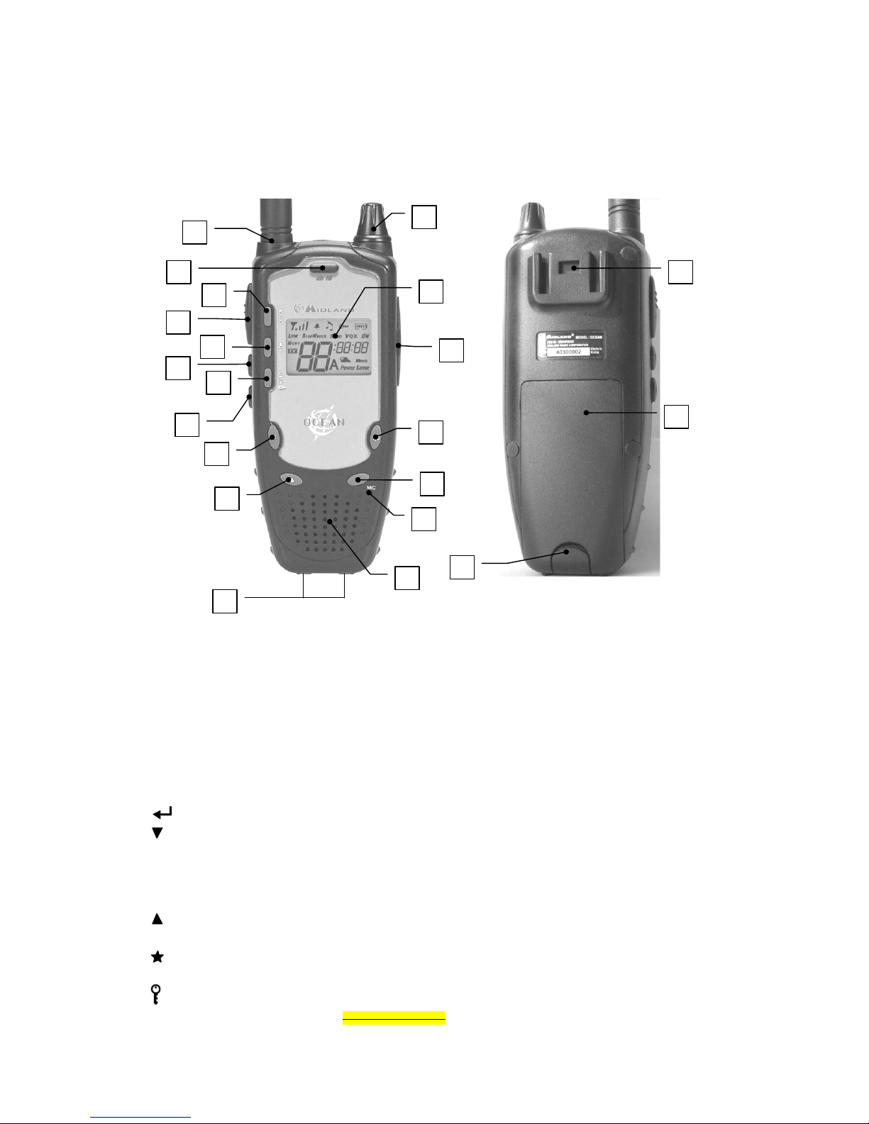
Refer to the following pictures to locate and get familiar with the various parts of Ocean:
1) Antenna connector (SMA type). For attaching the rubber ducky antenna provided.
2) ON/OFF/VOLUME knob – turns the equipment on/off and adjusts audio volume reception.
3) LCD display – the LCD (liquid crystal) display constantly displ ays the operating status of Ocean and functions
currently in use.
4) SPK, MIC CHG, and DATA sockets (on the radio’s side, under a protec tive rubber flap) – perform the following
functions:
• SPK and MIC CHG – jack sockets respectively for the speaker and external microphone. Used together, these are used
for connection of optional accessories, such as microphones, speakers, head/earphones, etc. Also, the MIC CHG socket
is used for connecting the (optional) standard MW904 wall battery charger. For further details regarding optional
accessories, please refer to Chapter Fout! Verwijzingsbron niet gevonden..
• DATA (channel programming) – used by the supplier or service centre for programming private channels; their use must
be previously authorized by the appropriate local authorities.
5) button – confirms the selected setting.
6)
button – for scrolling downwards numerically through the tuned marine channels and for setting functions.
7) Internal microphone – the transmission microphone is located here.
8) Internal speaker – the reception speaker is located here.
9) Contacts for battery charging (bottom of the radio) – for connecting the (optional) RC445 intelligent, table-top
battery charger.
10)
button – for scrolling upwards numerically through the tuned marine channels and for setting functions.
11) F (Function) button – for accessing the various programming functions and settings of the radio.
12)
button/M (Monitor) – activates display backlighting, and excludes (temporarily or permanently) the circuit
which silences the receiver in the absence of signals (squelch) so as to receive signals that are extremel y weak.
13)
HI/LO button – selects high or low transmission power, and activates/deactivates the keypad lock.
14) CALL button – sends an audio call (4 two-tone bleeps) on your currently selected channel.
18
2
3
5
6
10
11
12
13
15
16
17
21
9
20
19
7
8
14
4
1
Page 7
Page 7 of 24
15) STW (Stop Watch - Chronometer) button – recalls the chronometer function.
16) PTT (Push To Talk) button – when pressed, this button sends the transceiver into transmission.
17) CLOCK button – recalls the clock function.
18) Ch 16 button – instantly recalls channel 16.
19) Belt clip fastener – for connecting the radio to the belt clip.
20) Cover of battery compartment – it holds four AA batteries (rechargeable 1.2V NiMH, or alkaline 1.5V) to supply
your handheld transceiver.
21) Clasp on battery compartment – holds the battery compartment cover in place.
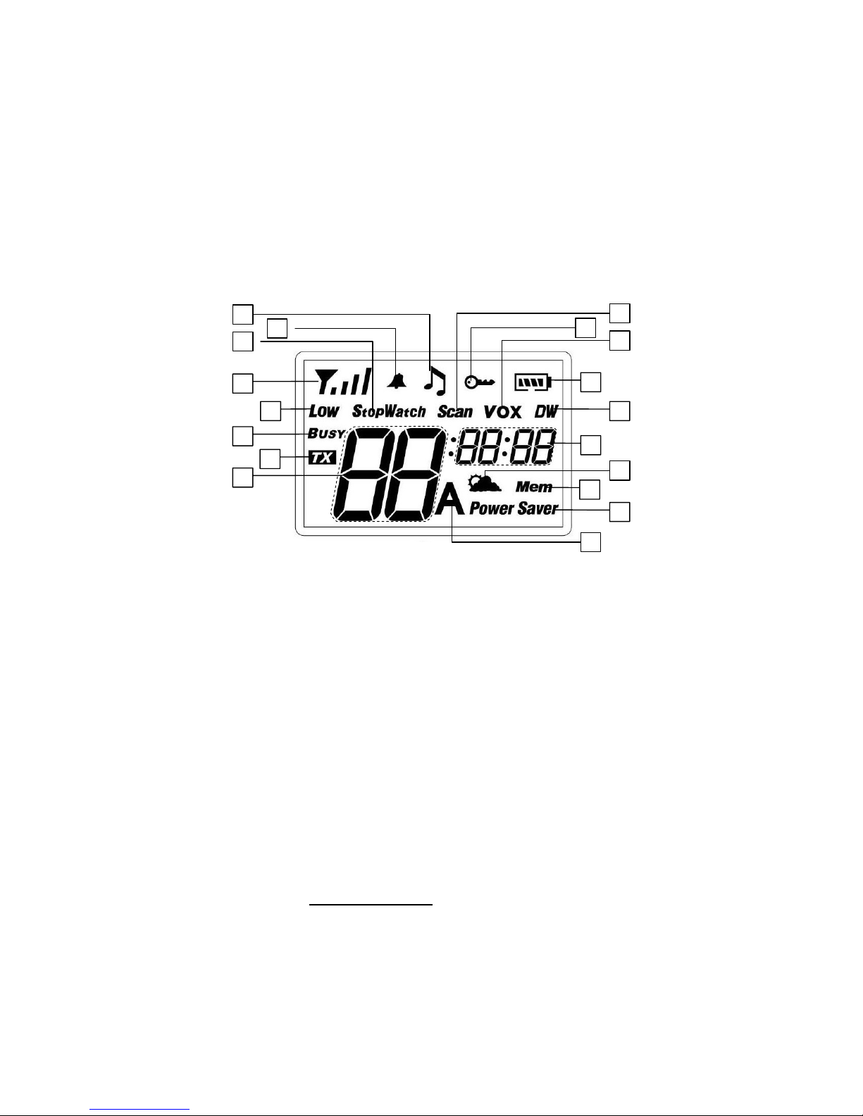
3.2 Display symbols
Your marine transceiver is fitted with an LCD (liquid crystal) display to keep you up to date on its operating status. The
symbols and parameters that may appear are outlined below:
A) Field strength indicator /relati ve transmission power – during reception, this displays the strength of the signal
received. During transmission, it indicates the relative output power. The level indicated is proportional to the number
of bars seen.
B) StopWatch (chronometer) – app ears on the display when the chronometer function is activated.
C) Call – indicates that the two-tone audio call is activated (the CALL button is pressed).
D) Keypad tones – indicates the activation of tones to confirm when buttons are pressed.
E) Scan - appears when the transceiver is performing channel scanning.
F) Keypad lock – indicates that the keypad is locked.
G) VOX – appears on the display when the VOX (Voic e Operated eXchange – hands-free transmission) function is
activated.
H) Battery level – indicates the remaining battery power. The four bars disappear proportionately as power decreases.
When the battery charge is no longer high enough to guarantee correct functioning of the transceiver, this icon will
flash to signal that the batteries need to be recharged (or replaced).
I) DW – the transceiver is performing in Dual Watch mode.
J) These small numbers indicate different data according to the function selected, such as the memory channel
selected, the band selected (INT, USA, CANADA), etc.
K) Weather channels/information (only on the USA band) – indicates that you are receiving on a weather channel, or
that the channel you have selected is currently transmitting weather information.
L) Mem – indicates that you are using one of the programmed memories from your most-used channels.
M) Power Saver – appears when the power saver is active.
N) A icon (only with the USA band) – this icon indicates when an A channel has been set from the North American
band.
O) These two large numbers indicate the marine chan nel currently selected. During regulation of sensitivity or delay in
R
B
D
Q
P
C
F
G
A
H
E
I
J
L
K
N
M
O
Page 8

Page 8 of 24
VOX mode, they will read as LE (level) or dL (delay).
P) TX - appears when the radio is transmitting.
Q) BUSY – appears when the transceiver is receiving a signal.
R) LOW – indicates that low transmission power has been selected.
Page 9

Page 9 of 24
4 PREPARATION
Before using your transceiver, ensure that your package contains:
• The transceiver
• The flexible, rubber ducky antenna with SMA connector
• The belt clip
• The user’s manual (this manual)
If any part is missing or damaged, contact your supplier as soon as possible.
In order for the device to function, you will require four AA ba tteries, either 1.2V NiMH rechargeable or 1.5V non-rechargeable
alkaline. For further details, refer to par 4.3.
To charge the Ni MH batteries without taking them out of the radio, a standard MW904 wall charger is available, as well as a
RC445 intelligent table-top charger. For further details, refer to par. 4.4.
4.1 Connecting/removing the antenna
4.1.a Connecting the antenna:
1) Hold the transceiver in one hand, with the antenna connector facing upwards; pick up the flexible, rubber ducky
antenna by its base (the larger end, with the SMA connector).
2) Orientate the base of the antenna in the direction of the transceiver’s antenna connector.
3) Screw the antenna into the antenna connector, turning it clockwise until it is firmly in place.
, Do not tight too much the antenna: doing so may damage the threaded connector on the radio or the
antenna itself.
4.1.b Removing the antenna:
1) Follow step 1 outlined in paragraph 4.1.a
2) Unscrew the flexible, rubber ducky antenna, turning it counter-clockwise and removing it.
! Avoid transmitting without the antenna con nected or with a da maged antenna. Although the radio is protected, doing so
may seriously damage the R.F. power stages. Use the radio only with the antenna.
4.2 Fastening/removing the belt clip
The rear belt clip allows the user to easily clip the transceiver to a belt. However, it may be necess ary to remove the clip
in order to make easier the radio maintenance or battery substitution. To fasten the clip to the radio, position it above the
groove found of the back of the transceiver, then drag it downwards until it locks into place. To remove the clip from the
belt, lift the release lever and drag the clip upwards until it comes free.
! Ensure the belt clip is correctly attached; otherwise the transceiver may become unattached accidentally and fall.
4.3 Installing/removing the batteries
The transceiver operates with four AA batteries (not included). There are two battery options available:
• Rechargeable 1.2V NiMH – available in various capacities (in mAh). Higher battery capacity allows for greater duty, but
requires longer recharging time.
• Non-rechargeable 1.5V alkaline.
For installing/removing the batteries, it is not necessary to remove the belt clip (procedure outlined in par. 4.2), however, this does
make it easier to access the batteries.
! Do not install a combination of rechargeable and alkaline batteries in your transceiver. Always use 4 AA batteries of the
same type, brand, and from the same stock. Always use the same batteries as a set in order to ensure their le vel of
charge is the same.
! If you are not using the transceiver for an extended period, remove the batteries.
Page 10

Page 10 of 24
4.3.a To install the batteries:
1) Carefully unhook the rear clasp by slightly raising it
and catching the depression with a fingernail, then
rotating the clasp downwards.
2) Carefully lift the rear protective cover from the
battery compartment and remove it.
3) Insert the batteries (rechar geable or alkaline) in the
battery compartment, ensuring the batteries are
correctly oriented in their polarity, as indicated on the
inside of the battery compartment.
4) Carefully insert the cover’s tabs into the slots at the
top of the battery compartment, and then slowly
press the cover down against the battery
compartment until it is perfectly aligned with the
transceiver body.
5) Carefully return the clasp onto the protective cover, pressing until it clicks into place.
! Ensure you have properly closed the battery compartment cover.
4.3.b To remove the batteries:
1) Follow steps 1 and 2 as outlined above.
2) Remove the batteries from the radio.
3) Follow steps 4 and 5 as outlined above.
4.4 Recharging the batteries
Two types of battery chargers are available. Each one is able to charge NiMH batteries without removing them from the
radio:
• Standard MW904 wall battery charger – this is the least expensive. It supplies a slow charge, allowing for maximum battery
life. For further details, refer to par. 4.4.a.
• RC445 intelligent table-top battery charger – for rapid charging and greate r flexibility of use. It also monitors the charge, and
once batteries are charged, switches to trickle charging. For further details, refer to par. 4.4.b.
New batteries do not immediately allow for maximum duty, as they must be “run in” through at least 3 complete cycles of
charge/discharge.
! Use the battery charger only if you have installed four rechargeable NiMH batteries. Never attempt to char ge other types
of batteries (particularly alkaline) – doing so may cause explosions or personal harm.
! Read the battery usage warnings outlined in par. 2.2.
4.4.a Standard MW904 wall battery charger
1) Ensure the radio is turned off (it must remain off for the entire period of charging).
2) Carefully lift the rubber flap on the right side of the tr ansceiver, slipping a fingernail into the
center left part, and rotating it towards the right, as indicated in the figure.
3) Insert the plug at the end of the MW904 batter y charger cable into the MIC CHG socket, then
connect the battery charger to an AC power source.
4) Once the batteries are charged (see table belo w for charging times), disconnect the battery
charger from the AC power source, then disconnect the transceiver from the battery charger.
5) Return the rubber flap to its place.
Code Battery capacity
(mAh)
Time
(hours)
C696 1.200 8
C697 1.700 11.5
C734 2.300 15.5
TABLE OF APPROXIMATE TIMES FOR COMPLETE RECHARGE,
ACCORDING TO THE BATTERY TYPE USED.
! Do not overcharge the batteries! When the batteries are completely charged, the charging process does not stop
automatically. Do not forget to disconnect the transceiver from the ba ttery charger as soon as possible after chargi ng is
complete, otherwise you may seriously damage the batteries and/or the transceiver.
! For successive charging, longer duty, and battery life, refer to par. 4.5.
! Do not forget to replace the rubber flap after charging.
1
2
Page 11

Page 11 of 24
4.4.b RC445 Intelligent, table-top battery charger
This battery charger is able to rapidly charge batteries and to detect when the charging is complete, switching
automatically the trickle charge.
1) Insert the transceiver, with the charging contacts facing do wnwards, into the RC445 battery charger slot, then
connect the battery charger to an AC power source. Charging will begin, and an LED indicator will light up.
2) Once charging is complete, a green LED light will appear on the battery charger, indicating the operation is
complete and the device has switched the trickle charge.
3) When possible and for increased security, remove the transceiver from the charging slot and disconnect the
battery charger from the AC power source.
! For successive charging, longer duty, and battery life, refer to par. 4.5.
4.5 Proper use of rechargeable batteries
When possible, recharge batteries only when at least two of the icon bars have disappeared (the icon should indicate
). Be aware that charging time will be shorter in proportion to the amount of residual charge remaining in the
battery, therefore, when only two bars appear in the ico n, this indicates you will require about 50% of time indicated on
the table in par. 4.4.a. This is particularly important if you use the MW904 standard charger, otherwise you risk
overcharging the batteries.
If you use the batteries properly, you will obtain at least 400 cycles of charge/discharge at maximum duty. It is normal for
battery duty to gradually decrease after about 2/3 of the battery’s life.
Rechargeable battery packs lose their charge over time even if they are not used (auto-discharge); this is normal. A NiMH (Nickel
Metal Hydrate) battery may lose 10 – 20% of its energy within a few days.
4.5.a Memory effect
Rechargeable NiMH (Nickel-Metal-Hydrate) batteries are vi rtually unaffected by the “memory effect”. This phenomenon
is associated with a drastic reduction of battery autonomy and is triggered if the batteries are regularl y charged before
having lost at least 50-75% of their power and/or are not completely recharged. To avoid the memory effect:
• When possible, recharge the batteries only when they are completely discharged; i.e. when the battery indicator will be
flashing.
• Do not disconnect the battery charger before the time indicated for complete battery charging.
• Discharge and recharge your batteries completely at least twice a month.
In any case, the best solution for avoiding the memory effect is to use in turn t wo battery sets: one in use, and the other
being charged as spare set.
The memory effect can be easily eliminated by completely charging/discharging the batteries 3 or 4 times.
The memory effect should not be confused with the normal battery life, which is 400 cycles of charge/discharge on average. It is
completely normal for operating duty to decrease when the batteries have reached the end of their life; at this point, you will need
to substitute the battery set.
Page 12

Page 12 of 24
5 STANDARD FUNCTIONS
5.1 Turning Ocean on/off
To turn on the transceiver, turn the ON / OFF / VOLUME knob clockwise until it clicks on: the LCD display will come on,
and you will hear a beep (acoustic signal).
The LCD display backlighting will automatically turn off after approx. 10 seconds in order to save energy, though the display itself
will remain active.
To turn off the transceiver, turn the knob counter-clockwise until you hear another click.
5.2 Volume regulation
Bring the ON / OFF / VOLUME knob to medium. Once the transceiver receives a signal, adjust the volume to a
comfortable level. If no signal is received, use the
/M button as described in par. 5.5.
5.3 Selecting a channel
Press the or buttons respectively to scroll up or down through the marine channels until finding the desired
channel. To scroll quickly through the channels, hold down the
or button until you reach the desired channel.
The marine band does not include some channel numbers. Refer to the frequency table in Chapter 11. Furthermore, channels may
have a frequency reception that is different from the transmission one (duplex channels) or it is the same (simplex channels).
Normally, communication between vessels can only take place on simplex channels.
! Your transceiver is preset on international channels. Depending on the cou ntry you are in, it is your responsibility to
select INT or USA channels, depending on the local regulations in order to avoid i nterference. For f urther details, refer to
par. 6.4.
5.4 Transmission and reception
During transmission and reception, ensure the ant enna is as vertical as possible and is free from obstacles in the direction of your
party.
5.4.a Reception
When the PTT is not pressed, the radio is in reception and is ready to receive incoming communic ation on the currently
tuned channel (stand-by). If you are not receiving communications in stand-by and have not activated a ny commands for
at least 10 seconds, the display will flash Power Saver, indicating that the power saver function has been automaticall y
activated. The radio will remain ready to receive signals. In this case:
• The BUSY icon will appear on the display, along with the icon, which indicates the strength of the incoming signal (the
number of bars being proportional to the strength of the signal).
• The device which silences the audio in the absence of signals (squelch) will automatically disable. If reception happens to be
broken, try to use the monitor function as described in par. 5.5.
5.4.b Transmission
The PTT (push to talk) button is located on the top left of your Ocean. To transmit:
1) Ensure the channel you’v e selected is not a reception-onl y channel (if it is, the transmission will be disabled) and
that no one else is talking (this will appear on your display as the B
USY icon).
2) Hold down the PTT button:
will appear on the display, and the icon will indicate your relative
transmission power (the number of bars is proportional to your relative transmission power).
3) Wait a second, then speak in a normal voice, facing the transceiver’s microphone at a distance of approx. 5 cm.
4) When you h ave completed your messag e, release the PTT button: and will disappear from the display
and the transceiver will return to reception mode.
Obviously, you can only communicate with stations that are tuned on the same channel.
If the BUSY icon appears on the display, but you don’t hear anything, you may have accidentally turned the volume to the minimum
level.
Page 13

Page 13 of 24
5.5 Monitor function
The /M (Monitor) button is for temporarily excluding (opening) the circuit which silences the receiver in t he absence of
signals (squelch) in order to listen for e xtremely weak sig nals that can ’t open the squelch stably. In this mode, you avo id
listening to broken communication.
To activate the monitor function, hold down the
/M button until you hear background noise (or else a weak signal).
Release the /M button when you hav e finished listening.
If you wish to keep the squelch open for longer periods without holding down the button, press the /M button for at least 5
seconds, until you hear two acoustic sounds (beeps), then release the button. The squelch will remain open until you briefly press
the
/M button again.
5.6 Selecting transmission power
The transmission phase absorbs the most energy. To extend the batter y duty, you can select low transmission power
when transmitting over short distances. To do this, briefly press the HI/LO button: L
OW will appear on the display (low
power is approx. 0.5 W). If you wish to transmit or receive over long distances or with weak signals, press the HI/Lo
button again: L
OW will disappear and high power will be selected (approx. 2W).
The transceiver is factory preset on high power.
5.7 Instant recall of channel 16
Channel 16 is used as the universal marine channel for emergency comm unication. Your transceiver is equipped with a
button that provides instant access to this channel. To instantly recall channel 16, press the ch 16 button. Channel 16 will
be selected (regardless of the usage mode selected, except for scanning). To return to th e channel selected previo us to
channel 16, press the ch 16 button again.
5.8 Display lighting
If environmental light is insufficient for reading the display, you can activate the backlighting for 10-s econd intervals by
briefly pressing the /M button. If you wish to deactivate back lighting before t he end of th is pre-set time, pr ess the /M
button again.
Display lighting absorbs additional battery energy. Try to use this feature in moderation.
5.9 Keypad lock
During transport, you can block the transceiver’s keypad in order to avoid accidental activation of the functions. To
activate the keypad lock, hold down the
HI/LO button until the s ymbol appears on the display. This function
deactivates all the buttons on the front of the transceiver. Pressing one or more buttons when in this mode will cause an
audio signal of thee consecutive beeps. To deactivate the keypad lock and therefore reactivate the functi on keys, follow
the description above once again.
5.10 Use of CALL button
The CALL button is used to make a call on the channel currently selected and is composed of four two-tone audio
sequences (bleeps). To use this function, briefly press the CALL button. The radio will go into transmission mode for
approx. two seconds, emitting a call. While this is happening, (call) and (transmission) will appear on the
display, as well as the
indicator, showing your relative transmission power.
Two-tone calling is a special function of Ocean. As such, your party may not recognize it. We suggest that you ensure your party is
aware that you will be activating this function before use.
Page 14

Page 14 of 24
5.11 Clock mode
This mode allows the user to see the current time on the LCD display. To activate this, briefly press the CLOCK button.
5.11.a Setting the time
1) In clock mode, briefly press the
button. The hour will begin to flash on the LCD display.
2) Press the
or buttons to change the hour.
3) Briefly press the
button again. The minutes will begin to flash on the LCD display.
4) Press the
or buttons to change the minutes.
5) Briefly press the
button again. The seconds will begin to flash on the LCD display.
6) Press the
or buttons to change the seconds.
7) Briefly press the
button to set the time and return to clock mode.
8) To exit the clock mode, briefly press the CLOCK button.
While in this mode, you can still transmit normally using the CALL or PTT buttons. When this happens, the LCD display will
automatically switch to its regular operating screen, returning to clock mode as soon as transmission is terminated.
5.12 Chronometer mode
This function activates the use of your transceiver’s built -in chronometer (values to the hundredths of a second). To
activate this:
1) Press the STW (Stop Watch) button: StopWatch and 00
:00:00
will appear on the display.
2) To activate the chronometer, press the
button. At this point, you can:
• View the elapsed time, by pressing the button. To exit the elapsed time viewing, press the button again.
• Stop the chronometer by pressing the
button. To reactivate the chronometer from its stopping point, press the
button again. Or else press the
button if you wish to restart the chronometer at 00
:00:00
.
3) To exit the chronometer function, press the STW button again.
When the chronometer function is active, Ocean is still able to receive calls, but the display will continue to show the
chronometer’s progress. When this happens, you can transmit normally using the CALL or PTT buttons, or using VOX mode. The
display will switch to the regular operating screen, but will continue to clock the chronometer’s progress. To return to the screen
after terminating transmission, press the STW button again.
When the chronometer function i s active, if you press the CALL button to send a call, the radio will show the main screen during
the call but will continue to clock the chronometer’s progress, which will appear on the display immediately afterwards.
Page 15

Page 15 of 24
6 ADVANCED FUNCTIONS (F BUTTON)
The F button enables the user to access the transceiver’s advanced functions and to change settings as required:
selecting the band (INT, USA, or CANADA), VOX mode, memory programming and recall, channel scanning, etc. In
general terms, to recall/change settings for various functions:
1) Press the F (Function) key repeatedly to scroll through the available functions, until you find the one you want.
2) Press the or buttons to set the function currently on the screen. Depending on the function, you can s elect
On (function activated), Off (function deactivated), or scroll through the various values (e.g., from 01 to 06).
3) To store a changed setting, press either the
or the F button. Both will perform the same operation, the
difference being that the returns the radio to Standby, while F selects the next function.
After following step 1, you must make any changes you wish to within 10 seconds of each button pressing, otherwise the radio wi ll
return to standby and will storing with the current settings.
6.1 Activating/deactivating keypad tones
Keypad tones are emitted each time a button is pressed in order to reduce the likelihood of accidentall y pressing a b utton
twice. This function can be deactivated if you prefer the radio to be sile nt. To activate or deactivate the keypad tones,
refer to the steps outlined below:
1) Repeatedly press the F key until the
icon begins flashing. Below this icon, the current setting will also flash (On
= tones activated or Off = tones deactivated).
2) Press the or buttons to change the keypad tone to On or Off.
3) Press the
button to confirm the setting change and return to Stand-by, or press the F key to access the
following menu setting.
6.2 VOX mode
VOX (Voice Operated eXchange) enables the user to activate hands-free transmission (without pressing any buttons)
simply by speaking into the microphone. As such, the user is able to rest the radio on a nearby surface and speak a shor t
distance from the microphone, communicating hands-free.
VOX functions best with the optional microphone accessories available, which connect to the SPK and MIC CHG jacks.
Using these accessories, the microphone will always be c lose to the user’s mouth, and apart from the convenience of
being hands-free, this will give the user an even greater rang e of movement, especially with the radio clipped onto the
user’s belt.
VOX is equipped with two settings (sensitivity and delay), which allow for optimal use, as explained below.
! If you use an external microphone, once you have finished using it, do not f org et to replac e th e rubberized pr otective flap
on the radio.
6.2.a Activation/deactivation of VOX mode
1) Repeatedly press the F key until the VOX icon flashes. B elow this icon, the currently selecte d setting will appear
(On = VOX activated or Off = VOX deactivated).
2) Press the or buttons to change the VOX mode to On or Off.
3) Press the
button to confirm the setting change and return to Stand-by, or press the F key to access the
following menu setting.
6.2.b Setting VOX sensitivity
Adjusting the VOX sensitivity avoids the likelihood of the radio goi ng into transmission mode because of environmental
noise. As such, it should be adjusted to the minimum level necessary to activate transmission by voice.
1) Repeatedly press the F key until the LE (sensitivity level) icon flashes. The VOX icon and the sensitivity level
currently selected (from 01 to 06) will flash on the display.
2) Press the or buttons to select the desired level (01 = more sensitive, 06 = less sensitive).
3) Press the
button to confirm the setting change and return to Stand-by, or press the F key to access the
following menu setting.
Page 16

Page 16 of 24
6.2.c Setting VOX delay
During transmission with VOX, a delay avoids the possibility that, during short pauses in commun ication, this function
does not return the radio to reception mode. As such, this function should be set at the minimum level necessary to
guarantee this.
1) Repeatedl y press the F key until the dL (delay) appears. The VOX icon and the delay currently selected (from 01
to 06) will flash on the display.
2) Press the
or buttons to sele ct the desired delay time. Six delay values are available, in incr ements of 0.5
seconds (01 = 0.5 seconds, 06 = 3.0 seconds).
3) Press the
button to confirm the setting change and return to Stand-by, or press the F key to access the
following menu setting.
6.3 Scanning functions
6.3.a Scanning all channels
Ocean can automatically search for signals throughout the marine band by scanni ng, i.e. selecting the channels in rap id
sequence. When a signal is detected, the scanning pauses on that channel and remains blocked until the signal ends
(for a maximum of five seconds), giving the user a chance to respond to a call, if n ecessary, before Ocean automatically
begins scanning again. To begin scanning, follow the steps outlined below:
1) Repeatedly press the F key until the Scan icon and the currently selected channel begins flashing on the display.
2) Press the or buttons to activate scanning. The transceiver will b egin to explore the marine band channels.
3) The transceiver will continue channel scanning until it picks up a transmission. When this happens, the
transceiver temporarily halts scanning and remains tuned on that chan nel for about 5 seconds. During this time,
you have a few options:
• If the communication does not interest you, wait for 5 seconds or press the or keys to begin channel scanning
again.
• If the communication interests you, you can halt scanning by briefly pressing the
or PTT buttons.
4) To exit the scanning mode and return to Stand-by on the currently selected channel, press the button, or
press the F button to access the following menu setting.
Scanning can also be executed on commonly-used channels only. For further details, refer to par. 6.5.c.
6.3.b Activating Dual Watch
The Dual Watch function allows you to virtually watch simultaneously two channels of your choice by executing a scan
on the two channels. To select the Dual Watch function, follow the steps outlined below:
1) First, select a channel.
2) Repeatedly press the F key until the DW icon flashes on the display.
3) Using the and buttons, select a second channel that you wish to scan. After approx. one second, the
transceiver will begin to execute a scan on the two channels.
4) When the transceiver detects a transmission on one of the two channels, Dual Watch temporarily pauses,
remaining tuned for 5 seconds on the corresponding channel, giving the user a chance to respond a call. After
this pause, the transceiver begins scanning again.
5) If Dual Watch pauses on a channel on which you would like to send a transmission, press the PTT button. This
will deactivate Dual Watch, allowing you to communicate normally. To reactivate Dual Watch, follo w the steps
outlined above.
6) To exit Du al Watch mode and return to norm al reception on the currentl y selected channel, press the
button,
or press the F button to access the following menu setting.
6.4 International, U.S.A., and Canada bands
Your transceiver is equipped with three types of bands on the VHF marine band:
• I (International) – used in most of Europe and other parts of the world
• U (USA) – used in the United States of America
• C (Canada) – used in Canada
These bands ensure correct functioning of your transceiver, depending on the part of the world you are in. Most channels
are identical on all three bands, but there are key differences.
Page 17

Page 17 of 24
! It is your responsibility to select the proper band (using the optiona l PRG-OCEAN programmer); otherwise you may
cause interference with other services or not be able to communicate at all.
6.5 Memory channels
The transceiver is equipped with 20 memories (from 01 to 20) into which commonly-used channels can be insert ed.
Once stored, the channels can be recalled and scanned rapidly.
6.5.a Programming of memory channels
To store channels in the memories, follow the steps outlined below:
1) Repeatedly press the F ke y until the Mem icon flashes on the display belo w the
small memory number (from 01 to 20). The channel currently selected will also
begin to flash (large numbers), with the band (I, U, or C) viewed to the top left of
this channel selection – ref. par. 6.4.
2) Press the
or buttons to select the memory number desired.
3) Press the F button again. Only the MEM icon and the band icons will flash.
4) Press the
or buttons to select the channel you want to store.
5) Press the
button to store the channel.
• To program another channel – repeat steps 1) to 5).
6.5.b Memory recall
To select a stored channel, follow the steps outlined below:
1) Repeatedly press the F key until the small memory number (from 01 to 20) and corresponding stored channel
appear on the display.
2) Select the stored channel and push the PTT, your radio will operate on that chan nel.
3) To exit this menu and return in “Stand-by” mode, press
.
6.5.c Memory scanning
To scan the stored marine channels only, follow the steps outlined below:
1) Repeatedly press the F key until the Mem and Scan icons are flashing simultaneously on the display.
2) Press the
or buttons to activate scanning. The transceiver will begin scanning only the programmed
memories.
3) The transceiver will continue scanning the programmed memories until it picks up a transmission. When this
happens, the transceiver will temporarily halt scanning, remaining tuned on that memory channel for about 5
seconds. During this period, you have a few options:
• If the communication does not interest you, press the or buttons to begin memory scanning again.
• If the communication interests you, you can halt scanning by briefly pressing the
button.
4) To exit the scanning mode and return to Stand-by on the currently selected channel, press the button, or
press the F button to access the following menu setting.
6.6 Weather channel (only with the USA band)
This function is available only on the USA band (ref. par. 6.4). In the United States, there are a few channels dedicated to
weather information reception (WX). To recall these:
1) Ensure you have selected the USA band.
2) Repeatedly press the F button until
appears on the display with the weather channel number.
3) Press the or buttons to select the desired weather channel.
4) To exit the weather channel and return to normal channel reception mode, press the button, or press the F
button to access the next menu setting.
6.7 Automatic weather information warning (detection of NOAA tone)
This function is available only on the USA ban d (ref. par. 6.4), and allows for monitoring at regular intervals if a preselected weather channel emits weather information. When this function is active, during normal functioning (on any USA
marine band channel), the transceiver will execute periodic c ontrols on the pre-selected weather channel to detect a
particular signal (NOAA tone at 1050 Hz) emitted at the same time as weather information. When Ocean detects a
INT
CHANNEL
MEMORY
Page 18

Page 18 of 24
NOAA signal, it will interrupt normal operations and move automatically to the weather channel so you are able to listen
to essential weather information.
To activate the automatic weather warning:
1) Select the weather channel you desire monitored, following steps 1 through 3 of par. 6.6.
2) Press the F button to access the next menu setting. The symbol will flash with Off (weather warning
deactivated).
3) Press the or buttons to select the On (activated) setting.
4) Press the
to confirm the changed setting. Ocean will return to Stand-by mode and will monitor the pre-
selected weather channel at regular intervals.
To deactivate the automatic weather warning, follow the steps outlined above, selecting the Off setting.
7 PROGRAMMING AND SELECTION OF PRIVATE CHANNELS
Private channels are only available to authorized users. For further information, please contact your appropriate local
authority. To program private channels, you will require the optional “PRG-OCEAN” programmer, or you will need to
contact your supplier. Use of private channels is activated in the same way as default VHF channels.
8 CLEANING AND MAINTENANCE OF YOUR RADIO
8.1 Cleaning the radio
Carefully rub the radio using a soft, clean cloth that does not have loose fibers. If the radio is very dirty, slightly dampen
the cloth with a mixture of water and a neutral soap.
, Do not use detergents, alcohol, solvents, or abrasives.
, While cleaning the radio, always keep the rubber flap over the side connectors, the antenna, and the battery
well in place. Do not under any circumstances allow the connectors or electrical contacts to get wet.
8.2 Connectors
When the connectors are not being used, they must be covered with their protective rubber flap.
Page 19

Page 19 of 24
, Attach your radio connectors only to original accessories or those approved by CTE International,
otherwise you may damage the radio.
Page 20

Page 20 of 24
9 TROUBLESHOOTING
Your Ocean is designed to provide you with years of optim al performance. If for some reason problems arise, refer to this
chapter before contacting a service centre in your region.
9.1 Reset of functions
If your transceiver experiences a logical malfunction (improper symbols on the displa y, blocking of f unctions, etc.), it ma y
not be experiencing a true failure, but rather a problem caused by external factors. For example, it may have an incorrect
setting brought on by a noise or spikes in the electrical s ystem during battery recharging. In suc h cases, you can reset
the transceiver to its factory-programmed settings, deleting memories and resetting functions:
1) Turn off the transceiver.
2) Hold down the F button, and at the same time, turn on the transceiver; all of the icons and symbols will appear
simultaneously on the transceiver.
3) Release the F button. All settings will return to the f actory-programmed one s. For example, the radio will be reset
on the I band (International), high transmission power will be selected, etc.
Before you reset the radio, we suggest you write down all of the settings you have previously entered, as they will be cancelled
during the reset.
9.2 Solution table
Problem Possible Cause Solution Ref
Ocean does not turn on
The batteries are not charged and/or are
not correctly inserted
Ensure the batteries are charged and
correctly inserted in the radio
4.3
Ocean turns off as soon as it is
turned on
The batteries have lost their charge
If the batteries are alkaline (nonrechargeable), substitute them; otherwise,
charge your NiMH batteries.
4.4
The antenna is incorrectly connected Check antenna connection at SMA connector 4.1 Ocean turns on, but does not
receive signals
The volume is too low Adjust volume level 5.2
During reception, you hear
continual background noise
The monitor function was accidentally left
active
Deactivate the monitor function 5.5
You are unsuccessful in
establishing contact with your
party
Incorrect selection of marine channel or
local band
Check your channel and band
5.3
6.4
Signal is extremely weak
Temporarily deactivate squelch using the
Monitor function
5.5
Your party is too far away and/or
transceiver antenna is shielded by
obstacles in the direction of your party
Move closer to your party and/or move the
transceiver to a less shielded area
-
Other users are using the same radio
channel
Check the radio traffic on the selected
channel and change channels if necessary
5.4.a
Reception is broken and/or with
noise
Ocean is positioned too close to other
interference devices (televisions,
computers, transmitters, etc.)
Move Ocean away from the interference
devices
-
Excessive use of display backlighting Use less display backlighting 5.78
Excessive use of transmission
Try to reduce transmission times and/or use
low transmission power
5.56
Battery life is short
Memory effect is occurring with the
batteries
Eliminate memory effect 4.5.a
Logical malfunction (improper
symbols on the display,
blocking of functions, etc.)
Incorrect setting brought on by electrical
disturbance
Reset your radio 9.1
Page 21

Page 21 of 24
Page 22

Page 22 of 24
10 TECHNICAL SPECIFICATIONS
GENERAL
Channels - All international, USA, and Canada channels
Frequency generation - PLL synthesizer
MHz TX from 156.025 to 157.425 MHz Frequency range
MHz RX from 156.300 to 162.000 MHz
Antenna Impedance Ohm 50
Power Supply VDC from 4.8 to 6 (4 AA rechargeable NiMH or alkaline batteries)
Operating Temperature Range °C from -15° to +55°
Size (H x L x W) mm 126 × 55 × 38
Weight g 157
TRANSMITTER
W High Power 2 Output Power (@ 6 VDC)
- Low Power 0.5
Modulation System - FM
Spurious reduction - According to ETSI regulations
RECEIVER
Sensitivity (@ 12dB SINAD)
μV
0.35
Adjacent channel rejection dB 70
Audio Output (10% THD) mW 300
MHz First 21.7 Intermediate frequencies
KHz Second 455
CONNECTIONS
Socket for external microphone and charger - 2.5 mm stereo jack
Socket for external speaker - 3.5 mm mono jack
GPS RECEIVER MODULE
FASTRAX
Specifications are subject to modification without forewarning.
Page 23

Page 23 of 24
11 FREQUENCY TABLE
INT
Frequency (MHz)
Channel
TX RX Mode Notes
01 156.050 160.650 D
02 156.100 160.700 D
03 156.150 160.750 D
04 156.200 160.800 D
05 156.250 160.850 D
06 156.300 156.300 S
07 156.350 160.950 D
08 156.400 156.400 S
09 156.450 156.450 S
10 156.500 156.500 S
11 156.550 156.550 S
12 156.600 156.600 S
13 156.650 156.650 S
14 156.700 156.700 S
15 156.750 156.750 S *
16 156.800 156.800 S
17 156.850 156.850 S *
18 156.900 161.500 D
19 156.950 161.550 D
20 157.000 161.600 D
21 157.050 161.650 D
22 157.100 161.700 D
23 157.150 161.750 D
24 157.200 161.800 D
25 157.250 161.850 D
26 157.300 161.900 D
27 157.350 161.950 D
28 157.400 162.000 D
60 156.025 160.625 D
61 156.075 160.675 D
62 156.125 160.725 D
63 156.175 160.775 D
64 156.225 160.825 D
65 156.275 160.875 D
66 156.325 160.925 D
67 156.375 156.375 S
68 156.425 156.425 S
69 156.475 156.475 S
71 156.575 156.575 S
72 156.625 156.625 S
73 156.675 156.675 S
74 156.725 156.725 S
75 156.775 156.775 S *
76 156.825 156.825 S *
77 156.875 156.875 S
Page 24

Page 24 of 24
INT
Frequency (MHz)
Channel
TX RX Mode Notes
78 156.925 161.525 D
79 156.975 161.575 D
80 157.025 161.625 D
81 157.075 161.675 D
82 157.125 161.725 D
83 157.175 161.775 D
84 157.225 161.825 D
85 157.275 161.875 D
86 157.325 161.925 D
87 157.375 157.375
S
88 157.425 157.425
S
*= Transmission on low power
D = Duplex channels
S = Simplex channels
 Loading...