

Page 1

HP105/HP405 User manual
HP105/HP405
VHF/UHF Handheld Transceiver
User’s Manual
Copyright 1999 by CTE International It aly; all rights reserved.
Page. 1
Page 2

HP105/HP405 User manual
In this book…
User’s Manual..............................................................................................................................................1
IN THIS BOOK…................................................................................................................................................... 2
NTRODUCTION
I
ARNING NOTES
W
AFETY
S
ONVENTIONS AND SYMBOLS IN THIS BOOK
C
PART NAMES AND THEIR FUNCTIONS.......................................................................................................... 6
TOP........................................................................................................................................................................ 6
RONT
F
................................................................................................................................................................... 6
IDE (LEFT AND RIGHT
S
SETUP...................................................................................................................................................................... 8
NPACKING
U
ITTING/REMOVING THE ANTENNA
F
NSTALLING/REMOVING THE BATTERY PACK
I
NSTALLING/REMOVING THE BELT CLIP
I
HARGING THE BATTERY PACK
C
...................................................................................................................................................... 3
................................................................................................................................................... 3
.................................................................................................................................................................. 3
......................................................................................................... 5
)........................................................................................................................................... 7
........................................................................................................................................................... 8
......................................................................................................................... 9
........................................................................................................... 9
................................................................................................................. 10
............................................................................................................................. 10
BASIC OPERATIONS.........................................................................................................................................11
WITCHING THE RADIO
S
DJUSTING VOLUME
A
HANNEL SELECTION
C
ECEPTION
R
ONITOR
M
RANSMISSION
T
RANSMISSION POWER
T
CANNING CHANNELS
S
.......................................................................................................................................................... 11
............................................................................................................................................................. 12
ON/OFF..........................................................................................................................11
............................................................................................................................................. 11
........................................................................................................................................... 11
.................................................................................................................................................... 12
........................................................................................................................................ 13
.......................................................................................................................................... 13
ADVANCED OPERATIONS............................................................................................................................... 13
ANDSFREE TRANSMISSION
H
(VOX) ..................................................................................................................... 14
CARE AND MAINTENANCE............................................................................................................................. 15
ATTERY PACKS
B
.................................................................................................................................................. 15
Information on rechargeable batteries.......................................................................................................... 15
Properly charge of battery packs...................................................................................................................15
Memory effect................................................................................................................................................. 15
Erasing memory effect.................................................................................................................................... 16
Warnings for battery and chargers use.........................................................................................................16
ADIO MAINTENANCE
R
.......................................................................................................................................... 17
Cleaning battery packs................................................................................................................................... 17
Cleaning the radio.......................................................................................................................................... 17
Connectors...................................................................................................................................................... 17
OPTIONAL ACCESSORIES...............................................................................................................................18
Microphone connector................................................................................................................................... 18
QUICK REFERENCE.......................................................................................................................................... 19
PERATION RESUME
O
............................................................................................................................................. 19
INDEX.................................................................................................................................................................... 20
Page. 2
Page 3

HP105/HP405 User manual
Introduction
Congratulations. HP105/HP405 is a Professional Radio. Its rugged design allows it to be your reliable
partner even during hard wor king days.
To exte nd t he f lexibility t he r adio is pr ovided with VOX function, which allows switching the transmission
just by talking in full hands fre e c ondition.
Transceiver’s specifications provided in HP105/HP405 are compliant with ETS 300 086, moreover its top
level design and resistance are compliant with IEC529 level IP54 and MIL STD 810 C,D,E.
CTE International is committed to continuous quality improve, for this reason specifications may vary
without prior notice.
Warning notes
Every eff ort has been made to ensure t hat the information in this document is complete, accurate, and upto-date. CTE International assumes no responsibility for the results of errors beyond its control. The
manufacturer of this equipment also cannot guarantee that changes in the equipment made by non
authorized people will not affec t the app lic a bility of the infor ma tion in it.
Safety
Your HP105/HP405 handheld tr ansceiver has been carefully designed to give you years of safe, reliable
perfor mance. As with all electrical equipment, however, t here are a few basic pr ecautions you should take
to avoid hurting yourself or damaging the radio:
• Read the instructions in this handbook carefully. Be sure to save it for future refer ence.
• Read and follow all warning and instruction labels on the radio itself .
Don’t carry the transceiver by the antenna
•
Grasp it by its base ( not the tip!) when you need to place or remove it.
Don’t keep t he radio with the antenna very close
•
tr ansmitting. The r adio will p erfor m best if the micr ophone is 5 -10 cm aw ay f rom the mouth and the
radio is vertical.
• Be sure the PTT key is not depressed when you don’t need to transmit.
• Do not operate the radio near unshielded electrical blasting caps or in an explosive atmosphere.
Don’t transmit without the antenna fitt ed on the radio
•
may damage the TX output final stage.
Respect the environment conditions
•
however avoid exposing it to extremely hot or cold temperature (out of the range between –30 to
+60°C). Don’t expose the transceiver to excessive vibrations as well as dusty or rainy places.
Never try to disassemble or service the radio by yourself
•
described in this handbook). I t will immediately void t he warranty and yo u may c ause damag e re quiring
extensive repair wor k. Alway s contact your local dealer for as sist ance.
. The radio is designed to be used in heavy environments,
. This may damage the antenna or antenna terminal.
to, or touching exposed part s of t he body, while
. Though it is provided with a protection, it
(aside from the routine maintenance
Grasp your r adios firmly
•
Use only genuine accessories
•
. Ot herw ise it may fall and be damaged.
. Non original ones could seriously damage your handheld transceiver.
Page. 3
Page 4

HP105/HP405 User manual
Do not use yo ur ra dio near water , or spill liquid of any kin d into it
•
. If the transceivers get wet
immediately dry it by a soft and clean cloth.
Switch the radio off before you clean it
•
. Strictly follow the directions reported in the paragraph
“Care and maintenance”.
Handle the batter y pr operly
•
. Strictly follow the directions reported in “Care and maintenance”.
• Be certain that your power source matches the rating listed for the supplied battery charger (AC
adaptor) . I f you are not sure, check wit h your dealer or with your local power company.
• To avoid damaging the power c able of t he batt er y charger, do not put anything on it or place it where it
will be walked o n.
This product complies with the requirements of t he Council Directives 89/336/ EEC and 73/23/ EEC on the
approximation of the laws of t he member states r elating to electr omagnetic compatibility a nd low voltage .
Page. 4
Page 5

HP105/HP405 User manual
Conventions and Symbols i n this Book
!
This sym bol marks a ‘note’. Notes are hints or tips whi ch of fer additional infor m ati on to help y ou.
"
This symbol marks a ‘cauti on’. Cautions are special noti ces whi ch you should read and f oll ow
carefully to avoid possible damage to your equipment and to avoid potential danger to
yourself or ot her peopl e.
Key names will be highlighted in
Important sentences and wor ds ar e highlighted in Italic.
bold
.
Page. 5
Page 6
HP105/HP405 User manual
Part Names and their functions
Please have a loo k to the f o llo wing parts des c r ip tion in order to fa miliarize wit h t he transce iver ’s main pa r ts
and contr o ls . Number s in br a c k ets r efer to t he illustratio n.
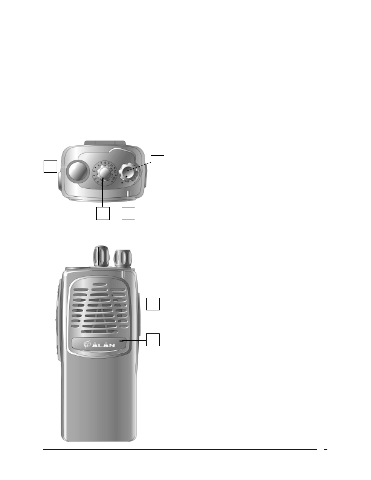
Top
Antenna connector.
[1]
1
2
connector ( M X t hread ty pe) .
Power ON/O FF knob.
[2]
transceiver on and off.
Channel selector knob.
[3]
the operative channel.
Fit the antenna to this
Rotate this knob to turn the
Rotate this knob to select
Status LED
[4]
43
current radio’s status.
. Glows in different colors to show the
Front
Speaker
[5]
5
6
emits the reception sound.
Microphone
[6]
microphone located in this place
. The built in speaker locat ed in this point
. Your voice is detected by the
Page. 6
Page 7
HP105/HP405 User manual
10
11
12
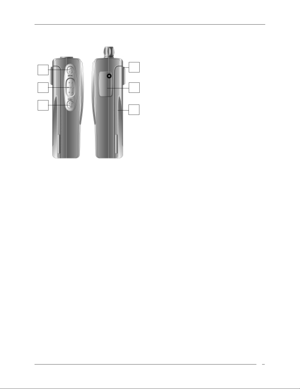
Side (left and right)
Microphone connector
[7]
9
7
8
speaker/microphone, headsets for VOX use and
other accessories. It must be protect ed with the
supplied rubber cap when not in use. For the
related pin connections please see to
“Microphone connection”.
Battery pack
[8]
energy to your radio.
Release
[9]
Allows to remove the battery pack
MON
[10]
[11]
[12]
(monitor ) butt on. Enables the loudspeaker
for audio monitoring of the tuned channel
PTT
(Push To Talk) button. When pressed
switches the transceiver from reception to
transmission
FUN
(Function) button. Enables VOX and Scan
Function. See VOX and Scan chapters.
. This NiMH battery pack supplies
button (located on the battery’s body).
. For remote
Page. 7
Page 8

HP105/HP405 User manual
Setup
Unpacking
The following items are in the package:
(a) Transceiver’s main body
(b) Rubber ducky antenna
(c) Bat t er y pac k NiMH 1,300 mA/H
(d) Belt clip
(e) User’s guide (this book!)
If something is missing please promptly advise your supplier.
Page. 8
Page 9

HP105/HP405 User manual
Fitting/removing the antenna
To fit the antenna:
1) Locate the antenna ter minal (thread MX connector) on transceiver’s top.
2) Hold the tr ansceiver with one hand and the base (the thicker par t ) of the antenna with the other one.
3) Attach the included rubber ducky antenna to the antenna terminal by turning it clockwise until it is firmly
locked. Don’t overt ight it.
To remove the antenna do the same described procedure. At step 3 turn the antenna base
counterclockwise.
"
Leave the antenna fitted on the radio. You can’t communicate without it. Moreover,
transmitti ng wi thout t he antenna may damage the TX output fi nal stage. For the same reason
use only the supplied antenna.
!
The supplied antenna is broadband type and covers the whole spectrum , so it doesn’t need any
ali gnm ent procedur e.
Instal ling/removi n g th e b attery p ack
To install the battery pack :
1
2
To remove the battery pack:
1
PUSH DOWN
2
SLIDE DOWN
PUSH DOWN
LIFT UP
1) Hold the transceiver’s body with one hand and the battery
pack with the other. Put the batter y pack onto t he bottom of
the transceiver.
2) Gently push the battery pack toward the transceiver’s back
edge.
3) At the end you will hear a c lic k : the ba ttery p a c k will snap into
place and should be firmly locked.
1) Press the battery release button located in the back of the
battery pack.
2) Keep the button pressed and gently pull the battery pack
away f rom the transceiver back edge ( the opposite operat ion
of the previous step 2) .
3) Remove the battery pack by separating it from the
transceiver’s body.
Page. 9
Page 10

HP105/HP405 User manual
Installing/removing the belt clip
The supplied belt allows you to hang the transceiver up to your belt or jacket when you are not using t he
radio and you are just in stand-by condition (ready to receive calls).
To fit the belt cl ip onto the transceiver’s body:
1
SLIDE DOWN
1) Just gently slide the clip into the appropriate
guides locat ed in the t ransc eiver’s back unt il it
firmly locks.
To remove the belt clip:
LIFT UP
2
PUSH
3
2) Press the belt clip spring;
3) Reverse t he over stated st ep 1.
Charging the battery pack
To charge the supplied battery pack you have to setup the standard charger and connect the radio as
follows:
1) Connect the jack coming from the AC adaptor to
the cradle’s socket.
2) Connect the AC plug of the AC adaptor’s power
cable into an earthed AC power outlet.
3) Ensure that the radio is switched off.
4) Insert the radio into the cradle with the keypad
toward you (the three metallic contacts of the
battery pack must touch with the three contacts
inside the cradle).
5) Wait 8-9 hours and remove the radio after that
time.
!
Don’t remove the radio before 8 hours,
otherwise the battery’s duty could be
temporari ly reduced.
"
Don’ t f or get t o r emove the radio af t er 9 hour s.
"
The batter y charger i s for i ndoor use only.
"
For the next charges, best duty and batt ery l i f e please fully see the chapter “Battery Packs”.
Page. 10
Page 11

HP105/HP405 User manual
Basic Operati ons
This section describes how the standard operations work. Standard operation can be changed by
programming, moreover the functions the radio includes can be modified via an IBM compatible PC. For
this reason the way y our radio operates may be upgraded and may slightly differ f rom w hat is described
here.
!
IMPORTANT: Due to the full programmability of the radio, certain commands could be
unavail able. In case of doubts please contact your deal er/radio network admi nistrator f or fur ther
details.
Switching the radio ON/OFF
To switch the radio on:
1) Rotate the PWR/VOL knob clockwise until the radio is sw itched on: the CPU will start an autotest
showing in sequence:
• LED w ill light GREEN, then RED and finally OFF.
• A beep confirms that the autotest is pass ed
!
The self - test goes very f ast, theref or e the LED could not be seen.
To switch the radio off just rotate the PWR/VOL knob anticlockwise.
Adjusting volume
The PWR/VOL knob is used to adjust the RX volume: just t urn it clockw ise to increase or anticlockwise to
reduce it.
Channel selection
If your radio has been programmed with more than one channel you can easily change it. To select a
channel, turn the channel selector knob clockwise or anticlockwise until the channel indicator on the knob
matches the wished channel.
Reception
Your radio could be previously programmed to work, channel by channel, in “Open traffic” or “GROUP
MODE (CTCSS/DCS)”. Please have a look to eac h description and ask your radio network manager or
dealer which mode your radio channels w or k.
• OPEN TRAFFIC: in this case you will hear any communication which will be transmitted on the
selec ted channel. When t he right c arrier is rec eived your squelch w ill unmute, y ou w ill see the st atus
LED glowing gree n and you w ill hear the message.
• GROUP MODE:
• CTCSS/DCS (Continuous Tone Code Squelch System - Digital Coded Squelch): they are systems
which use particular TX signalling (a continuous sub audio tone for CTCSS or a digital code for
DCS) as an access “key” to work a r epeater ( encoder) or t o unlock the party’s signalling se nsitive
squelch. This last condition allows to share more radio networks in the same frequency. In this
case you will rec eive only messages coming from parties sending a proper TX signalling. During
CTCSS/DCS operation the radio may be set-up so that the appropriate CTCSS/DCS decoder
Page. 11
Page 12

HP105/HP405 User manual
enables the speaker. Speaker w ill re main mut ed until the co rr ect CTCSS t one or t he cor re ct DCS
code is received. In case of unmuted speaker, the message will be hear d and t he sta tus LED w ill
glow amber. Units of t he same group are not affected by communication on the same channel with
wrong CTCSS/DCS.
"
CTCSS/DCS allow s to share more than one radio network i n t he same frequency, however t hey
are just useful t o avoid disturbing stations not owni ng of t he same networ k wit h messages not
related to them. In any case, if more than one station is transmitting at the same time, this will
cause an interference. Don’t transmit if the status LED is glowing. Wait till nobody is
transmitti ng on t he channel.
Monitor
Monitor button can enable / disable “GROUP MODE (CTCSS/DCS)”.
1) To enable GRO P M O DE. Press
2) To Disable GROUP MODE. Press
NOTE:
!
3) Press and Hold MON button: internal squelch is disabled and your speaker in unmuted. Every
environmental noise is heard.
if CTCSS/DCS tone is not programmed, GROUP MODE function is not available.
MON
button. A Sub Audible Tone mutes your speaker.
MON
button. You are work ing in “O pen Traff ic” .
Transmission
When you need to t r ansmit please get used to follow all these steps:
1) Ensure that the channel is not busy (otherwise you will create an interference, please wait till that
condition).
2) Press the
3) Start talking at a normal voi ce l evel at appr oximately 10 cm fr om the microphone (keep the
pressed).
4) When your message is over, r elease t he
!
Don’t shout! It won’t increase the distance range, but rather will make you heard di s torted.
!
Don’t release the PTT bef ore your message i s over or start talking bef ore pressing i t, otherwise
your message will be “chopped”.
!
A handheld radio doesn’t normal ly al low to talk and recei ve sim ultaneously , for this reason m ake
your messages with a r easonable time. When y ou are talking the other parties can’t do that, so
don’t occupy too much the channel. Use the common sens e.
!
The radio might be programmed with a timeout timer which automatically put your radio in
reception i f you talk too muc h (after a pr eset time). In this cas e r elease the PTT and wait f or few
seconds: the radi o TX f eatures will be automatically restored. Ask the network responsible or your
dealer f or further details .
PTT
key: the status LE D will glow red.
PTT
PTT
key
!
The radio might be programmed with a busy channel lock out which automatically disables
transmis sion if your channel is busy.
Page. 12
Page 13

HP105/HP405 User manual
Transmission P o wer
Your HP105/HP405 can transmit w ith two power levels accor ding to the distance of your par ty stat ion(s).
This option is programmed via PC and it can not modified by the user. We do recommend, when possible,
to use the Low powe r: it will increase the batt ery d uty and will red uce t he risk t o make inter fer ence with
sta ti ons not owning to yo ur radio net wor k whic h m ay sha ring t he s ame channel with you.
!
If the low battery mark is "blinking" (Low Battery indication), the Unit will then automatically revert
to Low RF Power when transmi tting i n order to help prol ong the Battery's operati onal lif e. In this
case, two short beeps will be heard before transmi ssion.
Scanning channels
If you have more than one channel progr ammed, your HP105/HP405 can scan them: in other words it can
cycle through them and stop when a signal is detected.
The advanced scan functions of the radio allow to optionally look for car rier or carrier w ith CTCSS/DCS or
CTCSS.
1) To activate the scan Switch Off and then Switch O N th e r a d io holdin g MON an d F UNC bu tton s .
2) A long beep will be hear d when enter t he SCAN MO DE .
3) During scanning the LED will b link amb er.
4) Only t he channel in the Scan List will be monito r e d for a c tivity. The Sc an Lis t is pr og rammed via PC.
5) During scanning the channel selector knob becomes invalid.
6) To stop channel scan Switch Off and then Switch O N the radi o hol ding MON and FUNC butto ns .
7) One among the programmed channels can be assigned as Priorit y Channel. The scanning will look
back at t he priority channel with high frequency.
8) User can select the priority channel:
9) To select Pr iorit y channel, befor e st arting the Scan Mode (befor e switching On the radio) s elect the
channel using the selector knob.
NOTE
!
On th e ra dio hol di ng M ON + FUNC and r adio will not start the Scan Mode. At least two channels
must be in the Scan List for the Unit to be put in the SCAN Mode.
!
become audible. When the activity on that channel ceases, the unit will automatically resume
scanning.
!
carri er has the appropr i ate si gnalling.
!
activity, the Unit will automatically resume scanning.
: If the Scan List has no channel s, a low tone (error beep) will be heard when you switch
When a proper signal is received on a channel, the radio will stop scanning and audio will
If CTCSS/DCS have been previously programmed, the scanning will stop only if the received
If PTT is pres sed dur ing scanning, the r adi o will transmit on the first vacant channel. In case of no
Advanced Operations
In this se c tion we’ll d es c ribe so me a dvanced oper at ion which you can do wit h your handheld tr ansceiver:
Page. 13
Page 14

HP105/HP405 User manual
Handsfree transmissio n (VOX)
VOX (Voice Operated eXchange) is an automatic system which allows you to automatically switch the
transmission in hands free mode just by speaking in the built- in microphone of an headset (not provided
with the unit). Please ensure t hat the handset is suitable for your transceiver as reported in the paragraph
“Microphone connection”. To insert the VOX and adjust sensitivity:
1) Sw it ch on the radio keeping pressed the
2) Connect the optional headset with built-in microphone to the microphone connector located on the
transceiver’s side.
10) Ensure that the headset’s built-in microphone is located close to t he side of your mouth.
11) Hold the
versa. Adjust the VOX sensitivity in order t o ensure a stable transmission when speaking with a normal
voice level.
"
We recommend to set the just minimum sensit ivity as possible. A too high value could cause
accidental transmissions, especial ly in hi- noise environments.
!
FUNC
PTT button i s disabled during VO X.
key for more t han 2 seconds to t oggle VOX sensitivity from HIGH to LOW and vice
FUNC
key.
Page. 14
Page 15

HP105/HP405 User manual
Care and Maintenance
Battery Packs
Information on rechargeable batteries
• When the battery pack is new it doesn’t provide 100% of its efficiency; it means that it might be
discharged earlier. To r each the full battery life you have to “r un-in” the batter y with at least 3-4
deep charging/discharging cycles, after that it will reach its maximum capacity. Please see
“Properly charge of battery packs” for further det ails.
• Should you properly use the batt ery pack, you will obt ain at lea st 400 c harging/d ischar ging cycles
(300 wit h the optional rapid charger). The battery duty will pr ogr ess ively re duce af ter 2/ 3 of it s life
(approx.).
• Rechargeable battery packs lose their charge with the time if left unus ed (s elf di sc har ge) ; thi s is
normal. A NiMH (Nickel Metal Hydrat e) batt ery can reduce 10 to 20% of its stor ed energy in few
days.
Properly charge of battery packs
1) Ensure that the radio is switched off,.
2) I nsert t he radio into the cradle as explained in the paragraph “Charging the battery pack”
3) W ait the neces sar y t ime to provide a full char ge. If the pa ck is n’t comple tely dischar ged y ou will need
less than 8 hours.
"
Don’t overcharge the battery: always remember to remove the radio after the necessary time.
"
The batter y charger i s for i ndoor use only.
!
When possible, charge the battery when it is full y dischar ged or, at l east, you have used it f or the
major part of i ts duty; otherwise the battery’s duty coul d be tempor arily reduced. Please see the
paragraph “ M em or y ef fect”.
!
Don’t remove the radio before the necessary time, otherwise the battery’s duty could be
temporari ly reduced. Pl ease s ee the paragr aph “ M em or y effect”.
Memory effect
The supplied NiMH (Nickel Metal Hydrate) bat tery pack is made with a more advanced t echnology than
normal NiCd (Nickel Cadmium) battery. For t his reason it is virtually free of what is c alled “ memory ef f ec t ” ,
which aff ects NiCd batteries. M emory effect is a temporary capacit y r eduction which reduces the bat ter y
duty. Memory effect may occur just if you regularly charge the battery w hen you haven’t discharged it at
least at 50- 70%. Memory eff ect c an be easily avoided by following these simple rules:
Page. 15
Page 16

HP105/HP405 User manual
• When possible charge battery packs only when they are completely discharged, i.e. when the
batter y icon has no bars inside.
• Don’t remove the battery f r om the charger befor e t he necessary time to provide a full charge.
• Provide at least two deep charge/discharge cycles per month.
• The best way to avoid memory eff ect is to use two battery packs and alternate their use with the
rad io. This will a llo w you to k eep on your transceiver’s operation by replacing the battery pac k just
when it’s fully discharged and use the spare (charged) one. At the end of your wor k ing day y ou w ill
charge the discharged pack f or 8 hours.
Erasing memory effect
Memory effect can be easily erased just by applying 3-4 deeper charge/discharge cycles:
1) Use the battery fitted in the radio and wait till the radio swi tches of f .
2) Wait at le as t one hour and then tr y to sw itch on the rad io: you will not e that some energy has rest o red
in the batt er y, because the radio can be switched on.
3) Leave the radio in RX until the radio switches off again.
4) Repeat st eps 2) and 3) t hree times.
5) Fully char ge the batt ery f or 9 hours and chec k the bat tery dut y. If some memor y eff ect s till exist go
back to st ep 1.
!
If the battery duty doesn’t improve after three of the over stated cycles, it means that your battery
pack is f aulty or has r eached the end of li fe ( please see “Inf ormation on rechar geable batteries”) .
In this case please ask y our deal er to prov i de a new battery pack.
Warnings for battery and chargers use
Please use these cautions to avoid damaging battery packs or the transceiver:
"
Before using the bat t er y charger careful ly read any rel at ed warning or cauti on.
"
Don’ t short bat t er y t e r minal s: this may cause fi r e, burns or explosions.
"
Never dispose batter ies into fir e they may explode causing fi re, burns or explosions. Str ictly
foll ow any disposal regulati on of your Count r y.
"
Use only genuine batteries and chargers. The use of non genuine accessories may cause
burns, fir e or explosions; making serious damages to the radi o/battery or serious inj uries to
people.
"
Battery chargers are for indoor use only.
"
Be certain that your power source matches the rating l isted for the suppli ed batt ery charger
(AC Adaptor). If you are not sure, check with your dealer or with your local power company.
"
To avoid damaging the power cable of t he bat tery charger, do not put anything on i t or place i t
where it will be walked on. Insert the plug in socket provided with earth connection.
"
Avoid str ong shocks. D on’t use the charger if it received a str ong shock, has fall en down or i t
appears damaged; immediately contact an authorized service stat i on.
Page. 16
Page 17

HP105/HP405 User manual
"
Never try to disassemble or service the charger by your self. Always contact your local dealer
f or assistance.
"
To reduce the risk of electric shocks disconnect the plug before providing any cleaning or
maintenance. Grasp the pl ug (not the cable) to r emove the plug fr om the socket. The use of
non suitable ext ension can cause fir e or el ectri c shocks.
"
Don’t expose batteri es directly to temperat ures below -20° C or greater t han 35°C duri ng t heir
use and don’t charge them outside the range of + 5 t o + 55° C.
Radio maintenance
Cleaning battery packs
Wipe the battery c ontacts with a clean and lint free cloth to r emove dirt, greas e or any other material which
may prevent a good electr ical contact. I f contacts are very dirty y ou can also wipe them using a sof t pencil
rubber (not hard erasers for ink!). If you feel that battery contacts aren’t still working properly, please
contact your authorized dealer.
"
Do not use li qui d, alcohol or aerosol cleaners.
Cleaning the radio
• Wipe the radio wit h a clean and lint free cloth to remove dust. If it is very dir ty, you can use a damp
(slightly moistened with water) cloth.
"
Do not use li qui d, alcohol or aerosol cleaners.
!
If you normally use your radio in dusty or hard environments, we do recommend to use the
optional car r ying case. Please s ee “ O pti onal acc essor ies”.
Connectors
When the connectors ar e not being used, t hey should be fitt ed with the supplied cover caps.
"
Only suit abl e accessories must be connected t o t he r el ated connectors.
Page. 17
Page 18

HP105/HP405 User manual
Optional accesso ries
These optional accessories can be used to improve the transceiver’s performances:
• Spar e batt ery pa ck. I t extends t he duty time a nd minimizes the possibilit y of memor y ef fect (p lease
see “Memory effect”).
• Rapid charger. It r echarges the battery packs in 1 hour and provides trickle charge w hen they reached
their full charge.
• Carrying case. It protects your radio against small shocks and scratches; the best for use in hard
environments.
Microphone connector
The microphone connector is designed for the connection of two basic accessories (not supplied as
standard):
• An external speaker /m icrophone, which allows t o use the radio firmly secured to your belt by means
of the supplied belt clip.
• An headset with built-i n mi crophone, which additionally add the VOX facility , in other w ords you can
switch the transmission just by talking at the headset’s microphone in hands free convenience. For
further details please see “Hands fr ee t r ansmission (VOX)” .
Any kind of accessory for the above stated purposes can be connected to the microphone connector,
provided that they meet t he following requirements:
• Jack connector s for Speaker (SPK) and Micro phone (M I C) must be res pe c t ively standard t y pe 3,5 mm
and 2,5 mm. and connected as f ollows:
MicGND
MIC
SPK
Spk GND
• The suggested speaker input impedance is 8 Ohms
• The microphone should be condenser low-impedance ty pe.
• Any accessory should be hi-quality suitable for profess ional use.
"
Please don’t connect any accessory which you are not sure meet the above stated
requir ements. You could create serious damages to your r adio. In case of doubt pl ease contact
your authorized dealer.
Page. 18
Page 19

HP105/HP405 User manual
Quick reference
Operation resu me
Should you are now familiar w ith your t ransceiver you do know now that it’s very eas y to use one of its
function, you just have to do what follows:
1) Press the
2) Pr ess and Hold
3) Press the
4) Before entering the SCAN MODE, use the channel selector knob to select the priority channel.
5) Hold the
6) W hen VOX function is enabled, Press the
"
Press the MON key and switch on the unit. The unit enter s the PROGRA MM ING M ODE. This
operati on is only allow ed t o aut hor ized person.
MON
to enable/disable GROUP MO DE.
MON
MON + FUN
FUNC
key and switch on the radio to enable/disable VOX.
button to enable/disable the squelch.
keys at the switching ON to enter the SCAN.
FUNC
to set HIGH or LOW VOX sensitivity.
Page. 19
Page 20

HP105/HP405 User manual
Index
A
Adjusting
Volume 11
Antenna
fitting/removing 9
B
Battery charger
rapid (optional) 18
standard 10
Battery pack
Charging 10
Battery packs
cleaning 17
Erasing memory effect 16
Information on rechargeable batteries 15
Memory effect 15
Proper changing 15
Warnings for battery and chargers use 16
Belt clip 10
C
Care and Maintenance 15
Carrying case 18
Channel selection 11
Charger
Cleaning the radio 17
Connectors 17
Conventions and Symbols 5
H
Handsfree transmission (VOX) 14
M
Memory effect 15
Microphone connector
O
Optional accessories 18
Carrying case 18
Rapid charger 18
Spare battery pack 18
Output power 13
P
Part Names and their functions 6
Power
button 11
ON/OFF 11
TX output 13
Vedi
Battery charger
18
Q
Quick reference 19
Operation resume 19
Page. 20
Page 21

HP105/HP405 User manual
R
Radio maintenance 17
Rapid charger 18
Reception 11; 12
S
Safety 3
Scanning channels 13
Setup
Battery pack 9
Belt clip 10
Charging the battery pack 10
Fitting antenna 9
Package contents 8
Unpacking 8
Switching the radio ON/OFF 11
T
Transmission 12
Transmission Power 13
Transmission Power 13
V
VOX 14
W
Warning notes 3
Warnings for battery and chargers use 16
Page. 21
 Loading...