

Page 1

OPERATOR'S MANUAL
BASE TECH II BASE/REPEATER STATION
8/01
Midland R adio Corp.
Page 2

Base Tech II Base/Repeater Station Operator’s Manual
Introduction..................................................................................................................................................3
Description..............................................................................................................................................3
Features..................................................................................................................................................3
Controls, Indicators and Connectors ......................................................................................................4
Operation......................................................................................................................................................7
Installation and Programming .................................................................................................................7
Basic Operation.......................................................................................................................................8
Front Panel Operation.............................................................................................................................9
Signaling...............................................................................................................................................11
Scanning ...............................................................................................................................................14
Locking the Keypad ..............................................................................................................................17
Changing Tone Signaling Systems.......................................................................................................17
Displaying the Channel Information......................................................................................................18
Display of Received Tone Frequencies. ...............................................................................................18
Bar Graph Displays...............................................................................................................................19
LCD Display Back Light........................................................................................................................19
Transmit Power Change .......................................................................................................................20
Calling Party ID Displa y ........................................................................................................................20
Displaying any Radio's ID Number .......................................................................................................21
Emergency Caller Display.....................................................................................................................21
Automatic Transmit in Repeater Mode .................................................................................................22
TX Test Mode........................................................................................................................................22
Keypad Test Mode ................................................................................................................................22
Frequency Band Test Mode..................................................................................................................24
Starting Message..................................................................................................................................24
Serial Number Display ..........................................................................................................................25
EEROM Data Check Mode...................................................................................................................25
Hardware Error Detection.....................................................................................................................25
RS232C Communications Error............................................................................................................26
2
Page 3
Page 4
Base Tech II Base/Repeater Station Operator’s Manual
The Base Tech II Base Repeater includes 5-tone se lective calling encoder/decod er with non-predictive
decoder, as well as a DTMF encoder and voice encr yption option. It supports bot h all channel scanni ng
and programmed channel scanning for base use.
The Base Tech II Base Repeater is fitted with a large full dot matrix LCD that is used to display the
channel numbers and nam es, frequenc y and tone progr ammed inf ormation and sign aling inf ormation. All
user-interface keys and knobs are conveniently located on the front of the radio. All user-entered
functions are easily activated in a log ic al m anner via the ke ypad.
The Base Tech II Base Repeater is supplied with a n "N" type connector for the tr ansmitter, and a BNC
connector for the receiver to allow easy connection to the duplexer or feeder cables.
The rear panel incl udes a 9-way D-sub connector f or the attachment of an external shar ed tone panel.
Also included is a 25-way D-sub connector that enables external interface to other radios or control
equipment.
The Base Tech II Base Repeater is supplied complete with the following items:
o Base Tech II Base Repeater
o DC Cable Connector
o Operators Manual
o Hand Microphone
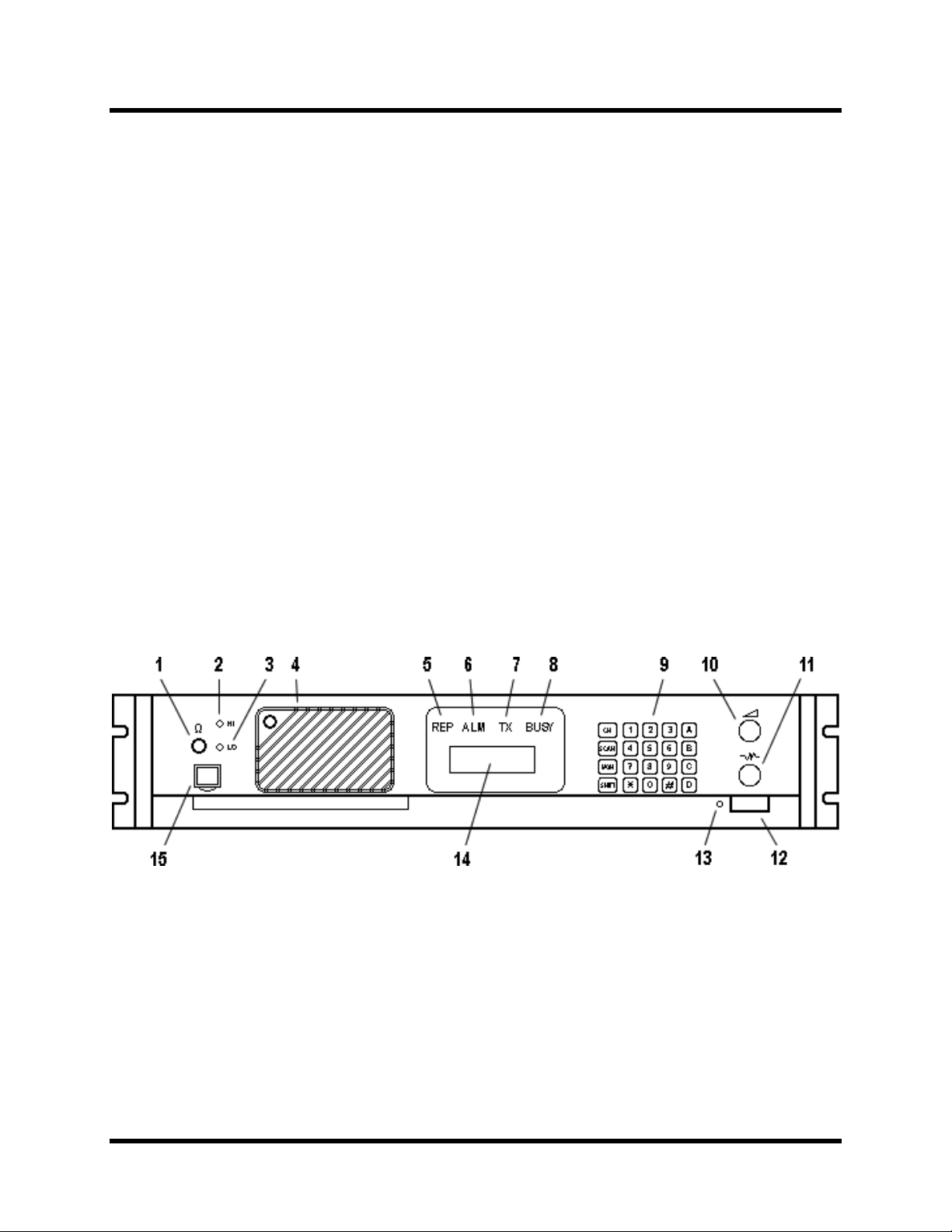
Controls, Indicators and Connectors
Front Panel Controls
•
1. Headphone Socket
This socket is pr ovided to allow users to listen to the Base Tech II Base Repeater us ing headphones.
Plugging a headphone into this socket will disconnect the built-In speaker. It does NOT include a
microphone input or TX PTT facility.
2. High TX Power
This is a service point and is not used by the radio operators
4
Page 5

Base Tech II Base/Repeater Station Operator’s Manual
3. Low TX Power
This is a service point and is not used by the radio operators
4. Loud Speaker*
The receiver audio s ignals are he ard from this speaker (provided that the volum e setting is loud enough
and provided that the speaker has not been muted by one of the tone signaling formats).
5. Repeater Mode Indicator LED
The Repeater Mode Indicator LED will il luminate "REP" in
programmed for Repeater operat ion. This LED is NOT illum inated on an y channel that is programm ed to
operate in Base mode.
6. Alarm Mode Indicator LED
The Alarm Mode Indicator LED will illuminate (Flashing) "ALM" in
detects a fault in the receiver module, the transmitter module, or the PA module on the selected channel.
7. Transmit Mode Indicator LED
The Transmit Mode Indicator LED will illum inate "TX" in
transmitting.
8. Busy Mode Indicator LED
The Busy Mode Indicat or LED will i lluminate "BUSY" in
receives a carrier signal on the selected channel that is greater than the Squelch setting.
9. Keypad*
The 5 x 4 key Ke ypad is used to enter c hannel select ion, tone inf ormation, and other data into th e Base
Tech II Base Repeater. Specific key sequences are described fully in section 4 of this document. It
includes the following keys: CH, SCAN, MON, SHIFT, 1, 2, 3, 4, 5, 6, 7, 8, 9, 0, •, #, A, B, C, and D.
10. Volume Control*
yellow
red
whenever the Base Tech II Base Repeater is
green
when the selected c hannel has been
orange
whenever the Base Tech II Base Repeater
whenever the transceiver
The Volume Control is used to set the audio output level from the loudspeaker. Rotate this knob clockwise
to increase the audio level, or counter-clockwise to reduce the audio level.
11. Squelch Control*
The Squelch Contro l is used to set the squelch threshold. Select a channel that is not being used and
slowly rotate this knob clockwise until the annoying background noise ceases. It may be desirable to
rotate this knob clockwise, slightly past the squelch threshold, to compensate for varying background
noise levels.
12. Power ON/OFF Switch
The Power ON/OFF Switch is use d to switch the Base Tech II Base R epeater "ON" or "OFF". Pr ess this
knob to switch the Bas e Tech II Base Repeater "O N". Press this knob again to switch the Base Tech II
Base Repeater "OFF". This knob is slightly more depressed when in the "ON" position.
13. Power On Indicator LED
The Power ON Ind icator LED will illum inate in
green
whenever the Pow er ON/OFF switc h is in the "O N"
5
Page 6
Base Tech II Base/Repeater Station Operator’s Manual
position.
14. Liquid Crystal Display (LCD) (not used on Single Channel Models)
The LCD comprises of four (4) lines each of whic h is capable of displa ying twenty-one (21) characters.
The first line, und er norm al oper ating c ondit ions , dis plays th e str ength of the sig nal being r eceive d o n th e
selected channel as a bar graph. T he sec ond line d ispla ys the s trength of the trans m itting po wer as a bar
graph. The third line dis p lays the selected chann el number (up to four c har ac ter s) in t he f ir s t f ive lef t ha nd
character spaces, and displays the channel name (up to eight characters) in the next eight character
spaces.
Any combination of the following characters may be used in the channel name:
0-9, A-Z, a-z, / + - * # ! $ % ( ) = [ ] < > ? and space
This area of the LCD is left blank when channel names are not used.
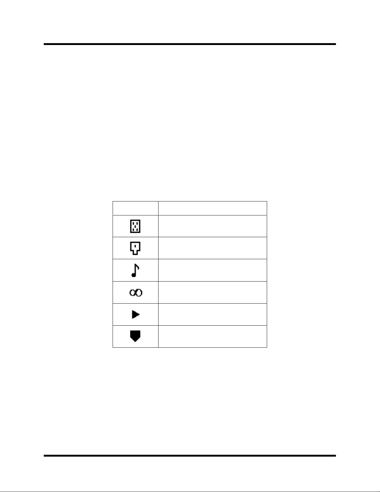
The six character spaces on the right hand side of this line are used to display status symbols as follows:
Symbol Status
The monitor status.
The key lock status.
The tone encode status.
The scan mode status.
The high power transmit status.
[SHIFT] key is depressed.
On the left hand side of the fourth line, the type of tone signaling system selected by the user is
displayed. For example, "5TON" indicates 5 Tone signaling while “DTMF” indicates Dual Tone Multi
Frequency signaling.
The right hand side of the fourth line is used to display data that the us er enters (for example, 5 Tone
calling sequences) . These charac ter spaces ar e also used b y the Base Tech II Base Repeater to displa y
messages and information directed to the user.
15. Microphone Input Socket
Connect the microphone into this socket.
6
Page 7
Base Tech II Base/Repeater Station Operator’s Manual
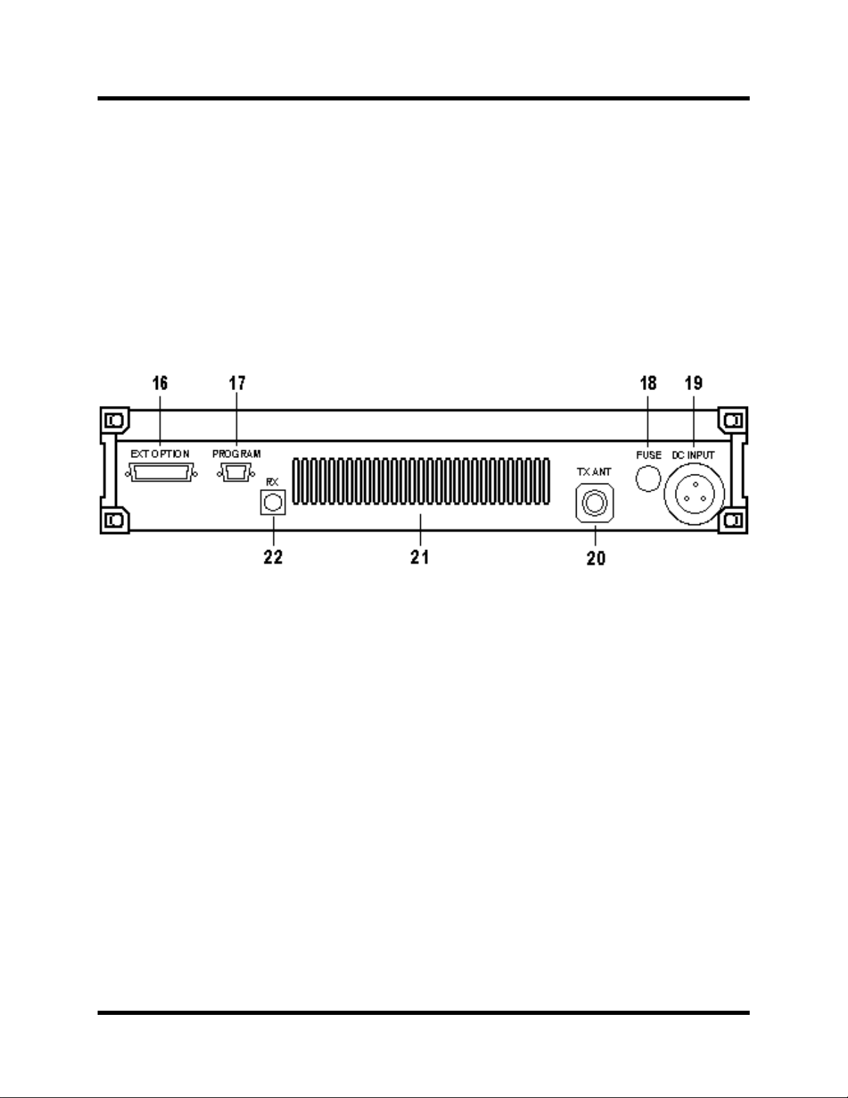
Rear Panel Connectors
•
16. 25 way External Options Connector
17. 9 way Programming Connector
18. DC Input Fuse Holder
19. 3 way DC Input Socket
20. TX/Antenna Connector (N type)
21. Ventilation Slots
22. RX Connector (BNC type)
OPERATION
Installation and Programming
As the Base Tech II Base Repeater can be installed to opera te as either a Bas e St ation or as a R epeater,
some of the instructions in this docum ent may apply to one application only, some may apply in both
cases, while others may only appl y if the partic ular func tion has been enab led during programm ing of the
Base Tech II Base Repeater.
The Base Tech II Base Repeater must be programm ed before it will operate correctly. This should be
done by the equipm ent supplier or a qualif ied radio tradesman. T hey will require the Base Tech II Base
Repeater programming software to do this correctly.
7
Page 8

Base Tech II Base/Repeater Station Operator’s Manual
It is important that the Base Tech II Base Repeater be correctly installed at its working location by a
qualified radio technician.
As a minimum, it is necessary to:
o Connect the DC Input power l ead to a suitable 13.8 Volt Regulated DC Power suppl y that has
sufficient capacity. (Ensure that the DC Polarity is correct).
o Connect the two antenna connectors to suitable antennas (ensure that the VSWR of the
antennas is correct).
o Insert the microphone into the microphone connector on the front panel.
Basic Operation
Switch On
•
Switch the Base Tech II Base Repeater "ON" by pressing the knob (12). Then check that the LED
indicator (13) is illuminated.
Adjust the Volume Setting
•
Rotate the Volume Knob (10) clockwise (from the fully counterclockwise position) until the audio level
from the speaker is suitable.
Adjust the Squelch Setting
•
Rotate the Squelch Knob clock wise (f rom the fu lly count er cloc kwise posit ion) slo wly unt il th e back ground
noise can no longer be hear d. It is wise to r ot ate the knob slightly further in t he clockwise direc ti on so that
variations in the background no ise level do not "break" the sq uelch setting and cause a nnoying squelch
noises to be heard from the speaker.
Select the Channel
•
Select the require d channel by pressing the C H key followed by the c hannel number k ey. The channel
number keys must be s el ec ted wit hin t wo seconds. For exam ple, [CH] + [0] + [1] to selec t C ha nne l 1. The
LCD Display should now display CH01 and (if programmed with a channel label) the channel name:
"CH01 NAME".
Receiving
•
You should now be able t o hear any radio traffic that occurs on cha nnel #1 on the Base Tech II Base
Repeater. It may be necessary to adjust the Volume setting to suit your listening requirements.
Transmitting
•
Depending on the legal requirements in your country, and the operating requirements within your
organization, it may be necessar y to announce your Call Sign. In addit ion, it will pr obabl y be ne cess ary to
announce the Call Sign of the party you are calling at the start of your transmission.
When transmitting, it is necessary to hold the microphon e about 3 inches from your m outh and speak
clearly into the front of the microphone.
It is also necessar y to press and hold the “Press To Talk” (PTT) bar on the side of the microphone while
speaking into the microphone.
8
Page 9

Base Tech II Base/Repeater Station Operator’s Manual
Front Panel Operation
This section desc ribes m os t signaling an d other a dvanc ed f eatur es th at ar e avai lable on the Base Tech II
Base Repeater. The availability of s ome features is depend ent on t he progr am ming of the transceiver an d
installed options . You may find it worthwhile to dis cuss these f eatures in det ail with your radio sup plier to
obtain a full understanding of their benefits.
Keypad Operation
•
The Keypad is the inter f ac e be t ween th e us er and the B ase Tech II Base Repeater. It is used to enable or
disable various functions and to enter the required data for signaling purposes.
The word (5-Tone) or (DTMF) shown after the described feature indicates that the described feature
applies to the particular signaling format.
The following keys are used for the purposes described:
[0] - [9] Entering new channel numbers
Entering the "KILL" password
Entering signaling encoding numbers (5-Tone) (DTMF)
Entering DTMF numbers (DTMF)
[A] Advancing the Base Tech II Base Repeater to the next higher channel
Entering the signaling "A" tone (5-Tone) (DTMF)
Encodes the "A" Tone (DTMF)
[B] Advancing the Base Tech II Base Repeater to the next lower channel
Entering the signaling "B" tone (5-Tone) (DTMF)
Encodes the "B" Tone (DTMF)
[C] Entering the signaling "C" tone (5-Tone) (DTMF)
Encodes the "C" Tone (DTMF)
[D] Entering the signaling "D" tone (5-Tone) (DTMF)
Encodes the "D" Tone (DTMF)
[•] Displays the previously entered encode numbers (5-Tone) (DTMF)
Encodes the "•" -Tone (DTMF)
[#] Encodes the signaling numbers that are displayed in the LCD display (5-Tone) (DTMF)
Encodes the "#"-Tone (DTMF)
[CH] Used with two channel numbers [0] - [9] to change the active channel on the Base
Tech II Base Repeater. E.g. [CH]+[9]+[0] will chang e the active channel to Cha nnel 9 0
(provided Ch 90 has been programmed into the Base Tech II Base Repeater.
[SCN] Used to place the Base Tech II Base Repeater into the "All-Scan" mode where the
Base Tech II Base Repea ter will scan all programm ed channels. Pressing the [SCN]
key again will cause the Base Tech II Base Repeater to exit from the "All-Scan" mode.
[MON] Switches the Base Tech II Base Repeater between "Mon itor ON" mode and "Monitor
OFF" mode and is used to "Un-mute" the radio when using selective calling
(depending on the programming of the Base Tech II Base Repeater).
9
Page 10

Base Tech II Base/Repeater Station Operator’s Manual
Keypad Operation using the [SHIFT] Key
•
Some of the Base Tech II Base Repeater's features and r elated functions can be changed by us ing the
[SHIFT] key. To make these changes, it is necess ary to first press the [SHIFT] k ey followed by the other
keys within a two second timeframe.
The following key sequences are used for the purposes described:
[SHIFT]+[0] Toggles the tone system between 5-T one signaling and DTMF signaling
[SHIFT]+[1] Switches the LCD back-light to the ON or OFF position
[SHIFT]+[2] Toggles the transmitting power between High po wer and Low power
[SHIFT]+[3] Invalid Key
[SHIFT]+[4] Toggles between "Single Tone Encoding" mode and "5-Tone" or "DTMF"
signaling mode
[SHIFT]+[5] Invalid Key
[SHIFT]+[6] Enters the KILL mode to allow entry of the KILL password
[SHIFT]+[7] Displays the program m ed inform ation for the s elected (activ e) chan nel in the
LCD display
[SHIFT]+[8] Locks or Unlocks the Base Tech II Base Repeater's Keypad
[SHIFT]+[9] Toggles the Base Tech II Base Repeater between "Normal Channel
Scanning" mode and "Priority Channel Scanning" mode
[SHIFT]+[A] Restores a channel to th e Chann el Scanni ng List. (T he user m ust first select
the channel to be restored as the active channel)
[SHIFT]+[B] Invalid Key
[SHIFT]+[C] Indica tes to the Base Tech II Base Repeater t hat you have entered the l ast
number of a DTMF encoding sequence
[SHIFT]+[D] Invalid Key
[SHIFT]+[•] Deletes the active channel from the Channel Scanning List
[SHIFT]+[#] Will attach the "R-Num ber" data to the active encode number and transmit
the whole sequence
[SHIFT]+[CH] Will start or stop the display of the TX and RX bar graphs in the LCD display
[SHIFT]+[SCN] Will place the Bas e Tech II Base Repeater in the Progr am Scan m ode or ex it
from the Program Scan mode
[SHIFT]+[MON] Invalid Key
10
Page 11

Base Tech II Base/Repeater Station Operator’s Manual
Changing Channels
•
To change to another chann el, sim ply press th e [CH] k ey followed b y the num ber of the req uired cha nnel
within two seconds.
For example: To select Channel 8, press [CH] [0] [8]
To select Channel 99, press [CH] [9] [9]
Note that it is always necessary to enter two digits for the Channel Number. The channel # location
displayed in the LCD will become blank as soon as the [CH] key is pressed. T he cursor will blink at the
location of the channel number, and display the new numbers as they are entered.
It is also possible to ch ange cha nnels b y using the [ CH], [A] and [B] k eys inste ad of entering the channel
numbers. Pressing the[CH] then the [A] key will advance the channel to the next higher programmed
channel, while pressing [B] will ad vance th e channe l to the next lo wer pr ogram med channel.
Note that this action will ignore channels that have not been programmed into the Base Tech II Base
Repeater. Accordingly, the LCD display may appear to advance more than one channel if the missed
channel is not programmed into the Base Tech II Base Repeater.
Signaling
The Base Tech II Base Repeater includes some very sophisticated sig nalin g c ap abil i ties . W e suggest that
you have your radio supplier conduct some training on the use of these capabilities prior to using them.
While it is possi ble to use these sig naling capabiliti es in both repeater mode, and in bas e station m ode,
many will only be useful in practice when the Base Tech II Base Repeater is used in base station
configuration.
The Base Tech II Base Repeater supports the 5-Tone sequential, and/or the DTMF, and the Single Tone
signaling formats. The required signaling format(s) must be enabled when the Base Tech II Base
Repeater is programmed.
5-Tone Signaling
•
Available Tones
5-Tone signaling is comm only referred t o as “Selective Calling” (or Selc all) and usually comprises of a
series of 5 tones sequentiall y trans mitted or received in acc or da nc e with cer ta in inte r nat io nal standards. It
is possible to use longer sequences to enhance the signaling capabilities and to provide additional
functions.
Accordingly, the Base Tech II Base Repeater will enco de up to six teen (16) t ones and decode up to eight
(8) tones.
These tones can be any of the following letter/number combinations:
[0] - [9], and [A] - [D]
The most recently entered tone can be recalled and deleted by pressing the [•] key repeatedly.
Entering a 5-Tone Encode Sequence
When switched "ON", the Base Tech II Base Repeater carries out i ts self -test routine, then waits read y to
11
Page 12

Base Tech II Base/Repeater Station Operator’s Manual
accept 5-Tone encode num bers. Accordingly, it is necessary to ent er the required 5-Tone digits directly
using the keypad, then pressing th e [#] k ey to transm it the 5-Tone sequence. (Up to sixteen digits c an be
entered).
If it is necessary to enter the "R" num ber sequence to activate the repeater, the [SHIFT] key must be
pressed before pressing the [#] key.
If a 5-Tone number is NO T displa yed in the LCD, and the [#] ke y is pressed, the n the Base Tech II Base
Repeater will recall the most recent 5-Tone number and transmit it.
Recalling the last encoded sequence
Pressing the [•] will recall the m os t rec ent 5-Tone encode sequence and displ a y the sequ enc e in t he LCD
display. Continuing to press the [•] key will delete t he last digit of the s equenc e unt il al l digits are del eted.
In practice, users will usually delete the last one or two digits before entering the new digits.
DTMF Signaling
•
Available Tones
The following DTMF tones can be used in any number/letter combination:
[0] - [9], [A] - [D], [•], and [#]
NOTE: Tone [B] is NOT av ai lab le if the "Attach Decode No " f iel d i n th e DT MF Enc od e Menu has bee n s et
to "ON".
Up to sixteen (16) DTMF digits can be encoded in one calling sequence.
DTMF Tone Entry
There are two methods of en tering DT MF to nes. T he spec ific to ne enc oding for m at is selec ted dur ing the
programming of the Base Tech II Base Repeater in the <Main Menu><Encode Set><DTMF
Encode><Attach Decode No.> field.
Attach Decode No. "OFF" format
Pressing the PTT lever first autom atically selects the DTMF encoding for mat and allows direct entry of
DTMF tones.
Hold the PTT lever on the microphone while pressing the required DTMF tones. The tones will be
transmitted as the keys are being pressed.
Attach Decode No. "ON" format
Attach Decode No. "ON" automatically encodes the user’s DTMF decode number after the encode
number. This can be used for any purpose.
Enter the required DT MF tones (up to sixteen tones, except "B" tone) and then transmit the total t one
sequence (including the users decode number) by pressing the [#] key. All tones will be transmitted in one
continuous sequence after pressing the [#] key.
Pressing the [•] key will delete the last number entered.
Always confirm that the LCD is cle ar before proceedin g, as it may take up to 5 seconds for the t ones to
be sent.
12
Page 13

Base Tech II Base/Repeater Station Operator’s Manual
For example, assum e that your decode number is 12345, and that you wish to enc ode number 12346.
You will input 12346, and then press the [#] key. The Base Tech II Base Repeater will encode
"12346B12345". The c alled ra dio will disp la y “12345” in their LCD indic ating the ca lling par ty's num ber is
"12345".
NOTE:
DTMF tone.
Pressing the [SHIFT] k ey and then the [#] will encode ONLY the encode number (and not the decode
number).
Redialing with DTMF
If, during the programm ing of the Base Tech II Base Repeater, the <Attach Deco de No> field has been
set to "OFF", the redialing function operates as follows:
Press [SHIFT], then press [#] and the Base Tech II Base Repeater will redial the last encoded DTMF
number.
If, during the programm ing of the Base Tech II Base Repeater, the <Attach Deco de No> field has been
set to "ON", the redialling function operates as follows:
Press [#] and the Base Tech II Base Repeater will redial th e last encoded DTMF num ber with the Base
Tech II Base Repeater's programmed decode number.
Press [SHIFT], then press [#] and the Base Tech II Base Repeater will redial the last encoded DTMF
number without the Base Tech II Base Repeater's programmed decode number.
Restoring the last DTMF number to the LCD Display
It is possible to rest ore the las t encode d DTMF num ber to the LCD displa y, provided the <Attach Dec ode
No> field has been set to "ON" during the program ming of the Bas e Tech II Base Repeater. First, confirm
that the LCD is NOT displaying a ny DTMF numbers . Then pres s [V] and the last enc oded DTMF number
will be displayed in the LCD display. It is possible to edit this number at this time b y pressing the [V] k ey
(which will erase the last number) or by pressing the required keys to add additional numbers.
The "B" tone is used as th e d elimiter in this encodi ng f ormat and therefore CAN NO T be us ed as a
Encoding DTMF numbers with the 5-Tone system enabled
It is possible to enter DTMF numbers even with the 5-Tone system enabled. This function must be
enabled during the program ming of the Base Tech II Base Repeater by setting the <DT MF Enco de> f ield
in the <5Tone Encode Menu> to "ENABLE".
To enter a DTMF number (with 5-Tone signaling enabled), the user must press the PTT lever while
entering the first DTMF num ber. Second and s ubsequent numbers do NOT require the PTT lever to be
pressed, provided all numbers are entered within a few seconds (before the display reverts to 5-Tone
mode and displays "5TON" in the LCD display).
Single Tone Encoding
•
The Base Tech II Base Repeater has t he abi li t y to e nc ode on e of s ix s ingle tone frequencies for 1, 2, 3, or
4 seconds. This function is enable d during program ming of the Bas e Tech II Base Rep eater by selec ting
the <Single Tone ON> field in the <Encode Menu>, and setting the encode period.
Press the [SHIFT] and the [4] keys to put the Base Tech II Base Repeater into Single Tone Encoding
mode. "S1" and the tone fr equency ("xxxxHz") will be displayed in the tone area of the LCD displa y for
about 4 seconds until the Base Tech II Base Repeater reverts back to the normal signaling mode.
13
Page 14

Base Tech II Base/Repeater Station Operator’s Manual
While the Base Tech II Base Repeater is in Sing le Tone Encoding m ode, it is poss ible to advanc e to the
next tone frequency by pressing the [A] key, or to return to the previous tone by pressing the [B] key.
Pressing the [#] key will encode the disp layed tone (for the progr am med time period). It a lso au tomatically
exits the Single Tone Encoding mode and returns t he Bas e Tech II Base Repeater to th e normal s ignalin g
mode.
Scanning
The Base Tech II Base Repeater is supplied with t wo s c ann ing modes. These are All C han ne l Sc a n mode
in which the Base Tech II Base Repeater will scan al l c han ne ls that are programm ed into the Bas e Tech II
Base Repeater, and the Program Channel Scan m ode in whic h t he Base Tech II Base Repeater will scan
only the channels that have been des ignat ed duri ng the program m ing of the Base Tech II Base Repeater.
One HIGH priority and one LOW priority scan channel can be set for each scan mode during the
programming of the radio.
All Channel Scan Operation
•
Pressing the [SCAN] key places the Base Tech II Base Repeater into All Channel Sc an mode. T he Scan
mode symbol "•" is displa yed in the LCD displa y. Also the LCD will also displa y "All Scan Mode-in"
for two seconds as shown below:
RX====
TX
CH01
All Scan Mode
In
Program Channel Scan Operation
•
∞
Pressing the [SHIFT] and then the [SCAN] key places the Base Tech II Base Repeater into Program
Channel Scan mode. The Scan mode symbol "•" is displayed in the LCD display. The LCD will also
display "PRG Scan Mode-in" for two seconds as shown below:
RX====
TX
CH01
PRG Scan Mode
In
Exiting All Channel Scan and Program Channel Scan modes
•
∞
Pressing the [SCAN] key will take the Base Tech II Base Repeater out of either scann in g mode and return
the Base Tech II Base Repeater to normal m ode. The scan symbol "•" will be remove d from the LCD
display. The LCD will display "Scan Mode-out" for two seconds as shown below:
14
Page 15

Base Tech II Base/Repeater Station Operator’s Manual
RX====
TX
CH01
Scan Mode Out
15
Page 16

Base Tech II Base/Repeater Station Operator’s Manual
Priority Scanning
•
The Base Tech II Base Repeater allows users to enter the required scanning mode first, then enable
Priority Scanning for the particular scanning mode chosen.
Pressing the [SHIFT] k ey then the [9] k ey places the Base Tech II Base Repeater int o Priority Sc anning
mode as shown below:
RX====
TX
CH01
Priority Scan
Pressing the [SHIFT] and the [9] key again will tak e the Base Tech II Base R epeater out of Pr iority Scan
mode and return it to the Normal Scan mode as shown below:
RX====
TX
CH01
Normal Scan
∞
Removing an Active Channel from the Scan List
•
It is possible to temporarily delete an active channel from the scan list by pressing [SHIFT] and the [•] key
and holding them down for m ore than one second. Multip le channels can be de leted from the Scan list,
provided that at least one channel remains in the Scan List.
A "beep" sound f rom the radio confirms correct deletion of the chan nel from the scan l ist. This function
CANNOT be used in the Pr iority Scan m ode. The Base Tech II Base Repeater autom atically rest ores all
channels to their res pective s canning lis t as s oon as the B ase Tech II Base Repeater exits from the sc an
mode.
Restoring Channels to the Scan List
•
Channels can be rest ored to t he s c an nin g l ist with out ex iti ng f rom the scan mode by pressing t he [ SHIFT]
key and pressing and holding the [A] k ey for m ore than one second. T his action will restore a ll channels
to the scan list. This action CANNOT be used in the Priority Scan mode.
16
Page 17

Base Tech II Base/Repeater Station Operator’s Manual
Locking the Keypad
Pressing the [SHIFT] k ey and then the [ 8] key will lock all keys (except the [SHIFT ] and [MON] k eys) on
the Base Tech II Base Repeater's k eypad to prevent accidental or inadvertent data en try. After pressing
the [SHIFT] and [8] keys, the ke ypad becomes locked and the Ke y-Lock symbol “•” is displayed in the
LCD display. The display also shows "Key-Lock" for two seconds as shown below:
RX====
TX
CH01
Key Lock
Pressing [SHIFT] and [8] again will Unlock the keypad, remove the Key-Lock symbol from the LCD
display, and display "Key-Unlock" in the LCD display for two seconds as shown below:
RX====
TX
CH01
Key Unlock
Changing Tone Signaling Systems
It is possible to switc h the Base Tech II Base Repeater's tone signa ling s ystem among 5- Tone sequential
signaling, DTMF signaling and Non (No-Tone), providing the <Miscellaneous Menu> <Tone System
Change> field was set to "ENABLE" during the programming of the Base Tech II Base Repeater.
Press [SHIFT] and ho ld down the [0] k ey for m ore than one s eco nd to cha nge among the 5-Tone system,
DTMF system and Non system. The new signaling system will show up on the LCD display as follows:
RX====
TX
CH01
System is DTMF
Pressing [SHIFT] an d holding down the [0] key for m ore than one second again will change the Base
Tech II Base Repeater to the next signaling s ystem. The new signal ing system will sh ow up on the LCD
display as shown below:
RX====
TX
CH01
System is Non
17
Page 18

Base Tech II Base/Repeater Station Operator’s Manual
Displaying the Channel Information
The Base Tech II Base Repeater can display inf ormation pertaining to t he s ele c ted c han ne l ( pr o vid ed t hat
the <Miscellaneous Menu> <Inform ation Display> fie ld was set to "ENA BLE" during the programm ing of
the radio).
This information includes:
o The RX frequency of the selected channel.
o The TX frequency of the selected channel.
o The channel spacing for the selected channel (Wide or Narrow).
o The operating mode for the selected channel (Base, Repeater, Simplex, Duplex)
o The RX CTCSS/DCS tone for the selected channel (provided CTCSS/DCS has been
programmed for use on the selected channel).
o The TX CTCSS/DCS tone for the selected channel (provided CTCSS/DCS has been
programmed for use on the selected channel).
o The tone encoding f ormat (providing 5-Tone signaling was selected during pr ogramming of the
Base Tech II Base Repeater).
o The tone set (prov iding 5-Tone signaling was selec ted during programming of the Base Tech II
Base Repeater).
o The ANI mode.
o The tone decoding set (provided 5-Tone or DTMF signaling was sel ected duri ng program ming of
the Base Tech II Base Repeater).
o The decode number (pr ovided 5-Tone or DTMF signaling was selec ted during programming of
the Base Tech II Base Repeater).
To view this inform ation in the LCD disp lay, first select the require d channe l. Then press the [ SHIFT] key,
then the [7] key. You will need to keep the [7] key pressed until the Base Tech II Base Repeater has
cycled through the inform ation steps .
This function is NOT available if the <Miscellaneous Menu > <Information Dis play> field has been set to
"DISABLE" during the programming of the Base Tech II Base Repeater.
Display of Received Tone Frequencies.
It is possible to set the Base Tech II Base Repeater to display the recei ved tone frequenci es in the LCD
display. They will appear in the area normally used to display the strength of the received signals.
Press [SHIFT] and then press [D] to enable this function.
Once enabled, the LCD wil l show "RCV" in the area of the LCD disp lay that norm ally shows th e strength
of the received signal, as well as, "Tone Display on" for two seconds as shown below:
RCV
TX
CH01
Tone Display On
18
Page 19

Base Tech II Base/Repeater Station Operator’s Manual
Whenever a tone frequency is decoded, the frequ ency num ber will be displayed in the LCD dis pla y to the
right of "RCV" as shown below:
RCV 12345
TX
CH01
5TON
Pressing the [SHIFT] key, then the [D] key once again will disable this function and return t he LCD dis p lay
to normal as shown below:
RX
TX
CH01
Tone Display
Off
Bar Graph Displays
The Base Tech II Base Repeater will normally sho w the s tr e ngth of the rec e i ved s ign al t o th e r i ght of "RX "
in the LCD display an d the strength of the transm itted signal to the right of "T X" in the LCD displa y. Both
will be displayed in the form of a bar graph.
This function can be disabled by pressing the [SHIFT] key, then the [CH] key. The LCD display will
indicate "RX Display Off" and "TX Display Off" as shown below:
RX Display Off
TX Display Off
CH01
Pressing the [SHIFT] key, then the [CH] key once again will return the Base Tech II Base Repeater to
normal. The LCD display wil l show the norm al bar graph displa y for both the RX signal s trength and TX
signal strength.
LCD Display Back Light
The LCD Display has a Back-Light to illum inate the displa y. It norm ally switches "ON" whenever any ke y
or the PTT lever is pressed, and will remain illuminated for five seconds. Some users may prefer the
Back-Light to remain illuminated to assist viewing the LCD display in poor viewing situations.
Press the [SHIFT] key, then press the [1] key for more than one second and the LCD Back-light will
remain illuminated.
When finished, press the [SHIFT ] key and the n press the [1 ] key for mor e than one second and the LCD
19
Page 20

Base Tech II Base/Repeater Station Operator’s Manual
Back-light will revert to normal operation.
Transmit Power Change
It is possible to change the Base Tech II Base Repeater's transm it power from the high po wer setting to
the low power setting (and vice versa) from the keypad, provided that this function has been enabled
during the programming of the Base Tech II Base Repeater.
To enable this function, the <Miscellaneous Menu> <TX Power Change> field must be set to "ENABLE".
Press the [SHIFT] key, then the [2] key and the Base Tech II Base Repeater will chang e from the high
transmit power setting to the low tra nsmit power setting. T he "•“symbol will be r emoved from the third
line of the LCD display.
Press the [SHIFT] k ey and the [2] key a second tim e, and the Base Tech II Base Repeater will change
from the low transmit power setting to the h igh trans m it power s etting. T he "•" symbol will be disp layed in
the third line of the LCD display.
If this function is NOT required, the <Miscellaneous Menu> <TX Power Change> field must be set to
"DISABLE".
Calling Party ID Display
The Base Tech II Base Repeater has the capab il ity to display a cal lin g rad io's ID ( ANI) n umber after being
called. When the Base Tech II Base Repeater is called, "CALL" will be displa yed on the fourth line of the
LCD display (and continue to flash). T he ca lling rad io's ID num ber will be dis pla yed to the rig ht of "CALL"
as shown below:
RX
TX
CH01
CALL 12346
If the Base Tech II Base Repeater user presses the [#] ke y (when "CALL" is flas hing and the caller's ID
number is displayed), the Base Tech II Base Repeater will automatically call the identified radio.
In the case of 5-Tone signaling systems, this f unction is enabled in the <5Tone Encode Menu> <Encode
Format> field, by selecting one of the following parameters:
"Encode + B + Decode"
"Encode + A.Pause + Decode"
"Decode + A.Pause + Encode"
"Encode + ANI"
In the case of DTMF signaling systems, this func tion is enabled by setting the <DTMF Encode Menu>
<Attach Decode No> field to "ON" during the programming of the Base Tech II Base Repeater.
20
Page 21

Base Tech II Base/Repeater Station Operator’s Manual
Displaying any Radio's ID Number
The Base Tech II Base Repeater has t he capabilit y to display an y calling radio's ID ( ANI) number. When
the Base Tech II Base Repea ter receives an ANI number, "DISP" will be displa yed on the fourth line of
the LCD display (and co ntinue to f lash). The r adio's I D number will be displa yed to t he right of "DISP" as
shown below:
RX
TX
CH01
DISP 1234
In the case of 5-Tone signaling system s, this function is enabled b y setting the <5Tone Decode Me nu>
<ANI Receive> field to "ON" during the programming of the Base Tech II Base Repeater.
In the case of DTMF signalin g systems, this function is ena bled by setting the <DTMF Decod e Menu>
<ANI Receive> field to "ON" during the programming of the Base Tech II Base Repeater.
Emergency Caller Display
The Base Tech II Base Repeater has the abili ty to accept and d isplay emergenc y calls from other radios
within the radio system.
This function is enable d b y setting the < Em g Call Rece ive> f ield to "O N" in the < 5Tone Decode Menu> or
<DTMF Decode Menu> during the programming of the radio.
The calling (Emergency) radio must encode its emergency data in the following format:
"000" + the calling radio's ID (decode number).
This format applies to both 5-Tone and DTMF signaling systems.
When the Base Tech II Base Repeater receives an emer gency call, it will sound a war ning tone f rom the
speaker. The LCD will display "EMG" (f lashing) in the f ourth line, and dis play the em ergency radio's ID to
the right of "EMG" as shown belo w:
RX
TX
CH01
EMG 12346
Upon receipt of an emergency call, the Base Tech II Base Repeater will automatically respond to the
emergency radio by sending the emergency radio's ID number to it.
If the Base Tech II Base Repeater user presses the [#] key, the Base Tech II Base Repeater will res end
the emergency radio's ID number.
While the Base Tech II Base Repeater is in the Em ergency Mode, all keys (except the [#] key) on t he
keyboard become disabled.
21
Page 22

Base Tech II Base/Repeater Station Operator’s Manual
Pressing the [SHIFT] key and the [•] key will return the Base Tech II Base Repeater to the normal
operating mode.
Automatic Transmit in Repeater Mode
The Base Tech II Base Repeater can be programm ed to automaticall y repeat valid inc oming m essages.
First, the active channel of the Base Tech II Base Repeater must be programmed to operate as a
repeater. It must then receive a carrier frequency on the designated ch annel. If the Base Tech II Base
Repeater has been pr ogrammed for CTCSS or DCS operatio n, it must also receive a valid CT CSS or
DCS tone. It will then automatically retransmit any received signals.
When the Base Tech II Base Repeater ceases to receive a carrier frequenc y, or a va lid CTCSS or DCS
tone, it activates the <Auto TX Reset Time> timer. This will keep the Base Tech II Base Repeater
repeating (for up to 9.9 seco nds d epend ing on t he pr ogramm ing of the Bas e Tech II Base Repeater), and
allow other users with a valid CTCSS or DCS tone to access the repeater.
TX Test Mode
The Base Tech II Base Repeater comes equipped wit h a TX (Transmit) Test Mode. When the Base Tech
II Base Repeater is p laced in th e TX Test Mode, it will tr ansmit a carrier f r eque nc y modulated with a 1kHz
tone on the selected active channel. It is possible to change channels while in TX Test Mode.
Pressing the [SHIFT] key, then the [B] key places the Base Tech II Base Repeater in TX Test Mode and
displays the message in the LCD as shown below:
RX
TX
CH01
TXT TX Test Mode-in
Pressing the [SHIFT] key and the [B] key a second tim e will return the Base Tech II Base R epeater to
normal mode and displays the message in the LCD as shown below:
RX
TX
CH01
TXT TX Test Modeout
Keypad Test Mode
The Base Tech II Base Repeater comes equipped with a Keypad Test Mode that allows the user to
electrically test all keypad keys as well as the PTT Key.
Holding the [C] key while switching t he POWER SWITCH "ON" plac es the Base Tech II Base Repeater in
Keypad Test Mode and displays the message in the LCD Display as shown below:
KEY TEST
Please Key-in
22
Page 23

Base Tech II Base/Repeater Station Operator’s Manual
23
Page 24

Base Tech II Base/Repeater Station Operator’s Manual
Then press the keys to be tested one at a time. The r especti ve k ey will b e displa yed in the L CD when t he
key is operating corr ectly. For example, if you press the [CH] key, the LCD Display will indicat e correct
operation as shown below:
KEY TEST
CH Key
Switch the Base Tech II Base Repeater "OFF" to exit the Keypad Test Mode.
Frequency Band Test Mode
It is possible to disp lay the Base Tech II Base Repeater's operating Freque ncy Band in the LCD displa y
when in Frequency Band Test Mode.
Holding the [B] k ey while s witch ing th e POWER SWITCH "ON" plac es th e Base Tech II Base Repeater in
Frequency Band Test Mode and displays the operating Frequ ency Band in the LCD Display as sho wn
below:
<PLL Band Check>>
40D OK
"40D" indicates the frequency band for a particular Base Tech II Base Repeater radio.
Switch the Base Tech II Base Repeater "OFF" to exit the Frequency Band Test Mode.
Starting Message
When the Base Tech II Base Repeater is Switched "O N", it will display a Starti ng Message in the LCD
display for two seconds. The default Starting Message (using all dots) is shown below:
!!!!!!!!!!!!
!!!!!!!!!!!!
<51BS V095 510>
!
!
!!!!!!!!!!!
A personalized message for your business may be shown as the Starting Message. If you require a
personalized mes sage, then it sh ould be enter ed in the <Mis cellane ous Menu> <Starting M essage> f ield
during the programming of the radio. Such a message is shown below:
Securicor Wireless
<51BS V095 510>
24
Page 25

Base Tech II Base/Repeater Station Operator’s Manual
Serial Number Display
It is possible to disp lay the Base Tech II Base Repea ter 's Ser ial Number in the LCD Display. To do so, th e
serial number must be ent ered into th e <Conf iguration Menu > <Serial No. > field dur ing the progr amming
of the radio. The serial number can be up to eight characters long and can comprise of any of these
characters:
"A - Z" & "0 - 9".
Holding the [D] key while switching t he POWER SWITCH "ON" plac es the Base Tech II Base Repeater in
Serial Number Displa y Mode and displays the Base Tech II Base Repeater's Serial Number in the LCD
Display as sh own below:
Serial KY000727
Switch the Base Tech II Base Repeater "OFF" to exit from the Serial Number Display Mode.
EEROM Data Check Mode
As soon as the Base Tech II Base Rep eater is s witched "ON", it will autom aticall y read and check all the
data in the EEROM. If this check finds dam aged or corrupted data, the Base Tech II Base Repe ater will
automatically enter the Programming Mode and display the following message in the LCD Display:
EROM Data Error
Should this happen, it is n ec ess ary to return the Base Tech II Base Repeater to your radi o sup pl ier or t o a
qualified radio trades-person who has the facilities to re-program the Base Tech II Base Repeater.
Hardware Error Detection
The Base Tech II Base Repeater automatically test s for certain hardware faults or failures , and when a
fault is found, it will blink the "ALM" LED displa y above the LCD Dis p lay and indicate the nat ur e of the f ault
in the LCD Display as shown below:
RX
TX
CH01
RX PLL Error
25
Page 26

Base Tech II Base/Repeater Station Operator’s Manual
This figure indicates an RX PLL error.
RX
TX
CH01
TX PLL Error
This figure indicates a TX PLL error.
RX
TX
CH01
PA Error
This figure indicates a PA error.
Should the Base Tech II Base Repeater indicate a ny of these errors, it is necessar y to return the B ase
Tech II Base Repeater to your radio supplier or to a qualified radio trades-person to have the fault
corrected.
RS232C Communications Error
If a fault is encountered during programm ing of the Base Tech II Base Repeater, one of the following
messages may be displayed in the LCD Display:
o Over Run Error
o Framing Error
o Parity Error
o Unknown Command
o Data Unmatch
o Send Error
o Answer Timeout
o Receive Timeout
Please switch the Base Tech II Base Repeater "OFF", and then back "ON", and tr y re-programming the
Base Tech II Base Repeater.
26
 Loading...