

Page 1
OPERATORS MANUAL
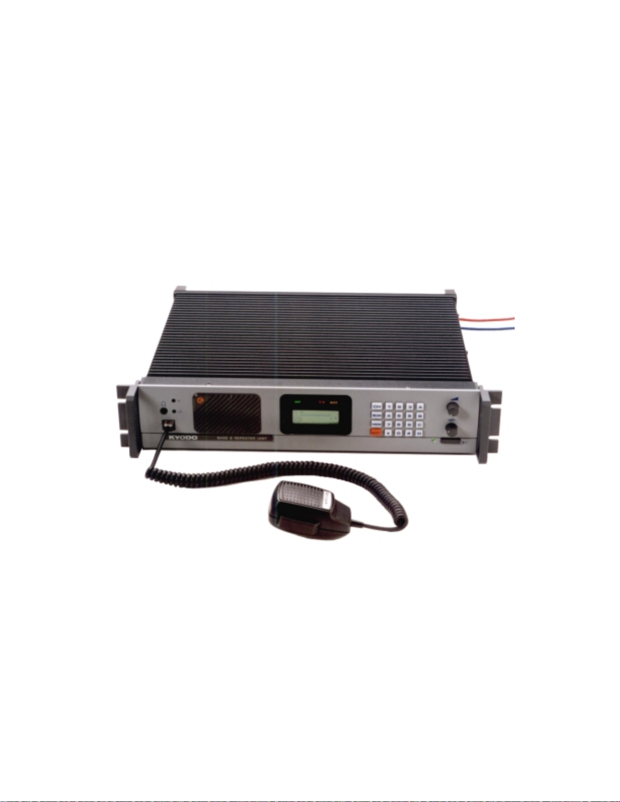
KYODO KG510 BASE/REPEATER
Page 2
KYODO KG510 OPERATORS MANUAL
CONTENTS
SECTION DESCRIPTION PAGE
1 INTRODUCTION
2 PRODUCT DE SCRIPTION
2.1 Features
2.2 Product Descriptio n
2.3 Standard Inclusio ns
3
4
CONTRO LS , INDICATORS, & CONNECT ORS
3.1 Front Panel Controls 5-7
3.2 Rear Panel Connectors 7
OPERATION
4.1 Installation and Program ming
4.2 Basic Operat ion 8
4.2.1 Switch On
4
4
4
4
5
5
8
8
4.2.2 Adjust the Volume Setting
4.2.3 Adjust the Squelch Setting
4.2.4 Select the Channel
4.2.5 Receiving
4.2.6 Transmitting
4.3 Front Panel Operat ion
4.3.1 Keypad Operation
4.3.2 Keypad Operat ion using the SHIFT Key
4.3.3 Changing Channels
4.4 Signalling
4.4.1 5-Tone Signalli ng
4.4.1. 1 Available Tones 11
4.4.1. 2 Entering 5-To ne Encoding Seq uences
4.4.1. 3 Recalling the Last Encode Sequence 12
4.4 2 DTMF Signalling
4.4.2. 1 Available Tones 12
4.4.2. 2 DTMF Tone Entry
8
8
8
8
8
9
9
10
11
11
11
11
12
12
128194 Page #2 of 26 Pages 11 December, 2000
Page 3

KYODO KG510 OPERATORS MANUAL
CONTENTS
SECTION DESCRIPTION PAGE
4.4.2. 3 Redialling with DTMF
4.4.2. 4 Restoring the Last DTMF Numbers to the LCD Display
4.4 3 Single Tone Encoding 13
4.4 .4 Kill Sig na lling
4.4 .4. 1 Kill Sig n a lli ng O p eratio n 14
4.5 Channel Scanni ng
4.5.1 All Channel Scan Operat ion
4.5 2 Program Channel Scan Operatio n 16
4.5.3 Exiting Scan Modes
4.5.4 Priority Scanning 16
4.5.5 Removing Channels from Scan List
4.5.6 Restoring Channels to the Scan List 17
4.6 Locking the Key Pad
4.7 Changing Tone Signalling Systems
4.8 Displaying Channel Informatio n
4.9 Displaying Received Tone Freq uencies
4.10 Bar Graph Displays
4.11 LCD Display Back Lig ht
4.12 Transmit Power Change
4.13 Calling Party ID Display
4.14 Displaying any Radio's I D Number
4.15 Emergency Caller Display
4.16 Automatic Tra nsmit in Repeater Mode
4.17 TX Test Mode
4.18 Key Pad Test Mode
4.19 Frequency Band Test Mode
13
13
14
15
15
16
17
17
18
18
19
20
20
20
21
21
22
22
23
23
24
4.20 Starting Message 24
4.21 Serial Number Display 25
4.22 EEPROM Data Check Mo de 25
4.23 Hardware Error Detection 26
4.24 RS232C Communications Error Messages 26
128194 Page #3 of 26 Pages 11 December, 2000
Page 4

KYODO KG510 OPERATORS MANUAL
1.0 INTRODUCTION
Thank you for purchasing a KY O DO KG510 Base or Repeater .
We t rust that it will operat e reliably and give you years of service. If not, or if you wish to suggest ways of
improving the KG510's operation, or f eatures, w e would welcome your comments.
2.0 FEAT URES & PROD UCT DESCRIP TIO N
2.1 Features
Simplex or two frequency Duplex operation
!
EEPROM pr og rammable with a PC comp uter
!
Single Channel and 99 Channel Versions
!
available
Full Dot Mat rix Liq u id Crys tal Displa y
!
All FM Frequency Bands from 30 to 520 M Hz
!
Front Facing Speaker
!
Transmit Time Limiter to prevent channel
!
jamming
TX and RX Encrypt io n
!
Two Channel Scanning Modes
!
5 Tone Encoder & Decoder plus DTMF Encoder
!
Up to 99 channels with Channel Labels
!
Two-Stage Front End allows mixed Simple x and
!
Duplex operation
Channel selectable Wide or Narrow channel
!
spacing
CTCSS/DC S on a per channel basis
!
5 X 4 Keypad for Channel Change etc
!
2RU Equipment Cabinet
!
Step-Up VCO Voltage for Superior Selectivit y
!
Low Stand-by Current is ideal for Solar
!
Installations
Watch Dog Timer
!
& Decoder
22, 26, or 35 MHz switchi ng bandwidth (model
!
dependant)
2.2 Product Description
Kyodo KG510
The
transceivers represent a quant um adva nce on the previous rugged & time pr oven KG110
transceiver. They co mprise of separ at e modules all housed within one 2RU equipment cabinet. The r ec ei ver,
the transmitter , and the PA Unit are each enclosed w ithin their own diecast housing, that are then d irectly
mounted on the large upper heat-sink. A µProcessor controlled interface module controls the channel
selection, LCD Display, t imers, interfac es, and signalling features.
Models are available for all FM commercial and military frequency bands from 30 MHz to 520 MHz, with
channel selectable 12. 5, 20, 25, or 30KHz channel spacing arrangements.
The RF Power Output is 1 - 50 Watts on a continuous duty basis. T he CTCSS module supports all EIA
tones. All tones and different encode and decode tones can be set on a per channel basis during radio
programming.
The KG510
includes 5 tone Selective Calling encoder/decoder with non-predictive decoder, as well as a
DTMF encoder, and voice encryption. It supports normal all channel scanning and programmed channel
scanning for base use.
KG510
The
is fitted w ith a large full dot matrix LCD that is used to display the Channel Number s & Names,
frequency & tone program med informatio n, and signalling information. All user interface keys and knobs are
conveniently located on the front of the radio. All user entered functions are easily activated in a logical
manner via the keypad.
KG510
The
is supplied with an "N" Type connector for the transmitter, and a TNC Connector for the
Receiver to allow easy connectio n to the diple xer or f eeder c ables.
The rear panel includes a 9 way D sub connector for f itment of an external s hared tone panel. Also included
is a 25 way D sub connector t hat enables exter nal interfac e t o ot her radios or control equipment.
128194 Page #4 of 26 Pages 11 December, 2000
Page 5
KYODO KG510 OPERATORS MANUAL
2.3 Standard Inclusions
The KG510 transcei ver is supplied comp let e w it h the following items:
KG510 tr ansceiver
DC Cab le
Operat or s Manual
KD561 Hand Microphone
3.0 CONTRO LS , INDICATORS, & CONNECT ORS
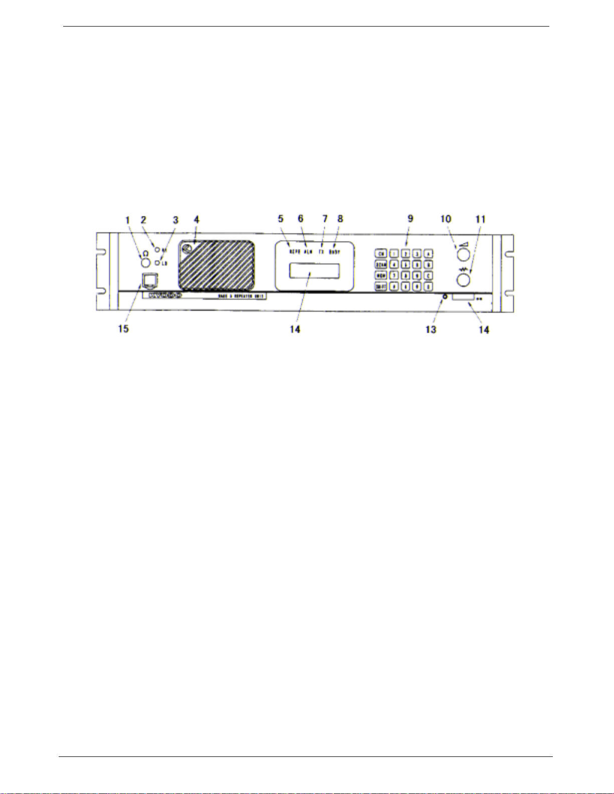
3.1 Front Panel Controls
Headphone Socket
1.
1.
1.1.
This socket is provided to allow users to listen to the KG510 using headphones. Plugging a
headpho ne into this s o c k e t will d is c on nect the built-In spea k er. It does NOT include a micr o pho n e
inp ut , or TX PTT facility.
High TX Po wer
2.
2.
2.2.
This is a service point and is not used by the radio operators
Low TX Power
3.
3.
3.3.
This is a service point and is not used by the radio operators
Loud Speaker*
4.
4.
4.4.
The receiver audio signals are heard from this speaker (pr ovided that the volume sett ing is loud
enough and provided that the speaker has not been muted by one of the tone signalli ng formats .
Repeater Mode I ndicator LED
5.
5.
5.5.
The Repeater Mode Indicator LED will illuminate "REP" in Yellow colour when the selected
channel has been programmed for Repeater operation. This LED is NOT illuminated on any
channel that is programmed to oper at e in Base mode.
Alarm Mode Indicator LED
6.
6.
6.6.
The Alarm Mode Indicator LED will illuminate (Flashing) "ALM" in Orange colour whenever the
transceiver detects a fault in the receiver module, the transmitter module, or the PA module on
the selected channel.
128194 Page #5 of 26 Pages 11 December, 2000
Page 6

KYODO KG510 OPERATORS MANUAL
Transmit Mode I ndicator LED
7.
7.
7.7.
The Transmit Mode Indicator LED will illuminate "TX" in Red colour whenever the KG510 is
transmitting.
Busy Mode Indicator LED
8.
8.
8.8.
The Busy Mode Indicator LED will i llumi nate "R X" i n Gree n colo ur whe nev er t he KG5 10 r eceives
a carrier signal on the selected channel that is great er t hen the Squelch setting.
Keypad*
9.
9.
9.9.
The 5x4 key Keypad is used to enter channel select ion, tone informatio n, and other data into the
KG510. Specific key sequences are descr ibed fully in section 4 of t his doc ument. I t includes t he
following keys: CH, SCA N, MON, SHIFT, 1, 2, 3, 4, 5, 6, 7, 8, 9, 0, , #, A, B, C, and D.
Vol ume Control*
10.
10.
10.10.
The Volume Control is used to set the audio o utp ut level from the loudspeaker . Rotate t his knob
clockwise to increase the audio le vel, or counter-clockwise t o r educe the audio level.
Squel ch Control *
11.
11.
11.11.
The Sq uelch Control is used to set t he squelch t hreshold. Select a channel t hat is not being used
and slowly rotate this knob clockwise until the annoying background noise ceases. It may be
desirable to rotate this knob clockwise slightly past the squelch threshold to compensate for
varying background noise le vels.
Power ON/OFF Switch
12.
12.
12.12.
The Power ON/OFF Switch is used to switch the KG510 "ON" or "OFF". Press this knob to switch
the KG510 "ON". Press this knob agai n t o switch the KG510 "OFF". This knob is slightly more
depressed w hen in the "ON" position.
Power On Indicator LED
13.
13.
13.13.
The Power ON I ndica tor LED w ill i llu mina te in G ree n colo ur w hene ver t he Pow er O N/O FF sw itc h
is switched to the "ON" positio n.
Liquid Crystal Display (LCD)*
14.
14.
14.14.
The LCD comprises of four (4) lines each of which is capable of displaying twenty-one (21)
characters.
The first line, in normal operati ng condition, displays the st rength of the signal bei ng recei ved on
the selected channel as a bar graph.
The second line displays the strengt h of t he transmitt i ng power as a bar graph.
The t hird line displays the selected channel number (up to four characters) in the first five left
hand character spaces, and displays the channel name (up to eight charact ers) in the next eight
character spaces.
The followi ng character s may be used in the channel name:
0-9, A-Z, a- z, / + - # ! $ % ( ) = [ ] < > ? and space
This area of t he LCD is left blank when channel names are not used.
128194 Page #6 of 26 Pages 11 December, 2000
Page 7
KYODO KG510 OPERATORS MANUAL
The si x c haracter spaces on the rig ht hand side of this line are used to display status symbols as
follows:
a. The monitor status. --- symbol is
b. The key lock status. --- symbol is
c. The to ne encode stat us. --- symbol is
d. The scan mode st at us. --- symbol is
e. The high power transmit status.--- symbol is
f. The [SHIFT] key status. ---This symbol is displayed whene ver the [SHIFT] key is
The fourth li ne displays (in t he lef t hand four character spaces) the type of tone signa lling system
selected by the user. e.g. "5TON" means 5 To ne sig na lling while DTMF means Dual Tone M ulti
Frequency signalling.
The right hand sixteen character spaces are used to display data that the user enters (e.g. 5
Tone calling sequences). These character spaces are also used by the KG510 to display
messages and information dir ect ed t o the us er .
Microphone Input Socket
15.
15.
15.15.
Connect the supplied Kyodo KD561 micr ophone into this socket.
* Not used on t he Single Channel Model
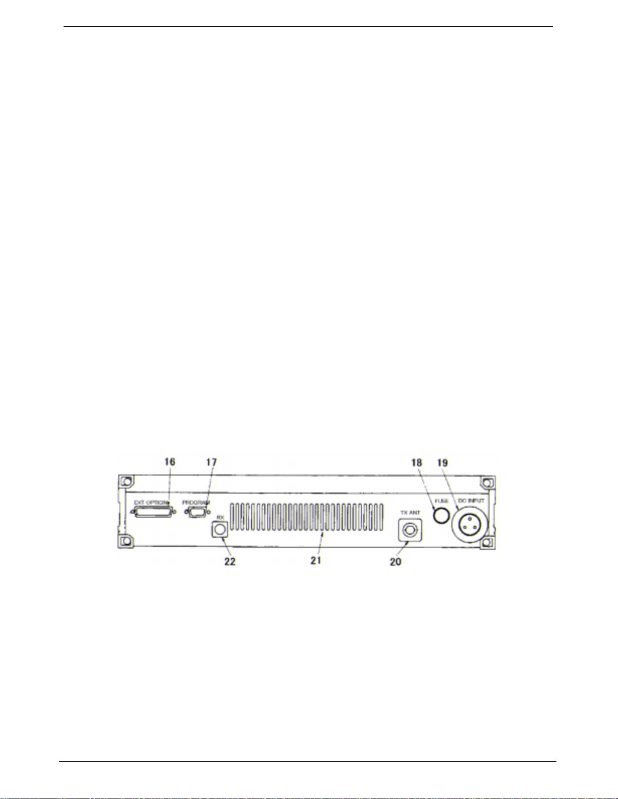
3.2 Rear Panel Connectors
ϕ
held depressed.
25 way External Options Connector
16.
16.
16.16.
9 way Progr amming Connector
17.
17.
17.17.
DC Input F use Holder
18.
18.
18.18.
3 way DC Input Socket
19.
19.
19.19.
TX/Antenna Co nnector ( N type)
20.
20.
20.20.
Ve ntila tion Slots
21.
21.
21.21.
RX Connector (B NC type)
22.
22.
22.22.
128194 Page #7 of 26 Pages 11 December, 2000
Page 8

KYODO KG510 OPERATORS MANUAL
4.0 OPERATION
4.1 Installation and Progr am ming
As the KG510 can be installed to operate as either a Base Station or as a Repeater, some of the
instructions in t his document may apply to one application only, some may apply in bot h cases, while
others may only apply if the particular f unctio n has been enabled during pr ogr amming of the KG510.
The KG510 must be progr ammed before it will oper ate corre ctly. This is best done by the eq uipme nt
supplier or a competent radio trades man. They will r eq uire t he Kyodo 51 BS pr ogr ammi ng sof tw ar e t o
do this correctly.
It is important that t he KG 510 be correct ly installed at its working location. It is recomme nded that this
be done by a competent radio tradesma n.
As a mini mum, it is necessary to:
Connect the DC Input power lead to a suitable 13.8 Volt Reg ul ated DC Power supply t hat
•
has sufficient capacity. ( Ensure that the DC Polarity is correct) .
Connect the two antenna connectors to suitable antennas. (Ensure that the VSWR of the
•
antennas is correct) .
Insert the Kyodo KD561 Microp hone into the microp hone connector on the front panel.
•
4.2 Basic Operation
4.2.1 Switch On
Switch the KG510 "ON" by pressi ng the knob (12) and then check that the LED indicator ( 13)
is illuminated.
4.2.2 Adjust the Volume Setting
Rotate the Volume Knob (10) clockwise (from the fully counterclockwise position) until the
audio level from the speaker is suitable.
4.2.3 Adjust the Squelch Setting
Rotate t he Squelch Knob clockwise (from the fully counter clockwise positio n) s lowly until t he
background noise ca n no l onger be heard. It is wise to slightly rotate the knob further in t he
clockwise direction (so that variations in the background noise level do not "break" the
squelch setting and cause annoying squelch noises to be heard fr om the speaker).
4.2.4 Select the Channel
Select the required channel by pressing the [SHIFT] key followed by the channel number
keys within two seconds. E.g. [SHIFT] + [0] + [1] to select channel #1. The LCD Display
should now display CH01 and (if programmed with a channel label) the channel name:
"CH01 Kyodo-co".
4.2.5 Receiving
You sho uld now be able to hear any radio traf fic t hat occurs on cha nnel #1 on the KG510. It
may be necessary to further slightly adjust the Volume setting to suit your listening
requirements.
4.2.6 Transmitting
Dependi ng on the lega l requirements i n your country, and the operating r equirements w ithin
your orga nisatio n, it may be necessary to announce your Call Sign, and will probably be
necessary to announce the Call Sign of the party you are calling at the start of your
transmission.
Whe n transmitting, it is necessary to hold the microphone about 75mm (3") from your mouth
and speak clearly into the grill of the m ic rophone.
It is also necessary to press and hold the Press To Talk (PTT) bar on the side of the
microphone depress ed w hile speaki ng into the microp hone.
128194 Page #8 of 26 Pages 11 December, 2000
Page 9

KYODO KG510 OPERATORS MANUAL
4.3 Front Panel Operation
This section desc ribes most sig nalling a nd other advanced feat ures that are availab le on the KG 510
Transceiver. The availability of some features is dependent on the programming of the transceiver.
You may fi nd it wort hw hile to disc uss these features i n detai l with your radio supplier to obtain a full
understanding of their benefits.
4.3.1 Keypad Operation
The Keypad is the interface between the user and the KG510 and is used to enable or
disable various f unctio ns, and to enter the requir ed data for signalling purposes.
(5-Tone) or (DTM F) shown after the described feat ur e indicates t hat the descr ibed feature
applies to the partic ular signalling f or mat.
The followi ng keys are used for t hese purposes:
[0] - [9] Entering new channel numbers
Entering the "KILL" passwor d
Entering signal ling encod i ng numbers (5-Tone) (DTMF)
Entering DTMF numbers ( DTMF)
[A] Advancing the KG510 to t he next higher channel
Entering the sig nalling "A" tone (5-Tone) (DTMF)
Encodes the "A" Tone (DTMF)
[B] Advancing the KG510 to t he next lower channel
Entering the sig nalling "B" tone (5-Tone) (DTMF)
Encodes the "B" Tone (DTMF)
[C] Entering the signalling "C" tone (5-To ne) (DTMF)
Encodes the "C" Tone (DTMF)
[D] Entering the signalling "D" tone (5-To ne) (DTMF)
Encodes the "D" Tone (DTMF)
[ ] Displays t he previo usly entered encode numbers (5- Tone)
(DTMF)
Encodes the " " -Tone (DTMF)
[#] Encodes the signalling numbers that are displayed in the LCD display (5-Tone)
(DTMF)
Encodes the "#"-Tone (DTMF)
[CH] Used with two channel numbers [0] - [9] to change the active channel on the
KG510. E.g. [CH]+[9]+ [0] will cha nge the active channel to Cha nnel 90 (provided
Ch 90 has been programmed into the KG510.
[SCN] Used to place t he KG510 i nt o the "All-Scan" mode where the KG510 will sc an all
programmed channels. Pressing the [SCN] key again will cause t he KG510 to exit
from the "All-Scan" mode.
[MO N] Switches the KG510 betw een "Monitor ON" mode and "Monitor O FF" mode and is
used to "Un-mute" the radio when using selective calling (depending on the
programmi ng of the KG510 tr ansceiver).
128194 Page #9 of 26 Pages 11 December, 2000
Page 10

KYODO KG510 OPERATORS MANUAL
4.3.2 Keypad Operat ion using the [S HIFT] Key
Some of the KG510's features and how it operates can be cha nged by using the [SHIFT]
key. To make these changes, it is necessary to fir stly press the [SHIFT] key followed by t he
other keys within a two second timeframe.
The following key seque nces are used for these pur pos es:
[SHIFT]+[0] Toggles the t one system between 5-To ne signalli ng and DTMF signalling.
[SHIFT]+[ 1] Switches the LCD back-light ON or OFF.
[SHIFT]+[2] Toggles the transmitt ing power bet ween High power and Low power.
[SHIFT]+[3] Invalid Key.
[SHIFT]+[4] Toggles between "Single Tone Encoding" mode and "5-Tone" or "DTMF"
signalling mode.
[SHIFT]+[5] Invalid Key
[SHIFT]+[6] Enters t he KILL mode to allow e ntry of the KILL passwor d.
[SHIFT]+[7] Displays the programmed i nformatio n for t he selected (active) channel in
the LCD display.
[SHIFT]+[8] Locks or Unlocks t he KG510's Keypad.
[SHIFT]+[9] Toggles the KG510 betw een "Normal Cha nnel Scanning" mode and "Pr iority
Channel Scanning" mode.
[SHIFT]+[A] Restores a channel to the Channel Scanning List. (The user must firstly
select the channel to be rest or ed as the active channel).
[SHIFT]+[B] Invalid Key
[SHIFT]+[C] Indicates to the KG510 that you have entered the last number of a DTMF
encodi ng sequence.
[SHIFT]+[D] Invalid Key
[SHIFT]+[ ] Deletes the active c hannel f r om the Channel Sca nning List.
[SHIFT ]+[ #] Will at tach th e "R- Number" d ata t o t he active e ncode number a nd tr ansmit
the whole sequence.
[SHIFT ]+[C H] W ill s tar t or st op the dis play o f the TX a nd RX bar gr ap hs in the LC D d is p lay.
[SHIFT ]+[ SCN] Will plac e t he KG510 in the Program Scan mode or exit from the Pr ogram
Scan mode.
[S HIFT]+[ MO N] In v alid Ke y.
128194 Page #10 of 26 Pages 11 December, 2000
Page 11

KYODO KG510 OPERATORS MANUAL
4.3.3 Changing Channels
To change to another channel, simply press the [CH] key followed by the number of the
required channel wit hi n tw o seconds.
e.g. To select Channel # 8, pr ess [ CH] [0] [8]
To select Channel # 99, press [CH] [9] [9]
Note that it is always necessary to enter two digits for the Channel Number.
The c ha nnel # location disp layed in the LCD will become blank as soon as the [CH] key is
pre ssed , and the c ur sor will blink at the loc at ion of the c ha nnel nu mber , and dis p lay t he new
numbers as they are entered.
It is also possible to change channels by using the [A] and [B] keys instead of entering the
channel numbers.
Pres si ng the [ A] key will adva nce t he cha n nel to t he ne xt hig her p rog rammed c ha nnel, w hile
pre s s ing [B] will advance t he cha nnel to t he next lower progr ammed c hannel.
Note t hat t his actio n will ig nore chan ne ls that have
Accordingly, the LC D disp lay may appear to advance more than one channel if the missed
channel is not programmed into the KG510.
not
been programmed into the KG510.
4.4 Signalling
The KG510 includes some very sop histic ated signalling capab ilities. We suggest that you have your
radio supplier conduct some tr ai ning on the use of these capabilities prior t o using t hem.
While it is possible to use these signalling capabilities in both repeater mode, and in base station
mode, many will o n ly b e use ful i n pr a c tice whe n the KG510 is used in base station configuratio n.
The KG510 supports the 5-Tone sequential, and/or the DTMF, and the Single Tone sig nall ing for mats.
The required sig nalling format( s ) must be enabled whe n the KG510 is programmed.
4.4.1 5-Tone Signalling
4.4.1.1 Available Tones
5-Tone signalling is commonly referred to as Selective Calling (or Selcall) and usually
comprises of a series of 5 tones sequentially transmitted or received in accordance with
certain international standards. It is possible to use longer sequences to enhance the
signalling capabilit ies and to provide further functions.
Accordingly, the KG510 will e ncode up to sixteen (16) tones and decode up to eight (8)
tones.
These tones can be any of the following:
[0] - [9], and [A] - [D]
The most recently entered tone can be recalled and deleted by pressing the [ ] key
repeatedly.
4.4.1. 2 Enteri ng a 5-To ne Encode Sequence
When switched "ON", the KG510 carries out its self-test routine, and then waits ready to
accept 5-Tone e ncode numbers. Accordingly, it is only necessary to enter the required 5Tone digits directly usi ng t he keypa d, and then pressing the [#] key to transmit the 5-Tone
sequence. (Up to sixteen digits can be entered) .
If it is necessary to enter t he "R" number seq uence to activate the repeater, the [SHIFT] ke y
must be pressed bef or e pressing the [#] key .
If a 5-Tone number is NOT displayed in the LCD, and the [#] k ey is pr ess ed, t hen the KG510
will reca ll the mos t re c e nt 5 -Tone n u mbe r and t ransmit it .
128194 Page #11 of 26 Pages 11 December, 2000
Page 12

KYODO KG510 OPERATORS MANUAL
4.4.1. 3 Recalling t he last encode seque nce
Pressing the [ ] will recall the most recent 5-Tone encode sequence and display the
seque nce i n t he LCD disp lay. Further pres ses of t he [ ] key will dele te the las t digit of the
seque nce unt il all d igit s ar e dele ted . I n prac tic e users will us ually de let e the last o ne or tw o
digits before entering the new digits.
4.4.2 DTMF Signalling
4.4.2.1 Available Tones
The followi ng DTMF tones can be used:
[0] - [9], [A] - [D], [ ], and [#]
NOTE:
Tone [B] is NOT availab le if the "Attach Decode No" field in the DTMF Encode Menu
has been set to "ON".
Up to sixteen (16) DTMF digits can be encoded in one calling sequence.
4.4.2. 2 DTMF Tone Entry
There are two methods of entering DTMF tones. The specific tone encoding format is
selected during the programming of the KG510 transceiver in the <Main Menu><Encode
Set>< DTMF Encode><At t ach Decode No.> field.
4.4.2. 2.1 Attac h Decode No. "OFF" for mat
Pressing the PTT lever first automatically selects the DTMF encoding format and allows
direct entry of DTMF tones.
Hold t he PTT lever on t he microp ho ne depressed while pressing the required DTM F tones .
The tones w ill b e tra nsmitted a s the keys a re being pres s ed .
4.4.2. 2.2 Attac h Decode No. "O N" format
Attach Decode No. "O N" automatical ly encodes the users DTMF decode number after the
encode number. This ca n be used for ANI purposes.
Enter the req uired DTMF tones (up t o sixt een tones except "B" tone) and then transmit the
total tone sequenc e (incl udi ng t he users decode number) by pressing the [#] key . All tones
will be tr ansmitted in one conti n uo us s eque n c e a fte r pr e s s ing t he [ # ] key .
Pres s ing the [ ] ke y will dele te t he las t ente r e d nu mbe r.
Always conf irm t hat the LCD is cle ar before proc eeding as it may take up to 5 seconds for
the tones to be sent.
e.g. Assume that your decode number is 12345, and that you wish to encode number
12346. You will i np ut 12346, and then press the [#] k ey. The KG510 will e ncode
12346B12345. The call ed r adio w ill d is pla y 12 3 45 in the ir LCD i ndicati ng the
calling party's number is 12345.
NOTE: The "B" tone is used as the delimiter in this encoding format and t herefor e CA NNOT
be used as a DTMF tone.
Pres s ing the [S HIFT] ke y a nd t hen t he [ #] w ill e ncod e ONLY the encode number (and not t he
decode number).
128194 Page #12 of 26 Pages 11 December, 2000
Page 13

KYODO KG510 OPERATORS MANUAL
4.4.2. 3 Redia lling with DTMF
If during the programming of the KG510, the <Attach Decode No> field has been set to
"OFF", t he redialling functio n operates as follows:
Press [SHIFT], t hen press [ #] and the KG510 will red ial the last encod e d DT MF n umb er.
If during the programming of the KG510, the <Attach Decode No> field has been set to
"ON", the redialling functio n operates as follows:
Press [#] and the KG510 will redial the last encoded DTMF number
programmed decode number.
Pres s [SHIFT] , and then press [#] and t he KG510 will r edia l t he last e ncoded DTMF number
without
the KG510's program med decode number.
4.4.2. 4 Rest or ing the last DTMF number to t he LCD Display
It is possible to restore the last encoded DTMF number to the LCD display, provided the
<Attach Decode No> field has been set to "ON" during the programming of the KG510
transceiver.
Confirm that the LCD is NOT displaying any DTMF numbers, then press [✶] and the last
encod e d DTMF numbe r will be dis p la y e d in the LCD d is p la y .
It is possible to edit this number at this time by pressi ng t he [✶] key (which will er ase the last
number) or by pr essing the required keys to add additional numbers.
4.4.2.5 Encoding DTMF numbers with the 5-To ne system enabled
It is possible to ent er DTM F numbers even with the 5-Tone system e nab led. This function
must be enabled during the program mi ng of the KG510 by setting the <DTMF Encode> field
in the <5Tone Encode Menu> to "ENABLE".
To enter a DTMF number (with 5-Tone signalling enabled), the user must press the PTT
lever while entering the first DTMF number. Second and subsequent numbers do NOT
require the PTT lever to be pr essed provided all numbers are entered within a few seconds
(befor e the display reverts t o 5- Tone mode and displays "5TON" in the LCD display) .
with
the KG510's
4.4.3 Single Tone Encoding
The KG510 has the ability to encode one of six single tone frequencies for 1, 2, 3, or 4
seconds. This functio n is enabled d uring program mi ng of the KG510 by selecti ng the <Single
Tone ON> field in the <Encode Menu> and sett ing the encode period.
Press the [ SHIFT] and the [4] keys to put the KG510 i nto Single Tone Encoding mode. "S1"
and t he tone fr equency ("xxxxHz") will be disp layed i n the t one ar ea of t he LCD dis play f or
about 4 seconds until the KG510 revert s back t o the normal sig nall i ng mode.
While the KG510 is in Single Tone Encoding mode, it is possible t o advance to the next tone
frequency by pressing the [A] key, or to return to the previous tone by pressing the [B] key.
Pres sing the [ #] key will encode the displayed tone (for the programmed time period) and
automatically exits the Single Tone Encoding mode and returns the KG510 to the normal
signalling mode.
128194 Page #13 of 26 Pages 11 December, 2000
Page 14

KYODO KG510 OPERATORS MANUAL
4.4.4 KILL Signalling
The KG510 has the ability t o transmit a specially coded signalli ng sequence that w ill disab le
("KILL") another radio. This feature is particularly useful when transceivers become
misplaced, are stolen, if they are used in an incorrect manner, or if they are used for the
wrong purposes.
To prevent accidental or mischievous "KILLI NG" of radios, several security features are in
place.
Firstly, the KG510 must have this functio n enabled d uri ng program ming.
Secondly, the user must know the req uired passw ord and e nter it cor rectly into t he KG510,
and,
Thirdly, the user must know the required "KILL" number ( of the r adio to be "KILLED", and
enter it correc t ly into the KG510.
The "KILL" password has four numerica l digits. [0] to [9].
With 5-Tone signalling systems, the "KILL" number for a particular radio comprises of the
radio's decode number + D + the radio's KILL number.
With DTMF signalling systems, the "KILL" number for a particular radio comprises of the
radio's decode number + A + the radio's KILL number. I n the case of DTMF signalling, both
the decode number and the KILL number must have more than four digits.
4.4.4. 1 Kill Signalling Oper at ion
Press [SHIFT] and the press [ 6] to place the KG510 int o the KILL mode.
The LCD d is play will i ndicate that t he KG510 is in the KI LL mode
RX
TX
CH01 Kyodo-co
Kill Pass --
Enter the required passwor d by enteri ng the correct f our digit number.
If the password has been correctly entered, t he LCD display will show this message:
RX
TX
CH01 Kyodo-co
Kill Pass OK
Then e nt er the "KILL" data f rom the keyboard that comprises of the decode number + D +
the KILL number of the radio to be "KILLED". (In the case of DTMF signalling, it will be
necessary to substitute the "A" tone instead of the "D" tone).
Then press [#] to transmit the data.
128194 Page #14 of 26 Pages 11 December, 2000
Page 15

KYODO KG510 OPERATORS MANUAL
y
If the incorrect password has been entered, the LCD display will show the following
message:
If you enter the "KILL" data prior to ent ering the KILL passw ord, and then press the [ #] key,
the LCD display w il l show the followi ng message:
If the incorrect pass word has been entered more than the allowed number of tries, then t he
KG510 becomes disabled a nd the following message is displayed in the LCD display:
RX
TX
CH01 Kyodo-co
Kill Pass NG
RX
TX
CH01 Kyodo-co
Input Password
Not Read
In suc h cases, it is necessary to r eturn t he KG510 to your radio supplier to have the KG510
repaired.
4.5 Scanning
The KG510 is supplied with two scanning modes. These are All Channel Scan mode in which the
KG510 will s can all c hannels that ar e progr ammed into the KG510 , and t he Progr am Channel Scan
mode in which the KG510 will scan only the channels that have been designated during the
programmi ng of the KG510 tr ansceiver.
Furthermore, one HIGH priority, and o ne LOW prior ity scan channel can be set for each scan mode
during the programming of t he radio.
4.5.1 All Channel Scan Operatio n
Pressing the [SCAN] key places t he KG510 into All C hannel Scan mode and t he Scan mode
symbol " " is disp la yed i n t he LCD disp lay . Als o t he LCD w ill dis pla y "A ll Sca n M ode- i n" f or
two s econds as shown below:
RX ======
TX
CH01 Kyodo-co
All Scan Mode-in
•
128194 Page #15 of 26 Pages 11 December, 2000
Page 16

KYODO KG510 OPERATORS MANUAL
4.5.2 Program Channel Sca n Operat ion
Pressing the [SHIFT] and then the [SCAN] key places the KG510 into Program Channel
Scan mode and the Scan mode symbol " " is displayed i n the LCD display. Also the LC D will
display "PRG Scan Mode-in" for t wo seconds as shown below:
RX ======
TX
CH01 Kyodo-co
Prg Scan Mode-in
•
4.5.3 Exiting All Channel Scan and Program Channel Sca n modes
Pressing the [SCAN] key will take the KG510 o ut of either scanning mode and return the
KG510 to normal mode. The scan symbol " " w ill be r emo ved f rom t he LC D displ ay a nd t he
LCD will d isp la y "S c an Mode- out" for two s econds as shown below:
4.5.4 Priority Scanning
The KG510 allows users to firstly enter the required scanning mode, and then they can
enable Priority Sca nni ng for t he particular sca nning mode c hosen.
Pressing the [SHIFT] key and then the [9] key places the KG 510 into Priorit y Sca nning mode
as shown below:
Pressing the [SHIFT] and t he [9] key s again w ill tak e the KG5 10 out o f Prior ity Sc an mode
and retur n to the Normal Scan mode as shown below:
RX ======
TX
CH01 Kyodo-co
Scan Mode-out
RX ======
TX
CH01 Kyodo-co
Priority Scan
•
RX =====
TX
CH01 Kyodo-co
Normal Scan
128194 Page #16 of 26 Pages 11 December, 2000
•
Page 17

KYODO KG510 OPERATORS MANUAL
4.5.5 Removing an Active Channel fr om the Scan List
It is possible to temporar ily delet e an active channel from the scan list by pressing [SHIFT]
and the [ ] key and holding the [SHIFT] and the [ ] keys depressed for more than one
second. More tha n one channel can be delet ed from the Scan list, provided t hat at least one
channel remai ns in the Scan List.
A "beep" sound from the radio confirms corr ect deletion of the channel fr om the scan list.
This function CANNOT be used in the Priority Scan mode.
The KG510 automatical ly restores all channels to their respect ive sca nning list as soon as
the KG510 exits fr om the scan mode.
4.5.6 Restoring Channels t o t he Scan List
Channels can be restored to the scanning list without exiting from the scan mode by
pressing the [ SHIFT] key and press ing and holding the [A] key depressed for more than one
second.
This ac tion will r e s tor e a ll c ha nnels t o t he scan list.
This action CANNOT be used in the Priority Sca n mode.
4.6 Locking t he Keypad
Pres si ng the [S HIFT] ke y and th e n the [8] ke y w ill lock a ll keys (exce pt t he [S HIFT] a nd [ MO N] k eys )
on the KG510's keypad to pr event accidental or inadvert ent entry of data.
After pres sing the [ SHIFT] and [ 8] keys the keypad becomes locked and the Key-Lock sy mbol is
displayed in the LC D display. The display also shows "Key-Lock" for two seconds as shown below:
RX ======
TX
CH01 Kyodo-co
Key Lock
•
Pressing [SHIFT] and [8] again will Unlock the keypad, remove the Key-Lock symbol from the LCD
display, and display "Key-Unlock" in the LCD display for tw o s econds as shown below:
RX ======
TX
CH01 Kyodo-co
Key Unlock
128194 Page #17 of 26 Pages 11 December, 2000
Page 18

KYODO KG510 OPERATORS MANUAL
4.7 Changing Tone Sign alling Systems
It is possible to switch the KG510's tone signalli ng system among 5-Tone sequential signalli ng,
DTMF signalling and Non(No-Tone system) (providing the <Miscellaneous Menu> <Tone System
Change> field was set to "ENABLE" during the programmi ng of t he KG510).
Press [SHIFT] and keep depressed t he [0] key for more than one second to change am ong 5-To ne
system, DTMF system and Non and indicate new signalling system in the LCD display as follows:
RX ======
TX
CH01 Kyodo-co
System is DTMF
Pressing [SHIFT] and pressing the [0] key for more than one second again will change next the
signalling system and indicate new signa ll i ng system in the LCD display as shown below:
RX =======
TX
CH01 Kyodo-co
System is Non
4.8 Displaying the Channel Information
The KG510 can display information pertaining to the selected channel (provided that the
<Miscellaneous Me nu> <Information Display> field was s et to "ENABLE" during the programmi ng of
the radio.
This information is:
The RX frequency of the selected channel.
!
The TX frequency of the selected channel.
!
The channel spacing f or t he selected channel (Wide or Narrow) .
!
The operating mode for the selected channel (Base, Repeater , simplex, duple x)
!
The RX CTCSS/DCS tone for the selected channel (provided CTCSS/DCS has been
!
programmed for use on the selected channel) .
The TX CTCSS/DCS tone for the selected channel (provided CTCSS/DCS has been
!
programmed for use on the selected channel) .
The tone encoding for mat (pr ovidi ng 5-To ne signalling was selected duri ng progr amming of the
!
KG510).
The tone set (providing 5-Tone signalling was selected dur ing programming of the KG510).
!
The ANI mode.
!
The t one decoding set ( provided 5-To ne or DTMF signalling was selected during progra mming of
!
the KG510).
The decode number (provided 5- Tone or DTMF signalling was selected dur ing progr amming of
!
the KG510).
128194 Page #18 of 26 Pages 11 December, 2000
Page 19

KYODO KG510 OPERATORS MANUAL
To view this informatio n in the LCD display, f ir st ly select the r equired channel. Then press t he [ SHIFT]
key a nd t hen t he [ 7 ] key . You w ill need to keep the [7] key pr essed until the KG510 has cycled thro ugh
the information steps.
This function is NOT availab le if the <Miscellaneous M enu> <Informatio n Display> field has bee n set
to "DISABLE" duri ng the pr og r a m mi ng of t he KG 510.
4.9 Display of Received Tone Fr equenci es.
It is possible to set the KG510 to display the received tone frequenc ies in the LCD display in the area
normally used to display the str engt h of the received sig nals.
Press [SHIFT] and then press [D] to enable this functio n.
Once enabled, the LCD will show "RCV" in the area of the LCD display that normally shows the
strength of the received signal, as w ell as "Tone Display on" for two s econds as shown below:
RCV
TX
CH01 Kyodo-co
Tone Display On
Then, whenever a tone frequency is decoded, the frequency number will be displayed in the LCD
display to the right of "RCV" as shown below:
RCV 12345
TX
CH01 Kyodo-co
5TON
Pressing the [SHIFT] key and then the [D] key once again will disabl e t his f unct ion a nd r et ur n the LCD
display to normal as shown below:
RX
TX
CH01 Kyodo-co
Tone Display Off
128194 Page #19 of 26 Pages 11 December, 2000
Page 20

KYODO KG510 OPERATORS MANUAL
4.10 Bar Graph Displays
The KG510 will normally show the strength of the received signal to the right of "RX" in the LCD
display, and t he strengt h of the t ransmitt ed signa l to the right of "TX" in the LCD d isplay, both in the
form of a bar graph.
This function can be disabled by pres sing the [SHIFT] key and then the [CH] k ey. The LC D display wil l
indicate "RX Display Off" and "TX Display Off" as shown below:
RX Display Off
TX Display Off
CH01 Kyodo-co
Pres sing the [SHIFT] key and the n the [C H] key once ag ai n w ill ret ur n the KG 510 to normal a nd t he
LCD disp lay will s how the normal bar graph display for both the RX signal strengt h a nd TX signal
strength.
4.11 LCD Display Back Light
The L CD Display has a Back-Lig ht to ill uminate the display. It normally switches "ON" whenever a ny
key or the PTT lever is pr essed, and will r emain illuminated f or five seconds after t he most recent key
press. Some users may prefer t he Back-Light to remain illuminated t o assist viewing the LCD display
in poor viewing situations.
Press the [ SHIFT] key and then press the [1] k ey f or more than one second and the LCD Back-light
will remai n i lluminated.
Once again, press the [S HIFT] key and then press the [1] key f or more than o ne second and the LCD
Back-light w ill reve rt to normal operation.
4.12 Transmit Power Change
It is possible to change the KG510's transmit power from the high power setting to the low power
setting from the keypad and vice versa (provided that this function has been enabled during the
programmi ng of the KG510).
To enable this function, the <Miscellaneous Menu> <TX Power Change> field must be set to
"ENABLE".
Press the [SHIFT] key and the [2] key and the KG510 will c ha nge fr om the high tr ans mit po we r se tt ing
to the low transmit power setting, and t he " “symbol will be removed from the t hird line of the LCD
display.
Press the [SHIFT] key and the [2] key a s econd time, and the KG510 will chang e f rom t he low tr ansmit
power sett ing to the high transmit power setting, and the " " symbo l w ill b e dis p lay e d in the third line o f
the LCD display.
If this functio n is NOT required, the <Miscellaneous Menu> <TX Power Change> field must be set to
"DISABLE".
128194 Page #20 of 26 Pages 11 December, 2000
Page 21

KYODO KG510 OPERATORS MANUAL
4.13 Calling Party ID Display
The KG510 has the capability t o display a calling radio's ID (A NI) number af t er being called. Whe n the
KG510 is called, "CALL" w ill be displayed on t he fourth line of the LCD dis play (a nd continue to flash)
and the call ing ra d io ' s ID numbe r w ill be d is play e d to t he r ig ht o f "CALL " as s h o wn below:
RX
TX
CH01 Kyodo-co
CALL 12346
If the KG510 user presses the [#] key (when "CALL" is flashing and the caller's ID number is
displayed), t he KG510 w ill aut o matical ly c a ll the id entified radio .
In the case of 5-Tone signalling systems, this function is enabled in the <5Tone Encode Menu>
<Encode Format> field, by selecting one of the following parameters:
"Encode + B + Decode"
"Encode + A.Pause + Decode"
"Decode + A.Pause + Encode"
"Encode + ANI"
In the case of DTMF signalling systems, this functio n is enabled by sett ing the < DTMF Encode M enu>
<Att ach Decode No> field to "ON" during the programming of the KG510.
4.14 Displaying any Radio's I D Nu mber
The KG510 has the capability to display any calling radio's ID (ANI) number. When the KG510
rec eives a n ANI numbe r, "DI SP" w ill be dis play ed on t he fourth line of t he LCD d is play ( a nd co nti nue
to flas h) a nd t he r ad io ' s ID n umb e r will be dis p la y e d to the right of "DISP" as s hown belo w:
RX
TX
CH01 Kyodo-co
DISP 1234
In the case of 5-Tone signalling systems, this function is enabled by setting the <5Tone Decode
Menu> <ANI Receive> field to "O N" during the progr ammi ng of the KG510.
In the case of DTMF signalling systems, this functio n is enabled by set t ing the < DTMF Decode M enu>
<ANI Receive> field to "O N" during the programming of t he KG510.
128194 Page #21 of 26 Pages 11 December, 2000
Page 22

KYODO KG510 OPERATORS MANUAL
4.15 Emergency Caller D ispla y
The KG510 has the ability t o accept and display emerge ncy calls fr om other radios within the radio
system
This function is enab led by setting the <Emg Call Receive> field to "ON" in the <5To ne Decode Menu>
or <DTMF Decode M enu> during the program mi ng of the radio.
The calling (Emerge ncy) radio m ust encode its emergency data in the following format:
"000" + the calling radio's ID (decode number).
This format applies t o both 5 Tone and DTMF signalling syst ems.
When the KG510 receives an emerge ncy call, the KG510 w ill s o und a w arni ng t one fr om the sp eake r,
display "EMG" (flashing) in t he fourth line of the LCD display, and display the emergency radio's ID t o
the right of "EMG " as shown below:
RX
TX
CH01 Kyodo-co
EMG 12346
Upon receipt of an emergency call, the KG510 wil l auto matically respo nd t o the emergency radio by
sending the emergency radio's I D number t o it.
If the KG510 user presses the [#] key , the KG510 will rese nd t he emer g ency radio's I D n u mbe r.
While the KG510 is in the Emergency Mode, all keys (except the [#] key) on t he keyboard bec ome
disabled.
Pres s ing the [S HIFT] ke y a nd t he [ ] k ey w ill return the KG5 1 0 to the nor mal operat ing mode.
4.16 Automatic T r ansmit in Repeater M ode
The KG510 ca n be progr ammed to automatically repeat valid incom ing mes sages. First ly, the active
channel of the KG510 must be progr ammed to oper ate as a repeater. It must then recei ve a car rier
frequency on the designated channel. If the KG510 has been programmed for CTCSS or DCS
operation, it must also recei ve a valid CTCSS or DC S tone. It will then automatically retransmit any
received signals.
When the KG510 ceases to r eceive a carrier frequency, or a valid CTCSS or DCS tone, it activates t he
<Auto TX Reset Time> t imer. This will keep t he KG510 r epeat ing (f or up to 9. 9 seconds depending on
the programming of the KG510), and allow other users w it h a valid CT CSS or DCS tone to access the
repeater.
128194 Page #22 of 26 Pages 11 December, 2000
Page 23

KYODO KG510 OPERATORS MANUAL
4.17 TX Test Mode
The KG510 is provided w ith a TX (Transmit) Test Mode. Whe n the KG 510 is placed in t he TX Test
Mode, it will tra nsm it a ca rrie r fre quency modulated wit h a 1KHz to ne on the selec ted a c tive c ha n nel. It
is possible to change cha nnels w hile in TX Test Mode.
Pressing the [SHIFT] key and then the [B] key places the KG510 in TX Test Mode and displays t he
message in the LCD as shown below:
RX
TX
CH01 Kyodo-co
TXT TX Test Mode-in
Pres sing the [ SHIFT] key and th e [B] k ey a sec ond time will r eturn t he KG5 10 t o norma l mode and
displays the message in the LCD as shown below:
RX
TX
CH01 Kyodo-co
TXT TX Test Mode-out
4.18 Keypad Test M ode
The KG510 is provided wit h a Keypad Test Mode that allows the us er to electrically t est all keypad
keys as well as the PTT Key.
Holding the [C] key press ed while switching the POWER SWITCH "ON" places the KG510 in Keypad
Test Mode and displays the message in t he LCD Display as show n below:
KEY TEST
Please Key-in
Then pre s s the key s to be tested o ne at a time. T he re s p e c tive k e y w ill be dis play e d i n the LCD when
the key is operating correctly.
e.g . If y o u pr e s s the [ CH] key , t he LCD Dis play will i ndicate co rre c t operation as shown below:
KEY TEST
CH Key
Switch the KG510 "OFF" to exit this Keypad Test M ode.
128194 Page #23 of 26 Pages 11 December, 2000
Page 24

KYODO KG510 OPERATORS MANUAL
4.19 Frequency Band Test M ode
It is possible to display the KG510's operating Frequency Ba nd in t he LCD display w hen in Frequency
Band Test Mode.
Holding the [B] key pressed while switching the POWER SWITCH "ON" places the KG510 in
Frequency Band Test Mode and displays the operating Freq uency Band in the LCD Display as shown
below:
<PLL Band Check>>
40D OK
"40D" indicates t he frequency band for a par ticular KG510 radio.
Switch the KG510 "OFF" to exit the Freq uency Band Test M ode.
4.20 Starting Message
When the KG510 is Switched "ON", it will display a Starting Message in the LCD display for two
seconds. The defa ult Start ing Message (using all dots) is shown below:
•••••••••••
•••••••••••
<51BS V095 510>
•
•••••••••••
•
A persona lised message for your busi ness may be shown as the St arting Message. I f you requir e a
personalised message, the n it sho uld be e nt ered in the <Miscellaneous Menu> < Starting Message>
field during the programming of the radio. Such a mes sage is shown below:
Kyodo-co Japan
<51BS V095 510>
128194 Page #24 of 26 Pages 11 December, 2000
Page 25

KYODO KG510 OPERATORS MANUAL
4.21 Serial Number Display
It is possible to display the KG510's Ser ial Number in the LC D Disp lay. To do so, t he Serial Number
must be entered into the <Configuration Menu> <Serial No.> field during the programming of the
radio. The serial number can be up to eight characters long and can comprise of any of these
characters:
"A - Z" & "0 - 9".
Holding the [D] key press ed while switching the POWER SWITCH "ON" places t he KG510 in Serial
Number Display Mode a nd displays the KG510's Serial Number i n the LCD Display as s hown below:
Serial KY000727
Switch the KG510 "OFF" to exit fr om the Serial Number Display Mode.
4.22 EEROM Data Check Mode
As soon as the KG510 is switched "ON", it will automatically read and check all the data in the
EEROM.
If this check finds damaged or corrupted dat a, the KG 510 will automatical ly enter the Programming
Mode and display the following message in the LCD Display:
EROM Data Error
Should this happen, it is necessar y to ret urn the KG 510 to your radio s upplier or to a competent radio
trades- per son who has the facilitie s to r e p rogr a m the KG510.
128194 Page #25 of 26 Pages 11 December, 2000
Page 26

KYODO KG510 OPERATORS MANUAL
4.23 Hardware Error Detection
The KG510 automatical ly tests for certain hardware faults or f ailur es, and when a fault is found, it w ill
blink the "ALM" LED display abo ve t he LC D Disp lay and indicate t he nat ure of the fault i n the LCD
Display as shown below:
RX
TX
CH01 Kyodo-co
RX PLL Error
This figure indicates a n RX PLL error.
RX
TX
CH01 Kyodo-co
TX PLL Error
This figure indicates a TX PLL err or .
RX
TX
CH01 Kyodo-co
PA Error
This figure indicates a PA error.
Should the KG510 i ndicate any of thes e error s, then it is necessary to r eturn the KG510 to your
radio supplier or to a competent radio t r ades- per s on to have the fault remedied.
4.24 RS232C Communica t ions Error
If a fault is encountered during programming of the KG510, one of the following messages may be
displayed in the LCD Display:
Over Run Error
!
Fr aming Error
!
Parity Error
!
Unknown Com mand
!
Data Unmatch
!
Send Err or
!
Answer Timeout
!
Receive Timeout
!
Please switch the KG510 "OFF", and then back "ON", and retry reprogramming the KG510 again,
should any of the above error messages be displayed i n the LCD Display.
128194 Page #26 of 26 Pages 11 December, 2000
 Loading...