

Page 1
www.midlandradio.com
1001LWX |CB
1001LWX |CB
Radio with Weather Scan
Radio with Weather Scan
Technology
Technology
Owner’s Manual
Owner’s Manual
Page 2

Model 1001LWX Owner’s Manual
Page 2 www.midlandradio.com
TTable of Contents
able of Contents
Welcome to the World of Midland Electronics
Major 1001LWX Features
How to install your Midland Mobile CB
What’s in the Box
Where to Locate your CB Transceiver
Mechanical Mounting
Power Wiring (Negative Ground Only)
Installation of Microphone Hanger
Antenna:
How to select, position install and tune the right one for you
Antenna Installation
Tuning your Antenna
Factors affecting CB and Weather Scan Range
Noise
1001LWX Front Panel Features and Operation
Back Panel Features and Operation
Transceiver Operation
Technical Specifications
Service
Limited Warranty
Accessories
Accessories Order Form
2
3
3
3
4
4
4
5
5
5
6
6
6
6
7
8
8
9
10
11
12
13
The Citizens Band Radio Service is under the jurisdiction of
the Federal Communications Commission (FCC). Any adjust-
ments or alterations which would alter the performance of
the transceiver’s original FCC certification, or which would
change the frequency determining method, are strictly
prohibited. Replacement or substitution of crystal, transistors,
ICs, regulator diodes, or any other part of a unique nature,
with parts other than those recommend by Midland, may
cause violations of the technical regulations in Part 95 of the
FCC Rules or in violation of certification requirements in Part
2 of the rules.
Page 3

Model 1001LWX Owner’s Manual
Page 3 www.midlandradio.com
Welcome to the World of Midland Electronics
Welcome to the World of Midland Electronics
Congratulations on your purchase of the Midland 1001LWX CB radio. In the years
ahead, you can expect to find time and again why Midland holds the front running position
among CB users. You will also find that American Original is not just a slogan, but the
heading of a long list of hearable, seeable benefits. As your Midland CB experience unfolds
and grows we hope you will remember that CB radios are only one kind of electronic excellence available under the Midland name.
The 40 channel 1001LWX CB radio represents the state of the art in high tech engineering. The first in the industry with Weather Scan technology, it is able to receive up to
the minute National Weather broadcasts any where you go- keeping you up to date on
severe weather events. The 1001LWX also includes all the important CB features- RF Gain,
Automatic Noise Limiter and a Large Backlit LCD for easy night time viewing. Skillfully constructed with the finest components, this radio is designed for reliable and trouble-free performance for years to come. Enjoy!
Major 1001LWX Features
Major 1001LWX Features
• 40 CB Channels
• 4 Watt Output Power
• Large, Backlit LCD
• Exclusive Weather Scan Technology
• 4 Pin Front Panel Mic Connector
• Squelch
• PA Function
• Automatic Noise Limiter (ANL)
• RF Gain
• Push to talk ergonomically designed microphone
• Includes mounting bracket/hardware and fused DC power cord
How to Install your Midland Mobile CB:
How to Install your Midland Mobile CB:
This transceiver may be installed in any 12-volt negative ground-system car or truck. Most
current U.S. and foreign vehicles use a negative system, but some older models and some
newer large trucks may have a positive ground. Check the requirements for your vehicle
before you begin installation. Generally, you have a negative-ground system if the minus
( - ) battery terminal is connected to the motor block. Contact your dealer in the event
you are unable to determine your vehicle’s polarity system.
Page 4

Model 1001LWX Owner’s Manual
Page 4 www.midlandradio.com
1. 1001LWX Radio
2. Easy removal mounting bracket system.
3. Microphone bracket system.
4. All main-unit and microphone mounting hardware needed for normal
installation.
5. Plug-in microphone with coil cord.
6. FCC part 95, Subpart D.
What’s in the Box:
What’s in the Box:
Where to Locate your CB Transceiver:
Where to Locate your CB Transceiver:
Your new Midland CB is designed to be installed under the dash or vertically on a console
of your vehicle. Safety and convenience are the primary considerations in deciding exactly
where to locate your radio.
Caution: Be sure that the unit is located so that it does not interfere with the driver,
supplemental restraint systems (air bags) or impair access to any controls. Connecting
cables must be routed and secured in such a manner as not to interfere with the operation of the brake, accelerator or other controls. Interference from either the unit or connecting cables may contribute to the loss of control of the vehicle.
Mechanical Mounting:
Mechanical Mounting:
Step 1: Heeding the caution, use the mounting bracket as a template for marking the loca-
tion of screw holes under the dash. Use an awl, nail or other sharp pointed object
to mark the hole locations.
Step 2: Drill a 1/8” hole for each screw hole in the mounting bracket. Attach the bracket to
the dash with the Phillips head sheet metal screws provided.
Extreme care should be exercised when drilling into the dash to avoid damage to
under-dash electronic ignition, cruise control, instrument and / or accessory
wiring.
Step 3: Position the main unit between the bracket arms in line with the retention knobs.
Set the angle for optimum operating comfort and accessibility.
Step 4: Add the rubber washers between the retention knobs and unit for a secure fit.
Step 5: Tighten the retention knobs.
Page 5

Model 1001LWX Owner’s Manual
Page 5 www.midlandradio.com
Power Wiring (negative ground only):
Power Wiring (negative ground only):
Step 1: If you have not determined whether your vehicle has a negative or positive
ground, do so now. Then disconnect the negative lead from the battery to prevent
short circuits that can occur during wiring. Do not connect this transceiver to positive ground electrical systems.
Step 2: With negative ground
A. Connect the positive (RED WIRE) the one with in-line fuse holder to either the
(a) fuse block, (b) cigarette lighter, or (c) directly to the positive post on your
battery. Usually, the fuse block is the most convenient connecting point. It is
also possible to connect to the Accessory terminal on the fuse block or ignition
switch, so that your CB automatically goes off when the ignition goes off.
B. Tightly connect the ground (BLACK WIRE) directly to the vehicle’s metal frame.
A good direct metal-to-metal ground is essential for optimum performance.
Installations using the cigarette lighter socket for power require an extra ground
wire from the radio chassis to the vehicle if the radio is not fastened to a grounded
part of the vehicle.
Installation of Microphone Hanger:
Installation of Microphone Hanger:
Mounting holes are provided on the microphone hanger bracket. The bracket can be
attached to the vehicle dash, the holes provided on the left side of the radio, or other convenient location.
Antenna:
Antenna:
How to select, position, install and tune the right antenna for you:
You can choose from two types of mobile CB antennas: full-length whip and loaded whip and a variety of mounts (depending on where you locate your antenna). The dealer who
sold you your Midland CB can advise which type is best for you.
*Where you locate your antenna does make a difference.*
S
ome general rules for antenna location that can aid CB performance:
1. Put your mount as high on the vehicle as possible.
The higher the proportion of antenna length that is above the roof, the better.
2. If possible, mount the antenna in the center of whatever surface you choose.
3. Keep antenna cables away from noise sources, such as the ignition system, gauges, etc.
4. Make sure you have a solid metal-to-metal ground.
5. Exercise care to prevent cable damage.
Essentially, you have five location choices: the roof, gutter, rear deck, front cowl or rear
bumper. Where you decide to locate your antenna will determine the type of antenna you
install. Consult your Midland CB dealer for advice and guidance, and measure your needs
against the attributes of the various Midland antenna models they carry.
Page 6

Model 1001LWX Owner’s Manual
Page 6 www.midlandradio.com
Antenna Installation:
Antenna Installation:
Follow the manufacturer’s installation instructions carefully.
Warning: Never operate your CB radio without attaching an antenna or with a broken
antenna cable. This will result in damage to transmitter circuitry.
Safety notice: The antenna used for this radio must be installed to provide a separation
distance of at least 8 in. (20cm) from all persons and must not be co-located or operating
in conjunction with any other antenna or transmitter.
Tuning your Antenna:
Tuning your Antenna:
Some antennas are factory tuned. However, performance can usually be improved by
slightly lengthening or shortening the antenna using a Standing Wave Radio (SWR) meter.
For the exact procedures to be used, refer to the antenna manufacturer’s installation
manual.
You can buy an SWR meter separately or have your antenna checked by your Midland CB
Dealer’s service department.
Factors affecting CB and Weather Scan Range:
Factors affecting CB and Weather Scan Range:
Essentially, they are the same influences that optimize or limit AM and FM broadcast signals
as well as the weather reception range.
Terrain: Hills, valleys and buildings naturally interrupt and shorten CB/weather signals. In
short, anything that is between you and the person you want to talk to can shorten your
CB range. You can expect to maintain maximum transmitting/receiving performance in flat,
open country.
W
eather: You can expect that CB/weather range will be reduced – perhaps drastically – in
times of atmospheric disturbance, such as in a thunderstorm or heavy snow. Sunspots too
are known to adversely affect CB performance.
Noise:
Noise:
A common source of excessive noise is the ignition system. In many vehicles today the
electric fuel pump is another possible source of noise. If you suspect this is true, turn off
the ignition. With the CB in receive mode if the noise is no longer present then this is the
source of the noise. In some cases the noise can be reduced or eliminated by making sure
the CB radio chassis is grounded. This is in addition to the power cord. In extreme cases,
additional grounding of components may be necessary.
Page 7

Model 1001LWX Owner’s Manual
Page 7 www.midlandradio.com
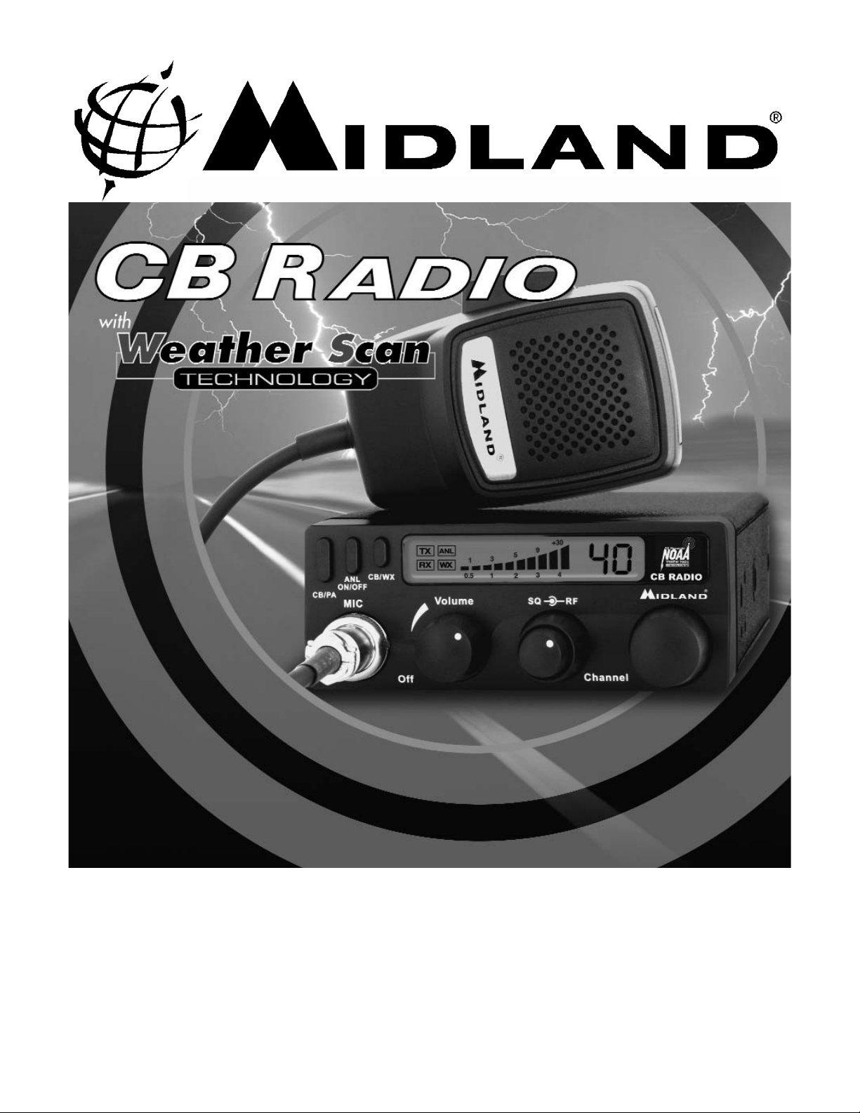
1001LWX Front Panel Features and Operation
1001LWX Front Panel Features and Operation
ON/OFF Volume Knob: In the off position your transceiver power is off. Turn this control clockwise to switch on the unit
and adjust the volume.
Micr
ophone Connector: Plug in the supplied microphone to this connector. Received signals will not be heard without the
microphone.
CB/P
A Button: When in PA mode, it causes your voice to operate the optional external PA speaker. In CB mode, the
microphone operates the transmitter.
ANL ON/OFF B
utton: Press this button once to activate the automatic noise limiter. When in ANL mode, ignition noise will
be reduced. Press the button again to deactivate ANL.
Weather(WX) Scan/CB But
ton: Press this button once to activate the weather scan. The radio will begin scanning and
lock on the first weather channel broadcast signal strong enough to use. If later the signal becomes too weak to use the
unit will automatically resume scanning to find a usable signal. The user can also make the unit scan to another channel
by pressing the microphone PTT button. The unit will rescan channels each time the CB/WX button is used to listen to
weather. When the radio is in weather scan mode, the user cannot use the CB/PA function.
S
quelch Control: This control is used to cut off or eliminate receiver background noise in the absence of an incoming signal. For maximum receiver sensitivity it is desired that the control be adjusted only to the point where the receiver background noise or background noise is eliminated. Adjust until the receiver noise disappears. This will require the incoming
signal to be slightly stronger than the average receiver noise. Further clockwise rotation will increase the threshold level
which a signal must overcome in order to be heard. Only strong signals will be heard at a maximum clockwise setting
RF Gain: This control is used primarily to optimize reception in strong signal areas. Gain is reduced by counter clockwise
rotation of the control.
Channel Knob:
This knob selects any one of the 40 Citizens Band channels. The selected channel is indicated by the LED
readout, directly above the Channel Knob.
Mic Connector
CB/PA Button
ANL ON/OFF
Button
WX Scan/CB
Button
ON/OFF
Volume Knob
Squelch Control
Knob
Channel Knob
Easy to Read
Backlit LCD
RF Gain Knob
Page 8

Model 1001LWX Owner’s Manual
Page 8 www.midlandradio.com
Back Panel Features and Operation
Back Panel Features and Operation
Antenna Connector: Connect a standard 50-ohm CB antenna to this connector.
External Speak
er Jack: When a speaker is connected to this jack, the internal speaker is
by-passed. All received signals will be heard through the external speaker. The speaker
connected to the “EXT” jack should be rated at 8 ohms and 5 watts.
P
A Jack: An optional PA speaker may be attached to your transceiver through the PA output jack on the back panel. This allows you to communicate with pedestrians or other
vehicles through your CB microphone. The speaker connected to the “PA” jack should be
rated at 8 ohms and 5 watts.
DC 13.8V POWER Cor
d: Connects to power cord with in line 2 Amp fuse.
How to Operate your Transceiver:
How to Operate your Transceiver:
You should become familiar with the controls and complete the preceding installation
instructions before attempting to operate your CB.
1. Rotate the on/off volume control clockwise to turn the unit on.
2. Adjust the squelch control fully counter-clockwise so noise is heard.
3. Adjust the volume for a normal listening level.
4. Rotate the squelch control until the noise just disappears.
5. Select the desired channel by rotating the channel selector.
6. To transmit, press the PTT bar on the side of the microphone. Hold the microphone
2 to 3 inches from your lips and speak in a normal voice.
7. To receive, simply release the PTT bar.
Warning: Do not attempt to make any internal adjustments. Internal adjustments and/or
modifications can lead to illegal operation as defined by the FCC rules and regulations, Part
95. They must be made only by qualified technical personnel. Illegal operation can lead to
serious consequences.
DC 13.8V Power
Cord
PA Jack
External Speaker
Jack
Antenna
Connector
Page 9

Model 1001LWX Owner’s Manual
Page 9
www.midlandradio.com
Technical Specifications
Technical Specifications
General
Frequency range ................................................................................26.965-27.405 MHz
Channels ....................................................................................................................40
Modulation type .........................................................................................................AM
Antenna impedance ............................................................................................50 Ohm
Loudspeaker .........................................................................................................8 Ohm
Microphone ........................................................................................1000 ohm..Electret
Power Supply ...........................................................................13.8 VDC negative ground
Size …………………………………………………….......................4-7/8"(W) x 6-1/2"(D) x 1-1/2"(H)
Unit Weight……………………………………………………………………..............................1 lb. 10 oz.
CB Receiver (26.965-27.405 MHz-)
Sensitivity at 10dB S/N...........................................................................................0.8 uV
Selectivity ...............................................................................................45 dB + 10 kHz
Squelch range .........................................................................................0.8 uV-1000 uV
Audio output power ......................................................3.0 W @ 8 Ohm ( 10% distortion)
Distortion at 1000 mV ................................................................................................3%
Audio frequency response ............................................................................400-2400 Hz
Intermediate frequency ...........................................................I ° 10.7 MHz II ° 455 kHz
Spurious response .................................................................................more than 40 dB
Transmitter
RF Output Power ...................................................................................................4.0 W
Frequency Tolerance ...........................................................................................0.005%
Harmonic Suppression ............................................................................More than 60 dB
Modulation ...........................................................................................AM 90% ( ± 5%)
Weather Receiver (162.400-162.550 MHz)
Sensitivity at 12dB S/N...........................................................................................0.4 uV
Spurious response .................................................................................more than 40 dB
Channel
Frequency
Channel 1 162. 400
Channel 2 162. 425
Channel 3 162. 450
Channel 4 162. 475
Channel 5 162. 500
Channel 6 162. 525
Channel 7 162. 550
Page 10

Model 1001LWX Owner’s Manual
Page 10 www.midlandradio.com
Service
Service
If it ever becomes necessary to return your unit for service:
Pack the unit in its original box and packing, improper packing may result in damage
during shipment. Be sure to remove the microphone from the radio before packing.
Include a full description of any problems. Include a daytime telephone number in the
event we need more information.
You do not need to return accessory items (brackets, screws, power cord, antenna, etc.)
unless they may be directly related to the problem.
Include a photocopy of the bill of sale or other proof of purchase showing the date of
sale (credit card statements are not acceptable). This information must be included
before warranty service can be considered.
A flat rate charge of $45 will apply to radios not covered by the Warranty. Master Card,
Visa, Cashier's Check or Money Order will be accepted for payment only. Personal checks
will not be accepted and will delay the repair of your radio until we receive payment by
approved methods.
Midland Radio Corporation
Hereby certifies that this unit has
been designed, manufactured,
FCC type accepted and certified
in accordance with part 95 and
Part 15, Subpart C of the current
FCC rules and regulations as of
the date of manufacture.
Page 11

Model 1001LWX Owner’s Manual
Page 11 www.midlandradio.com
Limited Warranty
Limited Warranty
Midland Radio Corporation will repair or replace, at its option without charge this model
1001LWX Citizens Band transceiver that fails due to a defect in material or workmanship
within three years following the initial consumer purchase.
This warranty does not include any accessories, which may be a part of or included with
the warranted product, or the cost of labor for removal or re-installation of the product
in a vehicle or other mounting.
Performance of any obligation under this warranty may be obtained by returning the
warranted product, freight prepaid, along with proof of purchase date, to Midland Radio
Corporation , Warranty Service Department, 5900 Parretta Drive, Kansas City, Missouri
64120, or to any "Midland Authorized Warranty Service Station", or to the place of purchase (if a participating dealer). This warranty gives you specific legal rights and you
may also have other rights which vary from state to state.
Note: The above warranty applies only to merchandise purchased in the United States
of America or any of the territories or possessions thereof, or from a U.S. Military
exchange. For warranty coverage on merchandise purchased elsewhere, consult the
supplemental warranty information included with this product or ask your dealer.
MIDLAND RADIO CORPORATION
5900 Parretta Drive
Kansas City, MO 64120
Phone 816-241-8500
E-mail: mail@midlandradio.com
www.midlandradio.com
Printed in China
Page 12

Model 1001LWX Owner’s Manual
Page 12 www.midlandradio.com
Accessories
Accessories
Accessories can be purchased at www.midlandradio.com or fill in the form on the following
page and mail to our address.
18-2442
18-2442
CENTER LOAD MAGNETIC MOUNT MOBILE
CB ANTENNA
•
Center loaded with 17-7 stainless steel whip
•
Relief spring for minimizing whip damage
•
Plastic-coated base to prevent rust
•
Prewired, includes cable, connector
•
$17.99
CB EXTENSION SPEAKER
•
3" Dynamic speaker with switchable noise
filter
•
8-ohm
•
Swivel base
•
5-foot cable with plug
•
$19.99
18-258
18-258
WINDOW MOUNT 27 MHz CB ANTENNA
•
Special process transfers energy from one side
of glass to the other without the need of
wires.
•
Simple to install
•
Rod is 17-7 stainless steel with new BLACK-
KOTE finish
•
$19.99
21-404C
21-404C
Page 13

Page 13 www.midlandradio.com
Model 1001LWX Owner’s Manual
18-2442
$17.99
18-258
$19.99
21-404C
$19.99
Page 14

 Loading...