

miniDSP Ltd, Hong Kong / www.minidsp.com / Features and specifications subject to change without prior notice 1
C-DSP 8X12
8-IN 12-OUT ADVANCED IN-CAR AUDIO PROCESSOR
User Manual
miniDSP Ltd, Hong Kong / www.minidsp.com / Features and specifications subject to change without prior notice 2
Revision history
Revision
Description
Date
V0.1
Preliminary version
15 February 2017
V0.2
Corrected specifications
16 February 2017
V0.3
REW at 192 kHz info
20 February 2017
V0.4
Revised preliminary based on 1.0 plugin
14 May 2107
V1.0
First release version for 1.0 plugin
22 May 2017

miniDSP Ltd, Hong Kong / www.minidsp.com / Features and specifications subject to change without prior notice 3
CONTENTS
Important Information ...............................................................................................................................................5
System Requirements .............................................................................................................................................5
Disclaimer/Warning ................................................................................................................................................5
Warranty Terms ......................................................................................................................................................6
FCC Class B Statement ............................................................................................................................................6
CE Mark Statement .................................................................................................................................................6
A note on this manual ............................................................................................................................................6
1 Product Overview ................................................................................................................................................7
1.1 Typical usage ..............................................................................................................................................7
1.2 The miniDSP concept ..................................................................................................................................8
1.3 Plugin feature summary .............................................................................................................................8
2 The miniDSP workflow .........................................................................................................................................9
3 Software installation ......................................................................................................................................... 11
3.1 Windows .................................................................................................................................................. 11
3.2 Mac .......................................................................................................................................................... 12
4 Hardware connectivity ...................................................................................................................................... 13
4.1 Analog inputs ........................................................................................................................................... 13
4.1.1 Low-level inputs ............................................................................................................................... 13
4.1.2 High-level inputs .............................................................................................................................. 14
4.2 Digital input ............................................................................................................................................. 15
4.3 Analog outputs ........................................................................................................................................ 15
4.4 DC power ................................................................................................................................................. 16
4.4.1 Powered on power (position 1) ....................................................................................................... 16
4.4.2 Remote trigger (position 2) ............................................................................................................. 16
4.5 Wired remote .......................................................................................................................................... 17
4.6 USB .......................................................................................................................................................... 17
5 Configuring the processor ................................................................................................................................. 18
5.1 Synchronizing with the processor ........................................................................................................... 18
5.2 Master mute ............................................................................................................................................ 19
5.3 Subwoofer and Master volume ............................................................................................................... 20
5.3.1 To select the channels controlled in Subwoofer Volume mode ..................................................... 20
5.3.2 To change the volume control mode .............................................................................................. 20
5.4 Inputs tab ................................................................................................................................................. 21
5.4.1 Digital input selection ...................................................................................................................... 21
5.4.2 Input channel strips ......................................................................................................................... 22
5.5 Routing tab .............................................................................................................................................. 23
5.5.1 Mixing channels ............................................................................................................................... 23
5.5.2 Routing to multiple outputs ............................................................................................................ 24
5.5.3 Cross-point gain and inversion ........................................................................................................ 25
5.6 Output tabs .............................................................................................................................................. 26
5.6.1 Channel strip layout ......................................................................................................................... 27

miniDSP Ltd, Hong Kong / www.minidsp.com / Features and specifications subject to change without prior notice 4
5.6.2 Channel label ................................................................................................................................... 27
5.6.3 Level meter and gain control ........................................................................................................... 27
5.6.4 Parametric EQ .................................................................................................................................. 28
5.6.5 Crossover ......................................................................................................................................... 30
5.6.6 Compressor ...................................................................................................................................... 32
5.6.7 Time delay ....................................................................................................................................... 33
5.6.8 Invert and mute ............................................................................................................................... 33
5.7 Custom biquad programming .................................................................................................................. 34
5.7.1 What’s a “biquad? ........................................................................................................................... 34
5.7.2 Using custom biquad programming ................................................................................................ 34
5.7.3 Biquad design software ................................................................................................................... 36
5.8 Working with configurations ................................................................................................................... 37
5.8.1 Online and offline mode .................................................................................................................. 37
5.8.2 Selecting a configuration ................................................................................................................. 37
5.8.3 Saving and loading configurations ................................................................................................... 38
5.8.4 Loading configurations from microSD card ..................................................................................... 38
5.8.5 Restoring to defaults ....................................................................................................................... 39
5.9 Keyboard shortcuts ................................................................................................................................. 39
5.10 Remote trigger timing ............................................................................................................................. 40
6 Using the C-DSP 8x12 ........................................................................................................................................ 41
6.1 Status indicators ...................................................................................................................................... 41
6.2 Controls ................................................................................................................................................... 41
6.3 Infrared remote control........................................................................................................................... 42
7 Additional information ...................................................................................................................................... 43
7.1 Specifications ........................................................................................................................................... 43
7.2 Input sensitivity setting ........................................................................................................................... 44
7.3 Troubleshooting ...................................................................................................................................... 45
7.4 Obtaining support .................................................................................................................................... 46

miniDSP Ltd, Hong Kong / www.minidsp.com / Features and specifications subject to change without prior notice 5
IMPORTANT INFORMATION
Please read the following information before use. In case of any questions, please contact miniDSP via the
support portal at minidsp.desk.com.
SYSTEM REQUIREMENTS
To configure the miniDSP audio processor, you will require a Windows PC or Apple Mac OS X computer with the
following minimum specification:
Windows
• PC with 1GHz or higher processor clock speed. Intel® Pentium®/Celeron® family, or AMD K6®/AMD
Athlon®/AMD Duron® family, or compatible processor recommended.
• 512 megabytes (MB) of RAM or higher
• Keyboard and mouse or compatible pointing device
• USB 2.0 port
• Microsoft• ® Windows® Vista® SP1/ XP pro SP2/Win7/Win8.1/Win10
• Microsoft• ® .NET framework v3.5 or later
• Adobe AIR environment (latest version)
• Adobe Flash player (latest version)
Mac OS X
• Intel-based Mac with 1 GHz or higher processor clock speed
• 512 megabytes (MB) of RAM or higher
• Keyboard and mouse or compatible pointing device
• USB 2.0 port
• Mac OS X 10.8 or higher
• Adobe AIR environment (latest version)
• Adobe Flash player (latest version)
DISCLAIMER/WARNING
miniDSP cannot be held responsible for any damage that may result from the improper use of this product or
incorrect configuration of its settings. As with any other product, we recommend that you carefully read this
manual and other technical notes to ensure that you fully understand how to operate this product. The miniDSP
audio processor is a powerful tool, and misuse or misconfiguration, such as incorrectly set gains or excessive
boost, can produce signals that may damage your audio system.
As a general guideline, you should perform the initial configuration of the miniDSP audio processor before
enabling audio through any connected output device or amplification. Doing so will help ensure that the
software is correctly configured.

miniDSP Ltd, Hong Kong / www.minidsp.com / Features and specifications subject to change without prior notice 6
Finally, note that the miniDSP audio processor is a very flexible device, and many of the questions we receive at
the tech support department are already answered in this user manual and in the online application notes on
the miniDSP.com website. So please take the time to carefully read this user manual and the online technical
support. Thanks for your understanding!
WARRANTY TERMS
miniDSP Ltd warrants this product to be free from defects in materials and workmanship for a period of one
year from the invoice date. Our warranty does not cover failure of the product due to incorrect connection or
installation, improper or undocumented use, unauthorized servicing, modification or alteration of the unit in any
way, or any usage outside of that recommended in this manual. If in doubt, contact miniDSP prior to use.
FCC CLASS B STATEMENT
This device complies with Part 15 of the FCC Rules. Operation is subject to the following two conditions:
• This device may not cause harmful interference.
• This device must accept any interference received, including interference that may cause undesired
operation.
Warning: This equipment has been tested and found to comply with the limits for a Class B digital device,
pursuant to Part 15 of the FCC Rules. These limits are designed to provide reasonable protection. This
equipment generates, uses and can radiate radio frequency energy and, if not installed and used in accordance
with the instructions, may cause interference to radio communications. However, there is no guarantee that
interference will not occur in a particular installation. If this equipment does cause harmful interference to radio
or television reception, which can be determined by turning the equipment off and on, the user is encouraged to
try to correct the interference by one or more of the following measures:
• Reorient or relocate the receiving antenna.
• Increase the separation between the equipment and receiver.
• Connect the equipment into an outlet on a circuit different from that to which the receiver is connected.
• Consult the dealer or an experienced radio/TV technician for help.
Notice: Shielded interface cable must be used in order to comply with emission limits.
Notice: Changes or modification not expressly approved by the party responsible for compliance could void the
user’s authority to operate the equipment.
CE MARK STATEMENT
The C-DSP 8x12 has passed the test performed according to European Standard EN 55022 Class B.
A NOTE ON THIS MANUAL
This User Manual is designed for reading in both print and on the computer. If printing the manual, please print
double-sided. The embedded page size is 8 ½” x 11”. Printing on A4 paper will result in a slightly reduced size.
miniDSP Ltd, Hong Kong / www.minidsp.com / Features and specifications subject to change without prior notice 7
1 PRODUCT OVERVIEW
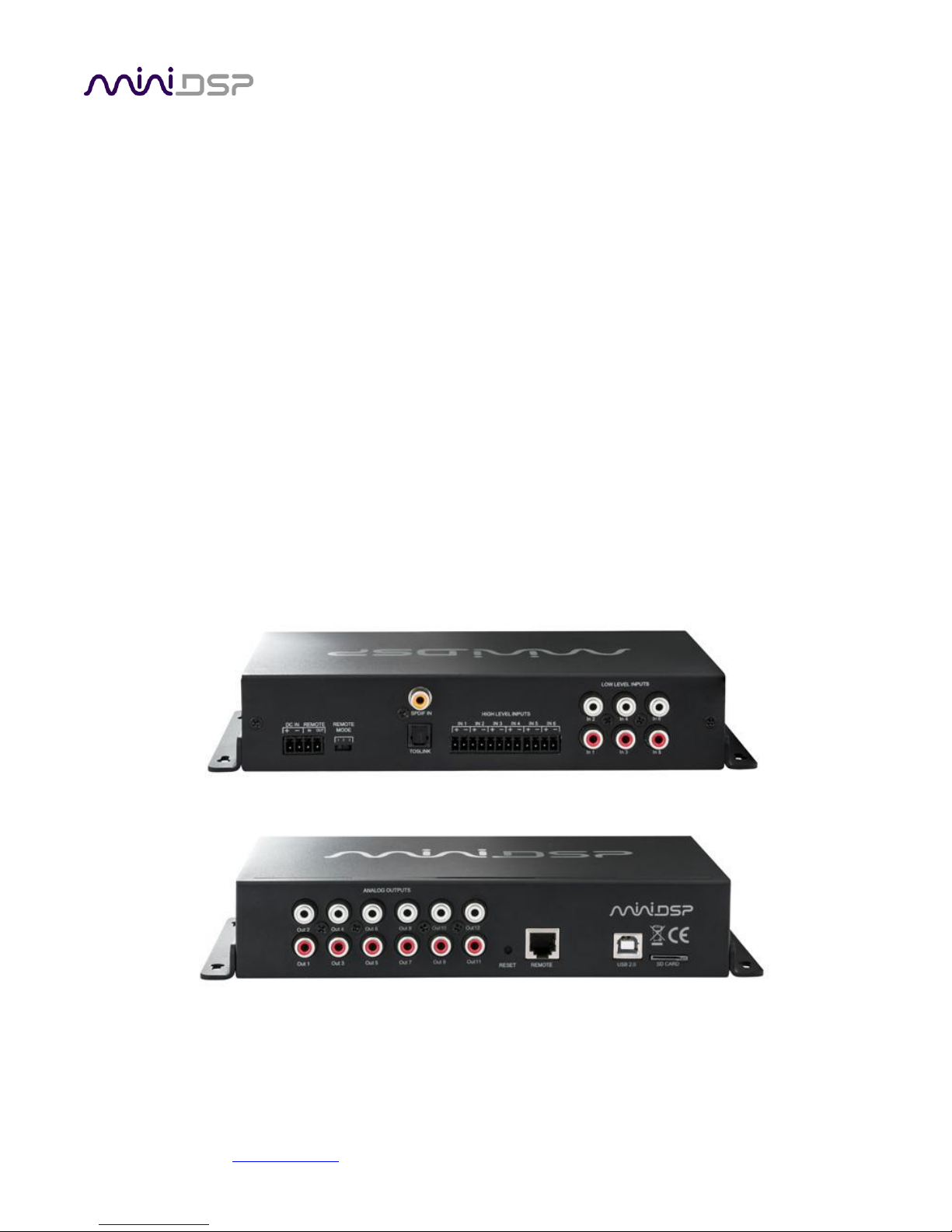
Thank you for choosing the miniDSP C-DSP 8x12 advanced in-car audio processor. The C-DSP 8x12 features an
onboard isolated power supply, stereo digital inputs (x2), 6 analog inputs, 12 analog outputs, and miniDSP’s
powerful but easy-to-use audio processing:
• Butterworth and Linkwitz-Riley crossovers up to 48 dB/octave
• Ten bands of parametric EQ (peaking/high shelf/low shelf/all pass) on every input and output channel
• Advanced biquad programming for an unlimited range of filters and crossover types
• An advanced matrix mixer for routing and mixing of any input to any output, with individual gain control and
inversion at every mixing cross-point
• Compression, time delay and level adjustment on every output channel
Four complete processing configurations are stored on-board and can be selected from the wired remote or by
infrared remote control.
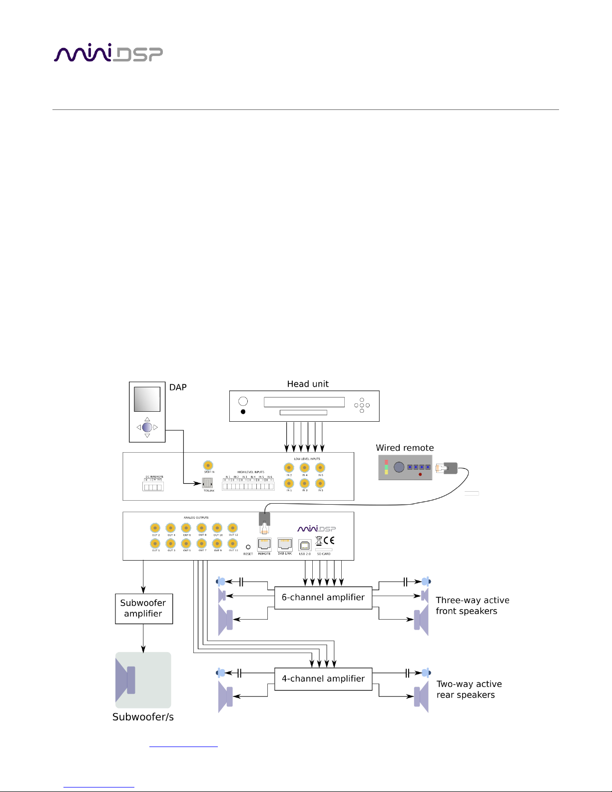
1.1 TYPICAL USAGE
The C-DSP 8x12 typically connects to a head unit with up to six output channels and directly drives power
amplifiers for multiple loudspeakers or drivers.

miniDSP Ltd, Hong Kong / www.minidsp.com / Features and specifications subject to change without prior notice 8
1.2 THE MINIDSP CONCEPT
The miniDSP concept is “one hardware unit + one software plugin = audio processing solution.” This concept
leverages the inherent flexibility of DSP (digital signal processing) to deliver a range of flexible but cost-effective
solutions.
Hardware unit
In this case, the hardware unit is the miniDSP C-DSP 8x12.
Software plugin
The software plugin is installed on your PC or Mac, and determines the processing that the DSP will
perform. It provides a friendly user interface, and downloads instructions into the miniDSP hardware
unit that tell it how to process the audio signal. Currently, the C-DSP 8x12 supports a single plugin (see
below).
Other platforms
miniDSP makes many other boxed and kit hardware units with analog, stereo digital, and multichannel
digital (HDMI) connections. Some units feature inbuilt Class D amplification. See the full range of
miniDSP products.
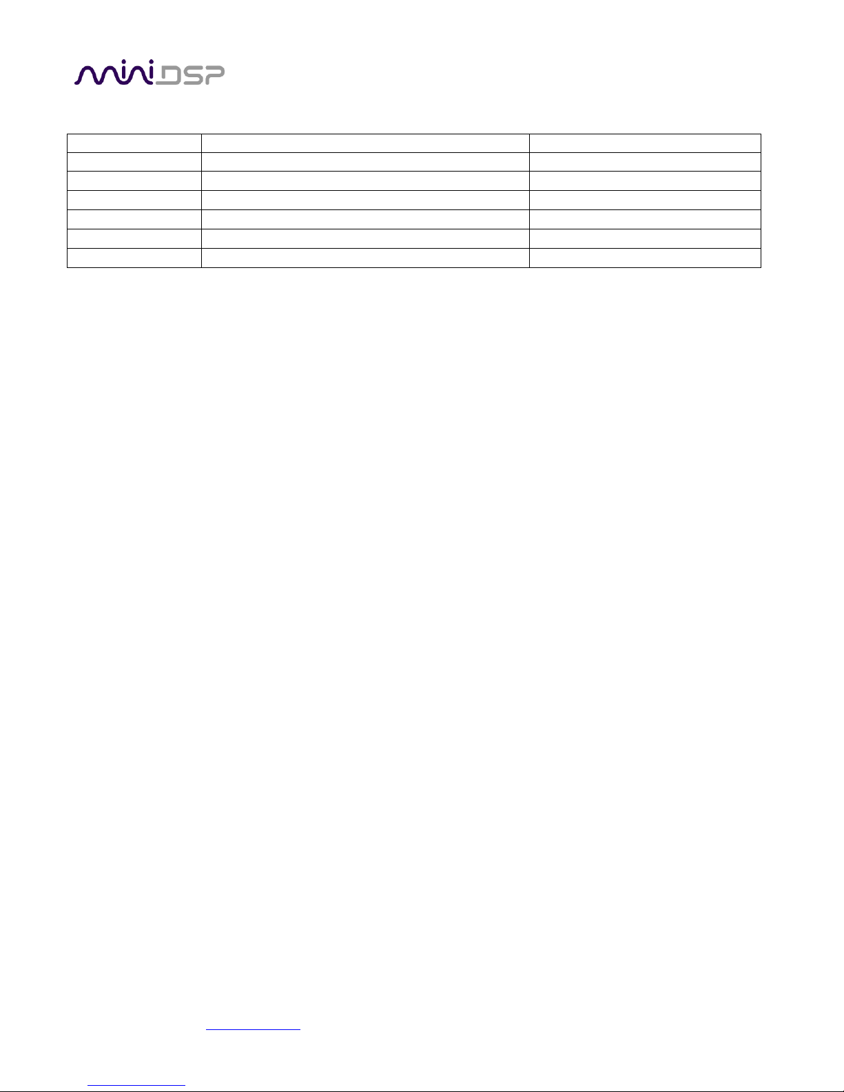
1.3 PLUGIN FEATURE SUMMARY
The table below summarizes the key features of the C-DSP 8x12 plugin:
C-DSP 8x12 plugin
Number of digital input channels*
2
Number of analog input channels
6
Number of analog output channels
12
Digital input sample rate
44.1 to 192 kHz
Internal sample rate
192 kHz
PEQ bands per input channel
10
PEQ bands per output channel
10
Crossover order
6 to 48 dB/octave
Compressor on each output channel
Yes
Maximum per-channel time delay
25 ms
(*) Two selectable stereo digital inputs, 1 x RCA and 1 x TOSLINK.
miniDSP Ltd, Hong Kong / www.minidsp.com / Features and specifications subject to change without prior notice 9
2 THE MINIDSP WORKFLOW
We strongly recommend taking a methodical approach to your new miniDSP audio processor. Remember that
the audio processor is a powerful tool, and incorrect settings can potentially cause damage to your system.
Please follow the steps below carefully.
1. Download and install the plugin
Download and install your plugin, as described in Software installation starting on page 9.
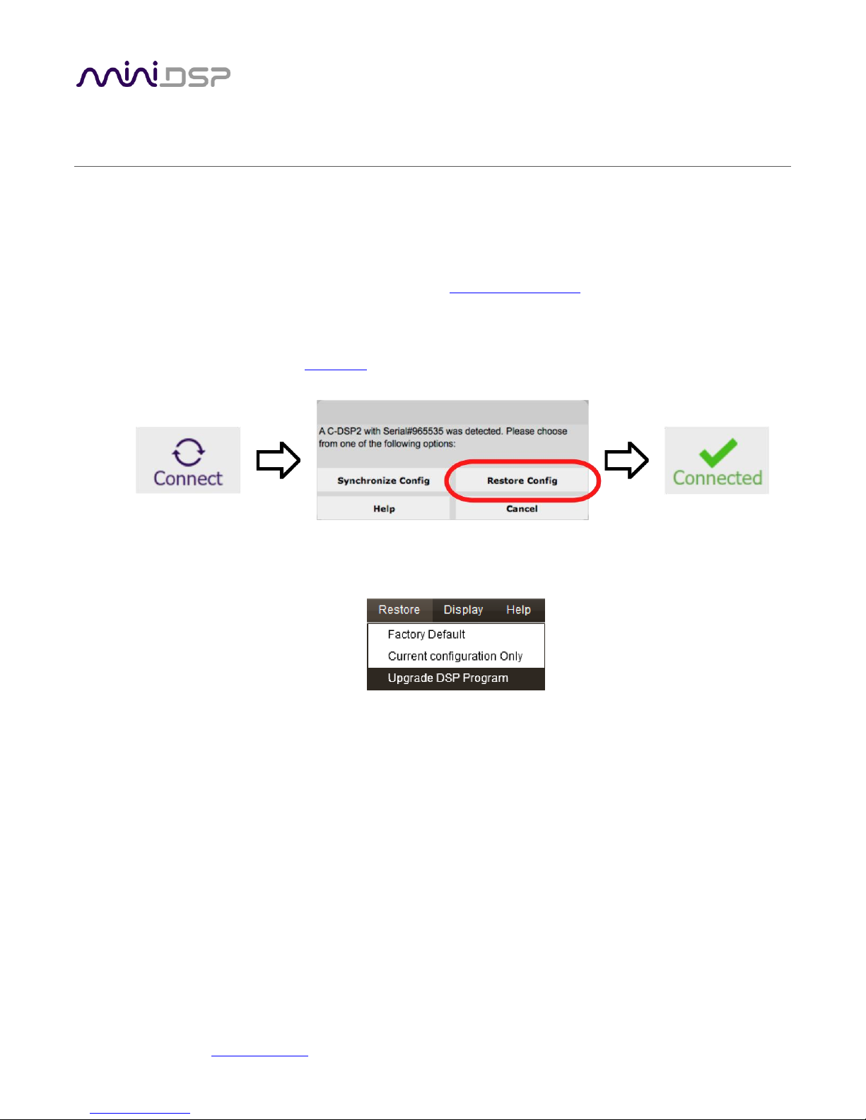
2. Synchronize and reset
Don’t connect any audio hardware to the processor yet. Connect the processor to the computer via
USB and apply power (see DC power on page 16). Start the plugin and click on the Connect button
near the top right. When the synchronization dialog comes up, click the Restore Config button.
3. Upgrade the DSP program
Drop down the Restore menu and select Upgrade DSP program. This ensures that the DSP processor in
the C-DSP 8x12 is running the latest software that matches your installed plugin.
4. Familiarize yourself with the plugin
At this point, the plugin is online – that is, any changes made in the computer user interface will be
immediately downloaded to the C-DSP. Familiarize yourself with the user interface presented by the
plugin. Click on and explore each of the tabs (Inputs, Routing, and Outputs). Feel free to experiment.
After you are done exploring, drop down the Restore menu and select the Factory Default option. This
will reset all processing parameters back to the defaults.
5. Perform initial configuration
Use the plugin to set up an initial audio processing configuration as intended for your application. (See
Section 5 for details.) Typical things that can be done at this point are to:
• Set the labels of input and output channels
• Mute unused input and output channels
• Set routing, crossover frequencies and slopes
• Set up any essential equalization
miniDSP Ltd, Hong Kong / www.minidsp.com / Features and specifications subject to change without prior notice 10
6. Save your configuration
Save your initial configuration to a file. A configuration is the set of all audio processing parameters.
For more information on configurations, see Working with configurations starting on page 37.
7. Make audio connections
Remove power from the processor.
Now connect the miniDSP C-DSP 8x12 into your system. See Hardware connectivity starting on page 13
for details. Ensure that all power is turned off when making audio connections.
8. Go online
Apply power to the processor. (Leave other equipment turned off at this stage.) Connect the USB cable
to your computer, click on the Connect button, and select the Synchronize Config option. If all goes
well, you are now in online mode – any changes that you make in the plugin user interface will be
immediately sent to the processor.
Before proceeding, click on each Configuration preset button (Config 1, 2, etc.) to ensure that all
presets have been synchronized.
9. Initial audio check
1. Power on your connected equipment, first on the input side (e.g. head unit), then on the output
side (e.g. power amps).
2. Turn the volume on your C-DSP 8x12 down low (view the Master Volume display in the plugin
while turning the knob on the wired remote counter-clockwise) and start playing music or a pink
noise test signal.
3. Gradually increase the volume until you hear audio quietly coming from the speakers.
4. Verify that the plugin is performing the intended function. (For example, for a two-way crossover,
confirm that the tweeter plays high frequencies and the woofer plays low frequencies.)
10. Fine-tune your configuration
With your initial setup running, you can now proceed to fine-tune and optimize your system. You will
need to perform acoustic measurements and use the configuration screens to adjust processing
parameters.
Save your configuration on a regular basis while working on fine-tuning it. Configurations can be saved
to different files to archive different versions and to enable auditioning of alternative configurations.
Regular saving will also help ensure that you do not lose your work if you inadvertently reset the
processor to default settings.
11. Continue to operate offline
With the processor configured, you can continue to operate in offline mode—that is, without the
computer connected. To do so, quit the plugin or disconnect the USB cable. The processor will
continue to operate without the computer.
Note: you can still change settings in the plugin user interface while in offline mode – these will be
synchronized back to the processor next time you connect and select the Synchronize Config option.
miniDSP Ltd, Hong Kong / www.minidsp.com / Features and specifications subject to change without prior notice 11
3 SOFTWARE INSTALLATION
If you purchased your product directly from miniDSP, your software will be available from the User Downloads
section of the miniDSP website when your order ships.
If you purchased your product from a miniDSP dealer, you will receive a coupon together with the product.
Redeem this coupon and select the Plugin Group “CDSP 8x12” at the link below:
• https://www.minidsp.com/support/redeem-coupon
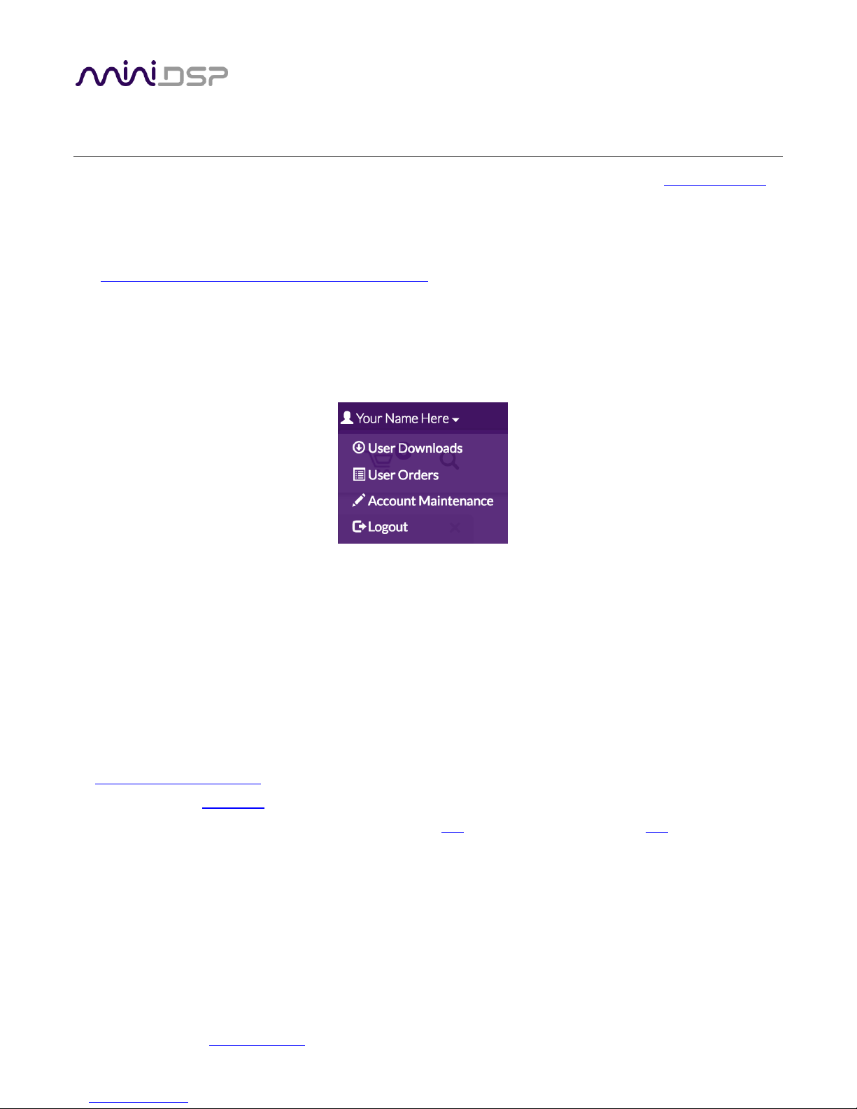
To access the download, you will need to be logged into the miniDSP.com website with the account you created
when purchasing. The User Downloads link is visible from the dropdown menu at the top right of the website
page:
Navigate to the C-DSP plug-ins section and download the zip file under the heading C-DSP 8x12 plugin. Unzip
the downloaded file: on Windows, right-click and select “Extract All...”; on Mac, double-click.
3.1 WINDOWS
The miniDSP software requires that other frameworks are installed for it to work. For Windows 7 and later,
these packages should be installed automatically by the miniDSP installer.
For Windows XP and Vista, please download and install the following frameworks before attempting to install
any miniDSP software:
• Microsoft .NET framework (version 3.5 or later)
• Latest version of Adobe Air
• Microsoft Visual C++ 2010 Redistributable Package: for x86 (32-bit operating system) or x64 (64-bit operating
system)
To install the plugin:
1. Navigate to the Windows folder of the software download.
2. Double-click on the C-DSP-8x12.exe installer program to run it. We recommend that you accept the default
installation settings.
3. The plugin will start automatically if you accepted the default installation settings. To make it quicker to run
in future, right-click on its icon in the taskbar and select “Pin to taskbar.”
miniDSP Ltd, Hong Kong / www.minidsp.com / Features and specifications subject to change without prior notice 12
Note 1: The Adobe Air framework may need to connect to the Internet the first time you run the plugin.
Note 2: The first time you run the plugin, you may see a warning from Windows Firewall asking whether the
software should be allowed network access. If you do, ensure that “Private networks...” is checked and “Public
networks...” is not checked. Then click on “Allow access.”
3.2 MAC
To install the plugin:
1. Navigate to the Mac folder of the software download.
2. The installer program is named C-DSP-8x12.pkg. To run it, double-click on it, or right-click and open as
described below. We recommend that you accept the default installation settings.
3. To run the plugin, locate C-DSP-8x12.app in the Applications -> miniDSP folder and double-click on it. To
make it easier to run in future, right-click on its dock icon and select Options -> Keep in Dock.
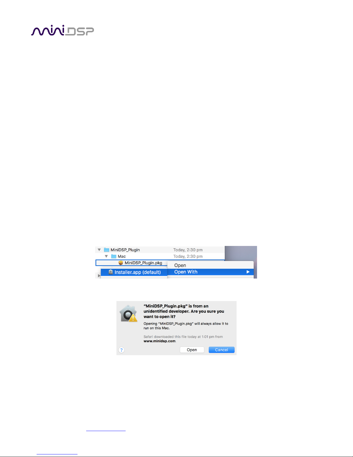
Note 1: If double-clicking on an installer brings up a message that the installer cannot run, use this alternate
method (note that the name of the plugin will be C-DSP-8x12.pkg, not MiniDSP_Plugin.pkg as shown in the
screenshots):
1. Right-click on the installer (or click while holding the Control key).
2. On the menu that pops up, move the mouse over the “Open With” item and then click on “Installer
(default).”
3. The following window will appear. Click on “Open.”
Note 2: The Adobe Air framework may need to connect to the Internet the first time you run the plugin.
miniDSP Ltd, Hong Kong / www.minidsp.com / Features and specifications subject to change without prior notice 13
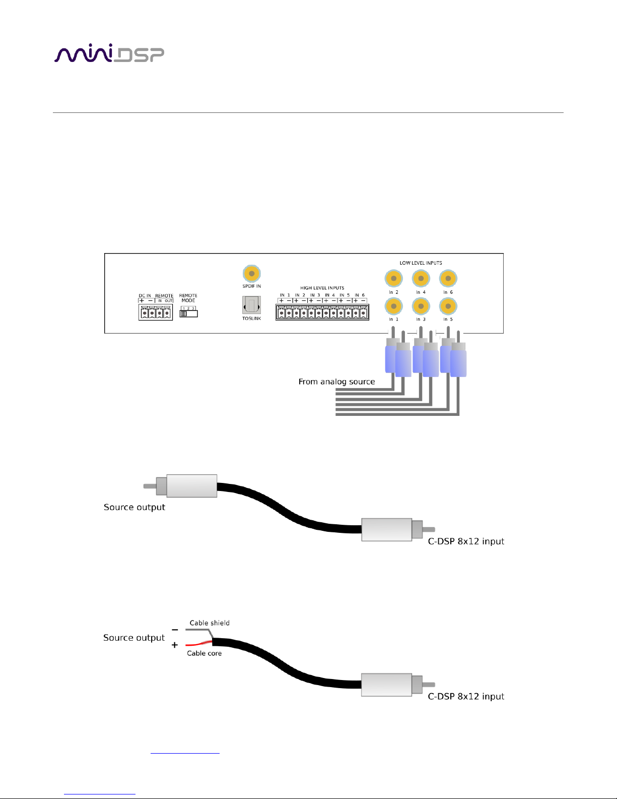
Figure 1. Single-ended RCA connection
Figure 2. Connecting a balanced source to the C-DSP 8x12.
4 HARDWARE CONNECTIVITY
Connections to the C-DSP 8x12 are made on the front and rear panels.
4.1 ANALOG INPUTS
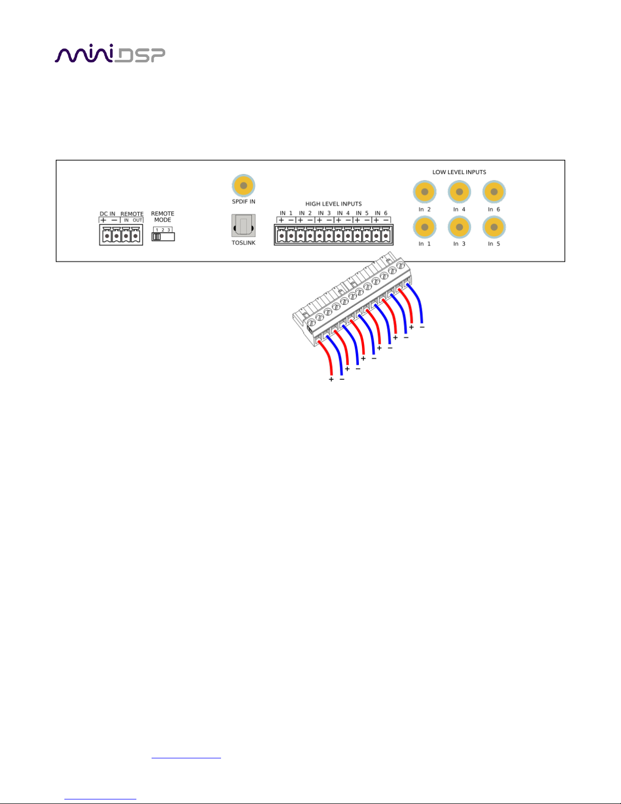
4.1.1 Low-level inputs
Low-level analog connections are made directly to the RCA jacks on the front panel. Be sure to take careful note
of the channel numbering shown in this diagram and on the front panel. These inputs accept a maximum input
voltage of either 2 or 4 VRMS, depending on the input sensitivity switch setting (see page 44).
Note that these are fully differential inputs. A regular RCA-RCA cable be used to connect from equipment with
single-ended outputs, as shown in Figure 1.
If connecting to equipment with balanced output, connect the negative or “cold” leg to the RCA shield and the
positive or “hot” leg to the RCA tip, as shown in Figure 2.
miniDSP Ltd, Hong Kong / www.minidsp.com / Features and specifications subject to change without prior notice 14
4.1.2 High-level inputs
High-level (speaker-level) connections can be made by connecting bare wire ends to the push-in terminal block.
Remove the terminal block, and connect individual positive and negative wires to each screw terminal. After all
connections are secure, firmly re-insert the terminal block.
The high-level inputs have an input impedance of 68 Ω and are designed for connection to power amplifier
outputs. The inputs are fully differential, therefore:
• Amplifiers with bridged outputs can be used.
• Do not connect the “–” outputs together. This can potentially damage amplifiers.
The maximum (differential) input voltage is either 8 or 12 V RMS, depending on the input sensitivity switch
setting (see page 44). The 8 V RMS setting corresponds to a maximum amplifier power of 16 Watts into 4 ohms.
The 12 V RMS setting corresponds to a maximum amplifier power of 36 Watts into 4 ohms.

miniDSP Ltd, Hong Kong / www.minidsp.com / Features and specifications subject to change without prior notice 15
4.2 DIGITAL INPUT
Two digital sources can be connected via the S/PDIF coax (RCA) connector and the TOSLINK (optical) connector.
Switching between sources can be done from within the plugin or with a remote control.
The left and right channels of the selected digital input are mixed with the analog inputs as specified by the
cross-points on the Routing tab (page 23).
Note: the digital inputs accept only a stereo PCM digital signal. They do not accept encoded or multichannel
digital audio.
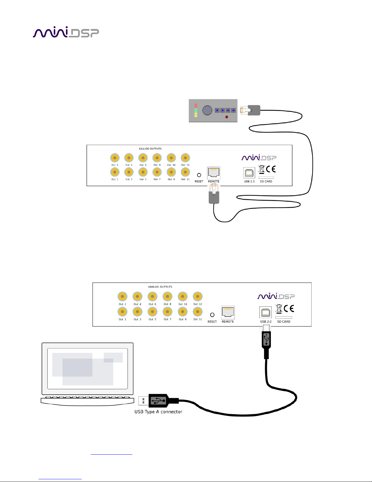
4.3 ANALOG OUTPUTS
There are twelve analog output channels. Unbalanced connections are made from the RCA jacks on the rear
panel to the power amplifiers. Be sure to take careful note of the channel numbering shown in this diagram and
on the rear panel.

miniDSP Ltd, Hong Kong / www.minidsp.com / Features and specifications subject to change without prior notice 16
4.4 DC POWER
The C-DSP 8x12 incorporates an isolated DC-DC power convertor and is designed for direct connection to the
vehicle's power supply (nominally 12 V DC). Power is connected via a four-way terminal block. There are two
modes of operation, described below.
4.4.1 Powered on power (position 1)
To power on the C-DSP 8x12 whenever 12 V DC is applied to the DC IN terminals, set the REMOTE MODE switch
to position 1. Typically, power is provided from the main vehicle supply (always on).
4.4.2 Remote trigger (position 2)
To reduce battery drain, the remote trigger option should be used. To enable remote trigger, set the REMOTE
MODE switch to position 2. In this case, the C-DSP 8x12 is powered on when the voltage on the REMOTE IN
terminal exceeds 4 V DC. Typically, REMOTE IN is connected to the remote trigger output from the head unit.
In this mode, the REMOTE OUT terminal should be used to turn on the power amplifier(s). There is a time delay
between REMOTE IN going positive and REMOTE OUT going positive. This can be configured in the plugin – see
page 40.
Position 3 of the REMOTE MODE switch is reserved for future use. Do not set the switch to position 3.
miniDSP Ltd, Hong Kong / www.minidsp.com / Features and specifications subject to change without prior notice 17
4.5 WIRED REMOTE
The wired remote can be positioned anywhere in the vehicle and is connected via the supplied RJ11 phone
cable. The plugs on each end simply plug into the base of the remote and into the rear panel of the C-DSP 8x12.
The wired remote also contains the receiver for infrared remote control.
4.6 USB
To configure the processor, connect its USB port to a USB 2.0 port on your computer using the supplied cable.
Note that USB is used only for configuration — audio data cannot be streamed to the processor over USB.

miniDSP Ltd, Hong Kong / www.minidsp.com / Features and specifications subject to change without prior notice 18
5 CONFIGURING THE PROCESSOR
The C-DSP 8x12 processor is configured with the C-DSP 8x12 plugin / user interface program. Once fully
configured, the computer is no longer required and the unit can be controlled with the wired remote or an
infrared remote control. If desired, however, the plugin can remain connected during use for real-time (“live”)
control of all audio processing.
This screenshot shows the C-DSP 8x12 plugin with the key areas highlighted:
During initial configuration of the processor, it is strongly recommended that any connected
amplification be muted or powered off.
5.1 SYNCHRONIZING WITH THE PROCESSOR
Communication with the C-DSP takes place over USB. Note that USB is used for control purposes only. Audio
data cannot be streamed to the processor over USB.
Ensure that the computer is connected to the processor via a USB 2.0 port. Then click on the Connect button:

miniDSP Ltd, Hong Kong / www.minidsp.com / Features and specifications subject to change without prior notice 19
The first time you connect, or if you have made any changes to any data in the user interface, the following
dialog box will appear:
The options are:
Synchronize Config
Download the currently selected configuration into the corresponding configuration preset of the
processor. After downloading the configuration data, the plugin is in online mode and any changes to
processing parameters will be downloaded immediately in real time. That is, the user interface is now
“live.”
Synchronize and Upgrade
This is similar to Synchronize Config, but also upgrades the internal data of the processor. This option
may appear after downloading and installing an updated version of the plugin.
Restore Config
Restore the data in the currently selected configuration to the factory defaults. When using this
option, any connected output equipment should be muted or powered off until you have set the
configuration to a working state. Note that the configuration data currently stored in the processor will
be deleted.
Cancel
This option cancels the attempt to connect to the processor. The plugin will remain in offline mode.
5.2 MASTER MUTE
The Mute button disables all audio output:

miniDSP Ltd, Hong Kong / www.minidsp.com / Features and specifications subject to change without prior notice 20
5.3 SUBWOOFER AND MASTER VOLUME
The C-DSP 8x12 has two modes of volume control operation:
• Master volume mode. In this mode, the wired remote and infrared remote control the master volume i.e.
all output channels.
• Subwoofer volume mode. In this mode, the wired remote and infrared remote control the volume of just a
selected set of channels. This is typically used to control subwoofer volume, but can also be used in other
ways – for example, to control rear channel speaker level.
The current values for master and subwoofer volume are displayed in the plugin while connected:
5.3.1 To select the channels controlled in Subwoofer Volume mode
Drop down the Display menu and select Subwoofer Channels Selection. In the dialog box, check the channels to
be controlled. Note that any number of channels can be selected.
5.3.2 To change the volume control mode
Open the Subwoofer Channels Selection dialog box. Use the dropdown labeled Selected Volume Mode to
select the desired mode.
The volume control mode can also be changed with the wired remote – see page 41.

miniDSP Ltd, Hong Kong / www.minidsp.com / Features and specifications subject to change without prior notice 21
5.4 INPUTS TAB
The Inputs tab displays a row of input channel control strips:
5.4.1 Digital input selection
When the plugin is connected to the C-DSP 8x12, the currently selected digital input appears above input
channel strips 7 and 8. Click on the current input name to drop down a selector menu, from which you can select
the input. (You can also select the digital input with an infrared remote control – see page 42.)
TOSLINK
Selects the stereo optical digital input.
SPDIF
Selects the stereo coax (RCA) digital input.
The left and right channels of the selected digital input are mixed with the analog inputs as specified by the
cross-points on the Routing tab (page 23).

miniDSP Ltd, Hong Kong / www.minidsp.com / Features and specifications subject to change without prior notice 22
5.4.2 Input channel strips
Channel label
Each input channel has a customizable label, which is shown at the top of the channel strip. This label
also appears on the Routing matrix. To change the label, click on it, type a new label (up to eight
characters), and press the Return key.
Level meter, Current RMS level
Displays the current signal level in real time. (The plugin must be in online mode to display signal
levels.)
Gain adjustment
The gain of each channel can be adjusted by moving the Gain Adjustment slider, or by typing the
desired gain into the Current Gain text box. The maximum gain setting is 12 dB and the minimum gain
setting is –72 dB. (0 dB, the default, is unity gain or no change in level.)
PEQ settings
Click on this button to open the parametric EQ settings window for that channel. There are ten
parametric EQ filters on each input channel. For more details, see Parametric EQ on page 28.
Mute
Press this button to mute that input channel. The button color and label changes to show that the
channel is muted.

miniDSP Ltd, Hong Kong / www.minidsp.com / Features and specifications subject to change without prior notice 23
5.5 ROUTING TAB
The Routing tab displays the matrix mixer, which sets up routing and mixing from input channels to output
channels. The input channels are labeled along the left and the output channels along the top. The labels that
appear along the left and the top can be changed on the Inputs and Outputs tabs.
The routing tab is the key to the extraordinary flexibility of the miniDSP C-DSP 8x12. This is the default routing
tab:
When a cross-point is turned on, the input signal (at the left) is routed to the output channel (at the top). In the
default routing, Input1 is routed to Output1, Input2 to Output2, and so on.
5.5.1 Mixing channels
If more than one input channel is routed to the same output channel, the input channels are mixed (summed
together). This can be used, for example, to mix multiple inputs to create a subwoofer feed. Here is a simple
example, with left and right input channels, left and right output channels, and one mono (mixed) subwoofer
output channel:
(This screenshot and the others in the rest of this section show just part of the routing matrix, with informative
labels set in the Inputs and Outputs tabs. The examples are simplified for the purposes of explanation.)
Typically, for an example like this, the left and right output channels will have a high pass filter set at around 80
Hz. The subwoofer output channel will have a low pass filter also set at around 80 Hz.

miniDSP Ltd, Hong Kong / www.minidsp.com / Features and specifications subject to change without prior notice 24
5.5.2 Routing to multiple outputs
Each input channel can be routed to multiple outputs. There is no limit – an input signal could be sent to all
twelve outputs if desired, with no effect on signal quality.
Example 1 – additional subwoofers
A simple example is shown on the previous page, where both inputs are sent both to the corresponding left or
right speaker channel and to the subwoofer channel. This example can easily be expanded by adding additional
subwoofer output channels.
Example 2 – active speakers
The C-DSP 8x12 can create complex active speaker systems. Each audio channel is routed to two or more output
channels. Here is an example for three-way speakers:
On the output channels, crossovers must be set up on the Xover screen (see page 30 for details):
• Woofer: low pass filter enabled
• Midrange: low pass and high filters enabled
• Tweeter: high pass filter enabled
To illustrate, this is the Xover screen for the midrange channel:
Usually, you will also link the crossover settings for the corresponding left and right channels: Woof L linked to
Woof R, Mid L to Mid R and so on.

miniDSP Ltd, Hong Kong / www.minidsp.com / Features and specifications subject to change without prior notice 25
5.5.3 Cross-point gain and inversion
At each cross-point, the gain of each signal being mixed can be set to a value between -72 and +12 dB. To set the
gain, right-click on the cross-point and a gain control will appear. Set the gain by moving the slider, or
alternatively, type the value in directly into the entry box below, press the Enter key, then click the close button.
Each cross-point can also have the signal inverted by clicking on the Invert button. When the mixed signal is
inverted, the button will be displayed in green and its label will change to “Inverted”.
The Invert button is useful in applications such as generating a difference signal for rear fill. If you want to try
this, experiment as follows:
1. Create L–R and R–L signals as shown in the matrix below.
2. Add a delay of about 20 ms to the rear channel outputs.
3. Add high pass and low pass filters to the rear channels to limit bandwidth (experiment to see what sounds
best).

miniDSP Ltd, Hong Kong / www.minidsp.com / Features and specifications subject to change without prior notice 26
5.6 OUTPUT TABS
There are two output tabs: one for channels 1 to 6 and one for channels 7 to 12. Each displays a row of output
channel control strips. All output channels are identical.

miniDSP Ltd, Hong Kong / www.minidsp.com / Features and specifications subject to change without prior notice 27
5.6.1 Channel strip layout
Each output channel has a complete "strip" of controls.
5.6.2 Channel label
Each output channel has a customizable label, which is shown at the top of the channel strip. This label also
appears on the Routing tab. To change the label, click on it, type a new label (up to eight characters), and press
the Return key.
5.6.3 Level meter and gain control
Level meter, current RMS level
Displays the current signal level in real time. (The plugin must be in online mode to display signal
levels.)
Gain adjustment
The gain of each channel can be adjusted by moving the Gain Adjustment slider, or by typing the
desired gain into the Current Gain text box. The maximum gain setting is 12 dB, and the minimum gain
setting is –72 dB. (0 dB, the default, is unity gain or no change in level.)
The level meters are useful in many situations. For example, when adding filters with boost, monitor the level
meters with typical signals and maximum levels to ensure that there is no clipping. The meters can also be used
during normal operation to monitor for or to help locate level or gain structure problems.
miniDSP Ltd, Hong Kong / www.minidsp.com / Features and specifications subject to change without prior notice 28
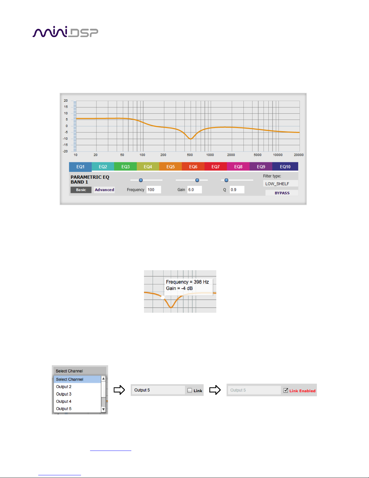
5.6.4 Parametric EQ
Parametric equalization (PEQ) is a flexible type of equalization filter. It can be used to correct for errors in
loudspeaker output, to compensate for acoustic room/cabin effects, and to tailor the overall system response
for best sound. Click on the PEQ button to open the parametric equalizer settings window:
There are 10 parametric EQ filters on each input and output channel. The window displays a frequency response
graph showing the combined response of all enabled filters on that channel. For example, the screenshot above
shows a response curve created with a low-shelf boost filter at 100 Hz, a dip at 500 Hz, and a high-shelf cut filter
at 5000 Hz.
Hovering the mouse over the curve brings up an overlay showing the frequency and the gain at that frequency.
Each channel can be linked to one other channel. When a channel is linked to another, the PEQ settings of that
channel are mirrored to the other. Typically, the corresponding drivers on the left and right channels are linked:
left and right tweeter, left and right woofer, and so on. To link a channel, select the other channel from the
drop-down menu at the top left of the PEQ screen, and click the Link checkbox.

miniDSP Ltd, Hong Kong / www.minidsp.com / Features and specifications subject to change without prior notice 29
EQ band selection
Click on the tabs EQ1, EQ2, etc. to display the parameters for that filter.
Basic/Advanced
By default, each filter is in basic mode and shows the controls described below. Advanced mode
enables custom biquad programming for almost infinite flexibility in filter implementation. This is
described in Custom biquad programming on page 34.
Filter type
Selects the type of filter:
PEAK Create a dip or a peak in the frequency response.
LOW_SHELF Reduce or increase part of the frequency spectrum below a given frequency.
HIGH_SHELF Reduce or increase part of the frequency spectrum above a given frequency.
ALL_PASS Create a phase shift across the frequency band. This can be useful for correcting phase
issues and for simulating analog crossovers.
Frequency
For the PEAK filter type, this is the center frequency of the peak or dip. For the HIGH_SHELF and
LOW_SHELF filter types, this is the frequency at which the gain is half of the set value. For the
ALL_PASS filter type, this is the center frequency of the phase shift.
Gain
For the PEAK filter type, this is the gain in dB at the center frequency. For the HIGH_SHELF and
LOW_SHELF filter types, this is the gain in dB reached at high or low frequencies respectively. A filter
has no effect if its gain is set to 0 dB. Gain can be adjusted in increments of 0.1 dB up to +/- 16 dB. This
item is not present for the ALL_PASS filter type.
Q
Q controls the “sharpness” of the filter. For the PEAK filter type, lower Q gives a broader peak or dip,
while higher Q gives a narrower peak or dip. For the HIGH_SHELF and LOW_SHELF filter types, Q
controls how quickly the filter transitions from no gain to maximum gain. For the ALL_PASS filter type,
higher Q gives a steeper phase transition.
Bypass
The Bypass button enables or disables a filter. The filter is enabled if the button says “BYPASS” and
disabled if the button says “BYPASSED” (see screenshot below). Note that this button only enables and
bypasses a single filter; all other filters must be bypassed or enabled individually.

miniDSP Ltd, Hong Kong / www.minidsp.com / Features and specifications subject to change without prior notice 30
5.6.5 Crossover
Each output channel has independent high pass and low pass crossover filters. Click on the Xover button to open
the crossover settings window:
Crossovers “split” the frequency band to send to different drivers. In a two-way loudspeaker, for example, a low
pass filter is used to remove high frequencies from the signal sent to the woofer, and a high pass filter is used to
remove low frequencies from the signal sent to the tweeter. In a three-way speaker, the midrange driver will
use both the high pass and low pass filters. Crossover filters can also be used to limit low frequency content
delivered to a speaker or subwoofer, to help protect it from over-excursion.
Unlike conventional analog crossovers, the flexibility of DSP allows a completely arbitrary mix of different filter
slopes and types. Filters can be set at any frequency, or disabled completely. This allows maximum flexibility in
matching your crossover to the acoustic characteristics of the loudspeaker drivers.
Hovering the mouse over the curve brings up an overlay showing the frequency and the attenuation at that
frequency.

miniDSP Ltd, Hong Kong / www.minidsp.com / Features and specifications subject to change without prior notice 31
Basic/Advanced
By default, the crossover is in basic mode and shows the controls described below. Advanced mode
enables custom biquad programming for almost infinite flexibility in crossover filter implementation.
This is described in Custom biquad programming on page 34.
Cutoff Frequency
Sets the nominal cutoff frequency of the crossover. In actual fact, the crossover has a more or less
gradual transition from “full on” to “full off,” as determined by the filter slope.
Filter type
Selects the type and slope of the filter. The steeper the slope, the more quickly frequencies above or
below the cutoff frequency are attenuated. There are three types of filter:
Butterworth (BW)
Available in 6, 12, 18, 24, 30, 36, 42, and 48 dB/octave, Butterworth crossover filters are 3 dB
down at the cutoff frequency.
Linkwitz-Riley (LR)
Available in 12, 24, and 48 dB/octave, Linkwitz-Riley crossover filters are 6 dB down at the cutoff
frequency.
Bessel
Available in 12 dB/octave only, a Bessel filter gives a more gradual roll-off through the crossover
region.
Bypass
The Bypass button enables or disables a crossover filter. The filter is enabled if the button says
“BYPASS” and disabled if the button says “BYPASSED” (see screenshot below).
Each channel can be linked to one other channel. When a channel is linked to another, the crossover settings of
that channel are mirrored to the other. Typically, the corresponding drivers on the left and right channels are
linked: left and right tweeter, left and right woofer, and so on. To link a channel, select the other channel from
the drop-down menu at the top left of the Xover screen, and click the Link checkbox.

miniDSP Ltd, Hong Kong / www.minidsp.com / Features and specifications subject to change without prior notice 32
5.6.6 Compressor
The compressor reduces the gain of an output channel when the audio signal exceeds the level specified by the
Threshold parameter. The gain of the channel will be progressively reduced as the signal increases above the
threshold, as specified by the Ratio parameter. This can be used to limit the power delivered to speakers and
thus reduce the risk of damage from overdriving.
This screenshot shows an example Compressor setting:
(Note that the compressor algorithm is bypassed by default, so click on the Bypass button to see the curve as
shown here.)
In this example, the threshold is set to -20 dB, so the compressor will activate when the signal on that channel
reaches -20 dB (relative to full output). The ratio is set to 2, so if the input signal level to the compressor then
increases by 10 dB, the output level will increase by only 5 dB. If the input signal level to the compressor is at full
scale (0 dB), then the output level will be limited to -10 dB.
Two additional parameters control the action of the compressor: the attack time and the release time. These
two parameters govern how quickly the compressor activates when the signal level exceeds the threshold, and
how quickly it deactivates when the signal level reduces. The optimum settings may need to be tuned by ear.
For more information, see the Wikipedia article Dynamic range compression.

miniDSP Ltd, Hong Kong / www.minidsp.com / Features and specifications subject to change without prior notice 33
5.6.7 Time delay
A delay of up to 25 ms can be applied to each output channel. To set the delay, click in the delay entry box for a
channel. The delay value can be entered numerically by typing in the entry box. The up and down arrows can be
used to change the delay in small increments.
The time delay corresponds to a distance. This distance is shown in cm when the cursor is hovered over the time
delay box. The maximum time delay of 25 ms corresponds to a distance of approximately 8.6 meters (about 28
feet).
The delay can also be displayed and entered directly in terms of its equivalent distance in cm. To do so, drop
down the Display menu and select Show Delay in cm unit.
In this case, hovering the cursor over the entry box will display the actual time delay:
5.6.8 Invert and mute
Each output channel can be inverted in polarity, and individually muted. When either of these options is
selected, the display changes color and the label of the button reflects the current state.

miniDSP Ltd, Hong Kong / www.minidsp.com / Features and specifications subject to change without prior notice 34
5.7 CUSTOM BIQUAD PROGRAMMING
Custom biquad programming is available in the PEQ and Xover (crossover) blocks. Its purpose is to allow you to
directly provide the low-level parameters aka biquad coefficients that control the digital filters of the processor,
thus providing an almost infinite degree of flexibility.
For example, you can create hybrid crossovers with staggered cutoff frequencies, create parametric EQ filters
beyond those provided in the easy-to-use “basic” interface, implement a Linkwitz transform, or mix crossover
and EQ biquads in the same block.
5.7.1 What’s a “biquad?
A biquad is the basic unit of processing that is used to create digital filters. It can be described either with an
equation or with a signal flow diagram, as shown here:
A single biquad like this can perform a great many functions, including all of the functions of a single parametric
EQ filter, one 6 or 12 dB/octave high pass or low pass filter, and more. Biquads are combined in series
(cascaded) to create more complex filters. The function that each biquad performs is determined by just five
numbers: a1, a2, b0, b1, and b2. These numbers are called the coefficients.
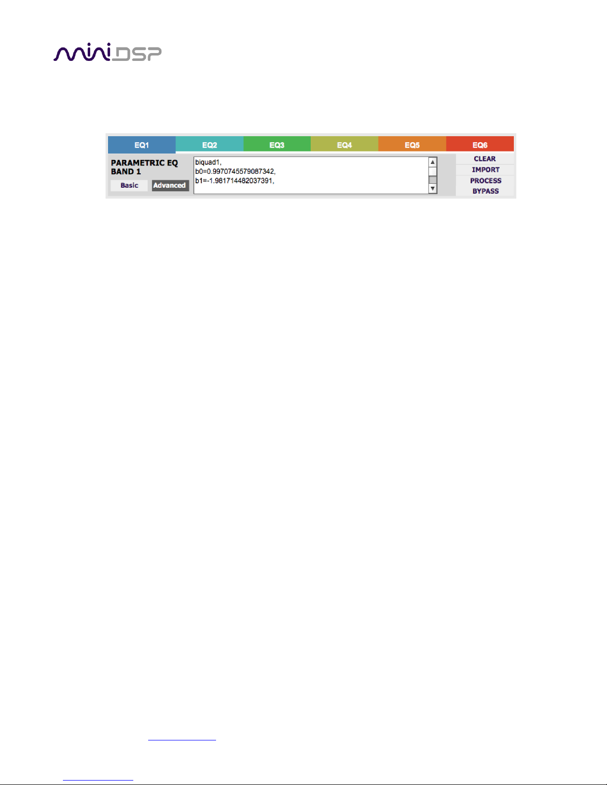
5.7.2 Using custom biquad programming
Each crossover block and PEQ filter has a selector that switches it to advanced mode:
In advanced mode, the biquad coefficients can be pasted directly into the user interface. These coefficients must
be calculated using a design program – see Biquad design software below for suggestions.
miniDSP Ltd, Hong Kong / www.minidsp.com / Features and specifications subject to change without prior notice 35
Parametric EQ advanced mode
In the PEQ blocks, advanced mode allows each individual filter to be specified by its biquad
coefficients. After pasting in the coefficients, click on the Process button for them to take effect.
Parametric EQ file import (REW integration)
Multiple biquads in the PEQ block can be set at once by importing a coefficient file. (Click on the
IMPORT button.) This file can be generated by Room EQ Wizard (REW) or by other programs. The
design program must be set for a 192 kHz sample rate for the C-DSP 8x12 plugin. The number of filters
is limited to a maximum of six.
This example illustrates the correct file format:
biquad1,
b0=0.998191200483864,
b1=-1.9950521500467384,
b2=0.996920046761057,
a1=1.9950521500467384,
a2=-0.9951112472449212,
biquad2,
b0=0.999640139948623,
b1=-1.9981670485581222,
b2=0.9985489719847982,
a1=1.9981670485581222,
a2=-0.9981891119334211,
biquad3,
...
biquad4,
...
biquad5,
b0=1.0010192374642126,
b1=-1.9950555192569264,
b2=0.9940580112181501,
a1=1.995060938714333,
a2=-0.9950718292249559
Note that the last line must not have a comma at the end. If the file has less than ten biquads, then
only that number of biquads will be imported. For example, if importing a file with six biquads, the first
six filters will be set, and the last four will not be changed. (Be careful: if the last line ends with a
comma, that counts as an extra biquad.)
If the file contains more than ten biquads, then an error will be reported and no filters will be changed.
Crossover advanced mode
The Xover (crossover) blocks have eight biquads on each output channel. In Advanced mode, all eight
biquads need to be specified. After pasting in the coefficients, click on the Process button for them to
take effect.

miniDSP Ltd, Hong Kong / www.minidsp.com / Features and specifications subject to change without prior notice 36
5.7.3 Biquad design software
Following are programs that can be used to design your biquad coefficients.
5.7.3.1 Biquad calculation spreadsheet
The community-developed biquad calculation spreadsheet allows many filter types to be calculated, including
notch filters, Linkwitz transforms, and filters with arbitrary Q-factor. Access this spreadsheet here (requires
Microsoft Excel):
• http://www.minidsp.com/images/fbfiles/files/All_digital_coefs_v1-20101026.zip
Be sure to set the sample rate to 192 kHz on any worksheet that you use.
5.7.3.2 Room EQ Wizard (REW)
Room EQ Wizard (REW) is a free acoustic measurement and analysis tool, available for Windows, Mac and Linux
platforms. It includes the ability to automatically generate a bank of parametric EQ biquads based on a
measurement. These coefficients can be saved to a file from REW and loaded directly into a PEQ bank in a
miniDSP plugin. Room EQ Wizard can be downloaded here:
• http://www.roomeqwizard.com/#downloads
For guidance on using this feature, please refer to the app note Auto EQ with REW.
Note: as of writing, REW does not have a dedicated setting for the C-DSP 8x12. To generate filters in the correct
format:
• Select the “Generic” filter type.
• Open the EQ filters screen and uncheck ten of the provided 20 filters.
• After clicking “Save filter coefficients to file,” select 192000 as the sample rate from the dropdown
menu. Save the file with a name ending in “.txt”.
• After saving, open the file and delete the unused filters (all coefficients are set to 0.0 except b0, which is
set to 1.0). Save the edited file.
• Use the plugin user interface to import the edited file into the desired PEQ filter bank. You should see
the filter graph change to be the same as the “Filters” graph in REW (turn off “Show each filter” in REW
to see the combined response).

miniDSP Ltd, Hong Kong / www.minidsp.com / Features and specifications subject to change without prior notice 37
5.8 WORKING WITH CONFIGURATIONS
The data that controls the audio processing C-DSP 8x12 is called a configuration. Four configuration presets are
stored in internal memory. Presets can be selected with the wired remote panel or with an infrared remote.
5.8.1 Online and offline mode
Initially, the plugin is in offline mode. When the Connect&Synchronize button is used, the plugin downloads
configuration data into the processor and goes into online mode. Changes made in the plugin user interface
therefore fall into two categories:
The plugin is in online mode
The plugin user interface is “live” – that is, any changes made to the audio processing parameters in
the user interface are immediately downloaded to the processor. The effect of these changes will thus
be audible as the changes are made.
The plugin is in offline mode
Changes made to audio processing parameters in the plugin user interface will be made on your
computer only. The next time the plugin is synchronized to the processor, the parameters will be
downloaded to the processor (provided the Synchronize Config button is selected).
The configuration contained in the miniDSP hardware unit cannot be uploaded back to the
computer. Therefore, you must save your configuration to a file if you wish to recover from any
changes you make while in offline mode.
5.8.2 Selecting a configuration
The active configuration is selected by one of the four buttons in the Configuration Selection area. By default,
configuration 1 is selected:
To switch to a different configuration, click on a different button. There are two cases:
The plugin is in online mode
Audio processing will switch to the parameters contained in the selected configuration. If, however,
parameters of the newly selected configuration have been changed since the last time that
configuration was synchronized to the processor, then a dialog will appear asking you if you want to
synchronize the configuration.
The plugin is in offline mode
The user interface will update to show the parameters of the newly selected configuration. If this
configuration is changed in the user interface, it will be downloaded to the processor the next time it is
synchronized.

miniDSP Ltd, Hong Kong / www.minidsp.com / Features and specifications subject to change without prior notice 38
5.8.3 Saving and loading configurations
Configurations can be saved to and loaded from files. Each configuration is stored in a separate file. It is very
strongly recommended that each configuration programmed into the processor be saved to a file, to ensure that
the configuration is not lost if the processor is inadvertently reset to defaults.
To save the currently selected configuration to a file, drop down the File menu, then select Save and then Save
current configuration to computer. In the file box, select a location and name of the file, and save it.
To load a configuration from a saved file, first select the configuration preset that you wish to load into
(“Config 1”, “Config 2” etc) . Drop down the File menu and select Load configuration to current slot.
If the plugin is in online mode, the new configuration data will be downloaded to the processor immediately. If
the plugin is in offline mode, the configuration will be loaded into the user interface only, and will be
downloaded to the processor the next time it is synchronized.
To copy a configuration from one preset to another, save the configuration to a file, then select
a different configuration preset and load the file.
5.8.4 Loading configurations from microSD card
The C-DSP 8x12 can load a set of configurations from a microSD card. This can be used to load new configuration
sets without requiring a computer connection.
1. Connect a microSD card to the computer. If the computer has an SD card slot, you can use a microSD
card adapter. Or, use an external card reader connected via USB. If the card hasn't previously been
formatted, format in FAT format.
2. Start the plugin. Don't connect or synchronize to the C-DSP 8x12. From the File menu, select Save and
then Save all configuration to SD card.

miniDSP Ltd, Hong Kong / www.minidsp.com / Features and specifications subject to change without prior notice 39
3. From the file save dialog box that opens, type in a file name, navigate to the SD card and click on Save.
This saves all four configurations to a special file on the SD card.
4. Eject the (micro) SD card from the computer.
5. Power off the C-DSP 8x12 if it is on. Insert the microSD card into the slot on the C-DSP 8x12 rear panel.
(It pushes in and latches.) Power on the C-DSP 8x12.
6. The C-DSP will load all four configurations. Each button on the wired remote will light as that
configuration is loaded.
7. Eject the microSD card. (Push it in gently to unlatch it, then pull it out.) The C-DSP 8x12 is ready for use
with a new configuration set.
5.8.5 Restoring to defaults
Configurations can be reset to the factory defaults from the Restore menu. There are two options:
Factory Default
Reset all four configuration presets to the factory default settings.
Current Configuration Only
Reset only the currently selected configuration preset to the factory default settings.
If the plugin is in online mode, the configuration data on the processor (all or just one configuration, as selected)
will also be reset to factory defaults. Otherwise, the reset will take place in the user interface only, and the new
configuration data will be downloaded to the processor next time it is synchronized.
5.9 KEYBOARD SHORTCUTS
The C-DSP 8x12 plugin supports the use of the keyboard for many operations.
Tab
The Tab key moves the focus from the current user interface element to the next. A blue-grey
surrounding box usually indicates the user interface element with the focus. Shift-Tab moves the focus
in the opposite direction.
Up/down arrows
The up/down arrow keys (and in some cases, the left/right arrow keys) adjust the value of many
parameters, if they have the focus:
• Output channel gain
• Crossover frequency and filter type
• PEQ filter frequency, gain, and Q
Space
The Space bar toggles buttons that have two states, such as Bypass, Invert, and Mute, if they have the
focus.
miniDSP Ltd, Hong Kong / www.minidsp.com / Features and specifications subject to change without prior notice 40
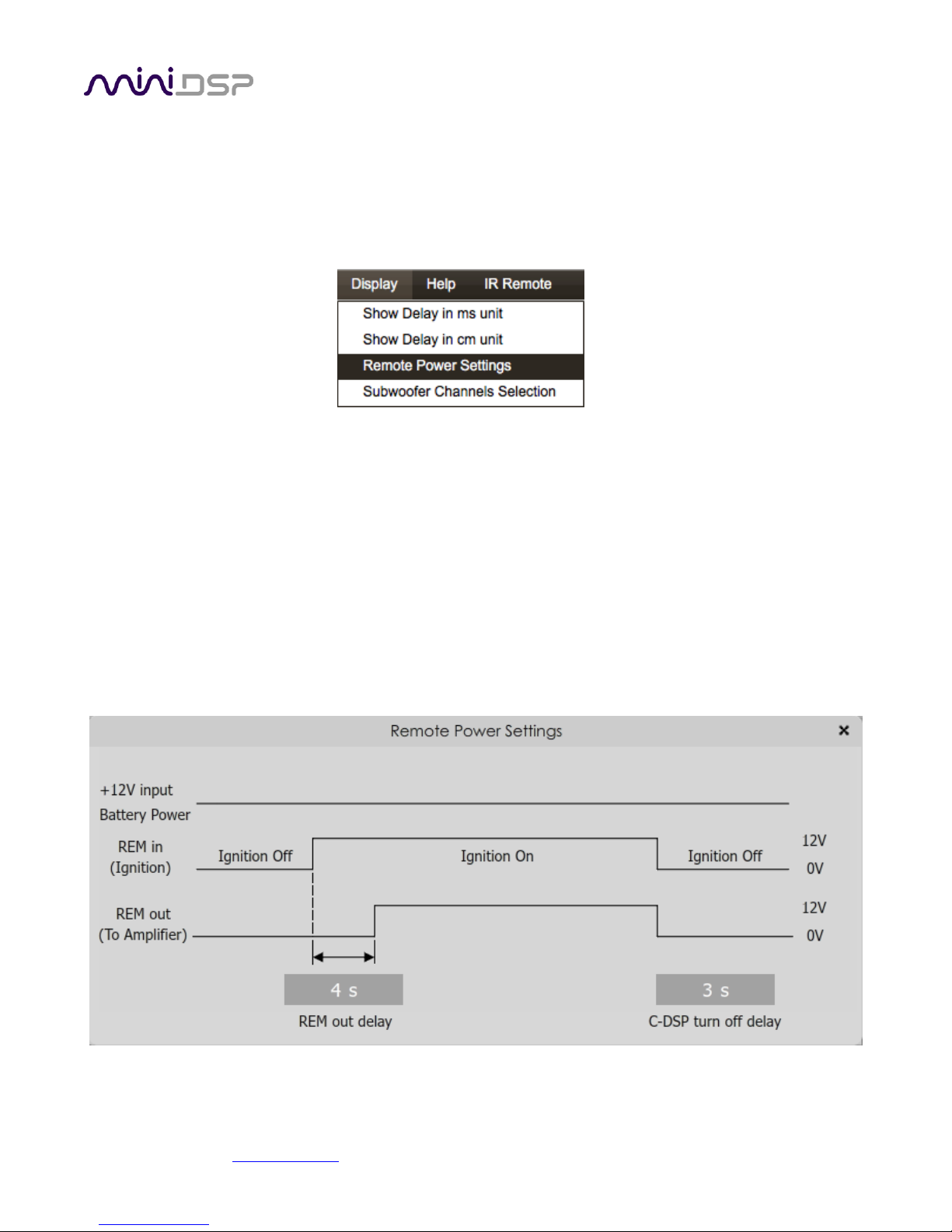
5.10 REMOTE TRIGGER TIMING
When the REMOTE MODE switch (see page 16) is set to position 2, the REMOTE OUT terminal can be used to
enable and disable power amplification.
The relevant delays can be configured from within the plugin. To do so, drop down the Display menu and select
Remote Power Settings.
On the screen, enter the desired value for each time delay parameter and press the Enter key. When finished,
click the close “X” icon at the top right, and the settings will be downloaded to the C-DSP 8x12.
(Note that the default settings are suitable 90% of installations. So there’s no need to change from the defaults
if it’s working fine for you.)
REM out delay
This value controls the delay from REMOTE IN going high to REMOTE OUT going high.
C-DSP turn off delay
This value controls the delay from REMOTE IN going low until the C-DSP 8x12 turns off.

miniDSP Ltd, Hong Kong / www.minidsp.com / Features and specifications subject to change without prior notice 41
6 USING THE C-DSP 8X12
Once configuration is complete, the computer is not required and
can be disconnected. The wired remote and/or an infrared remote
can be used to control:
• Master volume
• Master mute
• Preset selection
• Volume mode selection
6.1 STATUS INDICATORS
The currently selected preset is indicated by a blue LED in one of the selection buttons.
6.2 CONTROLS
To change the volume
Rotate the control knob clockwise to increase the volume, and counter-clockwise to decrease it. The
LED bar graph on the left indicates the master volume level setting.
To mute and unmute
Press on the control knob.
To change the preset
Press one of the four buttons. The LED of the selected preset will flash several times. When it stays lit,
the selected preset in now in operation. (Note: The preset cannot be changed with the wired remote
while there is a USB connection to the computer. Use the plugin instead.)
To change the volume control mode
Press buttons 1 and 2. LEDs 1 and 2 will light either solid or blinking, depending on the current mode.
Press button 4 to change the mode:
• LEDs 1 and 2 are solid (not blinking): Master Volume mode
• LEDs 1 and 2 are blinking: Subwoofer Volume mode
Press buttons 1 and 2 to return to normal operation.
To quickly adjust subwoofer volume while in Master Volume mode:
1. Press buttons 1 and 2, then button 4 to switch to Subwoofer Volume mode.
2. Adjust the rotary control until the subwoofer level sounds right.
3. Press button 4 to switch back to Master Volume mode.
4. Press buttons 1 and 2 to return to normal operation (for preset selection).

miniDSP Ltd, Hong Kong / www.minidsp.com / Features and specifications subject to change without prior notice 42
6.3 INFRARED REMOTE CONTROL
By default, the C-DSP 8x12 is programmed to accept control codes from the miniDSP infrared remote. It can also
learn codes from any other remote that supports one of the following remote control codes:
• NEC
• Sony
• Philips RC6
The infrared receiver is located in the wired remote module.
To initiate the learning process, drop down the IR Remote menu and select IR learning. Click on the Learn
button for an operation, and then press the desired button on the remote control. If the code is accepted, the
status will change to show a tick.
This screenshot shows the IR learning screen:
To "unlearn" a command, press the Learn button and wait for the plugin to time out.
The C-DSP 8x12 can also respond to the silver Apple Remote. (It will
not work with the newer Siri Remote.) To do so, “unlearn” all remote
commands by pressing the Learn button for each and waiting for the
plugin to time out. When done, all checkmarks will be removed and
the C-DSP will respond to the Apple Remote as shown in the diagram
at right.
(The commands Config Inc and Config Dec change the selected
configuration preset up or down. For example, if the currently selected
preset is 1, pressing Config Inc changes it to 2. Note that switching
between presets takes several seconds.)

miniDSP Ltd, Hong Kong / www.minidsp.com / Features and specifications subject to change without prior notice 43
7 ADDITIONAL INFORMATION
7.1 SPECIFICATIONS
Computer connectivity
Driverless USB 2.0 control interface for Windows and Mac OS X
Analog audio inputs
• 6 x high-level differential on terminal Block, max 8/12 VRMS (switch-selectable)
• 6 x low-level differential on RCA connectors, max 2/4 VRMS (switch-selectable)
Input impedance
Low-level inputs: 10 kΩ (4V setting) or 5 kΩ (2V setting)
High-level inputs: 68 Ω
Digital audio Input
• S/PDIF on RCA connector / Isolated with digital audio transformer
• TOSLINK optical
A high quality onboard Asynchronous Sample Rate Converter ensures compatibility
with most sample rates, from 44.1 up to 192 kHz.
Analog audio outputs
12 x unbalanced on RCA connectors, 6.0V RMS full scale output
Output impedance
560 Ω
Audio resolution
24-bit input and output, 192 kHz internal sample rate
Audio processing
400 MHz 32-bit Floating Point SHARC Digital Signal Processor, ADSP21489
Storage/presets
All settings controllable in real time from software user interface.
Up to 4 presets stored in local flash memory.
Wired external remote
External remote for control of active preset, master volume, subwoofer volume and
master mute. LED indication of master volume and active preset.
microSD Card
Allows setup without a laptop: a configuration can be built offline and loaded
automatically to the unit in the car via a microSD Card.
Infrared remote
“Learning remote” (NEC, Philips, Sony) controls master volume, mute, preset
selection.
Remote trigger
REMOTE IN: 4 V DC trigger level
REMOTE OUT: 12 V DC @ 100mA max current out
Power supply
Isolated DC-DC conversion, 10 to 14 V DC compliant for car audio environment
Dimensions (H x W x D)
47 x 246 x 120 mm

miniDSP Ltd, Hong Kong / www.minidsp.com / Features and specifications subject to change without prior notice 44
7.2 INPUT SENSITIVITY SETTING
The sensitivity of all inputs can be changed with a set of DIP switches internal to the unit. All inputs can have the
sensitivity set independently. To change input sensitivity settings, remove the top cover. Referring to Figure 3
below, move both switches for each input to the desired setting.
The switches are very small, so you will need a small device like the end of a paperclip to move them.
Don’t use force, just push the switch in the desired direction and it will “click” into the new position.
Table 1. Input sensitivity switch settings
Input type
Low level inputs
High level inputs
Switch setting
Off (default)
On
Off
On (default)
Full scale input voltage (RMS)
4V
2V
12V
8V
Input impedance
10 kΩ
5 kΩ
68 Ω
68 Ω
Figure 3. Input sensitivity switch locations
miniDSP Ltd, Hong Kong / www.minidsp.com / Features and specifications subject to change without prior notice 45
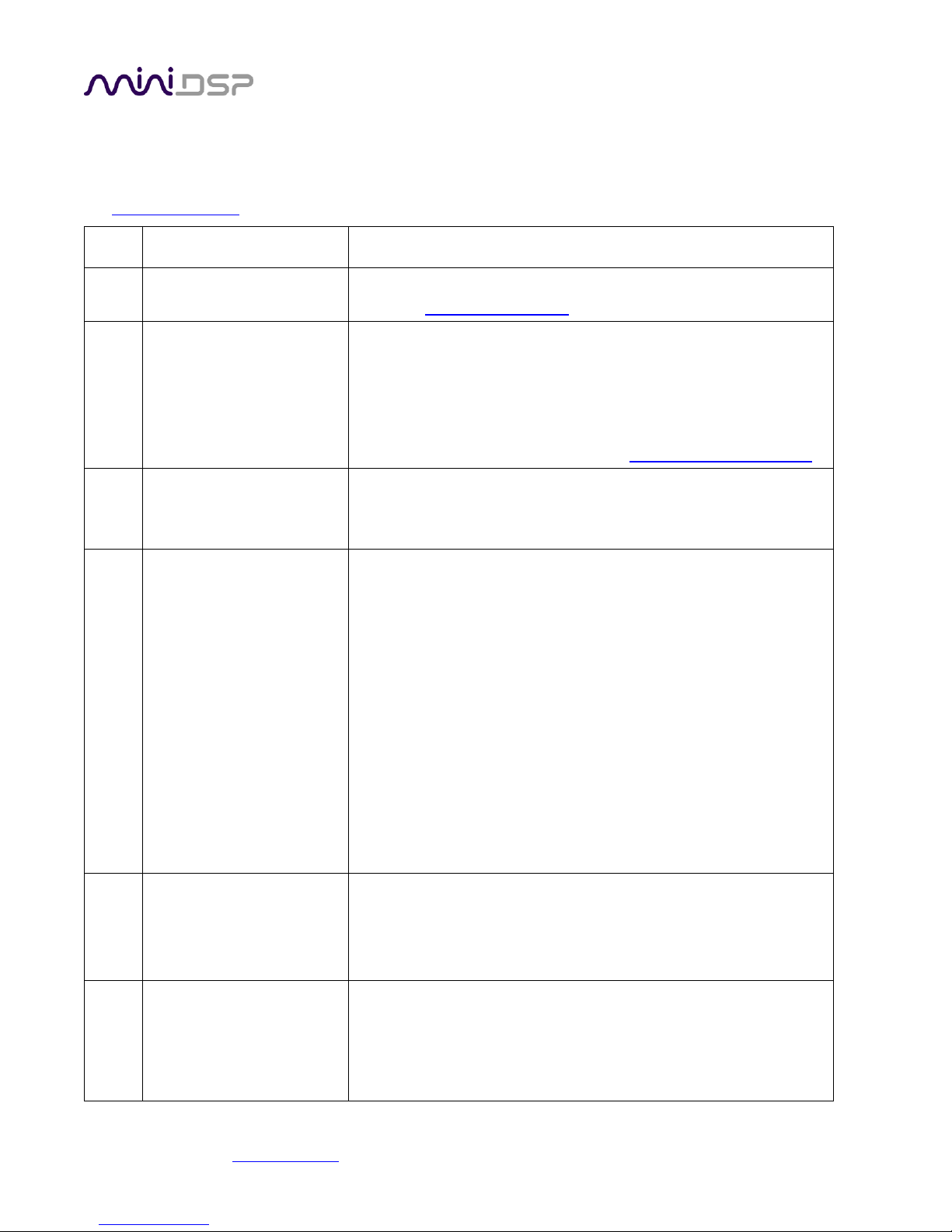
7.3 TROUBLESHOOTING
The following table lists the most common causes of issues. If following this table does not provide a solution,
see Obtaining Support below.
Item#
Symptoms
Troubleshooting recommendation
1
Cannot install software
a. (Windows) Confirm that required frameworks are installed
(see Software Installation).
2
Software running in
background but not
showing
a. The Adobe Air environment may need a network connection
the first time you run a plugin. Close the plugin program,
ensure that your computer has a network connection, and
restart the plugin.
b. The Adobe Air environment may require a version update.
Download the latest version from http://get.adobe.com/air/.
3
Cannot connect to the
board by USB
a. Reset the processor by power-cycling the unit.
b. Make sure the processor is seen in the device manager as a
HID device.
4
No audio or low audio on
outputs
a. Check the cabling from the processor to your amplifiers.
b. Check that your amplifiers are turned on and that any volume
controls are turned up.
c. Check that the input meters and output meters are showing
adequate signal (if not, see item 5).
d. Check that master mute is not enabled.
e. Check that the mute buttons in the output control blocks are
not enabled.
f. Check that your crossover frequencies are correct e.g. that
you don’t have high pass and low pass frequencies incorrectly
set.
g. Check that the matrix mixer is sending the correct inputs to
the correct outputs.
5
No signal showing on input
meters
a. Check the cabling from your source/s.
b. Check that your source is playing audio and that it is not
muted or have volume control turned down.
c. Check that the plugin is synchronized with the hardware unit.
6
Audio sounds distorted
a. Check the input meters and ensure that you are not
overloading the inputs. If necessary, reduce the signal level
from the source or change the input sensitivity switches.
b. Check the output meter and ensure that you are not
overloading the outputs. If necessary, reduce the output gain
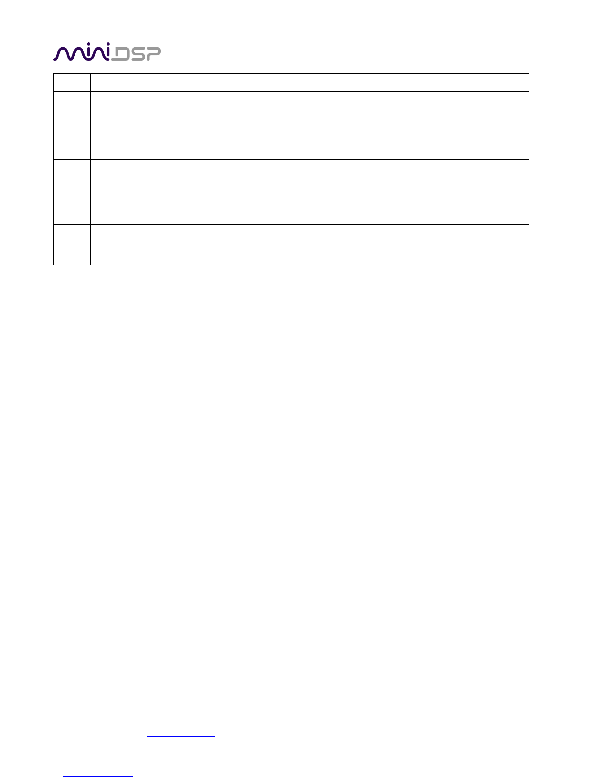
miniDSP Ltd, Hong Kong / www.minidsp.com / Features and specifications subject to change without prior notice 46
and/or the amount of boost in the EQ blocks.
6
Audio is coming through
the wrong outputs
a. Check the cabling from the processor to your amplifiers.
b. Check the cabling from your source/s.
c. Check that you have correctly set up the matrix mixer to send
the correct inputs to the correct outputs.
7
Other audio-related issues,
or issues not resolved.
a. Check that you have downloaded the latest version of the
plugin.
b. Check that your processor has the latest firmware installed
(About menu).
8
Cannot reload a
configuration
a. Confirm the file format of your file (.xml).
b. Confirm the version of the file.
7.4 OBTAINING SUPPORT
1. Work through the Troubleshooting checklists starting on the previous page.
2. Check the forums on miniDSP.com to see if your issue has already been raised and a solution provided.
3. Contact miniDSP via the support portal at minidsp.desk.com with:
a. The specific product you are having an issue with (in this case, C-DSP 8x12).
b. A clear explanation of the symptoms you are seeing.
c. A description of the troubleshooting steps performed and your results.
 Loading...