

Page 1

GPS Speaker Microphone with Frequency Domain Scrambler
GPS Speaker Microphone with Rolling Double Inversion Scrambler
GPS Speaker Microphone with Double Inversion Scrambler
GPS Speaker Microphone with Voice Inversion Scrambler
Manual Revision: 2013-05-01
Covers Firmware Revisions:
VS: 1.60 & Higher
Covers Hardware Revisions:
VS-SM1: B & Higher
VS-1200-SM1G
VS-115-SM1G
VS-1150-SM1G
VS-1050-SM1G
1
Page 2

HARDWARE SPECIFICATIONS
Operating Voltage 3.5-8.0 VDC
Operating Current: VS-1050-SM1G (No GPS Power Save Mode)
Power Save Mode (VOX Operation) 56 mA typical
Normal Operation - TX 56 mA typical
Normal Operation – RX 94 mA typical
Average w/VOX Power Save (80-10-10 cycle) 60 mAh*
Average w/VOX Power Save (90-5-5 cycle) 58 mAh*
Operating Current: VS-1050-SM1G (with GPS Power Save Mode)
Power Save Mode (VOX Operation) 18 mA typical
Normal Operation - TX 19 mA typical
Normal Operation – RX 94 mA typical
Average w/VOX Power Save (80-10-10 cycle) 26 mAh*
Average w/VOX Power Save (90-5-5 cycle) 22 mAh*
Operating Current – VS-1200, VS-115, VS-1150 (No GPS Power Save Mode)
Power Save Mode (VOX Operation) 59 mA typical
Clear or Inversion Operation - TX 60 mA typical
Clear or Inversion Operation – RX 102 mA typical
FFT Scrambling Operation - TX 100 mA typical
FFT Scrambling Operation – RX 148 mA typical
Average w/VOX Power Save (80-10-10 cycle) 39 mA*
Average w/VOX Power Save (90-5-5 cycle) 30 mA*
Operating Current – VS-1200, VS-115, VS-1150 (With GPS Power Save Mode)
Power Save Mode (VOX Operation) 21 mA typical
Clear or Inversion Operation - TX 32 mA typical
Clear or Inversion Operation – RX 102 mA typical
FFT Scrambling Operation - TX 72 mA typical
FFT Scrambling Operation – RX 148 mA typical
Average w/VOX Power Save (80-10-10 cycle) 73 mA*
Average w/VOX Power Save (90-5-5 cycle) 67 mA*
Operating Temperature -30 - +60 C
Frequency Response 300-3000 Hz
Input Impedance >33
Input Level (RX) 0.05-2.5 VPP
Audio Output Impedance (Single Ended with R-12 uninstalled) 47 KΩ
* - The transmit and receive cycles are based on scrambled mode. When using clear mode, the consumption will decrease.
2
Page 3

SECURITY SPECIFICATIONS
VS-1200:
Total Code Combinations ~6.2 x 10^23
Actual Code Combinations ~4 Billion
Number of Selectable Keys 3
Levels of Security 5
Inversion 2100-4100 Hz (0-15 Hz resolution)
Level 0 8 bins
Level 1 16 bins
Level 2 32 bins
Level 3 64 bins
VS-115:
Total Number of Codes 1020
Number of Codes 255
Number of Groups 4
Number of Selectable Codes 4
VS-1150:
Total Number of Codes 32
Number of Selectable Codes 4
VS-1050:
Number of Selectable Codes 4
Inversion Frequency Range 2100-4100 Hz (0-15 Hz resolution)
ANI SPECIFICATIONS
Midian’s FMP Unit ID Range 00000-FFFFF
Midian’s FMP Group ID Range 000-FFF
Midian’s FMP ANI Timing with Coordinates 413 msec
Midian’s FMP ANI Timing without Coordinates 200 msec
DTMF ANI Length Up to 6-digits
DTMF ANI Timing 60/40 msec (Programmable)
5-Tone ANI Length Up to 6-digits
5-Tone ANI Timing Programmable
G-Star ANI Range 0001-9999
G-Star ANI Timing 320 msec
Motorola’s MDC-1200 ANI Range 0000-FFFF
Motorola’s MDC-1200 ANI Timing ~180 msec
Kenwood’s FleetSync Unit ID Range 1000-4999
Kenwood’s FleetSyncUnit ID Timing ~100-150 msec
INSTALLATION OVERVIEW
1. Test the radio for functionality.
2. Program the unit per the Product Programming Section of this manual.
3. Install the unit into the radio per the Hardware Installation Section of this manual.
*** Midian is not responsible for any damage/loss resulting from the use of Midian’s products.
3
Page 4

GENERAL INFORMATION
Midian’s GPS speaker microphones encode a user’s GPS coordinates along with the user’s ANI and Emergency
ANI to display on Midian’s CAD-800 or CAD-800U base station controllers. The following is a list of benefits
provided by Midian’s GPS systems:
Allows dispatchers to know who he or she is talking to.
Identify system abusers.
Identify emergency conditions.
Assign calls fairly.
Track user location.
Midian’s SM1G series encodes ANI and Emergency ANI along with Midian’s GPS location reporting to Midian’s
CAD-800 or CAD-800U which uses a Google Earth interface to display the unit’s location on a map.
The SM1G series also offers Man-Down and Lone Worker features. If the unit does not detect movement (ManDown) or receive any user interaction (PTT or Lone Worker Reset button) for a programmable period of time the
unit can key the radio and send the Emergency ANI.
In addition to the above encoding features, Midian’s GPS speaker mics can decode commands from the CAD-800
such as Polling, Selective Calling, Radio Disable, Radio Enable, Spy (Remote Monitoring) and Emergency
Acknowledge. Polling allows the dispatcher to request a unit’s GPS location. Selective calling can be to call an
individual unit, a group of units or all units. If a unit becomes lost or stolen, it can be disabled, so it cannot
interfere with the system. If the unit is later recovered the unit can be re-enabled. The Spy function enables the
dispatcher to eavesdrop on a unit during an emergency or other condition. If multiple Emergency IDs are
transmitted, the dispatcher can stop subsequent Emergency ID transmissions using the Emergency Acknowledge
feature.
VS-1200:
The VS-1200 is a Digital Signal Processor (DSP) based Frequency Domain voice scrambler offering a high level
of voice privacy. The DSP converts the analog signal into quantitized digital data. It then converts the “Time
Domain” signal into the “Frequency Domain”. This results in an audio “frequency spectrum”, which is then
partitioned into bins that are encrypted by the non-linear key generator. The digitized data is converted back to
the analog realm using a digital to analog converter.
The above technique and the lack of synchronization result in excellent audio quality, high security and enable the
VS-1200 to be used in virtually any type of radio system. These systems include HF SSB, Conventional TwoWay, Trunking, Voting and Simulcast.
VS-115:
Midian’s VS-115 is a rolling double inversion scrambler that offers 1020 possible codes (4 groups with 255 codes
per group). Of these codes the scrambler may be programmed with up to 4 of these codes. The VS-110 series is
compatible with Icom’s UT-110.
VS-1150:
Midian’s VS-1150 is a double inversion scrambler (aka split-band scrambler) that offers 32 possible codes. Of
these 32 codes the scrambler may be programmed with up to 4 of these codes. The VS-1150 series is compatible
with Midian’s VPU-6, Icom’s UT-109 or Inysa’s XPTO.
VS-1050:
Midian’s VS-1050 is a voice inversion scrambler that provides up to 4 different inversion frequencies that are
button selectable. The programmable inversion frequency range is from 2100 Hz to 4096 Hz and provides
compatibility with Midian’s VPU series voice inversion scramblers, as well as other industry inversion scramblers.
4
Page 5

HARDWARE INSTALLATION
Be certain to follow standard anti-static procedures when handling any of Midian’s products.
For all diode protected inputs (i.e. PTT Input, Mode Input, COR Input) the voltage level to be required for a logic
low is less than 0.5 V and a logic high requires at least 2.1 V.
J1 – RJ-48 10-Pin Connector:
J1:1 – Program In: The KL-4 Option B or KL-4F-PC2 must be plugged in to access this pin for programming.
J1:2 – PL DIS: Hook switch for mobile radio applications.
J1:3 – MIC: Connect to the MIC+ connection on the radio’s external mic connector
J1:4 – Ground: Connect to a ground connection on the radio’s exte rnal mic connector.
J1:5 – COR/LTR: Future use.
J1:6– B+ (+3.5-8.0 VDC): This connection is only needed if not using the internal battery of the SM1. Connect to
B+ (3.5-8.0 VDC) connection on the radio’s external mic connector. If connecting to a mobile this must be
specified when ordering or you must install a 6.2 V Zener diode at D1 if the voltage is higher than 9.7 V. Connect
to a regulated voltage point in a vehicular radio if engine noise is present on the battery line. With D1 installed, the
voltage input could be as high as 15 VDC (nominal is 13.5 VDC). R-5 O Ohm resistor must be installed. Note: If
connecting this input DO NOT install the battery into the microphone and U1 must be removed.
J1:7 – PTT: Connect to a PTT connection on the radio’s external mic connector used to key the radio. Some
radios look for a resistance on the microphone input to trigger PTT, R-50 in the SM-1 is used for this purpose and
will need to be picked on an individual radio basis. For Vertex radios this should be a 2.7 K resistor.
J1:8 – SPK Ground (SPK-): If connecting to a radio with a double ended speaker, then connect this line to the
negative side of the speaker connection on the external mic connector. If connecting to a radio with a single
ended speaker, this line is not connected.
J1:9 – SPK Hi (SPK+): Connect this line to the positive side of the speaker connection on the external mic
connector.
J1:10 – Program Out: The KL-4 Option B or KL-4F-PC2 must be plugged in to access this pin for programming.
J2 – 3.5 mm Stereo Connector:
The 3.5 mm stereo connector on the SM1 is a dual purpose connector; charging and audio. The tip is 6V for
charging, ring is Speaker + and sleeve is ground. Use only Midian supplied wall power adaptors and audio
accessories for use with the SM1.
Charging: To charge the unit, plug the Midian supplied wall power adaptor into an outlet and then plug the 3.5
mm plug into the 3.5 connector on the unit. When the LED is glowing green the unit is charging. When the LED
goes out then it is done charging. When the unit is in need of a charge the unit will emit a descending series of
tones to indicate low battery. Only use Midian provided accessories for charging.
Audio: The 3.5 mm connector can be used as an audio accessory port (i.e. ear bud). The connections should be
ring as Speaker + and Sleeve as ground. Not using a Midian supplied audio accessory could result in damage to
the unit.
5
Page 6

PRODUCT PROGRAMMING
Midian’s SM-1 products are programmed via Midian’s KL-4F and KL-4F-PC2 or the KL-4 and KL-4 Option B, as
well as the MPS software. Please reference the KL-4 manual for setup instructions of the programming software
and hardware. From the product selection screen in the software, select the desired SM1G model from the list
and click OK.
Set the parameters of the software to fit the application. If any clarifications on a feature are required, move the
mouse cursor over the feature name until the question mark appears and right click, a definition of the feature will
be shown.
After entering the parameters, save the file by going to File - Save As. Enter the file name in the File Name block
and click Save. Saving the file will allow for quick and easy reprogramming of units.
If using the KL-4F, plug the KL-4F-PC2 cable from the KL-4F’s RJ-11 connector (P10) into the RJ-48 connector
on the SM1.
If using the KL-4, plug the KL-4 Option B cable from the KL-4 connector labeled “P4 VPU-12A” into the RJ-48
connector on the SM1.
Push the power button on the KL-4F or KL-4 and within 15 seconds select Program Unit or Read Unit in the
software. Upon power up the unit will be awake for 15 seconds before going into Power Save mode.
After programming or reading the unit, turn off the unit for 3 seconds and then turn back on.
6
Page 7
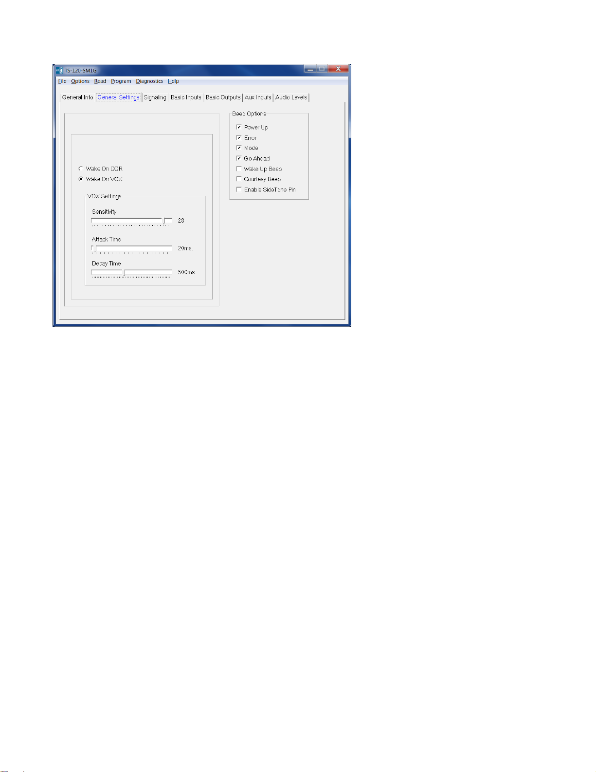
Wake on COR/Wake on VOX: Select the appropriate method that the unit should use to come out of power save.
Note: Most portables do not provide COR detection on the speaker mic port, so it will be necessary to use VOX
detection.
COR Hold-Up Time This is the amount of time after loss of COR/VOX that the unit considers COR/VOX dropped.
VOX Settings > Sensitivity: This is a threshold detection based on the energy level in the audio.
VOX Settings > Attack Time: This sets the minimum time before the unit will detect VOX.
VOX Settings > Decay Time: This sets the time before the unit will drop the VOX detection. Be certain to set this
long enough so that you do not have drop outs between words or on brief pauses.
Beep Options > Power Up: Enables a short beep sequence that takes place immediately after po wer-up.
Beep Options > Error: This beep may be triggered by any input event if programmed to do so. For example, if a
long press on the Mode Input is not assigned to a function, it may be configured to generate the error beep. If
there is a failure of the GPS module, then about 20 seconds after power up the error beep will be heard.
Beep Options > Mode: This is used to indicate to the user when the mode has been enabled/disabled (i.e. Lone
Worker enabled).
Beep Options > Go Ahead: This is a local beep out the speaker to indicate to the user that ANI has been sent
and it is okay to talk.
Beep Options > Wake Up Beep: Enables a short beep to be sent over the air after PTT is pressed. Enabling this
beep is recommended when the 'Wake on VOX' feature is used.
Beep Options > Courtesy Beep: If selected, once the PTT button is released, the unit will generate a courtesy
tone to let others know it is done transmitting.
Beep Options > Enable Side Tone Pin: Future Use.
7
Page 8
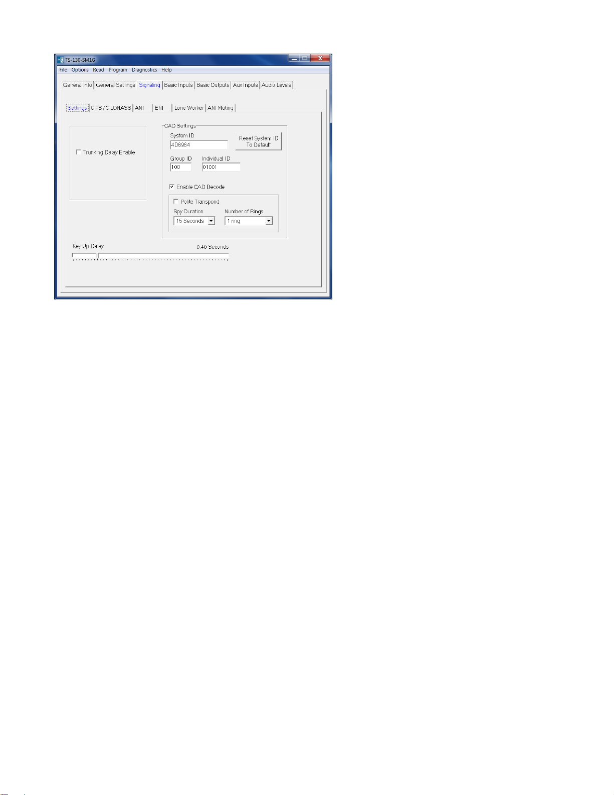
Trunking Delay Enable: Check this box if using a trunking system. This will cause the unit to hold off transmitting
the ANI until it has received a channel acquisition acknowledgement from the radio. This field is not used with
portable radios.
Key-Up Delay: This sets the amount of time the unit waits after keying the radio before it transmits the ANI.
CAD Settings:
System ID: Set this field to the same value as the System ID programmed into the CAD-800 or CAD-800U. Only
a CAD-800 with the same System ID can decode the GPS location information from the GPS speaker mic. This
field is a six character field that supports 000000-FFFFFF (0-9 & A-F) for a total of 16,777,216 possible System
IDs.
Restore System ID To Default: Pressing this button will return the System ID to Midian’s default System ID of
4D6964.
Group ID: This sets the group number that the unit is a part of. The Group ID is a 3 character field that supports
000-FFF (0-9 & A-F) for a total of 4096 groups.
Individual ID: This sets the unit’s identification number. The Individual ID is a 5 character field that supports
00000-FFFFF (0-9 & A-F) for a total of 1,048,576 unit IDs per group. Between all groups and unit IDs the total
number of supported IDs by the system is 4,294,967,296.
Enable CAD Decode: Checking this box enables Midian’s FMP signaling features such as Polling, Radio
Disable, Radio Enable, Selective Calling, Remote Monitoring and Emergency Acknowledge.
Polite Transpond: If the unit is required to transpond in response to a command from the CAD-800, it will do so
immediately after receiving the command. Checking this box will cause the unit to check for a busy channel
indication (using VOX or COR) before transponding. If the channel is busy, the transpond will be postponed until
the channel is no longer busy.
Spy Duration: When a Spy command (remote monitoring) is received from the CAD-800, this sets the amount of
time that the speaker mic will key-up the radio and transmit audio from the microphone.
Number of Rings: This sets the number of times the speaker microphone will ring when it receives a selective
call before timing out.
8
Page 9
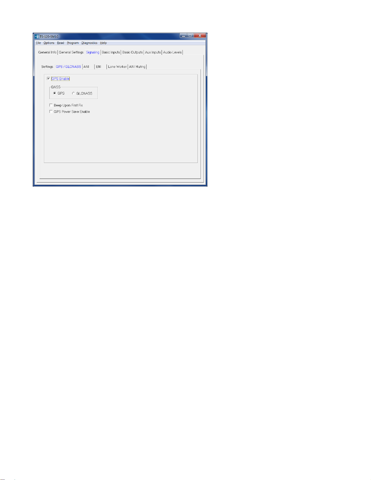
GPS Enable: Check this button to enable the GPS or GLONASS features of the product.
GNSS: Select which Global Navigation Satellite System (GNSS) is being used GPS or GLONASS. GPS is the
United States’ form of GNSS. GLONASS is Russia’s form of GNSS. GLONASS is currently in development.
Please contact Midian for the availability of GLONASS in the GPS speaker microphone.
Beep Upon First Fix: If checked, the GPS speaker microphone will give a double beep once the GPS speaker
microphone has acquired a location fix. The time to acquire a fix is dependent upon various conditions such as
terrain, buildings, weather, etc. Under ideal conditions this time could be as fast as 30 seconds. A first fix
acquisition time of 2-3 minutes would not be abnormal under other conditions.
GPS Power Save Enable: Checking this box will help extend battery life by placing the GPS receiver in a low
power or “sleep” state for 30 seconds in between position fixes. Upon waking, the GPS receiver is left on at full
power until two valid position fixes are determined and then once again is placed in sleep mode. Under good
signal conditions it takes about 20 seconds for the GPS receiver to acquire new fixes after waking. Therefore one
can expect a new fix to be determined about once per minute, though this cannot be guaranteed.
9
Page 10

Signaling Position Settings: Leading and trailing signaling types (ANI, FMP and FMP w/GPS) can be selected
here. For example MDC-1200 can be sent on the leading edge and Midian’s FMP with GPS can be sent on the
trailing edge.
ANI: The ANI specified in this selection is not the typical FMP ID used by Midian’s GPS speaker mics. Instead
this refers to ANI formats such as MDC-1200, FleetSync, DTMF, 5-Tone or GE-Star. One of these formats can be
selected to send a pre-ANI or post-ANI.
FMP: This refers to Midian’s signaling protocol used in the GPS speaker microphone minus the GPS location
information.
FMP w/GPS: This refers to Midian’s signaling protocol used in the GPS speaker microphone including the GPS
location information.
Protocol Format: Select the desired signaling format in which the ANI and ENI will be transmitted.
Tone Duration: This field only applies to DTMF and 5-Tone formats and sets the length of each tone.
Tone Gap Duration: This field only applies to DTMF and sets the length of the gap between tones.
Fleet ID: This field only applies to FleetSync and sets the Fleet ID of the unit.
Unit ID: This sets the non-FMP ANI of the unit.
Message: This field only applies to G-Star.
Status: This field only applies to G-Star.
Repeat Delay: This sets the time after sending an ANI that the unit will wait before sending another ANI.
10
Page 11
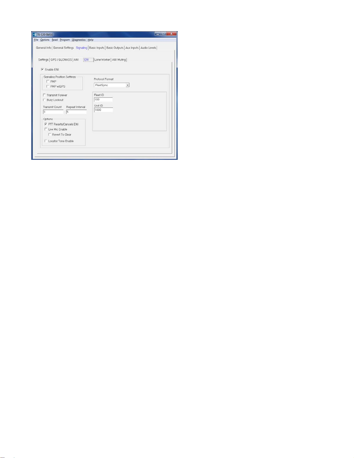
FMP: This refers to Midian’s signaling protocol used in the GPS speaker microphone minus the GPS location
information.
FMP w/GPS: This refers to Midian’s signaling protocol used in the GPS speaker microphone including the GPS
location information.
Protocol Format: This displays the format selected on the ANI tab.
Fleet ID: This field only applies to FleetSync and sets the Fleet ID for the ENI.
Unit ID: This sets the Emergency ANI of the unit.
Message: This field only applies to G-Star.
Status: This field only applies to G-Star.
Transmit Forever: If selected the ENI will transmit continuously at the repeat interval until canceled.
Busy Lockout: When it is time to transmit the ENI, if this box is not checked the transmission will take place
regardless of whether or not the channel is busy. If this box is checked and the channel is busy (as indicated by
COR or VOX), the ENI will not be transmitted. Instead the unit will wait 2.3 seconds and then check again to see if
the channel is busy. If the channel is not busy at that time, the ENI will be transmitted. If, not the process will
repeat indefinitely.
Transmit Count: This sets the number of times the ENI will be sent.
Repeat Interval: This sets the time between ENI transmissions.
PTT Resets/Cancels ENI: If selected, pressing the PTT button will either reset the Lone Worker’s Transmit Delay
time or cancel the transmission of the ENI.
Live Mic Enable: If selected the unit will enable the mic of the radio to transmit mic audio to the dispatcher.
Revert to Clear: This will switch the TX mode to Clear when using Live Mic.
Locator Tone Enable: If selected the unit will emit tones out the speaker after all Emergency ANI’s have been
sent. This feature is not available if Transmit Forever is checked.
11
Page 12
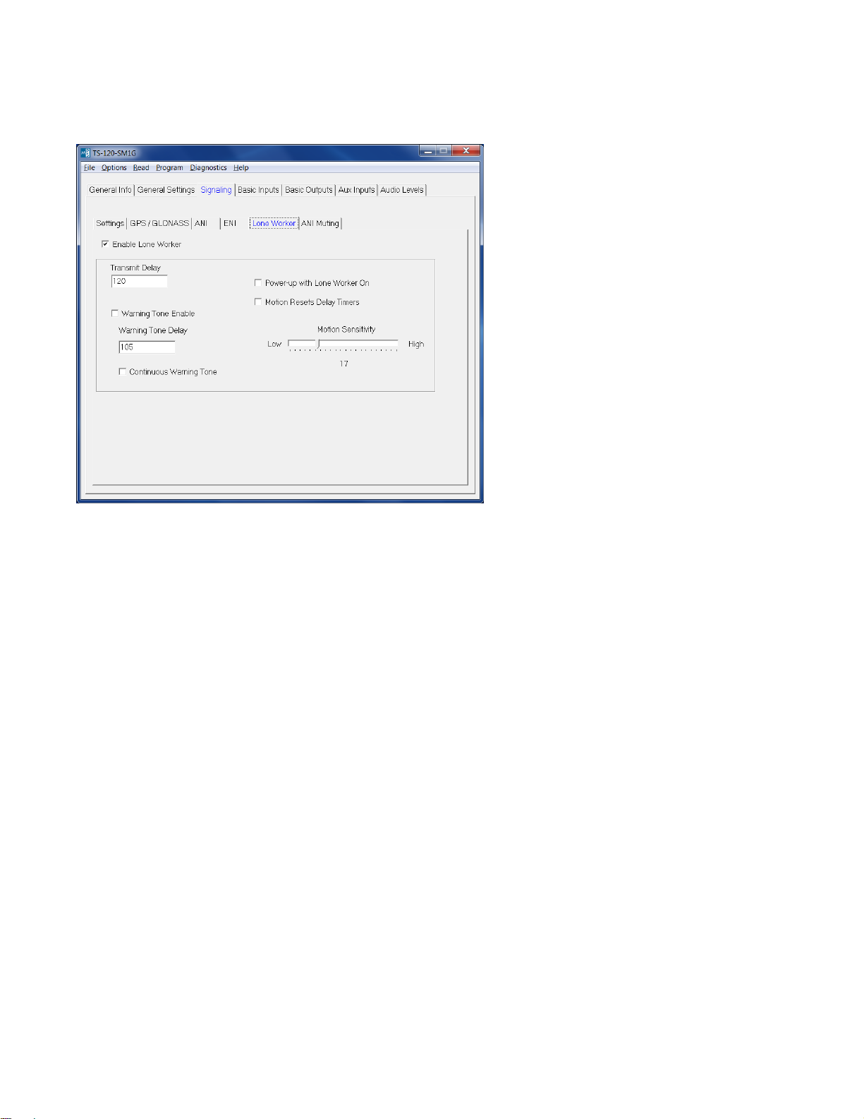
Transmit Delay: In Lone Worker mode, if the user does not interact with the radio before this amount of time
passes, the ENI sequence will be transmitted. This time is in seconds.
Warning Tone Enable: This will generate a tone sequence to alert the user the ENI is about to be transmitted.
Warning Tone Delay: In Lone Worker mode, if the user does not interact with the radio before this amount of
time passes, the emergency warning tone will be sounded. This amount of time must be less than that of the
Transmit Delay for the warning tone to be sounded. Also, the Warning Tone Enable box must be checked for the
tone to be sounded. For example, based on the screen shown above after 105 seconds of no activity the unit will
generate warning tones. The user then has 15 seconds (120 minus 105) to interact with the radio to keep the
Transmit Delay time of 120 seconds from expiring and the ENI being transmitted.
Continuous Warning Enable: This will generate a constant tone to alert the user the ENI is about to be
transmitted.
Power-up with Lone Worker on: If checked the unit will be in Lone Worker mode when the radio is turned on.
This eliminates the need for the user to use the mode input to turn the Lone Worker mode on.
Motion Resets Delay Timers: The unit can use the accelerometer to detect motion based on the Motion
Sensitivity setting to determine if the user is in distress in addition to requiring interaction with the radio.
Motion Sensitivity: This sets a level of motion required to reset the Transmit Delay timer. Some work
environments may have an inherent level of motion that would be detected by higher settings of the
accelerometer, so a lower level of sensitivity might be needed. Midian recommends experimenting to determine
the best sensitivity setting for the work environment.
12
Page 13

Mute GPS or MDC-1200 ANI Packet: If checked, the unit will detect incoming GPS or MDC-1200 ANI packets
and will mute the speaker for the Mute Duration time. A small chirp will still be heard out the speaker.
Mute Duration: This sets the amount of time after the unit detects the incoming packet that it will keep the
speaker muted. Midian’s GPS data packet without location is 200 msec and with location is 410 msec. Motorola’s
MDC-1200 data packets are approximately 180 msec in length.
Packet Detector Sensitivity: This controls the sensitivity of the preamble tone detector which triggers the muting
of the data packets. If it is too sensitive (higher number), voice may cause the detector to trigger resulting in voice
being muted when it should not. If it is not sensitive enough (lower number), the detector may not trigger when it
is supposed to. Adjust the sensitivity as needed to achieve the desired results. For the GPS speaker microphones
with scrambling, there is a separate sensitivity adjustment for when the unit is in scramble mode.
13
Page 14

These fields set how the switch is used (short press, long press or double press) and for which function (Scramble
On/Off, Lone Worker enable, Lone Worker Reset, Emergency On/Cancel, etc.).
Note: Most portable two-way radios do not give a COR indication to the speaker microphone connector, so VOX
detection should be used.
COR > Active Polarity: This sets whether the unit looks for an active low or active high to come out of power
save.
COR > Debounce: If checked the unit will require a continuous active state for 30 msec before accepting the
COR.
14
Page 15

PTT > Active Polarity: This sets the polarity necessary for the unit’s PTT output to key the radio.
15
Page 16

This page only applies to the VS-1200 product.
Number of Keys: The VS-1200 can have up to 3 codes programmed into the unit. The codes can be
programmed for either Frequency Domain or Voice inversion scra mbling.
Power Up In Scramble Mode: If selected the unit will start up in secure mode when the power is turned on. If it is
desired to have the unit always in secure mode, then check this box and do not assign a button for mode select.
Binary Select Enable: Not used in the VS-1200-SM1G.
Binary Select Polarity: Not used in the VS-1200-SM1G.
Equalization: Selecting Bass will yield louder recovered audio with good low frequency response. Selecting Treble
increases the high frequency response resulting in recovered audio that sounds more crisp but is not as loud. This
setting is a matter of preference. Note: All scramblers in the system must have this field set the same.
High Security: When High Security is selected the VS-1200 is using the Frequency Domain type of scrambling.
Security Level: The VS-1200 has four levels of Frequency Domain scrambling; levels 0, 1, 2 and 3. Level 0
offers 8 shuffling bins, Level 1 offers 16 shuffling bins, Level 2 offers shuffling 32 bins and Level 3 offers 64
shuffling bins. As the level of security is increased the audio quality will decrease.
Inversion: The VS-1200’s codes can also be programmed for basic voice inversion scrambling. If selected a
slider bar will appear. Merely scroll with the left/right arrows or grab the slider with the mouse and move to the
desired inversion frequency between 2100 to 4096 Hz.
16
Page 17

This page only applies to the VS-115-SM1G.
Number of Codes: The VS-115-SM1G supports up to 4 codes. The codes can be programmed for either Rolling
Double Inversion or Fixed Double Inversion scrambling.
Power Up In Scramble Mode: If selected the unit will start up in secure mode when the power is turned on. If it is
desired to have the unit always in secure mode, then check this box and do not assign a button for mode select.
TX Pre/De-emphasis Enable: This setting controls the use of audio emphasis by the scrambler while
transmitting. If checked, the scrambler will perform pre-emphasis before scrambling and de-emphasis after
scrambling. If the radio performs pre-emphasis of TX audio after the scrambler insertion point, this box should be
checked. If this information is not known, choose the option that yields the best recovered audio quality. See the
diagram on the next page.
RX Pre/De-emphasis Enable: This setting controls the use of audio emphasis by the scrambler while
receiving. If checked, the scrambler will perform pre-emphasis before de-scrambling and de-emphasis after descrambling. If the radio performs de-emphasis of RX audio before the scrambler insertion point, this box should
be checked. If this information is not known, choose the option that yields the best recovered audio quality. See
the diagram on the next page.
Continuous Synchronous Capture: This setting determines what will happen if a rolling code synchronization
tone is received after the receiving scrambler has already synchronized and is de-scrambling. If this checkbox is
cleared, a synchronization tone received before it is expected will be ignored. This may help prevent the
receiving scrambler from incorrectly synchronizing on some tones in speech. However, the receiving scrambler
may fail to synchronize properly with another scrambled transmission started immediately following the end of the
previous transmission, preventing the first few seconds of the second transmission from being properly
descrambled. If this happens frequently, this checkbox should be checked to enable Continuous Synchronous
Capture mode, which instructs the receiving scrambler to re-synchronize any time a new synchronization tone is
received.
17
Page 18

Tone Start Timing: The transmitting scrambler will wait this amount of time before transmitting the first rolling
code synchronization tone. Repeater systems and systems using CTCSS or DCS require time to 'open up' and
pass audio. This delay allows that time to transpire before the first synchronization tone is transmitted.
Binary Select Enable: This feature is not available in the VS-115-SM1G.
Binary Select Polarity: This feature is not available in the VS-115-SM1G.
18
Page 19

This page only applies to the VS-115-SM1G.
Code 1-4:
Fixed: If selected the security level for this code will be fixed double inversion. The chart on the next page shows
how Midian’s VS-110 and VS-1100 double inversion code numbers match with the code numbers of the Icom UT109 and Inysa’s XPTO (Señalizacion y Telecontrol).
Rolling: If selected the security level for this code will be rolling double inversion scrambling compatible with
Icom’s UT-110. You will be prompted to enter a Group (1-4) and a code (1-255). This is a direct match to Icom’s
UT-110 Groups and Codes.
Note: Codes 5-16 are not available in the VS-115-SM1G.
19
Page 20

The following table is relevant to Midian’s VS-115 (Fixed) and VS-1150. The first column in the table shows the
code numbers of Midian’s VS-1150, VS-115 (Fixed) and VPU-6. The second column shows the Icom UT-109
code number that equates to the Midian code number. The third and fourth columns show the Inysa XPTO
(Señalizacion y Telecontrol) code selection that equates to the Midian code number. The fifth column shows the
binary ROM address of the code. The sixth, seventh and eigth columns show the inversion information of the
code.
Midian Icom Inysa XPTO ROM Address Split Point Low Band High Band
VS-1100
& VPU-6 UT-109 XPTO Key # A4-A0 Hz Carrier Hz Carrier Hz
A4 A3 A2 A1 A0
1 1
2 17
3 9
4 25
5 5
6 21
7 13
8 29
9 3
10 19
11 11
12 27
13 7
14 23
15 15
16 31
17 2
18 18
19 10
20 26
21 6
22 22
23 14
24 30
25 4
26 20
27 12
28 28
29 8
30 24
31 16
32 32 31 11111 350 650 3731
0 00000 2800 3105 6172
1 00001 2625 2923 6024
2 00010 2470 2777 5813
3 00011 2333 2631 5681
4 00100 2210 2512 5555
5 00101 2100 2403 5494
6 00110 2000 2304 5376
7 00111 1909 2212 5263
8 01000 1826 2127 5208
9 01001 1750 2049 5102
10 01010 1680 1984 5050
11 01011 1555 1858 4950
12 01100 1448 1748 4807
13 01101 1354 1655 4716
14 01110 1272 1572 4629
15 01111 1200 1501 4587
16 10000 1135 1436 4504
17 10001 1050 1351 4424
18 10010 976 1278 4347
19 10011 913 1213 4310
20 10100 857 1157 4273
21 10101 792 1094 4166
22 10110 736 1037 4132
23 10111 688 988 4065
24 11000 636 936 4032
25 11001 591 891 3968
26 11010 552 853 3937
27 11011 512 813 3906
28 11100 471 772 3846
29 11101 428 728 3816
30 11110 388 688 3787
20
Page 21

This page only applies to the VS-1150-SM1G.
Number of Codes: The VS-1150-SM1G can have up to 4 codes programmed into the unit. The codes can be
programmed for any of the 32 double inversion split points shown on page 20.
Power Up In Scramble Mode: If selected the unit will start up in secure mode when the power is turned on. If it is
desired to have the unit always in secure mode, then check this box and do not assign a button for mode select.
TX Pre/De-emphasis Enable: This setting controls the use of audio emphasis by the scrambler while
transmitting. If checked, the scrambler will perform pre-emphasis before scrambling and de-emphasis after
scrambling. If the radio performs pre-emphasis of TX audio after the scrambler insertion point, this box should be
checked. If this information is not known, choose the option that yields the best recovered audio quality. See the
diagram on page 20.
RX Pre/De-emphasis Enable: This setting controls the use of audio emphasis by the scrambler while
receiving. If checked, the scrambler will perform pre-emphasis before de-scrambling and de-emphasis after descrambling. If the radio performs de-emphasis of RX audio before the scrambler insertion point, this box should
be checked. If this information is not known, choose the option that yields the best recovered audio quality. See
the diagram on page 20.
Binary Select Enable: This feature is not available in the VS-1150-SM1G.
Binary Select Polarity: This feature is not available in the VS-1150-SM1G.
21
Page 22

This page only applies to the VS-1150-SM1G.
Code 1-4:
The chart on page 20 explains Midian’s VS-1150 double inversion code numbers and shows how the codes
match with the code numbers of the Icom UT-109 and Inysa’s XPTO (Señalizacion y Telecontrol).
Note: Codes 5-16 are not available in the VS-1150-SM1G.
22
Page 23

This page only applies to the VS-1050-SM1G.
Number of Codes: The VS-1050-SM1G can have up to 4 codes programmed into the unit. The codes can be
programmed for any inversion frequency between 2100-4096 Hz. The most commonly used inversion frequencies
are 3276 Hz used by Midian and Transcrypt, 3333 Hz used by Vertex and 3388 Hz used by Icom and Kenwood.
Power Up In Scramble Mode: If selected the unit will start up in secure mode when the power is turned on. If it is
desired to have the unit always in secure mode, then check this box and do not assign a button for mode select.
Binary Select Enable: This feature is not available in the VS-1050-SM1G.
Binary Select Polarity: This feature is not available in the VS-1050-SM1G.
23
Page 24

Packet-Based Auto-Descramble: If this box is checked, the receive mode of the scrambler is
automatically switched between scramble and clear. If the unit receives a leading FMP packet without
GPS indicating that the transmitter is in scramble mode, then it will automatically descramble the
transmission. The receive mode will go back to clear when the transmission ends which is when COR
or VOX goes inactive. The state of the mode switch will have no bearing on the receive mode of the
scrambler. For this feature to work, units must have the Leading FMP ANI enabled and the Enable CAD
Decode box must be checked.
Auto-Switch TX Mode to Scramble: If Packet-Based Auto-Descramble is enabled, checking this box
will also cause the transmit mode to be switched to scramble when automatic descrambling takes
place. This is to ensure that a conversation that is stated in scramble mode remains in scramble mode
even if the user receiving the initial transmission fails to switch their transmit mode to scramble. Unlike
the receive mode, the transmit mode does not switch to clear automatically. The user must manually
switch the mode to clear if transmitting in the clear mode is desired after an auto-switch.
Tone-Based Auto-Descramble: If automatic descrambling is desired Midian recommends using the
Packet-Based Auto-Descramble, as the tone based auto-descramble takes up about 1/3 of the voice
band and results in lower audio quality. The Tone-Based Auto-Descramble is only available in the VS1200-SM1G and cannot be used with VOX or ANI muting.
24
Page 25

These fields set how the switch is used (short press, long press or double press) and for which function (Lone
Worker enable, Lone Worker Reset, Emergency On/Off, etc.).
Trunking Delay Input > Active Polarity: This sets whether the unit needs an active low or active high indication
from the radio to indicate a trunked channel has been established. This is currently not available.
Trunking Delay Input > Debounce: If checked the unit will require a continuous active state for 30 msec before
accepting the Trunking Delay Input. This is currently not available.
25
Page 26

Tones > Beep Volume: Adjust the slider for the desired beep volume. This level is expressed as a percentage of
max voice audio level.
Tones > Over-The-Air-Signal Modulation: Adjust the slider for the desired signaling modulation level. This level
is expressed as a percentage of max voice audio level.
26
Page 27

AUDIO ALIGNMENT
This section describes how to determine and set the audio levels.
The procedures below can be used to approximate the response of the internal microphone or another speaker
mic accessory. These measurements must be taken within 15 seconds of powering the scrambler on. This is
because the scrambler may enter power saving mode after that time. Measurements made while the scrambler is
in power saving mode will not be valid.
1. A method for controlling transmitter modulation is required for accurate measurements in the TX mode. A
small speaker held in place near the microphone by a rubber band can serve this purpose in most cases. Use
a sine-wave generator to inject a 1000 Hz tone into the speaker. Adjust the output of the sine wave generator
so that the transmitter produces 60% of rated modulation while PTT is pressed.
2. Leaving the generator output set to the same level, install the SM-1 microphone with the same set up as
above. Press PTT and using a communications monitor, observe the modulation level.
3. In the programming software, adjust MIC Out to obtain 60% modulation.
4. Spkr In should be set to 1980 mvpp using 60% modulation.
5. MIC In and Spk Out should be set to 1920 mvpp using 60% modulation.
27
Page 28

OPERATION
The SM1 has three buttons; PTT, Button 1 and Button 2. The PTT button is the larger oblong button, Button 1 is
the top round button with one nub and Button 2 is the bottom round button with two nubs.
PTT Button:
The PTT button is used to send a PTT command to the radio to cause the radio to transmit and send the ANI.
Button 1 and Button 2:
Button 1 and Button 2 are momentary buttons that can be programmed for Scramble On/Off, Next Key, Lone
Worker On/Off, Lone Worker Reset and Emergency ANI. The functions can be selected by a short press, long
press (press and hold for 1.5 seconds) or double press.
Scramble On/Off: Pressing the assigned button in the programmed manner (i.e. short press, long press) will
toggle the scrambler between clear and scramble mode. The speaker will emit a medium tone followed by a high
tone to indicate scramble mode and a medium tone followed by a low tone to indicate clear mode.
Next Key: Pressing the assigned button in the programmed manner (i.e. short press, long press) will toggle the
scrambler to the next code if programmed for multiple codes. The speaker will emit a number of beeps
corresponding to the code number being selected.
Lone Worker On/Off: Pressing the assigned button in the programmed manner (i.e. short press, long press) will
turn the Lone Worker feature on and off. When enabled the unit must have user interaction (i.e. PTT press,
movement or Lone Worker Reset button press) within the programmed amount of time otherwise the unit will
send the Emergency ANI.
Lone Worker Reset: Pressing the assigned button in the programmed manner (i.e. short press, long press) will
reset the Lone Worker feature. The Lone Worker feature can also be reset by pressing the PTT or the
accelerometer detecting motion (if programmed).
Emergency ANI: Pressing the assigned button in the programmed manner (i.e. short press, long press) will
cause the unit to send the programmed Emergency ANI.
Man-Down (Accelerometer):
If programmed for Emergency ANI, Lone Worker or both and the unit does not detect motion for a programmed
amount of time, the unit will key and generate the Emergency ANI. The movement detection threshold is
programmable.
ANI Encode: When the PTT button is pressed and/or released, the unit will assert the PTT Output and send the
programmed ANI tones to the radio.
ENI Encode: When button programmed for Emergency ANI is pressed, or the Lone Worker or Man-Down
features are activated, the unit will assert the PTT Output and send the programmed Emergency ANI and the
voice message to the radio.
28
Page 29

Decode Functions:
Query: When the speaker mic receives a Query command from the CAD-800 it will transpond back indicating if it
is currently enabled or disabled.
Polling: When the speaker mic receives a Polling command from the CAD-800 it will transpond back to the CAD
with the unit’s last location fix.
Selective Call: The unit is capable of receiving three types of selective calls; individual, group and all. The
individual call is based on the group ID and unit ID. The group call is based on only the group ID. The all call is for
all units within the system. The unit will transpond back to the CAD-800 only on the individual call. The ring tones
consist of 50 msec of 627 Hz & 1320 Hz dual tone alternating with 50 msec of 627 Hz 1670 Hz dual tone. The
individual call ring consists of one long warble tone that lasts 1.6 seconds with a 4 second gap between rings. The
group call ring consists of a double warble tone (600 msec on, 400 msec off, 600 msec on) with a 4 second gap
between rings. The all call ring consists of a triple warble tone (400 msec on, 200 msec off, 400 msec on, 200
msec off, 400 msec on) with a 4 second gap between rings.
Radio Disable & Radio Enable: If a radio becomes lost or stolen or the user does not pay for access, the
speaker microphone can be “disabled”, so it will no longer key the radio or pass receive audio from the radio.
When disabled it will still respect Query, Polling and Spy commands. If the radio is found it can then be
Spy (Remote Monitoring): When the Spy command is received by the unit it will PTT the radio and pass audio
from the microphone to the radio for transmission. The length of time of this transmission is programmable for 15
seconds, 30 seconds, 45 seconds or 60 seconds.
Emergency Acknowledge: If the unit is programmed to send the Emergency ANI continuously or for multiple
times, the receipt of the Emergency Acknowledge command from the CAD-800 will cause the unit to stop the
emergency sequence and no longer send Emergency ANIs.
29
Page 30

TECHNICAL NOTES
Radio Compatibility: Midian has taken the utmost care to ensure the unit integrates with the radio with minimal
impact to the features of the radio. However, some features may not be available in the radio when this product is
used. If a feature is not available, please contact Midian to see if the feature can be added.
Power Save: In order to limit the impact the unit has on the battery life, Midian has implemented a power save
function. When in power save mode, several actions can bring the unit out of power save. These are button
presses, COR or VOX.
Button Presses: When the PTT, Button 1 or Button 2 is pressed the unit will come out of power save mode.
COR: When the COR Input sees activity on the channel the unit will come out of power save mode. Using the
COR power save function is preferred over VOX power save. If using the COR detect, then the VOX detect is not
available. Note: Most portable radios do not offer COR detection on the speaker mic port, so it will be necessary
to use VOX detection.
VOX: When the scrambler sees audio on the channel the unit will come out of power save mode. If using the VOX
detect, then the COR detect is not available.
ANI Muting: If ANI muting is enabled and the sensitivity is too low, the packet will not be muted. If the packet is
not muted, it will not be decoded.
30
Page 31

BATTERY INFORMATION
Battery Information: The rechargeable and replaceable battery is a 3.7 V 1200 mAh Lithium Ion Polymer type.
Safety Instructions:
Please follow the following warnings listed below to avoid possible hazards from the improper use of batteries and
to ensure correct and safe use.
Do not short-circuit the battery as it may generate heat. To avoid short-circuiting, do not let the battery come
in contact with metal objects at any time, especially when transporting.
Do not put the battery into a fire, as it may swell or explode. Do not use near any type of heat source. If the
battery leaks electrolyte or emits a strange smell, discontinue use and move the battery away from the heat
source.
Do not solder the battery.
Do not alter or disassemble the battery. Do not remove the battery’s cover or jacket.
Do not deform the battery by applying pressure. Do not throw, hit, drop, fold or impact the battery. Do not
penetrate the battery with any sharp objects. Do not subject the battery to any mechanical shocks.
Do not submerge the battery in water, or any type of liquid. Do not expose the battery to any type of water,
such as rain or moisture, as it might heat, corrode, or impair its function.
Do not connect the battery with reversed positive (+) and negative (-) terminals. Do not charge the battery
with the polarities reversed, as it may swell or explode.
Do not let electrolyte come into contact with the skin, eyes or clothing. If contact with the skin or eyes occurs,
immediately seek help from a doctor.
Use always the battery without any modifications to the unit.
Do not take the battery out, and try to do serial or parallel connection of batteries.
Keep the battery out of reach of babies and children to avoid any accidents.
Although rechargeable, the battery has a limited life-span. Replace when usage time between charges
becomes short.
Cover the terminals with insulating tape before proper disposal.
If there are any problems with the battery, immediately put the battery in a safe place and contact Midian.
Safety Handling for Transporter:
Quarantine: Packages that are crushed, punctured or torn open to reveal the contents should not be
transported. Such packages should be isolated until the shipper has been consulted, provided with
instructions and, if appropriate, arranged to have the product inspected and repacked.
31
Page 32

DISCLAIMER
Emergency Location: Midian intends its GPS speaker microphones to be used as an aid in locating users in
distress. It is not a lifesaving device and should not be relied upon as such. The GPS speaker microphone is not
intended to reduce the risks of loss, damage to property or injury to persons. While the GPS speaker microphone
may be used by first responders, rescue personnel and other people who may put themselves into dangerous
conditions in the course of their work, Midian does not represent or warrant to the customer that using the GPS
speaker microphone can or will prevent or reduce any injury or loss in the field. The GPS speaker microphone is
not meant to replace safety or lifesaving equipment and is meant only to supplement the use of proper safety
practices while in the field. Certain conditions may decrease the GPS speaker microphone’s range or accuracy
and may inhibit or prevent the operation of the GPS speaker microphone. These conditions may include, but are
not limited to, sources of electrical interference, extreme temperatures, smoke and water.
GPS Accuracy: GPS Accuracy is influenced by many factors, including the number of satellites in view,
atmospheric conditions, noisy radio signal, obstructions to the signal, etc. Obstructions to the signal can include
buildings, tunnels, terrain and others. Interference factors can result in an error of the displayed GPS location up
to 10 meters or more. However, GPS is typically accurate up to 7.8 meters (25.6 feet) 95% of the time. To get the
most accuracy from the GPS, the ideal conditions are when the GPS satellites and the receiver have a clear view
of each other and with no interference.
MIDIAN CONTACT INFORMATION
MIDIAN ELECTRONICS, INC.
2302 East 22
nd
Street
Tucson, Arizona 85713 USA
Toll-Free: 1-800-MIDIANS
Main: 520-884-7981
E-mail: sales@midians.com
Web: www.midians.com
32
Page 33

1
1
2
2
3
3
4
4
5
5
6
6
D D
C C
B B
A A
161342
11
9
4
3
37
8
47
28
24
27
20
18
36
43
46
48
45
41
6
44
1
2
38
40
39
34
21
22
7
35
17
19
29
25
23
26
12
10
5
15
14
33
32
30
31
49
U5
LMV324
-
+
2
3
1
11 4
U2:1
LMV324
-
+
6
5
7
U2:2
LMV324
-
+
9
10
8
U2:3
LMV324
-
+
13
12
14
U2:4
47K
R24
5206
IN1
1
ENA
3
GND
2
RES
4
OUT
5
VR4
5206
IN1
1
ENA
3
GND
2
RES
4
OUT
5
VR3
5206
IN1
1
ENA
3
GND
2
RES
4
OUT
5
VR2
560p
C34
100K
R65
100K
R59
+3.3VDD
2R
R69
2R
R68
2R
R60
+3.3V
+3.3VA
+3.3VDD
8.2K
R4
27K
R3
.1u
C4
.01u
C22
4.7K
R20
+3.3V
VAN1
.0068u
C2
.0068u
C5
*
C3
56K
R6
36K
R13
.001u
C8
75K
R15
VAN1
1.2M
R14
VAN1
10K
R8
.1u
C7
VAN1
100p
C10
10K1%
R9
10K1%
R11
10K
R7
3
1
2
4
5
6
U3
39p
C16
+3.3V
+3.3V
.01u
C20
2.2u
C12
560p
C11
3.3K
R18
TP8
TP4
TP6
TP17
TP5
3.3K
R66
.01u
C59
2.2u
C61
2.2u
C69
P2:4
P2:3
P2:2
P2:1
P2:5
P2:6
P1:1
P1:2
P1:3
P1:4
P1:5
P1:6
.1uC63
.1u
C62
.1u
C55
.1u
C64
.1u
C68
.1u
C70
10u
C65
10u
C60
10u
C71
12p
C19
100p
C15
32.768 KHz.
Y1
+3.3V
+3.3V
+3.3VDD
+3.3VA
.01u
C54
4.7K
R53
+3.3V
560p
C37
.1u
C18
10u
C52
+3.3V
0R
L3
0R
R32
560p
C6
NOTE: * = NOT INSTALLED
220p
C43
22K
R67
2.2u
C72
TPA6203
IN+
3
IN-
4
SD
1
BYP
2
VO+
5
VO-
8
GND
7
VDD
6
TH
9
U11
22K
R71
100pC58
100p
C57
47K
R19
CS
1
SO
2
SI
5
SCK
6
VCC
8
HOLD
7
WP
3
GND
4
*
U10
0R
R61
.1u
C44
1K
R54
22K
R70
.47u
C73
SPEAKER
2
1
SPK
MONITOR
3
2
1
4
5
J2
560p
C41
BSS
Q5
BSS
Q3
100K
R36
748
2 5
1
6
3
U4
100p
C49
PTT
NO
2 1
3
S3
100p
C31
MODE
NO
2 1
3
S2
100p
C29
EMERG
NO
2 1
3
S1
100p
C28
HANG UP
BUTTON
PL DIS
J1:2
MIC
J1:3
SPK - /SPK GND
J1:8
SPK+ /SPK HI
J1:9
33
R12
2.2u
C14
560p
C21
50mV - 10VPP
100p
C17
47K
R40
.1u
C38
MIC
2
1
LMV324
-
+
9
10
8
11 4
U8:3
100K
R51
.22u
C50
2.4K
R55
2.2K
R58
+3.3V
VAN2
GND
J1:4
COR/LTR
J1:5
B+
J1:6
PTT
J1:7
PROG OUT
J1:10
RJ45-10
PROG IN
J1:1
16
15
33
3
11
12
20
46
21
2
39
40
41
42
3231131045
17
43
30
29
26
27
28
5
143444
U7
0R
R21
0R
R23
22K
R72
.47u
C74
B_CRG+
DOUT
1
V-
2
COUT
3
NC
4
VSS
6
VDD
5
R5402
U9
1RF7832
Q6
1RF7832
Q4
1K
R49
.1u
C40
300R
R45
Li-Ion
BATT
B_CRG+
0R
R29
47K
R57
470p
C46
.1u
C42
COR
LTR
VAN1
LMV324
-
+
13
12
14
U8:4
+3.3V
VAN2
2.7K
VERTEX
R50
22K
R33
.47u
C35
D25
Q1
1.2M
R31
+3.3V
SPK+V
HORN
TX_AJP1:3
VCC JP1:1
GND JP1:2
VBATJP1:6RX_AJP1:4
GPIOJP1:5
0R
R44
DEBUG
CS
7
SO
12
SI
13
SCK
14
DVDD
1
INT2
9
INT1/DRDY
8
GND
2
*
AVDD
6
GND
5
IADDR0
4
3
10
11
U6
*
R25
*
R22
10µ
C32
2.4K
R52
.1u
C9
2.2u
C48
560p
C47
LMV324
-
+
6
5
7
U8:2
+3.3V
+3.3V
+3.3V+3.3V
+3.3V
.0022u
C26
.0022u
C27
MCP73831
STAT1VSS
2
VBAT
3
VDD
4
PROG
5
U1
4.7u
C1
2K
R1
470R
R2
LED
D2
0R
R48
BSS
Q8
0R
R62
0R
R30
LMV324
-
+
2
3
1
U8:1
100K
R39
1M
R42
BSS
Q2
*
D1
100K
R34
+3.3V
100K
R38
100K
R35
.1u
C36
+3.3V
100K
R47
100K
R46
100K
R41
100K
R43
+3.3V
BATT+
BATT+
1M
R37
PTT
MIC2954
IN
8
ENA
3
GND
4
ERR
5
OUT
1
FB
7
SNS
2
TAP
6
VR1
100p
C24
300K
R27
180K
R28
10u
C25
SPK+V
1122
33
SJ4
BSS
Q7
47K
R63
1.2M
R56
3.3VEN
SPKVEN*
SPKVEN*3.3VEN
.1u
C51
1122
33
SJ2
100K
R26
BATT+
*
R5
0R
R10
.001u
C33
1.2M
R64
11
22
44
33
SJ3
11
2244
33
SJ1
SB1
D4
SB1
D3
SPK
SPK
SPK
SPK
SPK
TP12
TP7
*
L2
VOICE OPTION
ACCELEROMETER OPTION
JP1 - GPS OPTION
BATTERY OPTION
0R
R16
0R
R17
1K
R73
2.2u
C76
+
47u
C75
SEE TABLE
CP
CJS
2010-10-06
DML
2013-01-04
B-3
1 of 1
7708
MIDIAN ELECTRONICS, INC.
DATE:
DESIGN:
DWN BY:
REV:
APPR
COPYRIGHT ©
REV
SHEET
PROJECT NUMBER
DOCUMENT NAME
SCHEMATIC
2013
VS-1200/1100/110-SM1
PORTABLE RADIO
4.7u
C30
4.7u
C56
2.2u
C45
2.2u
C23
OPTION TABLE
SEE BATTERY
LOW BATT DETECT
MIC AMP
GND REF
ANALOG
DETECT
EARPHONE
.47u
C66
.47u
C67
.47u
C53
2.2u
C39
.47u
C13
22R1W
R74
INSTALL JP1 FOR GPS OPTION
COC18
COR44
PIR4402
PIU303
COU3
PIU301
PIR1602
PIR1401 PIR1402
PIU203
COU2:1
PIU202
PIC801
PIC802
PIC1801 PIC1802
PIU5023
PIU5043
PIU5037
PIDEBUG01
PIU508
PIU5024
PIU5028
PIU5027
PIU5046
PIU5036
PIU5018 PIU5019
PIU5047
PIU5020 PIU5021
PIU5045
PIU5041
PIU5044
PIU501 PIU502
PIU305 PIU306
PIU304
PIU302
COR14
COC9
PIC901 PIC902
PIU204
PIU201
PIU2011
PIR4702
COR47
PIR4701
PIR4602
COR46
PIR4601
PIVR101
PIVR102
PIR2701
PIVR106
PIR2702
PIVR107
PIR2801
PIR2802
PIVR405
PIVR305
PIR5902
PIR5901
PIVR205
COC54
PIR4102
COR41
PIR4101
PIR4302
COR43
PIR4301
PIR2402
COR24
PIR2401
PIC4801
COC48
PIC4802
COR27
COR28
COR69
PIR6901PIR6902
COR68
PIR6801 PIR6802
COR59
COR60
PIR6001 PIR6002
COR62
PIR6201 PIR6202
PIU806
PIU805
PIR3701
PISJ302
PIU8014
PIC4701
COC47
PIC4702
PIC2201
PIC2202
COC22
COC4
PIC2401
COC24
COC25
PIC2501
PIC2502
PIC2402
PIC6601
COC66
PIC6602
COR3
PIC6701
COC67
PIC6702
PIC5301
COC53
PIC5302
PIU807
COU8:2
COR37
PIR3702
PISJ303
COSJ3
PISJ304
PISJ301
COU8:4
COTP5
PITP501
PIC401
PIC402
PITP601
PIR302
PIR301
PIC201 PIC202
COC2
COC5
PIC501 PIC502
PIR402
COR4
PIR401
PIU8013
PIU8012
COR20
PIR2001
PIR2002
COTP6
COC7
COR8
PIC701 PIC702
PIR801 PIR802
COR9
PIR901
PIR902
COC10
COC3
PIC301 PIC302
COR6
PIR601
PIU206
COU2:2
PIU205
PIC4201
PIC4202
PIU209
PIU2010
PIU2013
PIC1002
PIU2012
PIC1001
PIR602
PIU207
COC42
COC6
PIC601 PIC602
COR7
PIR702
COU2:3
COR11
PIR1101
COU2:4
COR15
PIR1501
COR13
PIR1301
PIR701
PIU208
PIR1102
PIU2014
PIR1601
PIR1302
COC8
PIR4401
CODEBUG
COR16
PIR1502
COR40
PIR4001 PIR4002
PIVR105
PIVR104
PIVR404
PIVR402
PIVR304
PIVR302
PIVR204
PIVR202
COVR4
PIC5401 PIC5402
PIR7302
COR73
COMIC
COS2
COS1
COS3
COJ1:2
PIJ102
PID202
PIC101
COC1
COD2
PIC102
PID201
PIR201
COR2
PIR202
PIU101 PIU102
COR49
COJ1:6
PIJ106
COJ1:4
PIJ104
PIR7301
PIR5802
COR58
PIR5801
PIMIC02
PIMIC01
COJ1:5
PIJ105
PIS201
PIC2901
COC29
PIC2902
PIS202 PIS203
PIS101
PIC2801
COC28
PIC2802
PIS102 PIS103
COJ1:9
PIJ109
COJ1:8
PIJ108
PISJ203
PIS301
PIC3101
COC31
PIC3102
PIS302 PIS303
PIC4901
COC49
PIC4902
COU1
COU9
PIU904
PIU902
PIR4901
PIR4902
PIU903
PIQ60G
PIQ40D
PIQ60D
PIQ60S
COQ6
COR74
PIR7401 PIR7402
COR5
PIR501 PIR502
COC34
PIR1001 PIR1002
COR10
PIL201 PIL202
COL2
PIC7601
COC76
PIC7602
PISJ201PISJ202
COSJ2
PISJ403
PIU103PIU104
PIU105
PIR101
PIR102
PIU905
PIU906
PIU901
PIQ40G
PIQ40S
COQ4
PIC7501
PIC3401
PIC3402
PIC7502
COC50
PIC5001 PIC5002
COSJ4
PISJ401PISJ402
COR1
COR45
PIR4501 PIR4502
PIC4001
COC40
PIC4002
COBATT
COR30
PIC3301
COC75
PIC3302
COR55
PIR5501 PIR5502
PIR5201 PIR5202
COR52
PIC1701
PIC2101
COC17
PIC1702
PIC2102
PIHB01
COHB
PIBATT02
PIBATT01
PIR3002
PIR3001
COD1
PID101PID102
COR32
PIR3201 PIR3202
PIC3201
COC33
PIC3202
PIC4601 PIC4602
PIR5101 PIR5102
PIU804
PIU809
COU8:3
PIU8010
PIU8011
PIR1202
PIR1201
PIC1401
COC21
PIC1402
COTP17
PITP1701
COC32
PIR6502
COR65
PIR6501
COC46
COR51
COC39
PIC3901 PIC3902
PIU808
PIC3801 PIC3802
COR12
COC14
COVR1
PIVR108
PIVR103
PIR2602
COR26
PIR2601
PIR6402
COR64
PIR6401
COVR3
PIVR301
PIVR303
COVR2
PIVR201
PIVR203
COC38
PIVR401
PIVR403
PIC5201 PIC5202
PIU5016
PIU5042
COU5
PIC1601
COC16
PIC1602
COC52
PIU5031
PIU5030
PIU5032
PIU5033
PIU5012
PIU504
PIU503
PIU5011
PIU5010
PIU509
PIU5014
PIU5015
PIU5013
PIU505
PIU5026
PIU5025
PIU5049
PIU5029
PIU5017
PIU5035
PIU5022
PIU5034
PIU507
PIU506
PIU5038PIU5039PIU5040
PIU5048
PIU407PIU408
PIU402
PIU401
COTP8
PITP801
PIR1901
PIR5701
COR57
PIR1902
PIR5702
PIJP103
PIJP104
PIJP105
COP1:1
COP1:2
PIP101
PIP102
PIY102
PIY101
COY1
COTP12
COR66
PITP1201
PIR6601 PIR6602
PIC5901
COC59
PIC5902
COC13
PIC1301 PIC1302
PIU404
PIU405
COU4
PIU403
PIU406
COR17
PIR1701 PIR1702
COTP4
PITP401
PIC1101
COC11
PIC1102
COR19
COJP1:3
COJP1:4
COJP1:5
COP1:3
PIP103
COU10
PIU1001
PIU1002
PIU1005
PIU1006
PIU607
PIU6012
PIU6013
PIU6014
PIU608
PIU609
COU6
COP1:6
PIP105
PIP106
PIU7016
PIU7015
PIU703
PIU7012
PIU7011
PIU7020
PIU7046
COR18
PIR1801 PIR1802
COC20
COP1:4
COP1:5
PIP104
PIC1501
COC15
PIC1502
PIC1901
COC19
PIC1902
PIC1201
COC12
PIC1202
COtb0sch1
PIR6101
PIR6102
PIJP101
PIJP106
PIJP102
PIU7014
PIU7031PIU7032
COC45
PIC4501PIC4502
COR61
PIR2101
COR21
PIR2102
PIR2501
COR25
PIR2502
COR29
PIR2901 PIR2902
COC65
PIC6501 PIC6502
COC60
PIC6001 PIC6002
COC70
PIC7001 PIC7002
COC68
PIC6801 PIC6802
PIU7044
COU7
PIU7010
PIU7013
PIU7045
PIU1008
PIU1007
PIU1003
PIU1004
PIU601
PIU606
PIU604
PIU603
PIU6010
PIU6011
PIU605
PIU602
COJP1:1
COJP1:6
COJP1:2
PIU705
PIU7033 PIU7034
PIU7021
PITP701
COTP7
PIC2001
PIC2002
COC23
PIC2301PIC2302
PIR2201
COR22
PIR2202
PIR2301
PIR5302
COR23
COR53
PIR2302
PIR5301
COC30
PIC3001PIC3002
PIQ70D
COQ7
PIQ70G
PIQ70S
PIC7402
PIC7401
PIC7302
PIC7301
PIU7030
PIU7029
PIU7026
PIU7027
PIU7028
PIU7043
PIU7017
PIU7039
PIU7040
PIU7041
PIU7042
PIU702
COC74
COR72
PIR7201
COR70
PIR7001
COC73
PIC6401
PIC6402
COC55
PIC5501 PIC5502
COC62
PIC6201 PIC6202
COC63
PIC6301 PIC6302
COC69
PIC6901 PIC6902
COC61
PIC6101 PIC6102
PIR7202
PIR7002
PIL301
PIL302
COC64
COC72
COL3
PIC7101
COC71
PIC7102
PIP201
COP2:1
PIP202
COP2:2
PIP203
COP2:3
PIP204
COP2:4
PIP205
COP2:5
PIP206
COP2:6
COC26
PIC2601 PIC2602
COR67
PIR6701
PIU1101
PIU1104
PIU1103
PIU1102
PIC7201
PIC7202
PIQ30D
PIQ30G
COR36
PIR3601
PIR6302
COR63
PIR6301
PIQ80D
COQ8
PIQ80S
PIR6702
PIR7101
COR71
PIC2701 PIC2702
COC27
PIQ30S
PIR3602
PID401
PID402
PIQ80G
PIR5602
COR56
PIR5601
COC35
COC56
PIC5601 PIC5602
PIU1106
PIU1105
PIU1109
PIU1107
COU11
PIU1108
PIR7102
PISJ101
PISJ102
PISJ104
COSJ1
PISJ103
COQ3
PIQ10B
COR42
PIR4801 PIR4802
PIC4101
COC41
PIC4102
COC44
PIC4401 PIC4402
PIQ10C
COQ1
PIQ10E
PIR3502
COR35
PIR3501
PIU802
COU8:1
PIU803
PIQ50G
PIC3701
COC37
PIC3702
COD4
PIC5101
COC51
PIC5102
COR33
PIC3501PIC3502
PIR3301 PIR3302
PIR3402
COR34
PIR3401
PIQ20D
COQ2
PIQ20S
COC58
COC57
PIQ50D
COQ5
PIQ50S
COD3
PID301PID302
COR54
PIR5401 PIR5402
PIR3102
COR31
PIR3101
PIQ20G
PIU801
PIR4201 PIR4202
PIC5801
PIC5802
PIC5701
PIC5702
COR48
PIR5002
COR50
PIR5001
PIC4301
COC43
PIC4302
PIJ205
PIJ204
PIJ203
PIJ202
PIJ201
COC36
PIC3601 PIC3602
COR38
PIR3801 PIR3802
PIR3902
COR39
PIR3901
PISPK01
PISPK02
COJ1:1
PIJ101
COJ1:10
PIJ1010
COJ1:7
PIJ107
COJ1:3
PIJ103
COJ2
COSPK
Page 34

- This page intentionally left blank -
Page 35

COVO1
COJ1
COC1
PAC102 PAC101
COR1
PAR102 PAR101
PATP1701
COTP17
COS1
PAS101
PAS102
COS2
PAS201
PAS202
PAJP100
COJP1
PAJP106
PAJP105
PAJP104
PAJP103
PAMH01
PAJP102
PAJP101
COS3
PAS301
PAS302
PABATT01 PABATT02
PAD101
COBATT
COD1
COU1
PAVO104
PAVO103
PAU104
PAU103
PAVO102
PAU102
PAU105 PAU101
PAVO105 PAVO101
COR2
PAR201 PAR202
PAS103
PAD102
COFID
COR3
PAR301 PAR302
PAC201
PAS203
PAS303
COC2
PAC202
PAC302
PAR602
COC3
PAC301
PAR601
PAVO100
PAFID00PAFID01
PAL201
PAR7401
COR10
COL2
PAR501
COR5
PAR502
COR74
PAC7502PAC7501
PAL202
PAR7402
COC75
COC4
PATP501
PAC401PAC402
COTP5
COR4
COC5
PAC501 PAC502
COR6
PAC802
PAC902
COC9
PAR401PAR402
PAC801
PAC901
PAU202PAU203
PAU204
PAU205PAU206
PAU207
COU2
PAU208
PAU209
PAU2010
PAU2011
PAU2012 PAU2013
COR7
COR11
PAR701 PAR702
PAR1101 PAR1102
COC6
COC10
PAC601PAC602
PAC1001 PAC1002
COR8
COR9
PAR801 PAR802
PAR901 PAR902
COC7
PAC701PAC702
PAU303
COU3
COTP6
PAU304
PAR1001PAR1002
PAJ108
PAJ1010
PAJ109
COR12
PASJ103
PASJ201
PASJ102
PASJ104
COSJ1
PAR1301
COC8
COR13
COTP8
PAR1302
PAU201
PAR1402
PAR1401
PAR1502
PAR1501
PAU2014
COTP4
PAU302
PAU301
PATP601
PAU306
PAU305
PASJ202
PASJ101
PASJ203
COSJ2
PATP801
PAP106
PAP104
PAP102
PAP105
PAP103
PAP101
COR14
COP1
COR15
COC12
PAC1201 PAC1202
COC11
PAC1101 PAC1102
PATP401
PAU401
COU4
PAU402
PAU403
PAC1302
COC13
PAU404
PAC1301
COR17
PAR1602
PAR1701 PAR1702
COR16
COC16
PAC1601 PAC1602
PAR1601
PAJ106
PAJ104
PAJ107
PAJ105
PAC1401
PAC1701
PASJ301
COC14
COC17
PASJ302
PAC1402
PAC1702
PASJ303
COSJ3
PAC1801
COC18
COC15
PAC1501 PAC1502
PAY102
PAY101
PAC1902
PAU5013
PAU5014
PAC1802
PAU5015
PAU5016
COY1
PAU5017
PAU5018
PAU5019
PAU5020
PAU5021
PAU5022
PAU5023
PAU5024
COC19
PAC1901
PAU408
PAU407
PAU406
PAU405
COR18
PAR1801 PAR1802
COC20
PAC2001PAC2002
PATP701
COTP7
PAJ100
COD2
PAD201
PAD202
PAJ102
PAJ101
PAJ103
PAR1201PAR1202
PASJ401
PASJ402
PASJ304
PASJ403
COHB
COSJ4
PAU507
PAU508PAU509
PAU5010
PAU5011PAU5012
PAVO1015
PAVO1016
COU5
PAVO1017
PAVO1018
PAVO1019
PAVO1020
PAVO1049
PAVO1021
PAVO1022
PAVO1023
PAVO1024
PAVO1025
PAVO1026
PAVO1027
PAVO1028 PAVO1029
PAVO1030 PAVO1031
PAU5025PAU5026
PAU5027
PAU5028PAU5029
PAU5030
PAU5031PAU5032
PAU608
PAU609
PAVO109
PAU6010
PAVO1010
PAU6011
PAVO1011
PAVO1012
PAU6012
PAVO1013
PAU6013
COMIC
PAJ204
COJ2
PAC2101
COC21
PAC2102
PAHB01
COR24
PAU501
PAU502PAU503
PAU504
PAU505PAU506
PAVO1048
PAU5048
PAVO1047
PAU5047
PAR2001
PAVO1046
PAU5046
PAVO1045
PAU5045
PAVO1044
PAU5044
PAR2002
PAVO1043
PAU5043
PAVO1042
PAU5042
PAVO1041
PAU5041
PAC2202
PAVO1040
PAU5040
PAVO1039
PAU5039
PAU5049
PAVO1038
PAU5038
PAC2201
PAVO1037
PAU5037
PAVO1032
PAVO1033 PAVO1034
PAVO1035
PAVO1036
PAU5033
PAU5034PAU5035
PAU5036
PADEBUG01
CODEBUG
COR19
PAR1901PAR1902
PAU606
PAR2101
COU6
PAR2102
PAR2202
PAU602
PAR2201
COSPK
COC23
PAR2502
COR21
COR25
PAR2501
PAR2301
COR22
COR23
PAR2302
PAC2301PAC2302
PAU607
PAU605
PAU604
PAU603
PAU601
PAU6014
PAVO1014
PAJ202
PAR2401PAR2402
PAU7013
COR20
PAU7014
PAU7015
PAU7016
PAU7017
PAU7018
PAU7019
COC22
PAU7020
PAU7021
PAU7022
PAU7023
PAU7024
PATP1201
PAC2402
COC24
PAC2401
PASPK02
PAMIC02
PASPK01
PAMIC01
PAJ205
PAJ201
PAJ203
PAU701PAU702PAU703PAU704PAU705
PAU706
PAU707PAU708
PAU709
PAU7010PAU7011
PAU7012
COU7
PAU7025
PAU7026PAU7027
PAU7028
PAU7029PAU7030
COTP12
COC25
PAC2502 PAC2501
PAVR101
COVR1
PAVR102
PAVR103
COC26
PAC2602 PAC2601
PAU7048
PAU7047
PAU7046
PAU7045
PAU7044
PAU7043
PAU7042
PAU7041
PAU7040
PAU7039
PAU7038
PAU7037
PAU7031
PAU7032PAU7033PAU7034 PAU7035PAU7036
COP2
PAP202PAP201
COMH
PAP204PAP203
PAP206PAP205
COR27
COR26
PAR2702PAR2701
COR28
PAR2601PAR2602
PAR2802 PAR2801
PAVO108
PAVR108
PAVO107
PAVR107
PAC2702
COC27
PAVO106
PAVR106
PAC2701
PAVR105PAVR104
COtb0sch1
Page 36

COVO2
PAC6601
PAR6901
COC66
COR69
PAC6602
PAR6902
COVR4
PAVR404
PAVR405
PAVR402PAVR403
PAVR401
PAR6401PAR6402
COVR3
PAVR304
PAVR305
COR68
PAR6802PAR6801
COC67
PAC6702 PAC6701
COR66
PAR6602
COC68
COC70
COC69
COL3
PAL301
PAC7102
COC71
PAC7101
PAL302
COC65
COVR2
PAVR205
PAVR201
PAR6501
COR65
PAVR202
PAR6502
COR64
PAR6601
PAC6802 PAC6801
PAC7002 PAC7001
PAC6902 PAC6901
PAC6402
COC64
PAC6401
PAVR204
PAVR203
COR62
PAR6201 PAR6202
COR59
PAR5902 PAR5901
COC54
PAC5402PAC5401
PAR6302
COR63
PAR6301
PAVR303
PAVR302
PAVR301
COC59
PAC5901PAC5902
COC60
PAC6002
PAC6001
COC61
PAC6102
PAC6101
PAC5502
PAC6202
PAC6302
COC62
COC63
COC55
PAC5501
PAC6201
PAC6301
PAC6502 PAC6501
PAR6001
COR60
PAVO201
PAR6002
PAVO202
PAC5301
COC53
PAC5302
COD3
PAQ70D
COQ7
PAQ70G
COD4
PAD402PAD401
PAQ70S
PAQ80D
COQ8
PAQ80G
COC51
PAC5101PAC5102
PAQ80S
PAC5201
COC52
PAC5202
COR54
COC49
PAC4902PAC4901
COR53
PAR5302PAR5301
PAD301 PAD302
COR56
PAR5601 PAR5602
PAVO2049
COQ6
PAQ60S
PAQ60G
COR49
PAR4902PAR4901
COU9
PAU904PAU905
COC43
PAC4302PAC4301
COC44
PAC4402 PAC4401
PAR5402 PAR5401
PAQ60D
PAQ40D
PAU901
PAU902 PAU903
PAC4002
PAR4502
COC40
COR45
PAC4001
PAR4501
PAU906
PAC4102
COC41
PAR4801
PAR5001
COR50
PAR5002
PAVO20D
PAQ50D
COR48
PAC4101
PAR4802
PAVO207
PAQ40G
COQ4
PAQ40S
PAVO200
COQ5
PAVO20S
PAQ50S
PAC3702
PAC3802
PAR4001
COC37
COC38
COR40
PAC3701
PAC3801
PAVO20G
PAQ50G
PAVO208
PAVO209
COLOGO
PAR4002
PAVO2010
COR36
PAR3602PAR3601
PAQ30S
PAQ30G
COQ3
PAQ30D
COC32
PAC3201
PAR3202
COR32
COC33
PAC3302PAC3301
COC34
PAC3402PAC3401
PAR3201
COR30
PAR3001 PAR3002
PAC3202
COFID
PAC2801
COC28
PAC2802
PAC2901
COC29
PAC2902
PAVO203 PAVO204
PAVO205 PAVO206
PAC7202
PAC7301
COC72
COC73
PAC7201
PAC7302
PAR7102
PAR7001
COR71
COR70
PAR7101
PAR7002
COR72
PAR7202 PAR7201
COC74
PAC7402 PAC7401
COtb0sch2
PAU1101
COU11
PAU1109
PAU1102
PAU1103
PAU1104PAU1105
PAR6701
PAU1108
PAU1107
PAU1106
COR67
PAR6702
PAC5602
COC56
PAC5601
COC58
PAC5802PAC5801
PAU1001
PAU1002
PAR6102
PAR6101
PAU1003
COR61
PAC7601
COC76
PAC7602
COR73
PAR7302PAR7301
PAC5702
COR58
PAR5802PAR5801
COC57
PAC5701
COC45
COR57
PAC4502PAC4501
PAR5702PAR5701
PAU1008
COU10
PAU1007
PAU1006
PAU1005 PAU1004
PAC4602
PAC5002
PAR5501
COC46
COC50
COR55
PAC4601
PAC5001
PAR5502
COR52
COC47
PAC4702PAC4701
COC48
PAC4802PAC4801
COC42
PAR5102
PAC4202PAC4201
COR51
PAR5101
PAU808
PAU809
PAR5202 PAR5201
PAU8010
PAVO2011
PAU8011
PAVO2012
PAU8012
PAVO2013
PAU8013
PAU8014
PAVO2014
PAR4301
PAR4402
COR44
PAR4302
PAR4401
PAR4601
PAR4702
COR46
COR47
PAR4701
COR37
PAR3702PAR3701
PAR4602
PAU807
COU8
PAU806
PAU805
PAU804
PAU803
PAU802
PAU801
PAR4102
COR41
COR43
PAR4101
PAC3902
COC39
PAC3901
PAR4202
COR42
PAR4201
PAR3402
PAR3901
PAR3802
COR39
COR38
PAR3401
PAR3902
PAR3801
COC36
PAC3601PAC3602
COR35
PAR3501PAR3502
PAC3502
PAR3302
COC35
COR33
COR34
COQ2
PAQ20G
PAQ10B
PAVO20B
PAC3501
PAR3301
PAQ20D
PAVO20E
PAQ10E
PAQ20S
PAC3001
PAR2901
COC30
COR29
PAC3002
PAR2902
COR31
PAR3102 PAR3101
PAC3101
PAVO20C
PAC3102
PAQ10C
COC31
COQ1
PAFID00PAFID01
Page 37

1
1
2
2
3
3
4
4
5
5
6
6
D D
C C
B B
A A
161342
11
9
4
3
37
8
47
28
24
27
20
18
36
43
46
48
45
41
6
44
1
2
38
40
39
34
21
22
7
35
17
19
29
25
23
26
12
10
5
15
14
33
32
30
31
49
U5
LMV324
-
+
2
3
1
11 4
U2:1
LMV324
-
+
6
5
7
U2:2
LMV324
-
+
9
10
8
U2:3
LMV324
-
+
13
12
14
U2:4
47K
R24
5206
IN1
1
ENA
3
GND
2
RES
4
OUT
5
VR4
*
IN1
1
ENA
3
GND
2
RES
4
OUT
5
VR3
*
IN1
1
ENA
3
GND
2
RES
4
OUT
5
VR2
560p
C34
100K
R65
100K
R59
+3.3VDD
2R
R69
2R
R68
2R
R60
+3.3V
+3.3VA
+3.3VDD
8.2K
R4
27K
R3
.1u
C4
.01u
C22
4.7K
R20
+3.3V
VAN1
.0068u
C2
.0068u
C5
*
C3
56K
R6
36K
R13
.001u
C8
75K
R15
VAN1
1.2M
R14
VAN1
10K
R8
.1u
C7
VAN1
100p
C10
10K1%
R9
10K1%
R11
10K
R7
3
1
2
4
5
6
U3
39p
C16
+3.3V
+3.3V
.01u
C20
2.2u
C12
560p
C11
3.3K
R18
TP8
TP4
TP6
TP17
TP5
3.3K
R66
.01u
C59
2.2u
C61
2.2u
C69
P2:4
P2:3
P2:2
P2:1
P2:5
P2:6
P1:1
P1:2
P1:3
P1:4
P1:5
P1:6
.1uC63
.1u
C62
.1u
C55
.1u
C64
.1u
C68
.1u
C70
10u
C65
10u
C60
10u
C71
12p
C19
100p
C15
32.768 KHz.
Y1
+3.3V
+3.3V
+3.3VDD
+3.3VA
.01u
C54
4.7K
R53
+3.3V
560p
C37
.1u
C18
10u
C52
+3.3V
0R
L3
0R
R32
560p
C6
NOTE: * = NOT INSTALLED
220p
C43
22K
R67
2.2u
C72
TPA6203
IN+
3
IN-
4
SD
1
BYP
2
VO+
5
VO-
8
GND
7
VDD
6
TH
9
U11
22K
R71
100pC58
100p
C57
47K
R19
CS
1
SO
2
SI
5
SCK
6
VCC
8
HOLD
7
WP
3
GND
4
*
U10
0R
R61
.1u
C44
1K
R54
22K
R70
.47u
C73
SPEAKER
2
1
SPK
MONITOR
3
2
1
4
5
J2
560p
C41
BSS
Q5
BSS
Q3
100K
R36
748
2 5
1
6
3
U4
100p
C49
PTT
NO
2 1
3
S3
100p
C31
MODE
NO
2 1
3
S2
100p
C29
EMERG
NO
2 1
3
S1
100p
C28
HANG UP
BUTTON
PL DIS
J1:2
MIC
J1:3
SPK - /SPK GND
J1:8
SPK+ /SPK HI
J1:9
33
R12
2.2u
C14
560p
C21
50mV - 10VPP
100p
C17
47K
R40
.1u
C38
MIC
2
1
LMV324
-
+
9
10
8
11 4
U8:3
100K
R51
.22u
C50
2.4K
R55
2.2K
R58
+3.3V
VAN2
GND
J1:4
COR/LTR
J1:5
B+
J1:6
PTT
J1:7
PROG OUT
J1:10
RJ45-10
PROG IN
J1:1
16
15
33
3
11
12
20
46
21
2
39
40
41
42
3231131045
17
43
30
29
26
27
28
5
143444
U7
0R
R21
0R
R23
22K
R72
.47u
C74
B_CRG+
DOUT
1
V-
2
COUT
3
NC
4
VSS
6
VDD
5
R5402
U9
1RF7832
Q6
1RF7832
Q4
1K
R49
.1u
C40
300R
R45
Li-Ion
BATT
B_CRG+
0R
R29
47K
R57
470p
C46
.1u
C42
COR
LTR
VAN1
LMV324
-
+
13
12
14
U8:4
+3.3V
VAN2
2.7K
VERTEX
R50
22K
R33
.47u
C35
D25
Q1
1.2M
R31
+3.3V
SPK+V
HORN
TX_AJP1:3
VCC JP1:1
GND JP1:2
VBATJP1:6RX_AJP1:4
GPIOJP1:5
0R
R44
DEBUG
CS
7
SO
12
SI
13
SCK
14
DVDD
1
INT2
9
INT1/DRDY
8
GND
2
*
AVDD
6
GND
5
IADDR0
4
3
10
11
U6
*
R25
*
R22
10µ
C32
2.4K
R52
.1u
C9
2.2u
C48
560p
C47
LMV324
-
+
6
5
7
U8:2
+3.3V
+3.3V
+3.3V+3.3V
+3.3V
.0022u
C26
.0022u
C27
MCP73831
STAT1VSS
2
VBAT
3
VDD
4
PROG
5
U1
4.7u
C1
2K
R1
470R
R2
LED
D2
0R
R48
BSS
Q8
0R
R62
0R
R30
LMV324
-
+
2
3
1
U8:1
100K
R39
1M
R42
BSS
Q2
*
D1
100K
R34
+3.3V
100K
R38
100K
R35
.1u
C36
+3.3V
100K
R47
100K
R46
100K
R41
100K
R43
+3.3V
BATT+
BATT+
1M
R37
PTT
MIC2954
IN
8
ENA
3
GND
4
ERR
5
OUT
1
FB
7
SNS
2
TAP
6
VR1
100p
C24
300K
R27
180K
R28
10u
C25
SPK+V
1122
33
SJ4
BSS
Q7
47K
R63
1.2M
R56
3.3VEN
SPKVEN*
SPKVEN*3.3VEN
.1u
C51
1122
33
SJ2
100K
R26
BATT+
*
R5
0R
R10
.001u
C33
1.2M
R64
11
22
44
33
SJ3
11
2244
33
SJ1
SB1
D4
SB1
D3
SPK
SPK
SPK
SPK
SPK
TP12
TP7
*
L2
VOICE OPTION
ACCELEROMETER OPTION
JP1 - GPS OPTION
BATTERY OPTION
0R
R16
0R
R17
1K
R73
2.2u
C76
+
47u
C75
SEE TABLE
CP
CJS
2010-10-06
DML
2013-01-04
B-3
1 of 1
7708
MIDIAN ELECTRONICS, INC.
DATE:
DESIGN:
DWN BY:
REV:
APPR
COPYRIGHT ©
REV
SHEET
PROJECT NUMBER
DOCUMENT NAME
SCHEMATIC
2013
VS-1000-SM1/VS-1050-SM1
PORTABLE RADIO
4.7u
C30
4.7u
C56
2.2u
C45
2.2u
C23
OPTION TABLE
SEE BATTERY
LOW BATT DETECT
MIC AMP
GND REF
ANALOG
DETECT
EARPHONE
.47u
C66
.47u
C67
.47u
C53
2.2u
C39
.47u
C13
22R1W
R74
INSTALL JP1 FOR GPS OPTION
COC18
COR44
PIR4402
PIU303
COU3
PIU301
PIR1602
PIR1401 PIR1402
PIU203
COU2:1
PIU202
PIC801
PIC802
PIC1801 PIC1802
PIU5023
PIU5043
PIU5037
PIDEBUG01
PIU508
PIU5024
PIU5028
PIU5027
PIU5046
PIU5036
PIU5018 PIU5019
PIU5047
PIU5020 PIU5021
PIU5045
PIU5041
PIU5044
PIU501 PIU502
PIU305 PIU306
PIU304
PIU302
COR14
COC9
PIC901 PIC902
PIU204
PIU201
PIU2011
PIR4702
COR47
PIR4701
PIR4602
COR46
PIR4601
PIVR101
PIVR102
PIR2701
PIVR106
PIR2702
PIVR107
PIR2801
PIR2802
PIVR405
PIVR305
PIR5902
PIR5901
PIVR205
COC54
PIR4102
COR41
PIR4101
PIR4302
COR43
PIR4301
PIR2402
COR24
PIR2401
PIC4801
COC48
PIC4802
COR27
COR28
COR69
PIR6901PIR6902
COR68
PIR6801 PIR6802
COR59
COR60
PIR6001 PIR6002
COR62
PIR6201 PIR6202
PIU806
PIU805
PIR3701
PISJ302
PIU8014
PIC4701
COC47
PIC4702
PIC2201
PIC2202
COC22
COC4
PIC2401
COC24
COC25
PIC2501
PIC2502
PIC2402
PIC6601
COC66
PIC6602
COR3
PIC6701
COC67
PIC6702
PIC5301
COC53
PIC5302
PIU807
COU8:2
COR37
PIR3702
PISJ303
COSJ3
PISJ304
PISJ301
COU8:4
COTP5
PITP501
PIC401
PIC402
PITP601
PIR302
PIR301
PIC201 PIC202
COC2
COC5
PIC501 PIC502
PIR402
COR4
PIR401
PIU8013
PIU8012
COR20
PIR2001
PIR2002
COTP6
COC7
COR8
PIC701 PIC702
PIR801 PIR802
COR9
PIR901
PIR902
COC10
COC3
PIC301 PIC302
COR6
PIR601
PIU206
COU2:2
PIU205
PIC4201
PIC4202
PIU209
PIU2010
PIU2013
PIC1002
PIU2012
PIC1001
PIR602
PIU207
COC42
COC6
PIC601 PIC602
COR7
PIR702
COU2:3
COR11
PIR1101
COU2:4
COR15
PIR1501
COR13
PIR1301
PIR701
PIU208
PIR1102
PIU2014
PIR1601
PIR1302
COC8
PIR4401
CODEBUG
COR16
PIR1502
COR40
PIR4001 PIR4002
PIVR105
PIVR104
PIVR404
PIVR402
PIVR304
PIVR302
PIVR204
PIVR202
COVR4
PIC5401 PIC5402
PIR7302
COR73
COMIC
COS2
COS1
COS3
COJ1:2
PIJ102
PID202
PIC101
COC1
COD2
PIC102
PID201
PIR201
COR2
PIR202
PIU101 PIU102
COR49
COJ1:6
PIJ106
COJ1:4
PIJ104
PIR7301
PIR5802
COR58
PIR5801
PIMIC02
PIMIC01
COJ1:5
PIJ105
PIS201
PIC2901
COC29
PIC2902
PIS202 PIS203
PIS101
PIC2801
COC28
PIC2802
PIS102 PIS103
COJ1:9
PIJ109
COJ1:8
PIJ108
PISJ203
PIS301
PIC3101
COC31
PIC3102
PIS302 PIS303
PIC4901
COC49
PIC4902
COU1
COU9
PIU904
PIU902
PIR4901
PIR4902
PIU903
PIQ60G
PIQ40D
PIQ60D
PIQ60S
COQ6
COR74
PIR7401 PIR7402
COR5
PIR501 PIR502
COC34
PIR1001 PIR1002
COR10
PIL201 PIL202
COL2
PIC7601
COC76
PIC7602
PISJ201PISJ202
COSJ2
PISJ403
PIU103PIU104
PIU105
PIR101
PIR102
PIU905
PIU906
PIU901
PIQ40G
PIQ40S
COQ4
PIC7501
PIC3401
PIC3402
PIC7502
COC50
PIC5001 PIC5002
COSJ4
PISJ401PISJ402
COR1
COR45
PIR4501 PIR4502
PIC4001
COC40
PIC4002
COBATT
COR30
PIC3301
COC75
PIC3302
COR55
PIR5501 PIR5502
PIR5201 PIR5202
COR52
PIC1701
PIC2101
COC17
PIC1702
PIC2102
PIHB01
COHB
PIBATT02
PIBATT01
PIR3002
PIR3001
COD1
PID101PID102
COR32
PIR3201 PIR3202
PIC3201
COC33
PIC3202
PIC4601 PIC4602
PIR5101 PIR5102
PIU804
PIU809
COU8:3
PIU8010
PIU8011
PIR1202
PIR1201
PIC1401
COC21
PIC1402
COTP17
PITP1701
COC32
PIR6502
COR65
PIR6501
COC46
COR51
COC39
PIC3901 PIC3902
PIU808
PIC3801 PIC3802
COR12
COC14
COVR1
PIVR108
PIVR103
PIR2602
COR26
PIR2601
PIR6402
COR64
PIR6401
COVR3
PIVR301
PIVR303
COVR2
PIVR201
PIVR203
COC38
PIVR401
PIVR403
PIC5201 PIC5202
PIU5016
PIU5042
COU5
PIC1601
COC16
PIC1602
COC52
PIU5031
PIU5030
PIU5032
PIU5033
PIU5012
PIU504
PIU503
PIU5011
PIU5010
PIU509
PIU5014
PIU5015
PIU5013
PIU505
PIU5026
PIU5025
PIU5049
PIU5029
PIU5017
PIU5035
PIU5022
PIU5034
PIU507
PIU506
PIU5038PIU5039PIU5040
PIU5048
PIU407PIU408
PIU402
PIU401
COTP8
PITP801
PIR1901
PIR5701
COR57
PIR1902
PIR5702
PIJP103
PIJP104
PIJP105
COP1:1
COP1:2
PIP101
PIP102
PIY102
PIY101
COY1
COTP12
COR66
PITP1201
PIR6601 PIR6602
PIC5901
COC59
PIC5902
COC13
PIC1301 PIC1302
PIU404
PIU405
COU4
PIU403
PIU406
COR17
PIR1701 PIR1702
COTP4
PITP401
PIC1101
COC11
PIC1102
COR19
COJP1:3
COJP1:4
COJP1:5
COP1:3
PIP103
COU10
PIU1001
PIU1002
PIU1005
PIU1006
PIU607
PIU6012
PIU6013
PIU6014
PIU608
PIU609
COU6
COP1:6
PIP105
PIP106
PIU7016
PIU7015
PIU703
PIU7012
PIU7011
PIU7020
PIU7046
COR18
PIR1801 PIR1802
COC20
COP1:4
COP1:5
PIP104
PIC1501
COC15
PIC1502
PIC1901
COC19
PIC1902
PIC1201
COC12
PIC1202
COtb0sch1
PIR6101
PIR6102
PIJP101
PIJP106
PIJP102
PIU7014
PIU7031PIU7032
COC45
PIC4501PIC4502
COR61
PIR2101
COR21
PIR2102
PIR2501
COR25
PIR2502
COR29
PIR2901 PIR2902
COC65
PIC6501 PIC6502
COC60
PIC6001 PIC6002
COC70
PIC7001 PIC7002
COC68
PIC6801 PIC6802
PIU7044
COU7
PIU7010
PIU7013
PIU7045
PIU1008
PIU1007
PIU1003
PIU1004
PIU601
PIU606
PIU604
PIU603
PIU6010
PIU6011
PIU605
PIU602
COJP1:1
COJP1:6
COJP1:2
PIU705
PIU7033 PIU7034
PIU7021
PITP701
COTP7
PIC2001
PIC2002
COC23
PIC2301PIC2302
PIR2201
COR22
PIR2202
PIR2301
PIR5302
COR23
COR53
PIR2302
PIR5301
COC30
PIC3001PIC3002
PIQ70D
COQ7
PIQ70G
PIQ70S
PIC7402
PIC7401
PIC7302
PIC7301
PIU7030
PIU7029
PIU7026
PIU7027
PIU7028
PIU7043
PIU7017
PIU7039
PIU7040
PIU7041
PIU7042
PIU702
COC74
COR72
PIR7201
COR70
PIR7001
COC73
PIC6401
PIC6402
COC55
PIC5501 PIC5502
COC62
PIC6201 PIC6202
COC63
PIC6301 PIC6302
COC69
PIC6901 PIC6902
COC61
PIC6101 PIC6102
PIR7202
PIR7002
PIL301
PIL302
COC64
COC72
COL3
PIC7101
COC71
PIC7102
PIP201
COP2:1
PIP202
COP2:2
PIP203
COP2:3
PIP204
COP2:4
PIP205
COP2:5
PIP206
COP2:6
COC26
PIC2601 PIC2602
COR67
PIR6701
PIU1101
PIU1104
PIU1103
PIU1102
PIC7201
PIC7202
PISJ104
COSJ1
PIQ30D
COQ3
PIQ30G
COR36
PIR3601
PIR6302
COR63
PIR6301
PIQ80D
COQ8
PIQ80S
PIR6702
PIR7101
COR71
PIC2701 PIC2702
COC27
PIQ80G
PIU1106
COU11
PIR7102
PIQ30S
PIR3602
PIC3701
COC37
PIC3702
PID401
COD4
PID402
PIR5602
PIC5101
COR56
PIC5102
PIR5601
COC35
COR33
PIC3501PIC3502
PIR3301 PIR3302
PIR3402
COR34
PIR3401
PIQ20D
COC56
COQ2
PIC5601 PIC5602
PIQ20S
PIU1105
PIU1109
PIU1107
PIU1108
PISJ101
PISJ102
PISJ103
PIQ50D
PIQ50G
PIQ50S
COD3
PID301PID302
COC51
COR54
PIR5401 PIR5402
PIR3102
COR31
PIR3101
PIQ20G
PIU801
COC58
PIC5801
PIC5701
COC57
COQ5
PIC4401 PIC4402
PIQ10C
COQ1
PIQ10B
PIQ10E
PIR3502
COR35
PIR3501
COU8:1
COR42
PIR4201 PIR4202
PIC5802
PIC5702
COR48
PIR4801 PIR4802
PIC4101
COC41
PIC4102
COC44
PIC4301
PIC4302
PIJ205
PIJ204
PIJ203
PIJ202
PIJ201
PIC3601 PIC3602
PIU802
PIU803
PIR3902
PIR3901
COJ1:1
PIJ101
COJ1:10
PIJ1010
COJ1:7
PIJ107
PIR5002
COR50
PIR5001
COJ1:3
PIJ103
COC43
COJ2
COC36
COR38
PIR3801 PIR3802
COR39
COSPK
PISPK01
PISPK02
Page 38

- This page intentionally left blank -
Page 39

COVO1
COJ1
COC1
PAC102 PAC101
COR1
PAR102 PAR101
PATP1701
COTP17
COS1
PAS101
PAS102
COS2
PAS201
PAS202
PAJP100
COJP1
PAJP106
PAJP105
PAJP104
PAJP103
PAMH01
PAJP102
PAJP101
COS3
PAS301
PAS302
PABATT01 PABATT02
PAD101
COBATT
COD1
COU1
PAVO104
PAVO103
PAU104
PAU103
PAVO102
PAU102
PAU105 PAU101
PAVO105 PAVO101
COR2
PAR201 PAR202
PAS103
PAD102
COFID
COR3
PAR301 PAR302
PAC201
PAS203
PAS303
COC2
PAC202
PAC302
PAR602
COC3
PAC301
PAR601
PAVO100
PAFID00PAFID01
PAL201
PAR7401
COR10
COL2
PAR501
COR5
PAR502
COR74
PAC7502PAC7501
PAL202
PAR7402
COC75
COC4
PATP501
PAC401PAC402
COTP5
COR4
COC5
PAC501 PAC502
COR6
PAC802
PAC902
COC9
PAR401PAR402
PAC801
PAC901
PAU202PAU203
PAU204
PAU205PAU206
PAU207
COU2
PAU208
PAU209
PAU2010
PAU2011
PAU2012 PAU2013
COR7
COR11
PAR701 PAR702
PAR1101 PAR1102
COC6
COC10
PAC601PAC602
PAC1001 PAC1002
COR8
COR9
PAR801 PAR802
PAR901 PAR902
COC7
PAC701PAC702
PAU303
COU3
COTP6
PAU304
PAR1001PAR1002
PAJ108
PAJ1010
PAJ109
COR12
PASJ103
PASJ201
PASJ102
PASJ104
COSJ1
PAR1301
COC8
COR13
COTP8
PAR1302
PAU201
PAR1402
PAR1401
PAR1502
PAR1501
PAU2014
COTP4
PAU302
PAU301
PATP601
PAU306
PAU305
PASJ202
PASJ101
PASJ203
COSJ2
PATP801
PAP106
PAP104
PAP102
PAP105
PAP103
PAP101
COR14
COP1
COR15
COC12
PAC1201 PAC1202
COC11
PAC1101 PAC1102
PATP401
PAU401
COU4
PAU402
PAU403
PAC1302
COC13
PAU404
PAC1301
COR17
PAR1602
PAR1701 PAR1702
COR16
COC16
PAC1601 PAC1602
PAR1601
PAJ106
PAJ104
PAJ107
PAJ105
PAC1401
PAC1701
PASJ301
COC14
COC17
PASJ302
PAC1402
PAC1702
PASJ303
COSJ3
PAC1801
COC18
COC15
PAC1501 PAC1502
PAY102
PAY101
PAC1902
PAU5013
PAU5014
PAC1802
PAU5015
PAU5016
COY1
PAU5017
PAU5018
PAU5019
PAU5020
PAU5021
PAU5022
PAU5023
PAU5024
COC19
PAC1901
PAU408
PAU407
PAU406
PAU405
COR18
PAR1801 PAR1802
COC20
PAC2001PAC2002
PATP701
COTP7
PAJ100
COD2
PAD201
PAD202
PAJ102
PAJ101
PAJ103
PAR1201PAR1202
PASJ401
PASJ402
PASJ304
PASJ403
COHB
COSJ4
PAU507
PAU508PAU509
PAU5010
PAU5011PAU5012
PAVO1015
PAVO1016
COU5
PAVO1017
PAVO1018
PAVO1019
PAVO1020
PAVO1049
PAVO1021
PAVO1022
PAVO1023
PAVO1024
PAVO1025
PAVO1026
PAVO1027
PAVO1028 PAVO1029
PAVO1030 PAVO1031
PAU5025PAU5026
PAU5027
PAU5028PAU5029
PAU5030
PAU5031PAU5032
PAU608
PAU609
PAVO109
PAU6010
PAVO1010
PAU6011
PAVO1011
PAVO1012
PAU6012
PAVO1013
PAU6013
COMIC
PAJ204
COJ2
PAC2101
COC21
PAC2102
PAHB01
COR24
PAU501
PAU502PAU503
PAU504
PAU505PAU506
PAVO1048
PAU5048
PAVO1047
PAU5047
PAR2001
PAVO1046
PAU5046
PAVO1045
PAU5045
PAVO1044
PAU5044
PAR2002
PAVO1043
PAU5043
PAVO1042
PAU5042
PAVO1041
PAU5041
PAC2202
PAVO1040
PAU5040
PAVO1039
PAU5039
PAU5049
PAVO1038
PAU5038
PAC2201
PAVO1037
PAU5037
PAVO1032
PAVO1033 PAVO1034
PAVO1035
PAVO1036
PAU5033
PAU5034PAU5035
PAU5036
PADEBUG01
CODEBUG
COR19
PAR1901PAR1902
PAU606
PAR2101
COU6
PAR2102
PAR2202
PAU602
PAR2201
COSPK
COC23
PAR2502
COR21
COR25
PAR2501
PAR2301
COR22
COR23
PAR2302
PAC2301PAC2302
PAU607
PAU605
PAU604
PAU603
PAU601
PAU6014
PAVO1014
PAJ202
PAR2401PAR2402
PAU7013
COR20
PAU7014
PAU7015
PAU7016
PAU7017
PAU7018
PAU7019
COC22
PAU7020
PAU7021
PAU7022
PAU7023
PAU7024
PATP1201
PAC2402
COC24
PAC2401
PASPK02
PAMIC02
PASPK01
PAMIC01
PAJ205
PAJ201
PAJ203
PAU701PAU702PAU703PAU704PAU705
PAU706
PAU707PAU708
PAU709
PAU7010PAU7011
PAU7012
COU7
PAU7025
PAU7026PAU7027
PAU7028
PAU7029PAU7030
COTP12
COC25
PAC2502 PAC2501
PAVR101
COVR1
PAVR102
PAVR103
COC26
PAC2602 PAC2601
PAU7048
PAU7047
PAU7046
PAU7045
PAU7044
PAU7043
PAU7042
PAU7041
PAU7040
PAU7039
PAU7038
PAU7037
PAU7031
PAU7032PAU7033PAU7034 PAU7035PAU7036
COP2
PAP202PAP201
COMH
PAP204PAP203
PAP206PAP205
COR27
COR26
PAR2702PAR2701
COR28
PAR2601PAR2602
PAR2802 PAR2801
PAVO108
PAVR108
PAVO107
PAVR107
PAC2702
COC27
PAVO106
PAVR106
PAC2701
PAVR105PAVR104
COtb0sch1
Page 40

COVO2
PAC6601
PAR6901
COC66
COR69
PAC6602
PAR6902
COVR4
PAVR404
PAVR405
PAVR402PAVR403
PAVR401
PAR6401PAR6402
COVR3
PAVR304
PAVR305
COR68
PAR6802PAR6801
COC67
PAC6702 PAC6701
COR66
PAR6602
COC68
COC70
COC69
COL3
PAL301
PAC7102
COC71
PAC7101
PAL302
COC65
COVR2
PAVR205
PAVR201
PAR6501
COR65
PAVR202
PAR6502
COR64
PAR6601
PAC6802 PAC6801
PAC7002 PAC7001
PAC6902 PAC6901
PAC6402
COC64
PAC6401
PAVR204
PAVR203
COR62
PAR6201 PAR6202
COR59
PAR5902 PAR5901
COC54
PAC5402PAC5401
PAR6302
COR63
PAR6301
PAVR303
PAVR302
PAVR301
COC59
PAC5901PAC5902
COC60
PAC6002
PAC6001
COC61
PAC6102
PAC6101
PAC5502
PAC6202
PAC6302
COC62
COC63
COC55
PAC5501
PAC6201
PAC6301
PAC6502 PAC6501
PAR6001
COR60
PAVO201
PAR6002
PAVO202
PAC5301
COC53
PAC5302
COD3
PAQ70D
COQ7
PAQ70G
COD4
PAD402PAD401
PAQ70S
PAQ80D
COQ8
PAQ80G
COC51
PAC5101PAC5102
PAQ80S
PAC5201
COC52
PAC5202
COR54
COC49
PAC4902PAC4901
COR53
PAR5302PAR5301
PAD301 PAD302
COR56
PAR5601 PAR5602
PAVO2049
COQ6
PAQ60S
PAQ60G
COR49
PAR4902PAR4901
COU9
PAU904PAU905
COC43
PAC4302PAC4301
COC44
PAC4402 PAC4401
PAR5402 PAR5401
PAQ60D
PAQ40D
PAU901
PAU902 PAU903
PAC4002
PAR4502
COC40
COR45
PAC4001
PAR4501
PAU906
PAC4102
COC41
PAR4801
PAR5001
COR50
PAR5002
PAVO20D
PAQ50D
COR48
PAC4101
PAR4802
PAVO207
PAQ40G
COQ4
PAQ40S
PAVO200
COQ5
PAVO20S
PAQ50S
PAC3702
PAC3802
PAR4001
COC37
COC38
COR40
PAC3701
PAC3801
PAVO20G
PAQ50G
PAVO208
PAVO209
COLOGO
PAR4002
PAVO2010
COR36
PAR3602PAR3601
PAQ30S
PAQ30G
COQ3
PAQ30D
COC32
PAC3201
PAR3202
COR32
COC33
PAC3302PAC3301
COC34
PAC3402PAC3401
PAR3201
COR30
PAR3001 PAR3002
PAC3202
COFID
PAC2801
COC28
PAC2802
PAC2901
COC29
PAC2902
PAVO203 PAVO204
PAVO205 PAVO206
PAC7202
PAC7301
COC72
COC73
PAC7201
PAC7302
PAR7102
PAR7001
COR71
COR70
PAR7101
PAR7002
COR72
PAR7202 PAR7201
COC74
PAC7402 PAC7401
COtb0sch2
PAU1101
COU11
PAU1109
PAU1102
PAU1103
PAU1104PAU1105
PAR6701
PAU1108
PAU1107
PAU1106
COR67
PAR6702
PAC5602
COC56
PAC5601
COC58
PAC5802PAC5801
PAU1001
PAU1002
PAR6102
PAR6101
PAU1003
COR61
PAC7601
COC76
PAC7602
COR73
PAR7302PAR7301
PAC5702
COR58
PAR5802PAR5801
COC57
PAC5701
COC45
COR57
PAC4502PAC4501
PAR5702PAR5701
PAU1008
COU10
PAU1007
PAU1006
PAU1005 PAU1004
PAC4602
PAC5002
PAR5501
COC46
COC50
COR55
PAC4601
PAC5001
PAR5502
COR52
COC47
PAC4702PAC4701
COC48
PAC4802PAC4801
COC42
PAR5102
PAC4202PAC4201
COR51
PAR5101
PAU808
PAU809
PAR5202 PAR5201
PAU8010
PAVO2011
PAU8011
PAVO2012
PAU8012
PAVO2013
PAU8013
PAU8014
PAVO2014
PAR4301
PAR4402
COR44
PAR4302
PAR4401
PAR4601
PAR4702
COR46
COR47
PAR4701
COR37
PAR3702PAR3701
PAR4602
PAU807
COU8
PAU806
PAU805
PAU804
PAU803
PAU802
PAU801
PAR4102
COR41
COR43
PAR4101
PAC3902
COC39
PAC3901
PAR4202
COR42
PAR4201
PAR3402
PAR3901
PAR3802
COR39
COR38
PAR3401
PAR3902
PAR3801
COC36
PAC3601PAC3602
COR35
PAR3501PAR3502
PAC3502
PAR3302
COC35
COR33
COR34
COQ2
PAQ20G
PAQ10B
PAVO20B
PAC3501
PAR3301
PAQ20D
PAVO20E
PAQ10E
PAQ20S
PAC3001
PAR2901
COC30
COR29
PAC3002
PAR2902
COR31
PAR3102 PAR3101
PAC3101
PAVO20C
PAC3102
PAQ10C
COC31
COQ1
PAFID00PAFID01
 Loading...