

Page 1

TVS-2-VX
High Level Hopping Code Scrambler for Vertex Radios
VPU-15-VX
Voice Inversion Scrambler with Kryptic Signaling for Vertex Radios
Manual Revision: 2018-03-23 Rev E
Covers Software Revisions:
TVS-2-VX: 4.96 & Higher
VPU-15-VX: 4.96 & Higher
Covers Hardware Revisions:
E & Higher
This manual & product supports the following Vertex radios:
Portables: VX-350, VX-410, VX-420, VX-450-VX-460, VX-600, VX-800, VX-820, VX-900, VX-920
Mobiles: VX-2100, VX-2200, VX-4000, VX-4100, VX-4200, VX-4500, VX-4600, VX-5500, VX-6000
1
Page 2

SPECIFICATIONS
Operating Voltage 3.5 VDC
Operating Current 8 mA
Operating Temperature -30 - +60 C
Frequency Response 300-2400 Hz
Input Impedance >25 kΩ
Carrier Suppression 65 dB < Peak Voice
Encryption Specifications
TVS-2: Encryption Sequences +40 Trillion
TVS-2: Random Number Generator 64 bits
TVS-2: Sequence Length (est.) 84 billion years
VPU-15: Inversion Codes Available 37
INSTALLATION OVERVIEW
1. Test the radio for functionality.
2. Program the scrambler per the Product Programming Section of this manual.
3. Install the scrambler into the radio per the Hardware Installation Section of this manual.
4. Program the radio per the Radio Programming Section of this manual.
*** Midian is not responsible for any damage/loss resulting from the use of Midian’s products.
GENERAL INFORMATION
TVS-2 Series:
The TVS-2 series is a high-level hopping code scrambler. The TVS-2 uses hopping type rolling code encryption
for higher security rather than sweeping code type and offers 4 user-programmable hop rates and is down
gradable to voice inversion. The scrambler is capable of features such as ANI, ENI, OTAR, Deadbeat Disable,
Spy, and more when using Midian’s Kryptic Signaling format with the CAD-300/DDU-300/TRC-300. For more
information on the TVS-2 please read the TVS-2 Technical Reference Manual.
Note: The TVS-2-VX by Midian is the same module as the FVP-35 sold by Vertex Standard (Yaesu).
VPU-15 Series:
The VPU-15 series is an entry level voice inversion scrambler with Midian’s Kryptic Signaling. The scrambler is
capable of features such as ANI, ENI, OTAR, Deadbeat Disable, Spy, and more when using Midian’s Kryptic
Signaling format with the CAD-300/DDU-300/TRC-300.
2
Page 3

PRODUCT PROGRAMMING
Midian’s TVS-2-VX and VPU-15-VX are programmed via Midian’s KL-4 programming interface and the MPS
software.
Go to our website midians.com and under downloads> software download the latest MPS software version. If
using the supplied CD-ROM insert it into the PC’s CD-ROM drive. In the browser that will pop-up, install the MPS
programming software. Be certain that the “Install KL-4 USB Driver” box is checked during the installation
process.
Open Windows’ Control Panel and go to Device Manager.
Open Ports (COM& LPT) to identify the port assignment issued by computer. Plug in the KL4 programmer to the
USB port and the screen will flash and show the device location.
Open the software and choose product from product tree then set appropriate comport selection in the MPS
software as needed.
After the latest MPS has been installed default programming files for specific radio models can be found at:
C:\Apps\Midian\MPS\MPS_vX_xx\Additional Default Files\ TVS2_VPU15\Vertex
Set the parameters of the scrambler software to fit the application. If any clarifications on a feature are required,
move the mouse cursor over the feature name until the question mark appears and right click, a definition of the
feature will be shown.
After entering the parameters, save the file by going to File - Save As. Enter the file name in the File Name block
and click “Save”. Saving the file will allow for quick and easy reprogramming of units.
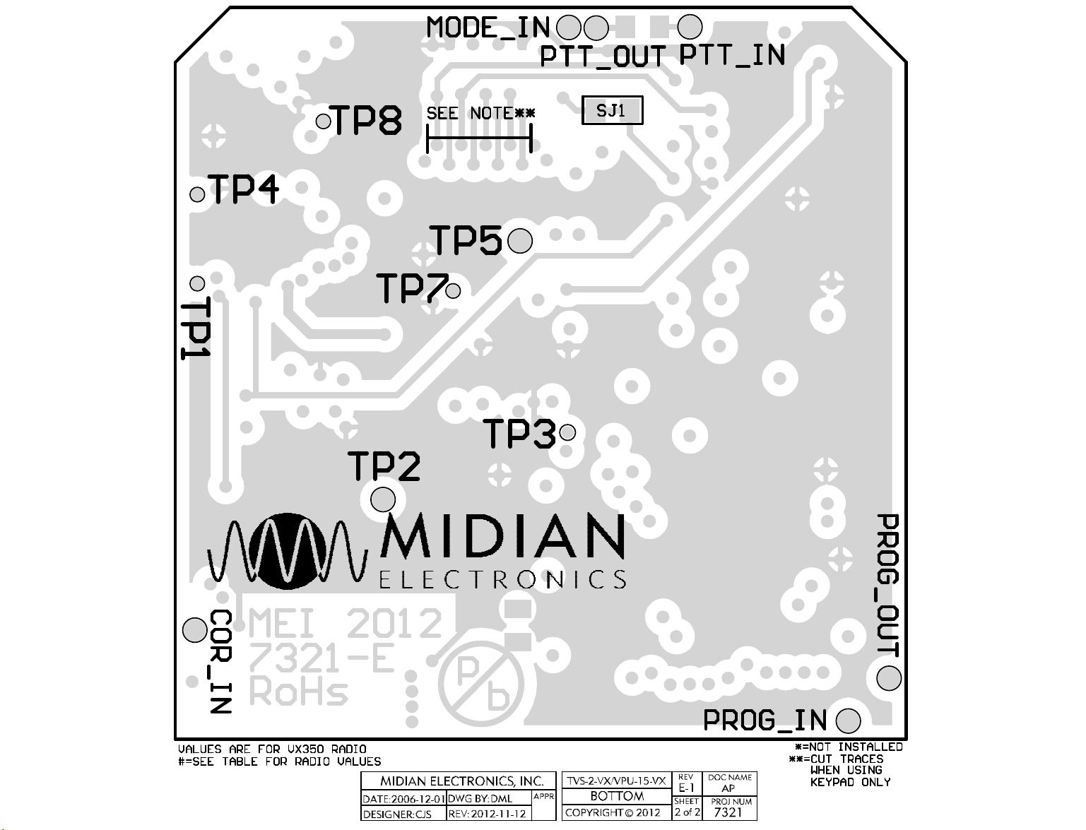
Programming: Plug the board onto the KL-4 and connect the green clip lead to the Prog In* hole. Push and hold
the power button on the KL-4 and click “Program Unit” in the MPS software. The ACK LED on the KL-4 will flash
if programmed successfully.
Reading: Plug the board onto the KL-4, connect the green clip lead to the Prog In* hole, and connect the yellow
clip lead to the Prog Out* hole. Push and hold the power button on the KL-4 and click “Read Unit” in the MPS
software.
NOTE: When the scrambler is read, the security codes will be read out as zeroes. If another scrambler is then
cloned with this information, the scramblers will be incompatible because they have different security codes.
*Please reference the pictorial at the end this manual for location of programming connections.*
3
Page 4

HARDWARE INSTALLATION
Be certain to follow standard anti-static procedures when handling any of Midian’s products.
VX-350: Remove the battery, exposing the option board cover and remove the cover. Plug the scrambler onto
the options connector. Replace the option board cover and battery. The scrambler requires this radio have
firmware version 1.0 or higher.
VX-410 & VX-420: Remove the battery, exposing the option board cover and remove the cover. Remove the
dummy board from the radio and replace with the scrambler. Replace the option board cover and battery. The
scrambler requires this radio have firmware version 1.04 or higher.
VX-450 & VX-460: Remove the battery, exposing the option board cover and remove the cover. Plug the
scrambler onto the Options Connector. Replace the option board cover and battery. The scrambler has been
tested in firmware version 1.10.00.00.
VX-600 & VX-900: Remove the battery, exposing the option board cover and remove the cover. Remove the
dummy board from the radio and replace with the scrambler. Replace the option board cover and battery. The
scrambler requires this radio have firmware version 1.22 or higher.
VX-800: Remove the battery, exposing the option board cover and remove the cover. Remove the dummy board
from the radio and replace with the scrambler. Replace the option board cover and battery. The scrambler
requires this radio have firmware version 1.28 or higher.
VX-820/920: Remove the battery, exposing the option board cover and remove the cover. Plug the scrambler
onto the options connector. Replace the option board cover and battery. The scrambler requires this radio have
firmware version 1.19 or higher.
VX-2100/VX-2200: Remove the cover of the radio exposing the options connector. Plug the scrambler onto the
Options Connector. Replace the cover of the radio. The scrambler has been tested in firmware version 1.00.
Note: Some versions of this radio may have a large diode (D1002) installed under the options connector that can
cause a short on the unit. If this diode is present protect the option board using electrical or kapton tape.
VX-4100/VX-4200: Remove the cover of the radio exposing the options connector. Plug the scrambler onto the
Options Connector. Replace the cover of the radio. The scrambler has been tested in firmware version 1.25.
VX-4500/VX-4600: Remove the cover of the radio exposing the options connector. Plug the scrambler onto the
Options Connector. Replace the cover of the radio. The scrambler has been tested in firmware version
1.10.00.00.
VX-4000, VX-5500 & VX-6000: Remove the cover of the radio exposing the options connector. Plug the FIF-7A
(from Vertex) onto the options connector per Vertex’s instructions. Then plug the scrambler onto the FIF-7A.
Replace the cover of the radio. The scrambler requires firmware version 2.02 or higher in the VX-4000. The VX5500 has been tested with firmware version 0324. The VX-6000 has been tested with firmware version 4.02.
NOTE: The scrambler should be ordered for the specific radio model. However, if you need to change radio
models please see the tables under technical notes at the end of this manual for necessary component changes.
4
Page 5

RADIO PROGRAMMING
VX-350:
For the VX-350 radio programming software CE-86 v1.01 or higher must be used.
Read the radio with the option board installed. Select “Common” from the menu and then “Option”. The “Option
Unit” should be read as “FVP-35”.
Under the “Common” heading select “Key Function” to set which key will control scramble on/off. Set the mode
select button to “Option Switch” or “Option Switch 2”.
Download the program to the radio.
VX-410 & VX-420:
For the VX-410 & VX-420 radio programming software CE-64 v1.00 or higher must be used.
Read the radio with the option board installed. Select “Common” from the menu and then “Option”. Set the
“Option Board” to “Encryption (Hi Level)”.
Under the “Common” heading select “Key Function” to set which key will control scramble on/off. Set the “Side 1”
or “Side 2” Key to “ACC 1”. Press or Press & Hold may be used. The assigned button will then control scramble
on/off and/or code select. On full keypad versions the A, B, C, or D button may be used.
In the main screen, in the “ENCR” column, every channel must have the flag checked. NOTE: This does not
provide encryption on a per channel basis. On this screen, the “SQ” column must have a figure greater than “0”.
Download the program to the radio.
VX-450 & VX-460:
For the VX-450 & VX-460 radio programming software CE-115 v1.01 or higher must be used.
Read the radio with the option board installed. Select “Common” from the menu and then “Option”. The “Option
Unit” should be read as “FVP-35”.
Under the “Common” heading select “Key Function” to set which key will control scramble on/off. Set the mode
select button to “Option Switch 1”.
Download the program to the radio.
VX-600 & VX-900:
For the VX-600 & VX-900 radio programming software CE-39 v1.04 or higher must be used.
Read the radio with the option board installed. Select “Common” from the menu and then “Miscellaneous”. Set
the “Encryption Type” to “Hi Level”. This will also change the “Encryption Device” setting under “Common” >
“Option” to “Yes”.
Under the “Common” heading select “Key Function” to set which key will control scramble on/off. Set the “TOP
SEL Key” (top orange button), “SIDE SEL Key” (top side button), or the A, B, C, or D (keypad models only) button
to “ACC1”. The assigned button will then control scramble on/off and/or code select.
In the main screen, in the “ENCR” column, every channel must have the flag checked. NOTE: This does not
provide encryption on a per channel basis.
Download the program to the radio.
5
Page 6

VX-800:
For the VX-800 radio programming software CE-31 v1.20 or higher (DOS) or v1.05 (Windows) must be used.
Read the radio with the option board installed. Select “Common” from the menu and then “Miscellaneous”. Set
the “Encryption Type” to “Hi Level”. This will also change the “Encryption Device” setting under “Common” >
“Option” to “Yes”.
Under the “Common” heading select “Key Function” to set which key will control scramble on/off. Set the “SEL1
Key” (top orange button), “SEL2 Key” (top gray button), or the A, B, C, or D (keypad models only) button to
“ACC1”. The assigned button will then control scramble on/off and/or code select.
In the main screen, in the “ENCR” column, every channel must have the flag checked. NOTE: This does not
provide encryption on a per channel basis.
Download the program to the radio.
VX-820 & VX-920:
For the VX-820/920 radio programming software CE-59 v2.10 or higher must be used.
Read the radio with the option board installed. Select “Common” from the menu and then “Option”. The “Option
Unit” should be read as “FVP-35”.
Under the “Common” heading select “Key Function” to set which key will control scramble on/off. Set the mode
select button to “Option SW1” or “Option SW2”. Option SW1 is momentary and Option SW2 is latched.
Download the program to the radio.
VX-2100 & VX-2200:
For the VX-2100 & VX-2200 radio programming software CE-82 v1.04 or higher must be used.
Read the radio with the option board installed. “Key Function” to set which key will control scramble on/off. Set
the “P1-P4 Short Press” button to “Option SW”.
Download the program to the radio.
VX-4100 & VX-4200:
For the VX-4100 & VX-4200 radio programming software CE-59 v1.01 or higher must be used.
Read the radio with the option board installed. Select “Common” from the menu and then “Option”. The “Option
Unit” should be read as “FVP-35”.
Under the “Common” heading select “Key Function” to set which key will control scramble on/off. Set the “P1-P4”
or “A” button to “Option Switch 1”.
Download the program to the radio.
6
Page 7

VX-4500 & VX-4600:
For the VX-4500 & VX-4600 radio programming software CE-115 v1.01 or higher must be used.
Read the radio with the option board installed. Select “Common” from the menu and then “Option”. The “Option
Unit” should be read as “FVP-35”.
Under the “Common” heading select “Key Function” to set which key will control scramble on/off. Set the “P1-P4”
or “A” button to “Option Switch 1”.
Download the program to the radio.
VX-4000, VX-5500 & VX-6000:
For the VX-4000 radio programming software CE-35 v2.0.2.0 or higher or CE-49 v3.3.0.0 or higher must be used.
For the VX-5500/VX-6000 radio programming software CE-49 v3.3.0.0 or higher must be used.
Read the radio with the option board installed. Select “Common” from the menu and then “Option”. Set the
“Option Unit” to “FVP-35 (Hi Level Encr)”. This will also change the “Encryption Type” setting under “Common” >
“Miscellaneous” to “Hi Level”.
Under the “Common” heading select “Key Function” to set which key will control scramble on/off. Set the PF1PF5 (long or short) button to “Hi-Level Encr SW”. If the short press is selected only scramble on/off is available.
If the long press is selected scramble on/off and code select are available.
In the main screen, in the “ENCR” column, every channel must have the flag checked. NOTE: This does not
provide encryption on a per channel basis.
Download the program to the radio.
7
Page 8

OPERATION
Radio
C3 C4 C9
C20 C21 R1 R2 R6 R7 R15 R18 R19
Mode Select: Press the radio key that was assigned in the radio programming. A tone followed by a higher tone
indicates the unit was toggled into scramble mode. A tone followed by a lower tone indicates the unit was toggled
into clear mode.
Code Select: When the unit is programmed with multiple security keys, pressing and holding the mode button
can access different keys. A number of tones will be emitted as the unit changes from one code to another.
TECHNICAL NOTES
Radio Compatibility: Midian has taken the utmost care to ensure the option board integrates into the radio with
minimal impact to the features of the radio. However, some features may not be available in the radio when an
option board is used.
VX-4000: Go-Ahead beeps are not supported in this radio.
NOTE: The scrambler should be ordered for the specific radio model. However, if you need to change radio
models you will need to complete the component changes on the following list.
TVS-2-VX & VPU-15-VX REVISION C & D
VX-350 222 222 103 222 222 750 K 220 K 47 K 47 K 47 K 750 K 200 K
VX-410/420 222 222 103 222 222 1 M 220 K 62 K 47 K 47 K 220 K 220 K
VX-450/460
VX-4500/4600
VX-600/900/
2100/2200/4000/
5500
VX-800 222 222 103 222 222 1 M 470 K 62 K 47 K 75 K 200 K 220 K
VX-820/920 222 103 104 222 104 750 K 47 K 47 K 47 K 62 K 750 K 750 K
VX-4100/4200 222 103 104 223 103 1 M 470 K 62 K 47 K 75 K 470 K 150 K
VX-6000 222 103 104 222 222 560 K 220 K 62 K 36 K 47 K 750 K 750 K
102 102 104 472 222 560 K 470 K 62 K 47 K 75 K 100 K 270 K
222 222 103 222 222 1 M 220 K 47 K 47 K 47 K 200 K 62 K
MIDIAN ELECTRONICS, INC.
2030 N. Forbes Blvd. #101
Tucson, Arizona 85745 USA
Toll-Free: 1-800-MIDIANS
Main: 520-884-7981
E-mail: sales@midians.com
Web: www.midians.com
MIDIAN CONTACT INFORMATION
8
Page 9

1
1
2
2
3
3
4
4
5
5
6
6
D D
C C
B B
A A
CP
CJS
2006-12-01 DML
2012-11-12
E-1
1 of 1
7321
MIDIAN ELECTRONICS, INC.
DATE:
DESIGN:
DWN BY:
REV:
APPR
COPYRIGHT ©
REV
SHEET
PROJECT NUMBER
DOCUMENT NAME
SCHEMATIC
2012
TVS-2-VX/VPU-15-VX
GND
P1:1
NOT USED
P1:2
PTT_IN
P1:3
+VB[NU]
P1:4
NOT USED
P1:5
NOT USED
P1:6
NOT USED
P1:7
MODE_IN
P1:8
AUDIO SWITCH
P1:9
COR IN
P1:10
NOT USED
P1:11
NOT USED
P1:12
NOT USED
P1:13
RX_OUT
P1:14
PTT_OUT
P1:15
RX_IN
P1:16
ENABLE
P1:17
TX_OUT
P1:18
NOT USED
P1:19
TX_IN
P1:20
NOT USED
P1:21
P1:22
P1:23
P1:24
P1:25
P1:26
P1:27
P1:28
P1:29
P1:30
P1:31
P1:32
P1:33
P1:34
P1:35
P1:36
P1:37
P1:38
GND
P1:39
+3.5V(SW)
P1:40
100K
R23
100K
R24
100K
R25
100K
R26
3.5V
OSC2
36
TCMP
33
VDD
38
VPP
43SS32
B3
11
D7
34
OSC1
37
B0
8
B1
9
A5
2
A6
1
A7
44
A43A34A25A16A0
7
C4
21
C5
20
C3
23
C0
26
C1
25
C2
24
C6
19
C7
18
B4
12
B7
15
B6
14
GND
17
RES
41
B2
10
TCAP
35
IRQ
42
B5
13
SCK
31
MOSI
30
MISO
29
RDI
27
TDO
28
NC1
16
NC2
22
NC339NC4
40
MC705C8
U1
SD1
D1
3.5V 3.5V
.47u
C1
CS
1
SCLK
2
SI
3
SO
4
VCC
8
NC1
7
NC2
6
GND
5
CAT93C46
U2
.1u
C32
3.5V
PAD1
PTT_IN
PAD7
PTT_OUT
PAD2
MODE_IN
PAD6
COR_IN
560p
C7
*
RJ1
-
+
2
3
1
LM358
U8:1
-
+
6
5
7
LM358
U8:2
8
VCCVCC
4
GNDGND
LM358
U8:3
.0022u
C3
39p
C34
1.2M
R3
VAN
4.7K
R28
.0068u
C5
TP4
3
V+V+2OUTOUT
1
GNDGND
MAX809-S
U9
560p
C2
100K
R17
3.5V 3.5V
A11A
11
X012X0
12
X113X1
13
X14X
14
74HC4053
U3:1
B10B
10
Y11Y1
1
Y02Y0
2
Y15Y
15
74HC4053
U3:2
C9C
9
Z4Z
4
Z05Z0
5
Z13Z1
3
E\6E\
6
VCC16VCC
16
VEE7VEE
7
GND8GND
8
74HC4053
U3:3
.47u
C29
12K
R4
3.5V
39p
C6
1.2M
R27 TP1
VAN
750K
R1
BSS
Q1
100K
R5
-
+
2
3
1
LMV324
U7:1
-
+
6
5
7
LMV324
U7:2
-
+
9
10
8
LMV324
U7:3
-
+
13
12
14
LMV324
U7:4
4
VCCVCC
11
GNDGND
LMV324
U7:5
VAN
10K1%
R8
10K1%
R9
100p
C10
VAN
36K
R10
OSC1
18
OSC2
17
A4
3
A0
19
A1
20
MCLR
4
VDD
15
VDD
16
VSS5VSS
6
B6
13
B7
14
B18B29B3
10
B4
11
B0
7
B5
12
A21A3
2
16F716
U5
3.5V
27K
R11
8.2K
R12
.0068u
C11
.0068u
C12
56K
R13
VAN
36K
R14
1.2M
R16
.001u
C13
VAN
TP2
SHDN
7V+4
CLK
8
IN
2
OUT
5
COM1OS
6
V-
3
MAX7427
U4
.47u
C15
39p
C14
TP3
3.5V
560p
C16
VAN
TP8
1
VSVS
2
GNDGND
3
OUTOUT
4
TRGTRG
5
THSTHS
MIC555
U6
22p
C26
82p
C25
39p
C24
150p
C23
470p
C22
4.7K
R20
.01u
C33
3.5V
750K
R18
.0022u
C20
220p
C19
*
C18
TP7
TP5
22p
C28
22p
C27
3.58 MHz.
Y1
4.7M
R21
PAD3
PROG_IN
PAD4
PROG_OUT
SJ1
10K
R22
3.5V
3.5V 3.5V
1
2
3
4
5
6
7
8
U4B
*
4.7u
C17
*
C38
.1u
C37
*
UK1
CUT LINES ON PCB ONLY WHEN USING KEYPAD
(SOURCE)
.0022u
C4
.01u
C9
.0022u
C21
220K
R2
47K
R6
47K
R7
47K
R15
200K
R19
COU9
PIU808
PIU804
PIP104
COP1:4
PIP109
COP1:9
PIP101
COP1:1
PIP1039
COP1:39
COU8:3
COP1:40
COP1:20
COP1:16
PIU704
PIU7011
PIP1040
PIP1020
PIP1016
COU7:5
PIC201
COC2
PIC202
PIU901
PIU902PIU903
PIC301 PIC302
PIC401 PIC402
PIP1015
COP1:15
PIPAD701
COPAD7
CORJ1
PIP103
PIP108
PIP1010
PIU806
PIU805
PIU802
PIU803
PIRJ101
PIC701
COC7
PIC702
COC34
PIC3401 PIC3402
COR3
PIR301
PIU807
COU8:2
COC6
PIC601 PIC602
COR27
PIR2701
COU8:1
PIR1701
COR17
PIR1702
COC3
PIR201 PIR202
COC4
PIR101 PIR102
COPAD1
COP1:3
COPAD2
COP1:8
COPAD6
COP1:10
COR2
COR1
PIPAD101
PIPAD201
PIPAD601
PIRJ102
PIR302
PIR2702
PIU801
COP1:22
COTP4
COR28
PIR2801 PIR2802
PITP101
COTP1
COD1
PIP1022
PITP401
COP1:24
COP1:23
COP1:26
COP1:25
COP1:28
COP1:27
COP1:30
PID101PID102
COP1:29
COP1:32
COP1:31
COP1:34
COP1:33
COP1:36
COP1:35
COP1:38
COP1:37
PIC501
COC5
PIC502
PIP1024
PIP1023
PIP1026
PIP1025
PIP1028
PIP1027
PIP1030
PIP1029
PIP1032
PIP1031
PIP1034
PIP1033
PIP1036
PIP1035
PIP1038
PIP1037
PIU305
PIU303
PIR1101
COR11
PIR1102
PIR1201
COR12
PIR1202
PIU309
PIU3016
PIU306
COC11
PIC1101 PIC1102
COC12
PIC1201 PIC1202
PIR2301
PIR2302
COU3:3
PIU304
PIU308
PIU307
PIR2401
COR23
COR24
PIR2402
PIC2901
COC29
PIC2902
COR4
PIR401 PIR402
COR13
PIR1301
PIU709
PIU7010
COU7:3
PIR2501
PIR2601
COR25
COR26
PIR2502
PIR2602
COC9
PIC901 PIC902
PIC1001
COC10
PIC1002
PIR1302
PIR1401 PIR1402
PIU708
PIR501
COR5
PIR502
PIQ10G
PIQ10D
PIQ10S
COQ1
COR7
PIR701 PIR702
PIU702
PIU703
COU7:1
PIU706
PIU705
COU7:2
COR15
PIR1501 PIR1502
COR14
COR6
PIR601 PIR602
PIC3201
COC32
PIC3202
PIU701
PIR801
PIR802
PIR901
PIR902
PIU707
PIR1601 PIR1602
PIU7012
PIU7013
PIC1301
COC13
PIC1302
PIU208
PIU207
PIU206
COU2
COR8
COR9
COR16
COU7:4
PIU201
PIU202
PIU203
PIU204PIU205
PIU5015
PIU5016
PIU5019
COU5
PIR1002
COR10
PIR1001
PIU301
PIU302
COU3:2
PIU7014
PIU1023
PIU1025
PIU1021
PIU1020
PIU1019
PIU1026
PIU1024
PIU1010
PIU101
PIU102
PIU1034
PIU1011
PIU1031
PIU1030
PIU1029
PIU1041
PIU1015
PIU1014
PIU1044
PIU1033
PIU3010
PIU3015
PIUK102
COUK1
PIUK101
PIU1042 PIU1043
PIU103 PIU104 PIU105 PIU106 PIU107
PIU1035
COTP3
PIC1402
PIC1401
PITP201
COTP2
PIU1032
PIU1038 PIU1039PIU1040
COU1
PIU508 PIU509
PIU505 PIU506PIU507
PIU5017
PITP301
PIU402
COC14
PITP801
COTP8
PIC101
PIC102
PIU1012
PIU1017
PIU1013
PIU1016
PIU1018
PIU1027
PIU1022
PIU1028
PIU109
PIU108
PIU1037
PIU1036
PIU5010PIU5011 PIU5012PIU5013
PIU5018
PIU5014
PIU407PIU408
COU4
PIU401
PIU406
PIC1601
PIC1602
COC1
PIR2101
COR21
PIR2102
PIU503PIU504
PIU5020
PIU501
PIU502
PIU404
PIU405
PIU403
PIC1701
COC16
PIC1702
PIY102
COY1
PIY101
PIC2601 PIC2602
PIC2501 PIC2502
PIC2401 PIC2402
PIC2301 PIC2302
PIC1501
COC15
PIC1502
COTP5
PITP501
COU4B
PIU4B04
PIU4B03
PIU4B06 PIU4B07
PIC3701
COC17
PIC3702
PIC2802
COC28
PIC2801
PIC2702
COC27
PIC2701
COC26
COC25
COC24
COC23
PIU4B02
PIU4B05
PIU4B01
PIC3801
COC37
PIC3802
PIC2201
COC22
PIC2202
PIU3014
PIU4B08
COC38
PIU3011
COU3:1
PIR2201
COR22
PIR2202
PIR2002
PIR2001
PIU3012
PIU3013
PIU604
PIU605
COU6
COR20
COR18
PIR1801 PIR1802
COR19
PIR1901 PIR1902
COSJ1
PISJ101 PISJ102
PIU601
PIU602
PIC1901
PIC1902
PIC1801
PIC1802
PIU603
COC19
COC18
PIC3302
COC33
PIC3301
COC20
PIC2001 PIC2002
COC21
PIC2101 PIC2102
PIPAD301
PIPAD401
PIP1017
COP1:17
PIP1018
COP1:18
PITP701
PIP1014
COP1:14
COPAD3
COPAD4
COTP7
PIP102
PIP105
PIP106
PIP107
PIP1011
PIP1012
PIP1013
PIP1019
PIP1021
COP1:2
COP1:5
COP1:6
COP1:7
COP1:11
COP1:12
COP1:13
COP1:19
COP1:21
COtb0sch1
Page 10

-This Page Intentionally left Blank-
Page 11

COVO5
COR20
PAR2002 PAR2001
PAU604
PAU605
PAC2602
PAC2302
PAC2402
COC23
COC24
PAC2301
PAC2401
PAU501
PAU502
PAU503
PAU504
PAU505
PAU506
PAU507
PAU508
PAU509
PAU5010 PAU5011
COC26
PAC2601
COU5
PAU1011
PAU1012
PAU1013
PAU1014
PAU1015
PAU1016
PAU1017
PAU1018
PAU1019
PAU1020
PAU1021
PAU1022
COR26
PAR2602PAR2601
COR25
PAR2501 PAR2502
PAU603
COU6
COR24
PAU602
PAU601
PAC2201
COC22
PAC2202
COtb0sch1
PAU1010
PAU109 PAU108 PAU107 PAU106 PAU105 PAU104 PAU103 PAU102 PAU101
COU1
PAR2402PAR2401
COR23
PAR2301 PAR2302
PAC3302
PAC2502
COC25
PAC3301
PAC2501
PAVO501
COC33
PAU5020
PAU5019
PAU5018
PAU5017
PAU5016
PAU5015
PAU5014
PAU5013
PAU5012
PAU1023
COC7
PAC701 PAC702
PAVO503
PAVO505
PAVO507 PAVO509
PAVO5011
PAP109PAP107PAP105PAP103PAP101
COP1
PAVO5012
PAVO5010
PAVO508
PAVO506
PAVO504
PAP102 PAP104 PAP106 PAP108
COR10
PAR1002
PAC1701
PAP1010 PAP1012 PAP1014 PAP1016 PAP1018 PAP1020 PAP1022 PAP1024 PAP1026 PAP1028 PAP1030 PAP1032 PAP1034 PAP1036 PAP1038 PAP1040
PAR1001
COC17
PAU4B01
COD1
PAD101
PAVO5013 PAVO5015
PAVO5017
PAVO5019
PAVO5020
PAVO5018
PAVO5016PAVO5014
PAU407PAU408
PAC1702
PAC1401
PAC1402
PAU4B02
COC14
PAU4B03
COU4B
PAU401 PAU402
PAU4B04 PAU4B05
PAU403 PAU404
PAC3701
PAC3702
PAR2202
COR22
PAR2201
PAU1033PAU1032PAU1031PAU1030PAU1029PAU1028PAU1027PAU1026PAU1025PAU1024
PAVO5044
PAU1044
PAVO5043
PAU1043
PAVO5042
PAU1042
PAVO5041
PAU1041
PAU1040
PAU1039
PAU1038
PAU1037
PAU1036
PAU1035
PAU1034
COC2
PAC201
PAD102
PAVO5021 PAVO5023
PAVO5025
PAVO5027
PAVO5028
PAVO5026
PAVO5024PAVO5022
PAU405PAU406
PAU4B08
COU4
PAU4B07
PAU4B06
PAC202
PAVO5029 PAVO5031
PAVO5033
PAVO5035 PAVO5037
PAVO5039
PAP1039PAP1037PAP1035PAP1033PAP1031PAP1029PAP1027PAP1025PAP1023PAP1021PAP1019PAP1017PAP1015PAP1013PAP1011
PAVO5040
PAVO5038PAVO5036
PAVO5034
PAVO5032PAVO5030
PAC1901
PAC2001
COC20
COC19
PAC1902
PAC2002
COC21
PAC2102
COC18
COC29
PAC2902 PAC2901
PAC1101
COC11
PAC1102
PAC1501
PAC3801
COC37
COC38
PAC3802
COC1
PAC102
PAC101
PAR1702
COU9
COR17
COR13
COC15
PAR1302
COR14
PAC1502
COC13
PAC1302
PAC1301
PAU902
PAU903
PAR1701
PAVO502
PAY102
PAU901
COY1
PAY101
COC28
PAR2101
COR21
PAR2102
PAC2801
PAC2802
COC27
PAC2702
PAC2701
COC6
PAC601
COC3
PAC301
PAC602
PAR2702
COR27
PAR2701
COR1
PAR102
PAR101
COC4
PAC401 PAC402
COR18
PAR1802
PAR1801
COR19
PAR1901PAR1902
PAC2101
PAR1101
COR11
PAC1801PAC1802
PAR1102
COR12
PAR1201
PAC1201
PAU708
COC12
PAU709
PAC1202
PAU7010
PAU7011
PAR1301
PAU7012
PAU7013
PAR1402PAR1401
PAU7014
COR16
PAR1602 PAR1601
COC16
PAC1602
PAU201
PAU202
PAU203
PAR1502
PAR1501
PAC1601
COU2
COR2
PAC302
PAR201
PAU801
COU8
PAU802
PAU803
PAU804 PAU805
COC34
PAC3401 PAC3402
COR3
PAR301 PAR302
PAU3010
PAU3011
PAU3012
PAU3013
PAU3014
PAU3015
PAUK102
COUK1
COC10
PAUK101
COR9
PAR1202
COU7
COR15
PAVO50D
PAQ10D
PAR202
PAU808
PAU807
PAU806
PAC502
COR28
PAU309 PAU308
COU3
PAU3016
PAU301
PAR801
PAC1001PAC1002
PAR901PAR902
PAR802
PAU707
PAU706
PAU705
PAU704
PAU703
PAU702
PAU701
PAVO50S
PAQ10S
COQ1
PAVO50G
PAQ10G
PAU208
PAU207
PAU206
PAU205PAU204
COC5
PAR2802PAR2801
PAC501
PAU307
PAU306
PAU305
PAU304
PAU303
PAU302
PAR401
COR4
COR8
PAR402
PAC901
COC9
PAC902
COR7
PAR701
PAR702
PAR602
COR6
PAR601
PAR502
COR5
PAR501
PAVO50GND
PAY10GND
PAC3201
COC32
PAC3202
Page 12
COVO6
PATP801
COTP8
COPAD2
COPAD7
CORJ1
PAPAD201
PAPAD701
COSJ1
PAVO602 PAVO601
PASJ102 PASJ101
PARJ101PARJ102
COPAD1
PAPAD101
PATP401
PATP101
COTP4
COVO4
COTP1
COtb0sch2
COPAD6
PATP701
COTP7
COTP2
PATP201
PATP501
COTP5
PATP301
COTP3
PAPAD601
COPAD4
PAPAD401
COPAD3
PAPAD301
 Loading...