

Page 1

VPU-12A
16-Code Voice Inversion Scrambler
Manual Revision: 2013-04-01
Covers Software Revisions:
VPU-12A: 3.0 and higher
1
Page 2

SPECIFICATIONS
Operating Voltage +3.7-15 VDC
Operating Current 3.5 mA
Operating Temperature -30 - +60 C
Frequency Response – 2100 Hz 300-1700 Hz
Frequency Response – 3100 Hz 300-2500 Hz
Frequency Response – 4100 Hz 300-3600 Hz
Audio Output Impedance <10K
Input Level 150-1000 mV p-p
Input Impedance >60K
Frequency Error <0.25%
Device Gain or Loss Unity
Inversion Frequency Range 2100 – 4100 Hz
Number of Inversion Codes 16
GENERAL INFORMATION
Midian’s VPU-12A voice inversion scrambler provides an entry level of voice security for two-way radio
communications. The VPU-12A provides up to 16 different inversion frequencies that are selectable using 4-line
binary. These inversion frequencies are programmable using Midian’s KL-3. The VPU-12A is compatible with
Midian’s VPU-12, but adds the benefit of mode indications.
2
Page 3

PRODUCT PROGRAMMING
The VPU-12A comes preprogrammed with default inversion frequencies (see Table 1 below). By configuring the
4-line binary outputs, the desired inversion frequency can be selected. Other default features are a Power-Up
State of Clear, a Mode Select of Momentary and a Mode Polarity of Active Low. If different parameters are
needed, the KL-4 programming interface and MPS programming software will be needed.
Table 1
Grounded Wires –
Frequency Select
(A, B, C, D)
Org/Wht, Gray, Gray/Wht, Grn/Wht 0000 1 2100
Org/Wht, Gray, Gray/Wht 0001 2 2341
Org/Wht, Gray, Grn/Wht 0010 3 2423
Org/Wht & Gray 0011 4 2587
Org/Wht, Gray/Wht, Grn/Wht 0100 5 2632
Org/Wht, Gray/Wht 0101 6 2728
Org/Wht, Grn/Wht 0110 7 2868
Org/Wht 0111 8 2976
Gray, Gray/Wht, Grn/Wht 1000 9 3023
Gray, Gray/Wht 1001 10 3107
Gray, Grn/Wht 1010 11 3333
Gray 1011 12 3388
Gray/Wht, Grn/Wht 1100 13 3500
Gray/Wht 1101 14 3729
Grn/Wht 1110 15 4096
None 1111 16 3276
The VPU-12A is programmed using the KL-4 programming interface and MPS programming software. Please
reference the KL-4 manual for setup of the programming hardware and software.
Set the parameters of the software to fit the application. If any clarifications on a feature are required, move the
mouse cursor over the feature name until the question mark appears and right click, a definition of the feature will
be shown.
After entering the parameters, save the file by going to File - Save As. Enter the file name in the File Name block
and click Save. Saving the file will allow for quick and easy reprogramming of units.
KL-4 Programming: Plug the board onto the KL-4 connector labeled as “P4”. Push and hold the power button
on the KL-4 and click “Program Unit” in the MPS software. The ACK LED on the KL-4 will faintly flash if
programmed successfully.
KL-4 Reading: Plug the board onto the KL-4 connector labeled as “P4”. Push and hold the power button on the
KL-4 and click “Read Unit” in the MPS software.
Binary Code # Inversion
Frequency
(Hz)
3
Page 4
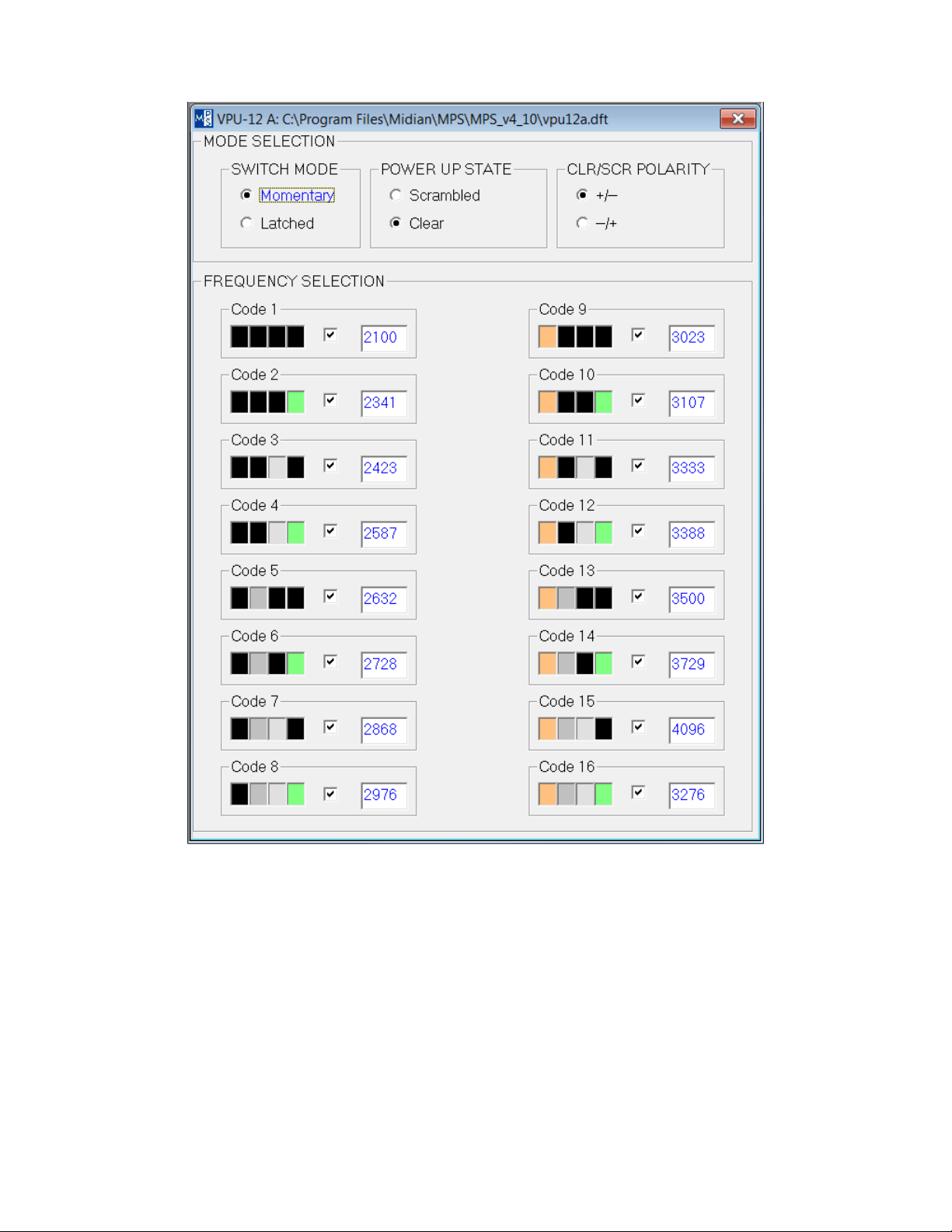
Switch Mode: Select whether the switch being used for mode selection is a momentary or latched switch.
Power Up State: Select the mode you wish the scrambler to go into upon power up.
Clr/Scr Polarity: If +/- is selected then the clear mode will be a positive polarity and scramble mode will be a
negative polarity. If -/+ is selected then the clear mode will be a negative polarity and scramble mode will be a
positive polarity.
Code 1-16: Set the desired inversion frequency for each code position. The table on the previous page shows
which code is selected based upon which 4-line binary inputs are selected. If only one code is being used,
program that code in Code 16 and do not connect any of the 4-line binary inputs.
4
Page 5

HARDWARE INSTALLATION
Be certain to follow standard anti-static procedures when handling any of Midian’s products.
P1-4 – Black – Ground – Connect to the nearest ground point.
P1-2 – Red - +3.7 – 15 VDC – Connect to switched B+ in the radio.
P1-6 – Orange – RX Input – Connect after the CTCSS high-pass filter in radios using CTCSS or DCS. Failure to
do so will cause the CTCSS to be inverted from a low to a high frequency. Other signaling tones that might be
used on the system should be decoded before the scrambler input. The audio path should be broken with this
lead connected to the break point closest to the discriminator.
P1-13 – Violet – RX Output – Connect to the break point described in the RX Input on the side closest to the
speaker.
P1-9 – White – TX Input – Connect to the radio modulator circuit before the insertion point for CTCSS or other
tone signaling. The audio path is broken and this lead is connected to the break point closest to the microphone.
P1-1 – Green – TX Output – Connect to the break point described in TX Input on the side closest to the
modulator.
P1-7 – Yellow – PTT Input – Selection of the RX or TX path is provided via this lead. A ground from the PTT
switch will select TX & releasing the ground will select RX.
P1-3 – Brown – Mode Input/Program Out – Connect to a momentary or latched switch for selection of scramble
or clear modes. For program out, connect this lead to the yellow clip lead from the KL-3.
P1-5 – Blue – Program In – Connect this wire to the green clip lead from the KL-3.
P1-8 – Green/White – Frequency Select A – Frequency select A, B, C and D are used to determine the selected
inversion frequency (see Table 1 above).
P1-10 – Gray/White – Frequency Select B – Frequency select A, B, C and D are used to determine the selected
inversion frequency (see Table 1 above).
P1-11 – Gray – Frequency Select C or Mode LED – Frequency select A, B, C and D are used to determine the
selected inversion frequency (see Table 1 above).
When used for Mode LED install R-34 and remove D4. Connect this wire to the cathode of the LED and connect
the anode of the LED to V+. The Mode LED output provides an active low.
P1-12 – Orange/White – Frequency Select D or Audio Enable – Frequency select A, B, C and D are used to
determine the selected inversion frequency (see Table 1 above).
When used for Audio Enable install R-36 and remove D-3. Connect this wire to a point in the radio that when
grounded turns on the audio amplifier.
Mode LED: If the frequency select lines are being used for inversion frequency selection, the Mode LED hole can
have a wire added. Connect this wire to the cathode of the LED and connect the anode of the LED to V+. The
Mode LED output provides an active low.
Audio Enable: If the frequency select lines are being used for inversion frequency selection the Audio Enable
hole can have a wire added. Connect this wire to a point in the radio that when grounded turns on the audio
amplifier.
5
Page 6

RADIO PROGRAMMING
The VPU-12A is a generic module that wires into most radios. Any radio specific programming, if available, would
be found on any Application Notes available for those radios. You may visit our website or call us for application
notes.
HARDWARE ALIGNMENT
The VPU-12A is a unity gain device. If for some reason more or less gain is needed adjust R-2, R-12, R-18 or R19 as needed. For the TX Input, Midian recommends having 1 V p-p at Pin 1 of IC-5. Adjusting R-2 will adjust the
level at Pin 1 of IC-5.
For the RX Input, Midian recommends having 1 V p-p at Pin 7 of IC-5. Adjusting R-12 will adjust the level at Pin 7
of IC-5.
For the TX Output, Midian recommends matching the level of the radio that is present at the TX Input (P1-9).
For the RX Output, Midian recommends matching the level of the radio that is present at the RX Input (P1-6).
6
Page 7

OPERATION
Mode Selection: The mode of the VPU-12A can be controlled by a momentary or latched switch.
Latched Switch: Programming the VPU-12A to latched with a Mode Polarity of +/- will cause the scrambler to
be in clear mode when high and scramble mode when taken to ground. A Mode Polarity of -/+ will cause the
scrambler to be in clear mode when taken to ground and scramble mode when high.
Momentary Switch: Programming the VPU-12A to momentary with a Mode Polarity of +/- will cause the
scrambler to toggle modes when taken to ground. A Mode Polarity of -/+ will cause the scrambler to toggle
modes when taken high.
Code Selection:
Single Code: If only a single inversion frequency is desired connect the frequency select lines to ground as
indicated in Table 1 above. Otherwise if no frequency select lines are grounded code 16 will be selected.
Multi-Code: The VPU-12A has a 4-line binary input that can be used to select from 16 different inversion
frequencies (see Table 1 above).
7
Page 8

TECHNICAL NOTES
Pre-emphasis/De-emphasis: The scrambler should be installed before pre-emphasis and after de-emphasis.
If installed after pre-emphasis and before de-emphasis, the recovered audio may be noisier due to the
amplification of the noise.
If installed before pre-emphasis and before de-emphasis, recovered audi o will be de-emp hasized (bassy).
If installed after pre-emphasis and after de-emphasis, recovered au dio is pre-emphasized (tinny).
MIDIAN CONTACT INFORMATION
MIDIAN ELECTRONICS, INC.
2302 East 22
nd
Street
Tucson, Arizona 85713 USA
Toll-Free: 1-800-MIDIANS
Main: 520-884-7981
E-mail:
HUsales@midians.comU
Web: HUwww.midians.comU
8
Page 9

1
1
2
2
3
3
4
4
5
5
6
6
D D
C C
B B
A A
CP
CJS
2007-07-01 DML
2013-04-05
A-3
1 of 1
7361
MIDIAN ELECTRONICS, INC.
DATE:
DESIGN:
DWN BY:
REV:
APPR
COPYRIGHT ©
REV
SHEET
PROJECT NUMBER
DOCUMENT NAME
SCHEMATIC
2013
VPU-12A
47K
R8
47K
R1
SD1
D1
3.3V
3.3V
RA2
1
RA3
2
TOCK1
3
MCRL
4
VSS5VSS
6
RB0
7
RB1
8
RB2
9
RB3
10
RB4
11
RB5
12
RB6
13
RB7
14
VDD15VDD
16
OSC2
17
OSC1
18
RA0
19
RA1
20
16LF818
IC1
TP3
560p
C11
100K
R21
100K
R2
560p
C29
.1u
C13
-
+
2
3
1
LMV324
IC5:1
-
+
6
5
7
LMV324
IC5:2
-
+
9
10
8
LMV324
IC5:3
-
+
13
12
14
LMV324
IC5:4
4
VCCVCC
11
GNDGND
LMV324
IC5:5
VAN
560p
C12
100K
R20
100K
R12
.1u
C14
VAN
A11A
11
X012X0
12
X113X1
13
X14X
14
4053
IC2:1
B10B
10
Y11Y1
1
Y02Y0
2
Y15Y
15
4053
IC2:2
C9C
9
Z4Z
4
Z05Z0
5
Z13Z1
3
E\6E\
6
VCC16VCC
16
VEE7VEE
7
GND8GND
8
4053
IC2:3
SD1
D2
BSS
Q2
560p
C3
18K
R13
12K
R14
.012u
C10
BSS
Q1
-
+
2
3
1
LMV358
IC3:1
-
+
6
5
7
LMV358
IC3:2
8
VCCVCC
4
GNDGND
LMV358
IC3:3
10K1%
R15
47K
R10
36K
R11
.001u
C9
10K1%
R16
.01u
C6
.01u
C4
100p
C22
SD1D3
SD1D4
SD1D6
SD1D5
BSS
Q3
BSS
Q4
47K
R33
330R
R37
3.3V TP1
MODE LED
*
R34
BSS
Q5
.1u
C28
220K
R35
*
R36
TP2
AUDIO EN
SHDN
7
V+
4
CLK
8
IN
2
OUT
5
COM
1OS6
V-
3
7427
IC4
.1u
C16
.1u
C15
VAN
.01u
C19
3.3V
.1u
C18
3.3V
47K
R23
3.3V
100K
R18
100K
R19
100K
R32
.01u
C25
4.7K
R30
220K
R31
.01u
C7
560p
C27
100K
R22
VAN
.1u
C1
VAN
560p
C26
100K
R17
.1u
C2
*
C30
5206
IN1
1
ENA
3
GND
2
RES
4
OUT
5
VR1
.1u
C8
.1u
C17
3.3V
3.3V3.3V
TX OUT[GRN]
P1:1
+3.7V to +15V[RED]
P1:2
CLR/SCR/PROG OUT[BRN]
P1:3
GND
P1:4
PROG IN[BLUE]
P1:5
RX IN[ORG]
P1:6
RX/TX[YEL]
P1:7
FS A[GRN/WHT]P1:8
TX IN[WHT]
P1:9
FS B[GRAY/WHT]P1:10
FS C/MODE LED[GRAY]P1:11
FS D/AUDIO EN[ORG/W]P1:12
RX OUT[VIO]
P1:13
.01u
C21
3.3V
10 MHz.
Y1
1K
R3
OSC1
OSC2
OSC1
OSC2
22p
C23
22p
C24
.01u
C20
VIN
VIN
FREQUENCY SELECT
**
***
** = TO USE MODE LED REMOVE D4 AND INSTALL R34
*** = TO USE AUDIO EN REMOVE D3 AND INSTALL R36
* = NOT INSTALLED
PIY101
PIY102
COR3
PIR301 PIR302
PIR801
COR8
COC13
COC14
PIC1401PIC1402
PIR802
PIR101
COR1
PIR102
COR2
PIR201
COR12
PIR1202
PIC302
COC3
PIC301
PIR202
PIR1201
COC11
PIC1101 PIC1102
COR21
PIR2101 PIR2102
PIIC502
PIIC503
COIC5:1
COC12
PIC1201PIC1202
COR20
PIR2001PIR2002
PIIC506
PIIC505
COIC5:2
COD2
PIQ20D
COQ2
PIQ20G
PIQ20S
PIIC501
PIIC507
PID201PID202
COD1
PID101PID102
PIP103
COP1:3
PIP105
COP1:5
PIC1301 PIC1302
PIP109
COP1:9
COP1:6
COP1:7
PIP106
PIP107
PIC2901
COC29
PIC2902
COY1
COTP3
PIIC2012
PIIC2013
COIC2:1
PIC2402
COC24
PIC2401
PIC2301
PIC2302
COIC1
PIIC101
PIIC103
PIIC107
PITP301
PIIC102
PIIC104
PIIC1017
PIIC1018
PIIC2011
PIIC2014
COC23
PIIC1015 PIIC1016
PIIC105 PIIC106
PIQ10G
PIC402
COC4
PIC401
COR13
PIC2101
COC21
PIC2102
PIIC1020
PIIC1019
PIIC1011
PIIC1012
PIIC1013
PIIC1014
PIIC108
PIIC1010
PIIC109
PIQ10D
COQ1
PIQ10S
PIR1301PIR1302
PIR1401 PIR1402
PIC1001
PIC1002
COR14
COC10
COD6
PID601 PID602
COD5
PID501 PID502
COD4
PID401 PID402
COD3
PID301 PID302
COR10
PIR1001 PIR1002
COR11
COC9
PIIC302
PIIC303
COIC3:1
PIC601
COC6
PIC602
PIP108
COP1:8
PIP1010
COP1:10
PIP1011
COP1:11
PIP1012
COP1:12
PIQ30G
PIR3302
COR33
PIQ40D
PIR3301
COQ4
PIQ40G
PIQ30D
PIQ40S
COQ3
PIQ30S
COR37
COTP1
PIR3701PIR3702
PITP101
PIR3401
COR34
PIR3402
PIR3501
COR35
PIR3502
PIQ50G
PIC2801
COC28
PIC2802
COTP2
PITP201
PIQ50D
PIR3602
COQ5
PIQ50S
PIR3601
COR36
PIR3102
PIR3201
COC7
PIR1801
COR31
PIR3101
PIC701
PIC702
PIIC509
PIIC5010
COC26
PIC2601PIC2602
COR17
PIR1701PIR1702
PIIC5013
PIIC5014
PIIC5012
COIC5:4
COC27
PIC2701 PIC2702
COR22
PIR2201 PIR2202
PIIC508
COIC5:3
COC30
PIC3001
PIC3002
COC2
PIC201 PIC202
PIC101 PIC102
COC1
PIP101
PIP1013
COP1:1
COP1:13
COIC2:3
PIIC2016
PIIC205
PIIC203
PIIC209
PIR2301
PIR2302
PIR3002
COR30
PIR3001
PIR3202
PIC2502
COC25
PIC2501
PIR1901 PIR1902
PIR1802
COR23
COR32
COR19
COR18
PIIC2010
PIIC201
PIR1101PIR1102
PIC901PIC902
PIIC301
COR15
PIR1601 PIR1602
PIIC306
PIR1501PIR1502
PIIC305
COR16
COIC3:2
PIIC307
PIIC202
COIC2:2
PIIC2015
PIC2202
PIC2201
PIC1602
COC16
PIC1601
PIIC402
COC22
PIC1502
COC15
PIC1501
PIC2002
COC20
PIC2001
PIIC407PIIC408
PIIC401
PIIC406
PIC1902
COC19
PIC1901
PIIC404
COIC4
PIIC405
PIIC403
PIC1801
COC18
PIC1802
PIIC204
PIIC208
PIIC207
PIIC206
COP1:4
PIP102
PIP104
PIC802
COC8
PIC801
PIVR101
PIVR103
COVR1
PIVR104
PIVR105
PIVR102
PIC1701
COC17
PIC1702
COtb0sch1
PIIC504
COIC5:5
PIIC5011
PIIC308
COIC3:3
PIIC304
COP1:2
Page 10

- This page intentionally left blank -
Page 11

Page 12

 Loading...