

Page 1

VAE-1-VX1
Voice Alarm Encoder
with Lone Worker and Man-Down
Manual Revision: 2013-04-03
Covers Software Revisions:
VAE-1: 01.53.00 & Higher
Covers Hardware Revisions:
VS-VX1: D & Higher
This manual & product supports the following Vertex radios:
Portables: VX-350, VX-410, VX-420, VX-450, VX-460, VX-600, VX-800, VX-820, VX-900, VX-920
Mobiles: VX-2100, VX-2200, VX-4000, VX-4100, VX-4200, VX-4500, VX-4600, VX-5500, VX-6000
1
Page 2

HARDWARE SPECIFICATIONS
Operating Voltage 4.75-9.5 VDC
Operating Current
Power Save Mode (COR Operation) 2.5 mA typical
Power Save Mode (VOX Operation) 10 mA typical
Repeat Operation 17.5 mA typical
Average w/COR Power Save (80-10-10 cycle) <5 mA
Average w/COR Power Save (90-5-5 cycle) <4 mA
Operating Temperature -30 - +60 C
Frequency Response 300-3000 Hz
Input Impedance >45 k
Input Level (TX) 0.05-2.5 VPP
Input Level (RX) 0.05-2.5 VPP
Audio Output Impedance < 1200 Ohm
INSTALLATION OVERVIEW
1. Test the radio for functionality.
2. Program the unit per the Product Programming Section of this manual.
3. Install the unit into the radio per the Hardware Installation Section of this manual.
4. Program the radio per the Radio Programming Section of this manual.
*** Midian is not responsible for any damage/loss resulting from the use of Midian’s products.
2
Page 3

GENERAL INFORMATION
Midian’s VAE-1 is a voice alarm encoder that can have a voice message stored in it and when the emergency
input is grounded the VAE-1 will transmit an emergency ANI and/or the prerecorded voice message. The
following are some common applications:
Emergency Location and Lone Worker: The VAE-1 is ideal for providing voice location messages for Public
Safety (firefighters and police) or for lone workers in areas where GPS location is not available. For example,
firefighters can store a custom voice message into the VAE-1 as their location changes while fighting a fire in a
building. If there is a fire in a ten story apartment building and the firefighter is working on the second floor in
apartment 215, the firefighter can record “Second floor apartment 215”. If the firefighter moves to the third floor in
apartment 306 the firefighter can rerecord the message to say “Third floor apartment 306”. If the emergency input
is activated (by a button press or the lone-worker feature) then the VAE-1 will send an emergency ANI to identify
to the dispatcher who is in trouble and then the voice message will follow to inform the dispatcher the distressed
firefighter last recorded location. This enables the rescuers to concentrate their search efforts in one area of the
apartment building rather than splitting their search efforts between ten stories. Locator tones can also be
generated to provide an audible alert to the searchers.
Equipment Failure Notification: The emergency input of the VAE-1 can be connected to equipment such as
tower lights or a backup generator, so that when the tower light goes out it can send a voice message stating that
the “Mount Lemmon tower 3 light is off”. This warning can be sent periodically multiple times or continuously until
reset. For backup power, when the backup is activated a message such a s “Ba ckup po wer is on”.
Emergency Alert: Public safety dispatchers do not want field radio users to talk on the channel without need
when an emergency is occurring. The dispatcher can have the VAE-1 send a voice message such as “Emergency
alert keep channel clear”. This message can be sent periodically u ntil reset.
3
Page 4

PRODUCT PROGRAMMING
Midian’s VAE-1-VX1 is programmed using the KL-4 programmer. Please reference the KL-4 manual for setup
instructions of the programming software and hardware. From the product selection screen on the MPS software,
select the VAE-1-VX1 from the list and click OK.
Set the parameters of the software to fit the application. If any clarifications on a feature are required, move the
mouse cursor over the feature name until the question mark appears and right click, a definition of the feature will
be shown.
After entering the parameters, save the file by going to File - Save As. Enter the file name in the File Name block
and click “Save”. Saving the file will allow for quick and easy reprogramming of units.
Programming: Plug the board onto the KL-4, connect the green clip lead to the Program In hole and connect the
yellow clip lead to the Program Out hole. Push the power button on the KL-4 and click “Program Unit” in the MPS
software. The LED on the KL-4 will faintly flash if programmed successfully.
Reading: Plug the board onto the KL-4, connect the green clip lead to the Program In hole and connect the
yellow clip lead to the Program Out hole. Push the power button on the KL-4 and click “Read Unit” in the MPS
software.
Program Out Program In
4
Page 5
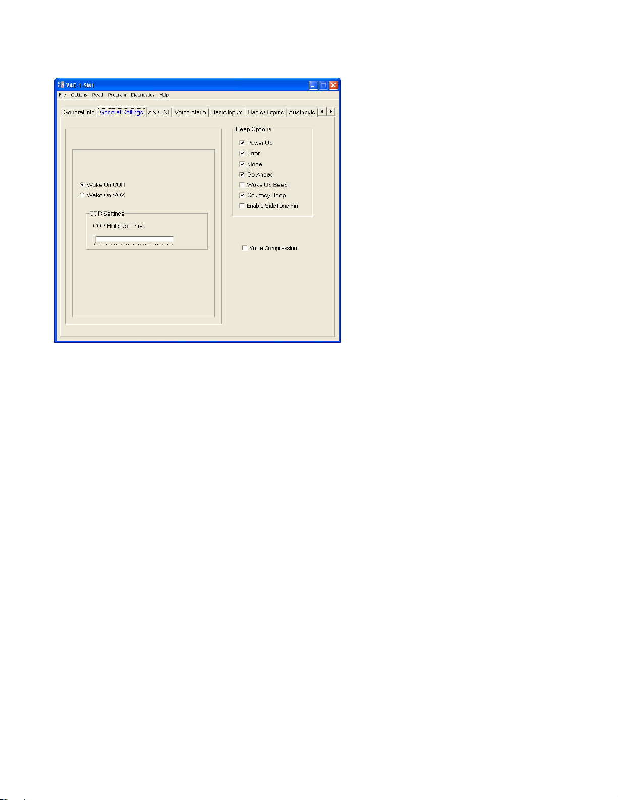
Wake on COR/Wake on VOX: Select the appropriate method that the unit should use to come out of power save.
COR Hold-Up Time This is the amount of time after loss of COR/VOX that the unit considers COR/VOX dropped.
VOX Settings > Sensitivity: This is a threshold detection based on the energy level in the audio.
VOX Settings > Attack Time: This sets the minimum time before the unit will detect VOX based on the sensitivity
setting.
VOX Settings > Decay Time: This sets the time before the unit will drop the VOX detection. Be certain to set this
long enough so that you do not have drop outs between words or on brief pauses.
Beep Options > Power Up: Enables a short beep sequence that takes place immediately after po wer-up.
Beep Options > Error: This beep may be triggered by any input event if programmed to do so. For example, if a
long press on the Mode Input is not assigned to a function, it may be configured to generate the error beep.
Beep Options > Mode: This is used to indicate to the user when the mode has been enabled/disabled (i.e..
Beep Options > Go Ahead: This is a local beep out the speaker to indicate to the user that ANI has been sent
and it is okay to talk.
Beep Options > Wake Up Beep: Enables a short beep to be sent over the air immediately after PTT is pressed.
Enabling this beep is recommended when the 'Wake on VOX' feature is used.
Beep Options > Courtesy Beep: If selected, once the unit is done retran smitting the recorded audio it will
generate a courtesy tone to let others know it is done retransmitting.
Beep Options > Enable Side Tone Pin: Future Use.
Voice Compression: If left unchecked the VAE-1 can store up to a 3-minute voice message. If check the VAE-1
can store up to a 2.25 minute voice message, but with a higher level of audio quality.
5
Page 6
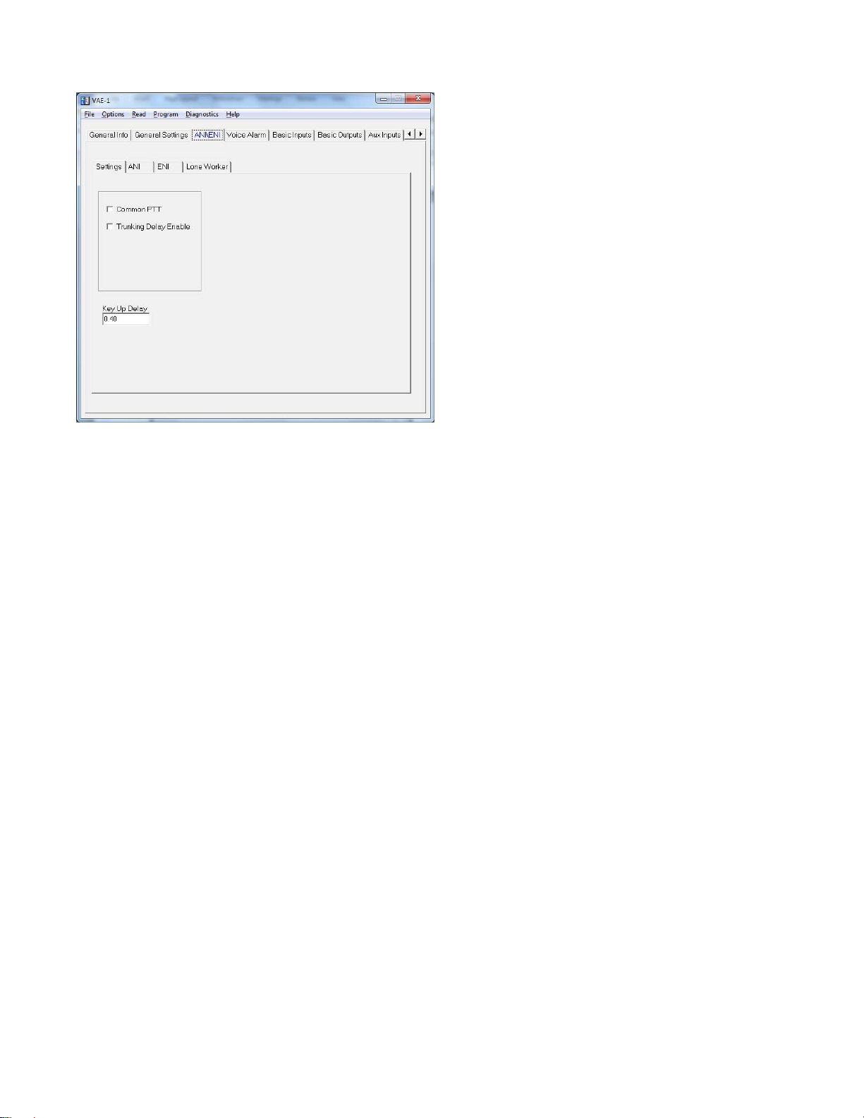
Common PTT: Check this box.
Trunking Delay Enable: Check this box if using a trunking system. This will cause the unit to hold off transmitting
the ANI until it has received a channel acquisition acknowledgement from the radio.
Key-Up Delay: This sets the amount of time the unit waits after keying the radio before it transmitting the ANI.
6
Page 7
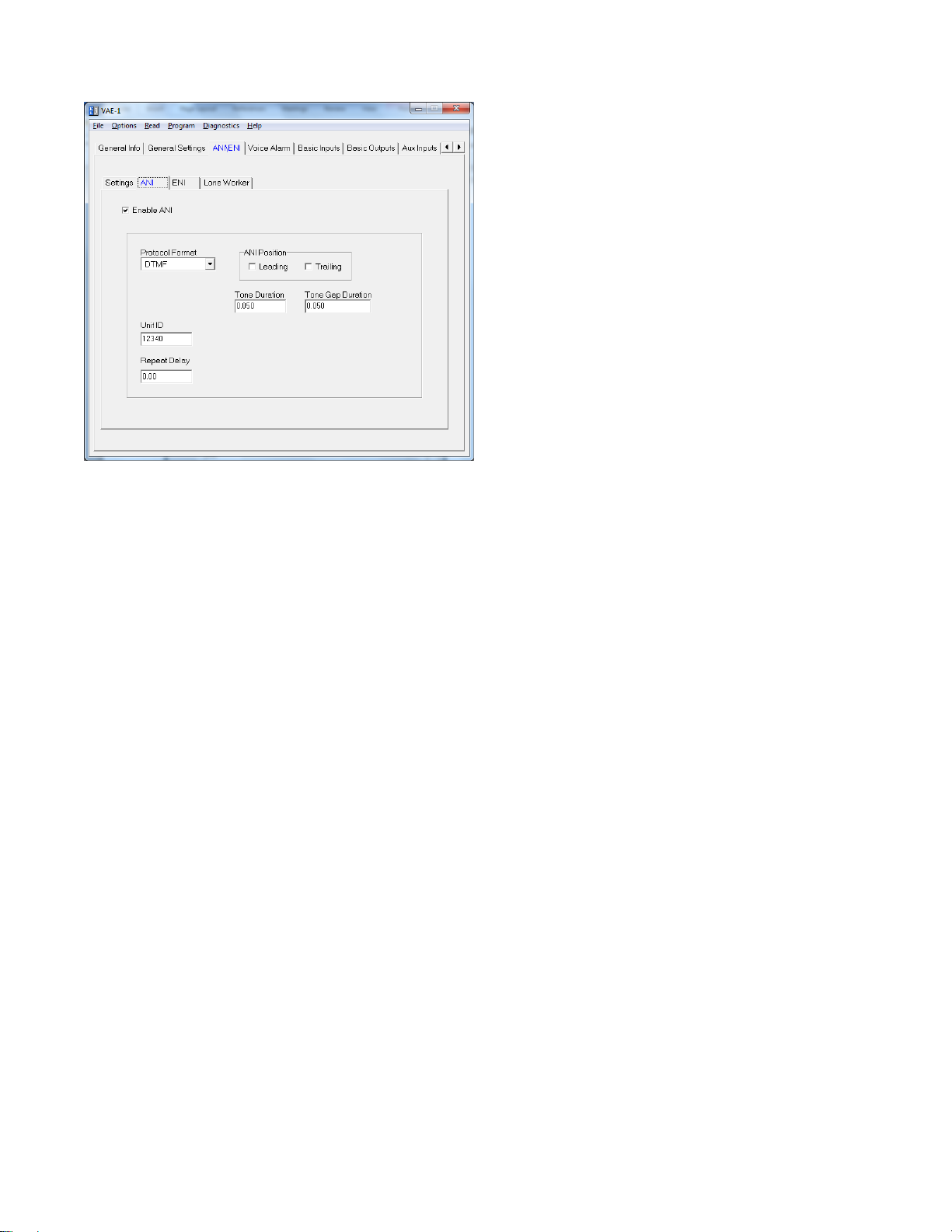
Protocol Format: Select the desired signaling format in which the ANI and ENI will be transmitted.
ANI Position: This can be set for the beginning of transmission (leading), end of transmission (trailing) or both.
Tone Duration: This field only applies to DTMF and 5-Tone formats and sets the length of each tone.
Tone Gap Duration: This field only applies to DTMF and sets the length of the gap between tones.
Fleet ID: This field only applies to FleetSync and sets the Fleet ID of the unit.
Unit ID: This sets the ANI of the unit.
Message: This field only applies to G-Star.
Status: This field only applies to G-Star.
Repeat Delay: This sets the time after sending an ANI that the unit will wait before sending another ANI.
7
Page 8
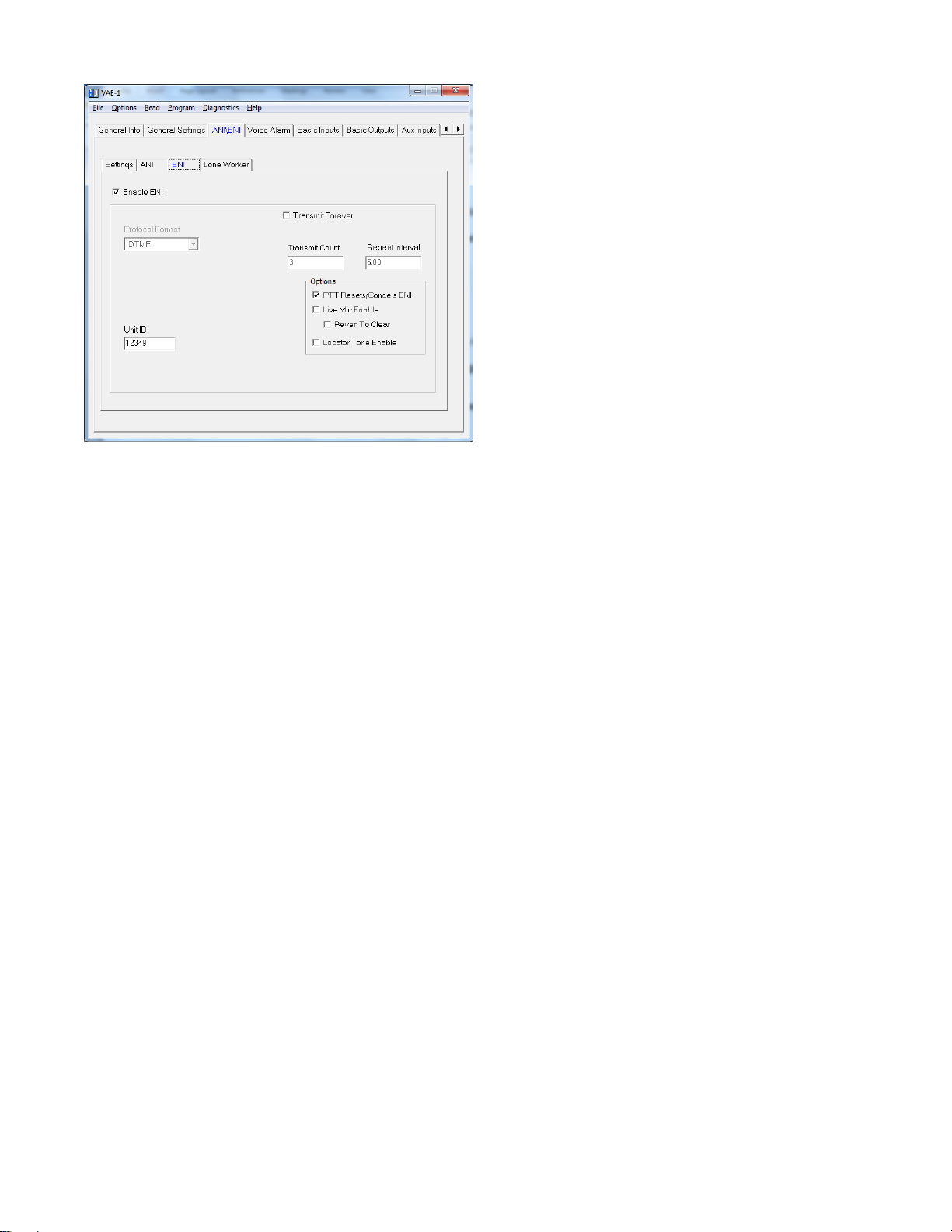
Protocol Format: This displays the format selected on the ANI tab.
Fleet ID: This field only applies to FleetSync and sets the Fleet ID for the ENI.
Unit ID: This sets the Emergency ANI of the unit.
Message: This field only applies to G-Star.
Status: This field only applies to G-Star.
Transmit Forever: If selected the ENI will transmit continuously at the repeat interval until canceled.
Transmit Count: This sets the number of times the ENI will be sent.
Repeat Interval: This sets the time between ENI transmissions.
PTT Resets/Cancels ENI: If selected, pressing the PTT button will either reset the Lone Worker’s Transmit Delay
time or cancel the transmission of the ENI.
Live Mic Enable: If selected the unit will enable the mic of the radio to transmit mic audio to the dispatcher.
Revert to Clear: Currently not used.
Locator Tone Enable: If selected the unit will emit tones out the radio’s speaker after an Emergency ANI is sent.
8
Page 9
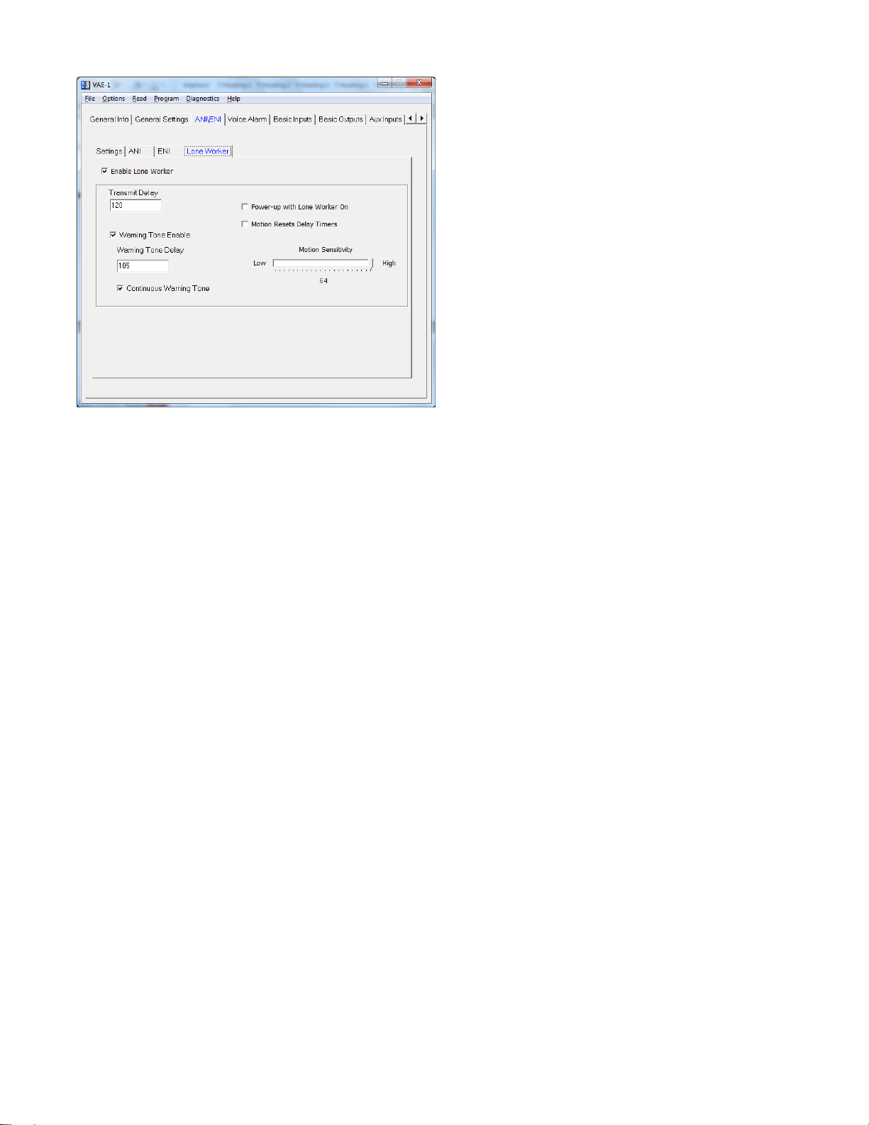
Transmit Delay: In Lone Worker mode, if the user does not interact with the radio before this amount of time
passes, the ENI sequence will be transmitted. This time is in seconds.
Warning Tone Enable: This will generate a tone sequence to alert the user the ENI is about to be transmitted.
Warning Tone Delay: In Lone Worker mode, if the user does not interact with the radio before this amount of
time passes, the emergency warning tone will be sounded. This amount of time must be less than that of the
Transmit Delay for the warning tone to be sounded. Also, the Warning Tone Enable box must be checked for the
tone to be sounded. For example, based on the screen shown above after 105 seconds of no activity the unit will
generate warning tones. The user then has 15 seconds to interact with the radio to keep the Transmit Delay time
of 120 seconds expiring and the ENI being transmitted.
Continuous Warning Enable: This will generate a constant tone to alert the user the ENI is about to be
transmitted.
Power-up with Lone Worker on: If checked the unit will be in Lone Worker mode when the radio is turned on.
This eliminates the need for the user to use the mode input to turn the Lone Worker mode on.
Motion Resets Delay Timers: The unit can then use the accelerometer to detect motion based on the Motion
Sensitivity setting to determine if the user is in distress in addition to requiring interaction with the radio.
Motion Sensitivity: This sets a level of motion required to reset the Transmit Delay timer. Some work
environments may have an inherent level of motion that would be detected by lower settings of the accelerometer,
so a higher level of sensitivity might be needed. Midian recommends experimenting to determine the best
sensitivity setting for the work environment.
9
Page 10

Transmit Frequency: When the emergency input is grounded the unit sends an Emergency ANI either once or
multiple times. This field tells the unit to send the voice alarm with the emergency ANI only on the first Emergency
ANI or on all Emergency ANI’s.
Require PTT to Record: Most radios will only pass audio to the option board when PTT is pressed. If this is the
case this box must be checked. In this mode a button is used to put the unit in record mode and then the PTT is
pressed to pass audio to the unit. The unit keeps the audio from being transmitted in record mode, but only if the
PTT path is broken.
Auto Review: After message recording is completed the unit will replay the message over the speaker to confirm
the message.
Save Message When Powered Off: This will keep the last recorded message in memory when power is cycled.
Auto Record: If checked the unit will start to record immediately upon power up. If the Require PTT to Record
box is checked it will wait for the PTT.
10
Page 11

PTT > Active Polarity: This sets whether the unit looks for an active low or active high to start a recording.
PTT > Debounce: If checked the unit will require a continuous active state for 30 msec before accepting the PTT.
Mode > Type: Select whether the switch is Momentary or Latched.
Mode > Active Polarity: Select the active polarity of the mode switch. In this case it should be Low.
Mode > Debounce: If checked the unit will require a continuous active state for 30 msec before accepting the
mode change.
The remaining fields set how the switch is used (short press, long press or double press) and for which function
(record start, record stop/play, record start/stop, Lone Worker enable or Lon e Worker Reset).
11
Page 12

COR > Active Polarity: This sets whether the unit looks for an active low or active high to start recording the
received audio. For these radios the polarity should be set to high.
COR > Debounce: If checked the unit will require a continuous active state for 30 msec before accepting the
COR.
PTT > Active Polarity: This sets the polarity necessary for the unit’s PTT output to key the radio.
12
Page 13

Audio Enable > Active Polarity: This sets the polarity necessary for the unit to enable the speaker of the radio to
pass beeps.
Emergency > Active Polarity: This sets whether the unit looks for an active low or active high to trigger an
emergency ANI.
Emergency > Debounce: If checked the unit will require a continuous active state for 30 msec before accepting
the Emergency input activation.
Off Function: This can be set for Emergency Cancel, Lone Worker Enable or Lone Worker Reset.
On Function: This can be set for Emergency On, Lone Worker Enable or Lone Worker Reset.
13
Page 14

Trunking Delay Input > Active Polarity: This sets whether the unit needs an active low or active high indication
from the radio to indicate a trunked channel has been established.
14
Page 15

Tones > Beep Volume: Adjust the slider for the desired beep volume. This level is expressed as a percentage of
max voice audio level.
Tones > Over-The-Air-Signal Modulation: Adjust the slider for the desired modulation of the Emergency ANI.
This level is expressed as a percentage of max voice audio level. Midian recommends using 67%.
Playback > Playback Level: This controls the audio level when a stored voice message is played back on the
radio speaker. If voice playback is too low or too loud, adjust this level accordingly.
Playback > Transmit Level: This controls the audio level when a stored voice message is retransmitted over the
air. If the transmit level is too low or too loud, adjust this level accordingly.
15
Page 16

AUDIO LEVELS ALIGNMENT
This section describes how to determine and set the audio levels.
Audio Levels Overview:
To ensure the best audio quality, the unit must be configured to match the audio levels used by the radio. The unit
uses programmable gain amplifiers to accomplish this. Determining the gain settings for these amplifiers is an
involved process, so Midian simplified this process by developing an algorithm that requires the technician to
make only four voltage measurements. From these four measurements, all of the many internal settings are
determined.
Still, getting the best audio quality will likely require a bit of trial and error. The unit only has control of audio
voltage levels, not input and output impedances. These impedances can dramatically influence the levels.
The Four Voltage Measurements:
An oscilloscope and a communications test set/service monitor are required for the measurements. It is
recommended that the measurements be recorded in units of mV peak-to-peak. Each measurement must be
taken with system modulation at either 60% or 100%, but Midian recommends using 60%
A method for controlling transmit modulation is required for accurate measurements in the TX mode. A small
speaker held in place near the microphone by a rubber band can serve this purpose in most cases. Use a sinewave generator to inject a 1000 Hz tone into the speaker. Adjust the output of the sine wave generator so that the
transmitter produces 60% of rated modulation while PTT is pressed. Note that if the audio source (such as a
speaker) is moved even slightly, the TX modulation may change significantly. Care must be taken to avoid
changing the TX modulation while taking the measurements.
The first two measurements must be taken using a radio that has not been modified. The 2
require that the unit is installed and power is applied to the radio/unit. These measurements must be taken within
15 seconds of powering on the unit. This is because the unit may enter power saving mode after that time.
Measurements made while the unit is in power saving mode will not be valid. The unit ships with the power save
feature enabled by default. The power save feature can be disabled via the programming software so that it will
not interfere with taking measurements, if desired. Please note that the levels provided to the option board are
different between narrow band and wide band.
1. TX Input: This procedure is to determine the audio level that the unit will see at the TX audio pickup point
after it is installed. The unit must be installed and powered-on while making this measurement. Use the TX
Alignment Set-Up procedure and measure the audio level at TP1 on the unit.
2. RX Input: This procedure is to determine the audio level that the unit will see at the RX audio pickup point
after it is installed. The unit must be installed and powered-on while making this measurement. Use the TX
Alignment Set-Up procedure and measure the audio level at TP2 on the unit.
3. In the programming software under audio levels set the TX In to the same level as measured in step 1 and for
a preliminary adjustment set the TX Out for the same level. Set the RX In to the same level as measured in
step 2 and for a preliminary adjustment set the RX Out for the same level. Program the unit.
4. RX Output: This procedure is to determine the audio level that would normally appear at the RX audio
insertion point in an unmodified radio. Using the same RX Alignment Set-Up procedure verify the audio level
at the speaker is still at the same level measured initially in the RX Alignment Set-Up procedure. If not adjust
the RX Out level accordingly.
5. TX Output: The goal of this procedure is to determine the audio level that would normally appear at the TX
audio insertion point in an unmodified radio. Using the same TX Alignment Set-Up procedure verify the
modulation is still at 60%, if not adjust the TX Out level accordingly.
nd
two measurements
16
Page 17

Programming the Audio Levels:
After determining the audio levels at the audio hookup points, it will be necessary to program the unit to match
these levels. In the programming software, there is a slider control on the Audio Levels Screen for each of the of
four audio hookup points. Locate the column that corresponds to the modulation and units of measurement for
each of the audio hookup points. Adjust the slider bar such that the value appearing in the appropriate column
matches what was measured as closely as possible. Midian recommends the following values based on 60%
modulation:
Radio Model RX In TX In RX Out TX Out
VX-350 240 114 240 48
VX-410, VX-420 282 198 414 156
VX-450, VX-460 390 192 354 546
VX-600, VX-900 348 90 444 66
VX-820 324 66 540 48
VX-920
VX-2100, VX-2200 402 96 402 96
VX-4100, VX-4200 354 210 324 168
VX-4500, VX-4600 390 192 354 546
VX-5500 234 54 318 54
VX-6000
17
Page 18

HARDWARE INSTALLATION
Be certain to follow standard anti-static procedures when handling any of Midian’s products.
VX-350:
Remove the battery, exposing the option board cover and remove the cover. Plug the unit onto the options
connector. Replace the option board cover and battery. Firmware version 1.0 or higher should be used.
VX-410 & VX-420:
Remove the battery, exposing the option board cover and remove the cover. Remove the dummy board from the
radio and replace with the unit. Replace the option board cover and battery. Firmware version 1.04 or higher
should be used.
VX-450 & VX-460:
Remove the battery, exposing the option board cover and remove the cover. Plug the unit onto the options
connector. Replace the option board cover and battery. Firmware version 1.10 or higher should be used.
VX-600 & VX-900:
Remove the battery, exposing the option board cover and remove the cover. Remove the dummy board from the
radio and replace with the unit. Replace the option board cover and battery. Firmware version 1.22 or higher
should be used.
VX-800:
Remove the battery, exposing the option board cover and remove the cover. Remove the dummy board from the
radio and replace with the unit. Replace the option board cover and battery. Firmware version 1.28 or higher
should be used.
VX-820 & VX-920:
Remove the battery, exposing the option board cover and remove the cover. Plug the unit onto the options
connector. Replace the option board cover and battery. Firmware version 1.19 or higher should be used.
VX-2100 & VX-2200:
Remove the cover of the radio exposing the options connector. Plug the unit onto the Options Connector.
Replace the cover of the radio. Firmware version 1.00 or higher should be used. Note: Some versions of this
radio may have a large diode (D1002) installed under the options connector that can cause a short on the unit. If
this diode is present protect the option board using electrical or kapton tape.
VX-4100 & VX-4200:
Remove the cover of the radio exposing the options connector. Plug the unit onto the Options Connector.
Replace the cover of the radio. Firmware version 1.25 or higher should be used.
VX-4500 & VX-4600:
Remove the cover of the radio exposing the options connector. Plug the unit onto the Options Connector.
Replace the cover of the radio. Firmware version 1.10 or higher should be used.
18
Page 19

VX-4000, VX-5500 & VX-6000:
Remove the cover of the radio exposing the options connector. Plug the FIF-7A (from Vertex) onto the options
connector per Vertex’s instructions. Then plug the unit onto the FIF-7A. Replace the cover of the radio.
Firmware version 2.02 or higher is required in the VX-4000. Firmware version 0324 or higher should be used in
the VX-5500. Firmware version 4.02 or higher should be used in the VX-6000.
19
Page 20

RADIO PROGRAMMING
VX-350:
For the VX-350 radio programming software CE-86 v1.01 or higher must be used.
Read the radio with the option board installed. Select “Common” from the menu and then “Option”. The “Option
Unit” should be read as “FVP-35”.
Under the “Common” heading select “Key Function” to set which key will control the Emergency ANI or Lone
Worker on/off. Program the desired button to “Option Switch” or “Option Switch 2”.
Download the program to the radio.
VX-410 & VX-420:
For the VX-410 & VX-420 radio programming software CE-64 v1.00 or higher must be used.
Read the radio with the option board installed. Select “Common” from the menu and then “Option”. Set the
“Option Board” to “Encryption (Hi Level)”.
Under the “Common” heading select “Key Function” to set which key will control the Emergency ANI or Lone
Worker on/off. Set the “Side 1” or “Side 2” Key to “ACC 1”. Press or Press & Hold may be used. The assigned
button will then control the Emergency ANI. On full keypad versions the A, B, C, or D button may be used.
In the main screen, in the “ENCR” column, every channel must have the flag checked. NOTE: This does not
provide encryption on a per channel basis. On this screen, the “SQ” column must have a figure greater than “0”.
Download the program to the radio.
VX-450 & VX-460:
For the VX-450 & VX-460 radio programming software CE-115 v1.01 or higher must be used.
Read the radio with the option board installed. Select “Common” from the menu and then “Option”. The “Option
Unit” should be read as “FVP-35”.
Under the “Common” heading select “Key Function” to set which key will control the Emergency ANI or Lone
Worker on/off. Set the mode select button to “Option Switch 1”.
Download the program to the radio.
VX-600 & VX-900:
For the VX-600 & VX-900 radio programming software CE-39 v1.04 or higher must be used.
Read the radio with the option board installed. Select “Common” from the menu and then “Miscellaneous”. Set
the “Encryption Type” to “Hi Level”. This will also change the “Encryption Device” setting under “Common” >
“Option” to “Yes”.
Under the “Common” heading select “Key Function” to set which key will control the Emergency ANI or Lone
Worker on/off. Set the “TOP SEL Key” (top orange button), “SIDE SEL Key” (top side button), or the A, B, C, or D
(keypad models only) button to “ACC1”. The assigned button will then control the Emergency ANI.
In the main screen, in the “ENCR” column, every channel must have the flag checked. NOTE: This does not
provide encryption on a per channel basis.
Download the program to the radio.
20
Page 21

VX-800:
For the VX-800 radio programming software CE-31 v1.20 or higher (DOS) or v1.05 (Windows) must be used.
Read the radio with the option board installed. Select “Common” from the menu and then “Miscellaneous”. Set
the “Encryption Type” to “Hi Level”. This will also change the “Encryption Device” setting under “Common” >
“Option” to “Yes”.
Under the “Common” heading select “Key Function” to set which key will control the Emergency ANI or Lone
Worker on/off. Set the “SEL1 Key” (top orange button), “SEL2 Key” (top gray button), or the A, B, C, or D (keypad
models only) button to “ACC1”. The assigned button will then control the Emergency ANI.
In the main screen, in the “ENCR” column, every channel must have the flag checked. NOTE: This does not
provide encryption on a per channel basis.
Download the program to the radio.
VX-820 & VX-920:
For the VX-820/920 radio programming software CE-59 v2.10 or higher must be used.
Read the radio with the option board installed. Select “Common” from the menu and then “Option”. The “Option
Unit” should be read as “FVP-35”.
Under the “Common” heading select “Key Function” to set which key will control the Emergency ANI or Lone
Worker on/off. Program the desired button to “Option SW1” or “Option SW2”. Option SW1 is momentary and
Option SW2 is latched.
Download the program to the radio.
VX-2100 & VX-2200:
For the VX-2100 & VX-2200 radio programming software CE-82 v1.04 or higher must be used.
Read the radio with the option board installed. Under the “Common” heading select “Key Function” to set which
key will control the Emergency ANI or Lone Worker on/off. Set the “P1-P4 Short Press” button to “Option SW”.
Download the program to the radio.
VX-4100 & VX-4200:
For the VX-4100 & VX-4200 radio programming software CE-59 v1.01 or higher must be used.
Read the radio with the option board installed. Select “Common” from the menu and then “Option”. The “Option
Unit” should be read as “FVP-35”.
Under the “Common” heading select “Key Function” to set which key will control the Emergency ANI or Lone
Worker on/off. Set the “P1-P4” or “A” button to “Option Switch 1”.
Download the program to the radio.
NOTE: The VX-4100 & VX-4200 currently does not provide the unit with a COR Input, therefore program the unit
for Wake on VOX feature should be used rather than Wake on COR.
21
Page 22

VX-4500 & VX-4600:
For the VX-4500 & VX-4600 radio programming software CE-115 v1.01 or higher must be used.
Read the radio with the option board installed. Select “Common” from the menu and then “Option”. The “Option
Unit” should be read as “FVP-35”.
Under the “Common” heading select “Key Function” to set which key will control the Emergency ANI or Lone
Worker on/off. Set the “P1-P4” or “A” button to “Option Switch 1”.
Download the program to the radio.
VX-4000, VX-5500 & VX-6000:
For the VX-4000 radio programming software CE-35 v2.0.2.0 or higher or CE-49 v3.3.0.0 or higher must be used.
For the VX-5500/VX-6000 radio programming software CE-49 v3.3.0.0 or higher must be used.
Read the radio with the option board installed. Select “Common” from the menu and then “Option”. Set the
“Option Unit” to “FVP-35 (Hi Level Encr)”. This will also change the “Encryption Type” setting under “Common” >
“Miscellaneous” to “Hi Level”.
Under the “Common” heading select “Key Function” to set which key will control the Emergency ANI or Lone
Worker on/off. Set the PF1-PF5 (long or short) button to “Hi-Level Enc SW”.
In the main screen, in the “ENCR” column, every channel must have the flag checked. NOTE: This does not
provide encryption on a per channel basis.
Download the program to the radio.
22
Page 23

OPERATION
ANI Encode: When the PTT button is pressed, the unit will assert the PTT Output and send the programmed
ANI tones out the TX Tone Output.
ENI Encode: When the Emergency button is pressed, the unit will assert the PTT Output and send the
programmed Emergency ANI tones out the TX Tone Output. Note: On the portable radios the emergency from
the external mic is not supported.
Lone Worker Enable: The Lone Worker feature can be enabled upon power up or using the Mode Input or
Emergency Input.
Lone Worker Reset: If the Lone Worker feature is being used, pressing the PTT or pressing the button assigned
to Lone Worker Reset will reset the Transmit Delay timer. If the Warning Tone Delay time expires the unit will
generate warning tones to indicate to the user that the Lone Worker feature is about to send an ENI if the unit
does not see PTT or Lone Worker Reset activity. If the Transmit Delay time then expires the unit will send the
ENI.
Message Recording on Power Up: If the Auto Record feature is enabled the unit will record a voice message
immediately upon power up. If the radio requires PTT to pass voice to the option board and the Require PTT to
Record box is checked, the unit will wait to record until the PTT is pressed.
Message Recording with Mode Button: Using the button(s) set for controlling record start and stop, press the
button in the manner programmed in Mode Input to start recording. If the radio requires PTT to pass voice to the
option board and the Require PTT to Record box is checked, the unit will wait to record until the PTT is pressed.
When recording is completed, press the button in the manner programmed in Mode Input to stop recording. When
the recording is stopped the unit will play back the recorded message if the Auto Review box is checked.
23
Page 24

TECHNICAL NOTES
Radio Compatibility: Midian has taken the utmost care to ensure the option board integrates into the radio with
minimal impact to the features of the radio. However, some features may not be available in the radio when an
option board is used. If a feature is not available, please contact Midian to see if the feature can be added.
MIDIAN CONTACT INFORMATION
MIDIAN ELECTRONICS, INC.
2302 East 22
nd
Street
Tucson, Arizona 85713 USA
Toll-Free: 1-800-MIDIANS
Main: 520-884-7981
E-mail: sales@midians.com
Web: www.midians.com
24
Page 25

1
1
2
2
3
3
4
4
5
5
6
6
D D
C C
B B
A A
TP15
N/C
P1-2
P1-28
47K
R6
N/C
P1-11
TP11
ROW 4
P1-31
P4:4
RX OUT
P1-14
TP7
P1-34
AUDIO ENABLE
P1-17
P4:3
TP3
R0W 1
P1-37
N/C
P1-5
TX IN
P1-20
COR IN
PAD6
32kHz
Y1
4001
Q4
MODE IN
P1-8
COL 4
P1-23
TP16
4001
Q6
161342
11
9
4
3
37
8
47
28
24
27
20
18
36
43
46
48
45
41 6
44
1
2
38
40
39
34
21
22
7
35
17
19
29
25
23
26
1210
5
15
14
33
32
30
31
49
U1
560p
C48
P4:2
*
IN1
1
ENA
3
GND
2
LVF
4
OUT
5
VR2
GND
P1-39
P1-26
TP12
N/C
P1-12
TP8
COL 1
P1-29
P1-32
PTT OUT
P1-15
P3:5
P4:1
TP4
ROW 2
P1-35
PTT IN
P1-3
TX OUT
P1-18
TP17
P1-38
PROG OUT
PAD4
N/C
P1-6
748
2 5
1
6
3
U4
N/C
P1-21
TP13
AUDIO SWITCH
P1-9
P1-24
PROG IN
PAD3
PTT IN
PAD2
+3.5V
P1-40
P3:2
P3:1
COL 2
P1-27
RX IN
P1-16
TP5
COR IN
P1-10
N/C
P1-13
TP18
P1-30
TP1
PTT OUT
PAD1
IN1
1
ENA
3
GND
2
LVF
4
OUT
5
VR1
TP14
ROW 3
P1-33
GND
P1-1
P4:6
+VB
P1-4
N/C
P1-19
TP10
P1-36
N/C
P1-7
P1-22
3
1
2
4
5
6
U5
*
IN1
1
ENA
3
GND
2
LVF
4
OUT
5
VR3
TP6
P3:3
16
15
33
3
11
12
20
46
21
2
39
40
41
42
3231131045
17
43
30
29
26
27
28
51434
44
U3
COL 3
P1-25
P4:5
TP2
P3:4
VAN
VAN
VAN
VAN
VAN
IN SYSTEM
SERIAL PROGR.
(SOURCE)
(TX RAIL)
NOTES:
* = NOT INSTALLED
47K
R7
4.7K
R8
*
R10
*
R9
*
R11
*
R12
*
R19
*
R20
*
R21
*
R23
*
R22
3.3K
R24
75K
R26
1K
R25
*
R39
*
R40
*
R41
100K
R15
0R
R35
*
R16
*R18
*
R13
*
R28
560p
C2
.1u
C3
.1u
C42
*
C12
*
C14
*
C11
*
C15
*
C17
*
C16
.01u
C21
*
C25
*C30
*
C29
*
C28
*C36
*
C33
2.2u
C40
.1u
C41
.1u
C23
.1u
C22
560p
C4
10u
+
C5
*
C8
*
C7
.1u
C6
560p
C1
*
C10
.01u
C9
*
C18
*
C44
*
C19*C20
*
C26
*
C27
*
C31*C32
100p
C39
12p
C38
*
C45
.1u
C13
+VIN
+3.3V
+3.3VA
+3.3VDD
+VIN
+3.3V
+3.3V
+3.3V
+3.3V
+3.3V
+3.3V
+3.3VA
+3.3VDD
+3.3V
+3.3V
220p
C24
SB1D1
SB1
D4
SB1
D3
SB1
D2
*
R17
*
R34
*
R36
SB1D5
EM
PAD7
47K
R42
CS
1
SO
2
SI
5
SCK
6
VCC
8
HOLD
7
WP
3
GND
4
-
U6
CS
7
SO
12
SI
13
SCK
14
DVDD
1
INT2
9
INT1/DRDY
8
GND
2
-
AVDD
6
GND
5
IADDR0
4
3
10
11
U8
VOICE OPTION
ACCELEROMETER OPTION
.1µ
C49
+3.3V
.1u
C46
+3.3V
+3.3V
47K
R31
+3.3V
4.7K
R30
-
+
1
3
4
52
U9
*
+3.3V
-
+
1
3
4
52
U10
*
-
+
1
3
4
52
U11
*
-
+
1
3
4
52
U7
*
+3.3V
+3.3V
.1u
C34
0R
R44
*
R43
*
R46
0R
R45
CP
CJS
2007-12-01
DML
2013-02-04
D-3
1 of 1
7506
MIDIAN ELECTRONICS, INC.
DATE:
DESIGN:
DWN BY:
REV:
APPR
COPYRIGHT ©
REV
SHEET
PROJECT NUMBER
DOCUMENT NAME
SCHEMATIC
2013
VAE-1-VX1
COD1
COPAD6
PIPAD601
PIR4501
PIR4502
COR45
PIC201
COC2
PIC202
COPAD1
PIPAD101
COPAD2
PIPAD201
PIC101
PIC102
COP1:9
PIP109
COR43
PIR4302
COR34
PIR3402
COR35
PIR3502
COC4
PID101 PID102
COD4
COD3
COC3
PIC301 PIC302
COC42
PIC4201 PIC4202
PIR4601
COC1
PIR4401
PIC401
PIC501
PIC402
PIC502
COP1:23
PIP1023
COP1:25
PIP1025
COP1:27
PIP1027
COP1:29
PIP1029
COP1:31
PIP1031
COP1:33
PIP1033
COP1:35
PIP1035
COP1:37
PIP1037
COP1:8
PIP108
COP1:10
PIP1010
COP1:20
PIP1020
COP1:16
PIP1016
COP1:15
PIP1015
COP1:3
PIP103
COP1:2
PIP102
COP1:5
PIP105
COP1:6
PIP106
COP1:7
PIP107
COP1:11
COP1:12
COP1:13
COP1:19
COP1:21
PIP1011
PIP1012
PIP1013
PIP1019
PIP1021
PIR4301
COP1:4
PIR3401
PIP104
COP1:40
PIP1040
COP1:1
COP1:39
PIP101
PIP1039
PIR3501
PIP1022
PIP1024
PIP1026
PIP1028
PIP1030
PIP1032
PIP1034
PIP1036
PIP1038
PID401PID402
PID301PID302
COTP1
PITP101
COTP2
PITP201
COR46
PIR4602
COR44
PIR4402
PITP1001
COTP17
PITP1701
COC5
PIR1501
COR15
PIR1502
COP1:22
COP1:24
COP1:26
COP1:28
COP1:30
COP1:32
COP1:34
COP1:36
COP1:38
PIR701 PIR702
PIR601 PIR602
COVR1
PIVR101
PIVR103
COVR2
PIVR201
PIVR203
COTP10
COVR3
PIVR301
PIVR303
COR7
COR6
COD2
PID201PID202
PIVR104
PIVR102
PIVR204
PIVR202
PIVR304
PIVR302
PIC4801
COC48
PIC4802
COR39
PIR3901 PIR3902
PIVR105
COR40
PIR4001 PIR4002
PIVR205
COR41
PIR4101 PIR4102
PIVR305
PIQ60D
COQ6
PIQ60S
COC9
COTP5
PIC601
PIC3401
COC6
PIC602
PIC3402
COTP16
PITP1601
PIC701
COC7
PIC702
COTP14
PITP1401
PIC801
COC8
PIC802
COR36
PIQ60G
PIC901
PIC902
PITP501
COTP13
PITP1301
COC34
PIC1001
PIC1002
PIR1301
PIR1302
PIR1601
PIR1602
PIR3601PIR3602
PITP601
PIC1201 PIC1202
COC10
COR13
COC15
PIC1501 PIC1502
COC16
PIC1601 PIC1602
COR16
COR8
PIR801 PIR802
COTP6
COC12
PIR901 PIR902
PIU1101
PIU1103
COR9
COR11
PIR1101 PIR1102
COC14
PIC1401 PIC1402
COC17
PIC1701 PIC1702
COR18
PIR1801 PIR1802
PIU1105
COU11
PIU1102
COD5
COPAD7
PIPAD701
COC11
PIC1101 PIC1102
COR10
PIR1001 PIR1002
PIU905
PIU901
COU9
PIU903
PIU902
PIR1201 PIR1202
PIU1001
PIU1003
PIU1104
COTP11
PID501PID502
PIU904
COR12
PIU1005
COU10
PIU1002
COR19
PIR1901 PIR1902
COR21
PIR2101 PIR2102
COC18
PITP1101
PIC1301
COC13
PIC1302
COTP15
PIU503
PIU501
PIU1004
COR20
PIR2001 PIR2002
PIU701
COU7
PIU703
PIC1801
PIC1802
COC41
PIC4101
PIC4102
PIU1011
PIU1010
PIU109
PIU108
PIU105
PIU1023
PIU1013
PIU1037
PIU1028
COU1
PIU1024
PIU1043
PIU1036
PIU1046
PIU1018
PIU1049
PIU1025
PIU1047
PIU1020
PIU1045
PIU1041
PIU1044
PIU505 PIU506
COU5
PIU101 PIU102
PITP1501
PIU504
PIC4401
PIC4402
PIU502
PIR1701 PIR1702
COTP8
COC40
PIC4001
PIU1016
PIU1042
PIU1048
COC44
COR17
PIC4002
PIU1038PIU1039PIU1040
PIU402
PITP801
PIU705
PIU704
PIU702
COtb0sch1
PIR3102
COR31
PIR3101
PIU1031
PIU1012
PIU1030
PIU1032
PIU1033
PIU104
PIU103
PIU1014
PIU1015
PIU1026PIU1027
COP3:1
COP3:2
COP3:3
PIP301
PIP302
PIU1029
PIU1019
PIP303
PIY102
COY1
PIY101
COTP12
PITP1201
PIC4501
PIC4502
COC25
PIC2501
PIU404
PIU407PIU408
PIU403
PIU406
COTP18
COR28
PIR2801 PIR2802
COC45
PIC2502
COU4
PIU405
PIU1017
PIU1035
PIU107
PIU1022
PIU1021
PIU1034
PIU106
PIU401
PITP1801
PIC1901
COC19
PIC1902
PIR4202
COR42
PIR4201
COP3:4
COP3:5
PIP305
PIP304
PIC3901
COC39
PIC3902
PIC3801
COC38
PIC3802
PIU3016
PIU3015
PIU303
PIU3012
PIU3011
PIU3020
PIU3046
COTP7
COR24
PIR2401
PIR2402
PIC2101
PIC2102
PIC2001
COC20
PIC2002
COU6
PIU601
COU8
PIU305
PIU3014
PIU3044
COU3
PIU3013
PIU3021
PIU3031PIU3032
PIU3010
PIU602
PIU605
PIU606
PIU8012
PIU8013
PIU8014
PIU808
PIU809
PIU3033 PIU3034
PITP701
COC21
COR23
PIR2301
PIR2302
PIR2201
COR22
PIR2202
COC46
PIC4601 PIC4602
PIU608
PIU607
PIU603
PIU604
PIU801
PIC4901
PIU806PIU807
PIU804
PIC4902
PIU803
PIU8010
PIU8011
PIU805
PIU802
COC36
PIC3601 PIC3602
COC33
PIC3301 PIC3302
PIU3030
PIU3029
PIU3026
PIU3027
PIU3028
PIU3043
PIU3017
PIU3039
PIU3040
PIU3041
PIU3042
PIU302
PIU3045
COC49
PIC3101
COC31
PIC3102
COC30
PIC3001 PIC3002
COC29
PIC2901 PIC2902
COC28
PIC2801 PIC2802
COC27
PIC2701 PIC2702
COC26
PIC2601 PIC2602
PIR3002
COR30
PIR3001
PIC3201
COC32
PIC3202
PIP404
COP4:4
PIP403
COP4:3
PIP402
COP4:2
PIP401
COP4:1
PIP405
COP4:5
PIP406
COP4:6
COC23
COR26
PIC2301 PIC2302
PIR2601
PIR2602
COC22
COR25
PIC2201 PIC2202
PIR2501
PIR2502
PIQ40D
PIQ40G
PIQ40S
COTP3
PITP301
COTP4
PITP401
COPAD3
PIPAD301
COPAD4
PIPAD401
COP1:17
PIP1017
COQ4
COP1:18
PIP1018
PIC2401
COC24
PIC2402
COP1:14
PIP1014
Page 26

- This page intentionally left blank -
Page 27

COVO1
COPAD1
PAPAD101
COR36
PAR3602 PAR3601
PAR3001
PAPAD301
PAPAD401
COPAD4
COR22
COR23
COfid1
COR30
PAR3002
COPAD3
COD3
PAD301 PAD302
COC34
PAC3402
PAC3401
COR21
PAR2101
PAR2102
COC18
PAC1802
PAC1801
PAU704
COU7
PAU705
COR20
PAR2001
PAR2002
COR19
PAR1902PAR1901
COTP6
COC12
PAR1701
PATP601
COR9
PAR902
COR17
PAR1702
COC11
PAC1101
PAR2401
COR24
COR10
PAR1001
PAR2402
PAU901
PAC2101
COC21
COU9
PAU902
PAU903
PAC2102
COC20
PAC2002
COU4
PAR2202 PAR2201
PAU406
PAU407
PAU408
COC25
PAVO100
PAfid100
PAQ60D
PAC4801
PAVO101
COQ6
PAQ60G
COR26
COR25
PAR2501 PAR2502
PAPAD601
PAU1104
COU11
PAU1105 PAU1101
COR18
PAU703
PAU702
COC17
PAU701
PAC1502
COC15
PAC1501
PAC1202PAC1201
PAR901
PAC1102
PAR1002
PAU905
PAU904
PAC2001
PAR2301PAR2302
PAC2502PAC2501
COC48
PAQ60S
PAC4802
PAC2301
PAR2602PAR2601
PAC2201
COR45
PAR4502 PAR4501
COPAD6
PAU1103
PAC902
PAU1102
PAC901
PAR1801PAR1802
PAC1701PAC1702
PAC1602
PAR1301
COC16
PAC1601
PAR1302
COR16
PAR1601 PAR1602
PAU1004
COU10
PAU1005 PAU1001
COR12
PAR1202 PAR1201
COC14
COR11
PAR1101 PAR1102
COC19
COTP18
PATP1801
PAC1901 PAC1902
PAU404PAU405
PAU403
PAU402
COU5
PAU504 PAU505 PAU506
PAU401
COC44
PAC4401 PAC4402
PAD202
PAD201
PAC2302
PAC2202
COC9
PAC1001
PAC1002
COR13
PAU1003
PAU1002
PAC1402PAC1401
COC1
PAC101
COD2
PAC102
PAVO10LB
PAP10LB
COD4
PAU601
COC10
PAU602
PAU603
COTP8
PATP801
PAU101
PAU102
PAU103
COU1
PAU104
PAU105
COTP15
PAU106
PAU107
PAU108
PATP1501
PAU109
PAU1010
PAU1011
PAU1012
PAU501PAU502PAU503
PAC4001
COC40
PAC4002
COR46
PAPAD201
COPAD2
PAVO103
PAP103
PAP101
COC23
COC22
PAP104
PAP102
PAVO104
PAVO102
PAD402PAD401
COR8
PAR801
PAR802
PAR4602PAR4601
PAVO1013
PAVO1011
PAVO109
PAVO107
PAVO105
PAP105
COP1
PAP106
PAVO106
PAP1013
PAP1011
PAP109
PAP107
COTP4
PATP401
PAP1014
PAP1012
PAP1010
PAP108
PAVO1014
PAVO1012
PAVO1010
PAVO108
COC24
PAC2402
COR31
PAR3102
PAC4101
PAC4102
COC41
PAVO1041PAVO1042PAVO1043PAVO1044PAVO1045PAVO1046PAVO1047PAVO1048
PAU1040PAU1041PAU1042PAU1043PAU1044PAU1045PAU1046PAU1047PAU1048
PAU1049
PAU1013 PAU1014 PAU1015 PAU1016 PAU1017 PAU1018 PAU1019 PAU1020 PAU1021
PAC3801
COC38
COY1
PAY101
PAC3802
PAVO10S
PAQ40S
COQ4
PAVO10D
PAQ40D
PAVO1017
PAVO1015
PAP1017
PAP1015
COTP3
PATP301
PAP1018
PAP1016
PAVO1018
PAVO1016
PAC2401
PAU608
COU6
PAU607
PAU606
PAU605PAU604
COC2
PAC202
PAVO10G
PAQ40G
PAVO1025
PAVO1023
PAVO1021
PAVO1019
PAP1025
PAP1023
PAP1021
PAP1019
PAP1026
PAP1024
PAP1022
PAP1020
PAVO1026
PAVO1024
PAVO1022
PAVO1020
COD1
PAR3101
COTP11
PAU1037PAU1038
PAU1039
PATP1101
PAU1036
PAU1035
PAVO1049
PAU1034
PAU1033
PAU1032
PAU1031
PAU1030
PAU1029
PAU1028
PAU1027
PAU1026
PAU1025
PAU1022
PAU1023 PAU1024
PAC3902
PAY102
PAC3901
COC42
COTP2
COR6
PAC4202PAC4201
COTP1
PAC201
PAVO1035
PAVO1033
PAVO1031
PAVO1029
PAVO1027
PAP1027
PAP1035
PAP1033
PAP1031
PAP1029
PATP201
PAC301 PAC302
COC3
PAVO1037
PAP1037
COR7
PATP101
PAR701 PAR702
PAVO1039
PAP1039
PAVO10RB
PAR3501
PAP10RB
COTP17
PAR3502
PATP1701
PAC401
PAP1028
PAVO1032
PAVO1030
PAVO1028
PAD101PAD102
PAC4601
PAC4602
PAVO1040
PAVO1038
PAVO1036
PAVO1034
PAU808
COC46
PAU809
PAU8010
PAU8011
PAU8012
PAU8013
PAC402
COR42
PAU807
PAU806
COU8
PAU805
PAU804
PAU803
PAU802
PAU801
PAP1040
PAP1038
PAP1036
PAP1034
PAP1032
PAP1030
PAU8014
COC26
PAC2601 PAC2602
PAU3012
PAU3011 PAU3010
PAU3013
COU3
PAU3014
PAU3015
PAU3016
COTP5
PAU3017
PAU3018
COTP7
PAU3019
PATP501
PAU3020
PAU3021
PATP701
PAU3022
PAU3023
COD5
PAD501
PAU3024
PAD502
COC39
PAPAD701
COPAD7
PAU3027PAU3026
PAU3025
COC30
PAC3001
PAC3002
COfid3
PAC1301 PAC1302
PAR602PAR601
COR43
PAVR101
PAR3401
COR34
COR35
COC4
PAVR102
PAR3402
PAVR103
COR44
PAR4402 PAR4401
PAC501
COC5
PAVR201
PAC502
PAVR202
PAR4202PAR4201
PAVR203
PAVR301
PAVR302
COC49
COTP10
PAVR303
PATP1001
PAC4902
COR15
PAC4901
PAC3602
COC36
PAC3601
PAU309
PAU308 PAU307
PAU306
PAU305 PAU304 PAU303
PAU3031
PAU3030PAU3029
PAU3028
COC29
COC28
COC31
COfid2
PAC2801
PAC2901
PAC2902
PAC3101
PAC2802
PAC3102
COC13
PAR4302PAR4301
COVR1
COVR2
COVR3
PAU302
PAU3035
PAU3034PAU3033PAU3032
COC32
PAC3201 PAC3202
COTP13
PAfid300
COC6
PATP1301
PAC602 PAC601
PAVR105
PAR3902
COR39
COTP16
PAR3901
PAVR104
COC7
PATP1601
PAC701PAC702
PAVR205
PAR4002
COR40
PAR4001
PAVR204
PAVR305
PAR4101
COR41
PAR4102
PAVR304
PAR1502PAR1501
COTP14
PAC802
PAC801
PATP1401
COC8
COC45
PAC4502 PAC4501
COR28
COTP12
PAR2801PAR2802
PATP1201
PAU301
PAU3048
PAU3047
PAU3046
PAU3045
PAU3044
PAU3043
PAU3042
PAU3041
PAU3040
PAU3039
PAU3038
PAU3037
PAU3036
COC33
PAC3302
PAC3301
PAC2701
COC27
PAC2702
PAfid200
COtb0sch1
Page 28

COVO2
PAVO200
PAfid300
COfid3
PAVO20LB PAVO20RB
COlogo1
PAVO201
PAP401
PAVO202
PAP402
PAVO203
PAP403
PAVO204
PAP404
PAVO205
PAP405
COP4
PAVO206
PAP406
PAfid200
PAVO2049
COP3
COfid2
PAP302PAP305 PAP303PAP306
PAP301
COtb0sch2
PAP304
COfid1
PAfid100
 Loading...