

Page 1

SVR-1-MPM1
Simplex Repeater Maker for Motorola Mobile Radios
2B
Manual Revision: 2016-06-16 Rev F
Covers Firmware Revisions:
VS-1xx: 1.62.00 and Higher
Covers Hardware Revisions:
VS-MPx1: 7701F & Higher
This manual supports the following radios:
North America: CDM-750, CDM-1250, CDM-1550-LS+
EMEA Region: GM-140, GM-160, GM-340, GM-360, GM-380, GM-640, GM-660, GM-1280
Asia: GM-328, GM-338, GM-338-LS, GM-339, GM-398, GM-399, MCX-720, MCX-760, MCX-780
Latin America: PRO-3100, PRO-5100, PRO-7100, PRO-7200
1
Page 2

3B
SPECIFICATIONS
Operating Voltage 4.75-8.2 VDC
Operating Current:
Power Save Mode (COR Operation) 2.5 mA typical
Repeat Operation 17.5 mA typical
Average w/COR Power Save (80-10-10 cycle) <5 mA
Average w/COR Power Save (90-5-5 cycle) <4 mA
Operating Temperature -30 - +60 C
Frequency Response 300-3000 Hz
Input Impedance >45 kΩ
Input Level (TX) 0.05-2.5 VPP
Input Level (RX) 0.05-2.5 VPP
Audio Output Impedance < 1200 Ohm
5B
INSTALLATION OVERVIEW
1. Test the radio for functionality.
2. Program the radio per the Radio Programming Section of this manual.
3. Install the unit into the radio per the Hardware Installation Section of this manual.
4. Program the unit per the Product Programming Section of this manual.
Note: Midian is not responsible for any damage/loss resulting from the use of Midian’s products.
2
Page 3

GENERAL INFORMATION
Midian’s SVR-1 is a simplex repeater maker that can be installed into a mobile or portable radio. The SVR-1
detects COR or VOX from an incoming transmission and records the incoming audio (up to 3 minutes). When the
COR or VOX is no longer detected the SVR-1 keys the radio and retransmits the recorded audio. The SVR-1
enables users to create low-cost vehicular repeaters or expand radio coverage into poor coverage areas.
3
Page 4

RADIO PROGRAMMING
Motorola CDM-750, CDM-1250, GM-140, GM-160, GM-328, GM-338, GM-398, PRO-3100, PRO-5100, PRO7100 Programming Instructions
It is necessary to program the radio before installing the unit. This is because the Option Board Feature of the
radio must be enabled in order to program the unit using the Motorola RIB box and cable or RIB-less cable and to
hear confirmation beeps from the radio after programming the unit.
1. In the Radio Configuration Window under the Option Board Tab, select Advanced Option Interface as the
Option Board Type. Do not check the Option Board Configuration Download box.
2. When programming the “Conventional Personality”, check the Option Board Feature box for all channels if
using a button to control repeat enable/disable. If doing repeat on a per channel basis, then check Option
Board Feature only for repeat enabled channels. Additionally the unit should be programmed to Power Up in
Store/Retransmit Mode.
4
Page 5

The following step applies to the accessory connector and may be skipped by most users.
3. An accessory pin may be used to control the repeat enable/disable mode. This is useful in remote control
applications. To enable this feature, one of the radio accessory pins must be assigned to Option Board 1
(Input) via the CPS programmer. The MPS also needs to be configured to use this mode input (see page 17).
5
Page 6
Motorola GM-339, GM-340, GM-360, GM-380, GM-399, PRO-7200 Programming Instructions
It is necessary to program the radio before installing the unit. This is because the Option Board Feature of the
radio must be enabled in order to program the unit using the Motorola RIB box and cable or RIB-less cable and to
hear confirmation beeps from the radio after programming the unit.
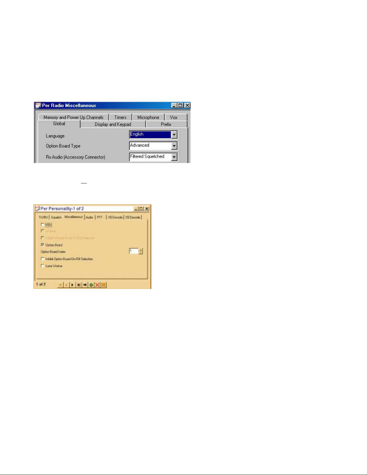
1. In the Per Radio Miscellaneous Window under the Global Tab, select “Advanced” as the “Option Board Type”
and set the RX Audio (Accessory Connector) to “Filtered Squelched”. Note: The Accessory Connector is the
rear accessory connector, but this setting also affects the audio going to the options connector.
2. For each personality, under the Miscellaneous tab, the “Option Board” must be enabled. Check the Option
Board box for all channels if using a button to control the repeat mode. If doing repeat on a per channel basis,
then check Option Board Feature only for repeat enabled channels. Additionally the unit should be
programmed to Power Up in Store/Retransmit Mode.
6
Page 7

Motorola CDM-1550-LS+, GM-338-LS Programming Instructions
It is necessary to program the radio before installing the unit. This is because the Option Board Feature of the
radio must be enabled in order to program the unit using the Motorola RIB box and cable or RIB-less cable and to
hear confirmation beeps from the radio after programming the unit.
Conventional Programming:
1. In the Radio Configuration Window under the Option Board Tab, select Advanced Option Interface as the
Option Board Type. Do not check the Option Board Configuration Download box.
2. When programming the “Conventional Personality”, check the Option Board Feature box for all channels if
using a button to control the repeat mode. If doing repeat on a per channel basis, then check Option Board
Feature only for repeat enabled channels. Additionally the unit should be programmed to Power Up in
Store/Retransmit Mode.
7
Page 8

LTR Programming:
1. In the LS Trunking Personality window, check the Option Board Feature box for each personality. Check the
Option Board Feature box for all channels if using a button to control the repeat mode. If doing repeat on a
per channel basis, then check Option Board Feature only for repeat enabled channels. Additionally the unit
should be programmed to Power Up in Store/Retransmit Mode.
The following step applies to the accessory connector and may be skipped by most users.
1. An accessory pin may be used to control the repeat enable/disable. This is useful in remote control
applications. To enable this feature, one of the radio accessory pins must be assigned to Option Board 1
(Input) via the CPS programmer. The MPS also needs to be configured to use this mode input (see page 17).
8
Page 9

Motorola GM-640, GM-660, GM-1280, MCX-720, MCX-760, MCX-780 Programming Instructions
It is necessary to program the radio before installing the unit. This is because the Option Board Feature of the
radio must be enabled in order to program the unit using the Motorola RIB box and cable or RIB-less cable and to
hear confirmation beeps from the radio after programming the unit.
1. In the Per Radio Parameters Window set the “Option Board Fitted Mode” as “Advanced”.
2. Edit the ‘MPT Personality’. In the “Options” window, check the “Option Board Enable” box. Check Option
Board Enable for all channels if using a button to control the repeat mode. If doing repeat on a per channel
basis, then check Option Board Enable only for repeat enabled channels. Additionally the unit should be
programmed to Power Up in Store/Retransmit Mode.
9
Page 10

3. If using conventional channels, edit the ‘Conventional Personality Data’. In the “Conventional Personality”
window, check the “Option Board Enable” box. Check Option Board Enable for all channels if using a button
to control the repeat mode. If doing repeat on a per channel basis, then check Option Board Enable only for
repeat enabled channels. Additionally the unit should be programmed to Power Up in Store/Retransmit Mode.
10
Page 11

HARDWARE INSTALLATION
Be certain to follow standard anti-static procedures when handling any of Midian’s products.
Radio Firmware: For the mobile radios listed, it is necessary to have radio firmware version R05.00.00 or higher.
If the radio has an older firmware version, it is necessary to upgrade to the newest firmware.
Verifying the firmware version can be done several ways. On most radios, this information is on a label on the
bottom of the radio. For display radios, selecting the SoftwareVer# option from the utility menu will report the
version. Consult Motorola if you cannot determine the firmware version.
Disassembling the Radio:
Additional disassembly instructions are also available in Motorola’s Basic Service Manual.
1. Disconnect power.
2. Remove plastic cover from the radio chassis by prying the sides away and lifting up.
3. Remove the 6 retaining bolts from the metal lid using a Torx™ size 20 screwdriver. Carefully begin removing
the lid. If there is already an option board installed such as a voice storage board, disconnect it by gently
lifting the latch holding the 40-pin flex cable in place.
4. Remove the lid completely. Unscrew the three bolts holding the option board frame to the lid if one is present.
Note: It is not recommended to use the radio for transmitting while disassembled, as some model radios require
the lid to be installed for RF power.
Installation:
1. Insert the 40-pin flex cable into the 40-pin flex connector on the SVR, making certain it is seated properly,
then close the latch. The silver foil side of the flex should face the edge of the board.
11
Page 12

2. The SVR is then mounted into the metal lid of the radio using the option board mounting kit. See pictures
below. The mounting kit is ordered from Midian as PRO Option B or from Motorola as RLN4823B. The
mounting kit includes the 40-pin flex cable, the mounting frame and 3 mounting screws.
Reassembling the Radio:
Additional assembly instructions are also available in Motorola’s Basic Service Manual.
1. Once the unit is installed in the lid, insert the other side of the 40-pin flex cable into the 40-pin flex connector
on the radio’s main board. The shiny side of the flex should face down.
2. Reinstall the metal lid making sure the flex bends toward the back of the radio, otherwise it will be pinched by
the lid. Tighten the screws down in number sequence shown on the lid to 17 in lbs (1.9 NM) torque. Repeat to
verify torque is correct after completing the sequence.
3. Snap on plastic cover.
12
Page 13

1B
PRODUCT PROGRAMMING
Install the MPS programming software if you have not done so already. The unit is programmed through the radio
using the Motorola RIB box and cable or RIBless cable and Midian’s MPS programming software.
Start the MPS software. From the product selection screen on the MPS software, locate and select the SVR-1MPP1/MPM1 and click OK.
Configure the programming software by selecting File->Preferences and make certain there is a check mark next
to ‘Rib Box Enable’ by clicking on it. Also select the appropriate COM port.
Set the parameters of the software to fit the application. If any clarifications on a feature are required, move the
mouse cursor over the feature name until the question mark appears and right click, an on-line help for that
feature will be shown. The MPS always defaults to “Conventional MDC Portable” as the radio type. On the basic
settings tab it is necessary to select the proper radio type.
After entering the parameters, save the file by going to File - Save As. Enter the file name in the File Name block
and click Save. Saving the file will allow for quick and easy reprogramming of units. Turn power on to the radio
and then the RIB. Click ProgramUnit! in the MPS software. You will hear 1-3 beeps from the radio if programmed
successfully.
To read the parameters from the unit, Click on ReadUnit!.
The radio and RIB should be powered down for 3 seconds after reading or programming.
Unit Information
This information area is updated when a unit is read or programmed. It will also be updated when a data file is
loaded from a
previous unit read and then saved. Below is a summary of the fields:
Product - Shows a more detailed description of the product model within the series.
uP #1 Firmware Version - Indicates the reported Firmware Version of the microcontroller of this product.
uP #1 Loader Version - Indicates the reported Loader Version of the microcontroller of this product.
13
Page 14

Power Up: Enables a short beep sequence that takes place immediately after power-up.
Error: This beep will be triggered by any input event which is not programmed. For example, if a long press on
the Mode Input is not assigned to a function, it will generate an error beep if a long press is sensed.
Mode: When using a switch to enable/disable the SVR, a medium tone followed by a high tone will sound
indicating repeat mode is enabled. When pressed again a medium tone followed by a low tone will sound
indicating repeat mode is disabled.
Go Ahead: Not currently used.
Wake Up Beep: Enables a short beep to be sent over the air immediately after PTT is pressed. Enabling this
beep is recommended when the 'Wake on VOX' feature is used. This may also be used to get the attention of the
party receiving a call.
Courtesy Beep: If selected, once the unit is done retransmitting the recorded audio it will generate a courtesy
tone to let others know it is done retransmitting.
Voice Compression: If checked the SVR-1 can store up to a 3-minute voice message. If unchecked the SVR-1
can store up to a 2.25 minute voice message, but with a higher level of audio quality.
14
Page 15

Power Up In Store/Retransmit Mode: If selected the unit will power up in repeat mode. This box must be
selected if doing repeat enable on a per-channel basis.
Key-Up Delay: This sets the amount of time the unit waits after keying the base station radio before it starts to
retransmit the recorded audio.
Trunking Delay Enable: Check this box if using a trunking system. This will cause the unit to hold off
regenerating the recorded audio until it has received a channel acquisition acknowledgement from the base
station radio. If no channel acquisition is received within 6 seconds the SVR-1 will cancel the retransmit cycle.
Common PTT: Check this box if PTT In and PTT Out are connected to the same point.
PTT Cancels Store/Retransmit: If checked and the PTT is pressed during store/retransmit the unit will not
retransmit the incoming transmission.
Number of Retransmits: This sets how many times the unit will retransmit the last recorded audio clip. Set to 0
for continuous transmission.
Retransmit Interval: This sets the time interval between the retransmits set in the Number of Retransmits field.
15
Page 16
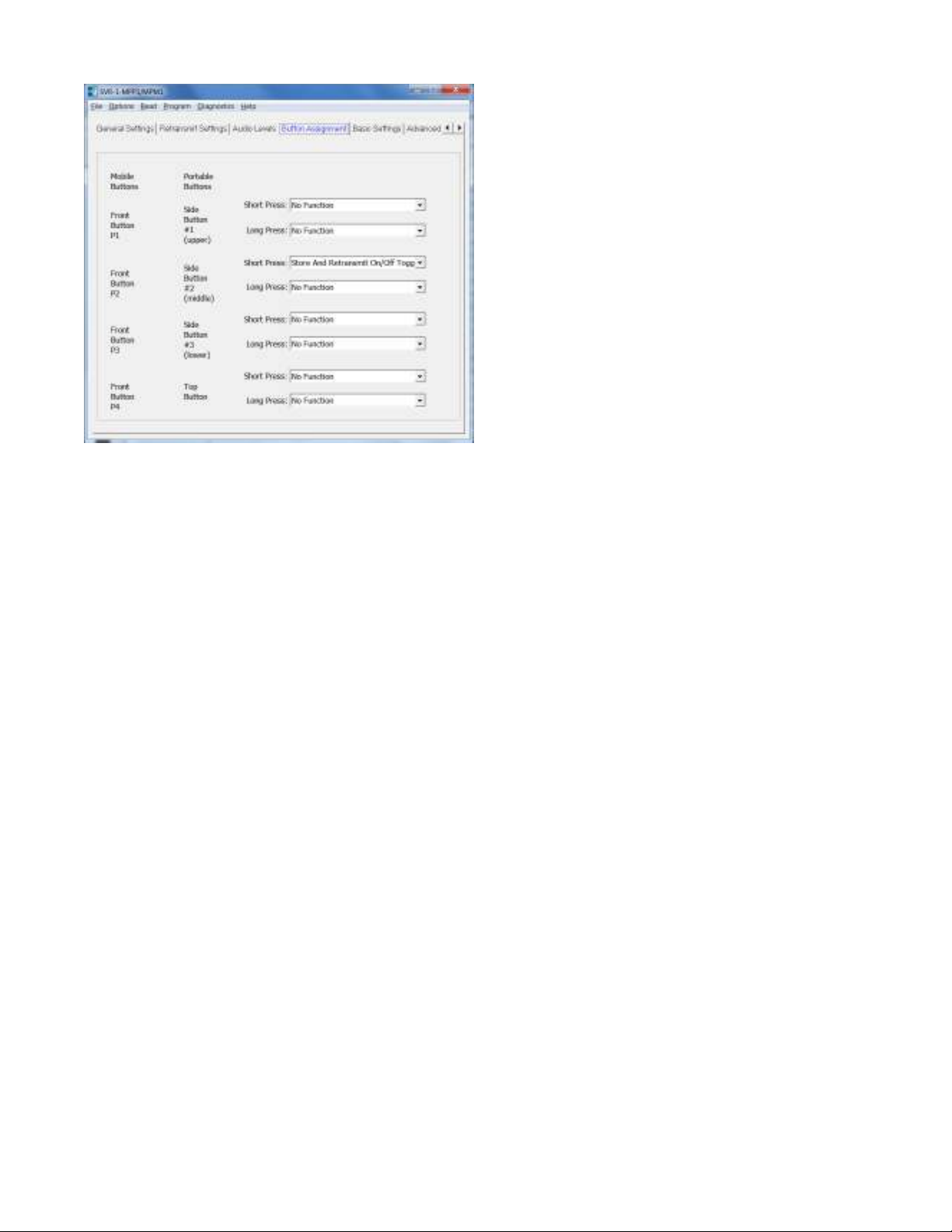
Short Press: If using a button for mode select, it can be programmed for Store and Retransmit On, Off or On/Off
Toggle. This is a press and immediate release.
Long Press: If using a button for mode select, it can be programmed for Store and Retransmit On, Off or On/Off
Toggle. This is a press and hold until beeps are heard, then release.
16
Page 17

Radio Type: Select from the list the Radio Type that matches your radio. For example if the radio is a CDM-750,
GM-140, GM-328 or PRO-5100 you would select Conventional MDC Mobile or if the radio is a GM-339 or GM660you would select MPT Mobile.
Enable Mode LED: Checking this box will cause the green LED on the radio to blink while the repeat mode is
enabled while the radio is idle. This blinking may be paused when the radio is receiving or transmitting in order to
avoid interfering with normal LED functions of the radio.
Enable LCD Messages: Future Use.
Use Accessory Pin for Mode Input (mobile only): If desired the unit can be enabled/disabled using an input
from the rear accessory connector of the mobile radio.
Use Accessory Pin for Emergency Input (mobile only): Future Use.
Please only adjust the parameters of this screen when advised to by Midian.
17
Page 18

Beep Volume: Adjust the slider for the desired beep volume. This level is expressed as a percentage of max
voice audio level.
Over-The-Air-Signal Modulation: Adjust the slider for the desired modulation of tones such as courtesy beep or
wake up beeps. This level is expressed as a percentage of max voice audio level.
Playback Level: This controls the audio level when a stored voice message is played back on the radio speaker.
If voice playback is too low or too loud, adjust this level accordingly.
Transmit Level: This controls the audio level when a stored voice message is retransmitted over the air. If the
transmit level is too low or too loud, adjust this level accordingly.
18
Page 19

HARDWARE ALIGNMENT
This section describes how to determine and set the audio levels. Midian has already determined the best audio
levels for some models of radios. These levels are on the following page in the tables. If you wish to alter the
levels please follow the instructions below.
Audio Levels Overview:
To ensure the best audio quality, the unit must be configured to match the audio levels used by the radio. The
SVR uses programmable gain amplifiers to accomplish this. Determining the gain settings for these amplifiers is
an involved process, so Midian simplified this process by developing an algorithm that requires the technician to
make only four voltage measurements. From these four measurements, all of the many internal settings are
determined.
Still, getting the best audio quality will likely require a bit of trial and error. The SVR only has control of audio
voltage levels, not input and output impedances. These impedances can dramatically influence the levels.
The Four Voltage Measurements:
An oscilloscope and a communications test set/service monitor are required for the measurements. It is
recommended that the measurements be recorded in units of mV peak-to-peak. Each measurement must be
taken with system modulation at either 60% or 100%, but Midian recommends using 60%
These measurements must be taken within 15 seconds of powering on the unit. This is because the unit will enter
power saving mode after that time. Measurements made while the unit is in power saving mode will not be valid.
TX Alignment Set-Up: A method for controlling transmit modulation is required for accurate measurements in the
TX mode. A small speaker held in place near the microphone by a rubber band can serve this purpose in most
cases. Use a sine-wave generator to inject a 1000 Hz tone into the speaker. Adjust the output of the sine wave
generator so that the transmitter produces 60% of rated modulation while PTT is pressed. Note that if the audio
source (such as a speaker) is moved even slightly, the TX modulation may change significantly. Care must be
taken to avoid changing the TX modulation while taking the measurements.
RX Alignment Set-Up: Using a service monitor send a fully quieting signal (-50 dBm) to the receiver with a 1000
Hz tone at 60% modulation, adjust the volume of the receiver to a comfortable listening level and measure the
audio level at the speaker using an AC coupled oscilloscope. Once the volume is adjusted and the measurement
taken do not adjust the volume control during the remainder of the alignment.
1. TX Input: The goal of this procedure is to determine the audio level that the unit will see at the TX audio
pickup point after it is installed. The unit must be installed and powered-on while making this measurement.
Use the TX Alignment Set-Up procedure and measure the audio level at TP1 on the unit.
2. RX Input: The goal of this procedure is to determine the audio level that the unit will see at the RX audio
pickup point after it is installed. The unit must be installed and powered-on while making this measurement.
Use the TX Alignment Set-Up procedure and measure the audio level at TP2 on the unit.
3. In the SVR programming software under audio levels set the TX In to the same level as measured in step 1
and for a preliminary adjustment set the TX Out for the same level. Set the RX In to the same level as
measured in step 2 and for a preliminary adjustment set the RX Out for the same level. Program the unit.
4. RX Output: The goal of this procedure is to determine the audio level that would normally appear at the RX
audio insertion point in an unmodified radio. Using the same RX Alignment Set-Up procedure verify the audio
level at the speaker is still at the same level measured initially in the RX Alignment Set-Up procedure. If not
adjust the RX Out level accordingly.
5. TX Output: The goal of this procedure is to determine the audio level that would normally appear at the TX
audio insertion point in an unmodified radio. Using the same TX Alignment Set-Up procedure verify the
modulation is still at 60%, if not adjust the TX Out level accordingly.
19
Page 20

Programming the Audio Levels:
Motorla
Radio Model
RX In
TX In
RX Out
TX Out
After determining the audio levels at the audio hookup points, it will be necessary to program the unit to match
these levels. In the programming software, there is a slider control on the Audio Levels Screen for each of the of
four audio hookup points. Locate the column that corresponds to the modulation and units of measurement for
each of the audio hookup points. Adjust the slider bar such that the value appearing in the appropriate column
matches what was measured as closely as possible.
The following table shows Midian’s recommended levels for the SVR at 60% modulation (mVpp) for tested
models of radios:
CDM-750, CDM-1250, GM-140, GM-160, GM-328, GM-338,
GM-398, PRO-3100, PRO-5100, PRO-7100
GM-340, GM-360, GM-380, GM-339, GM-399, PRO-7200 1044 222 240 216
GM-338-LS, CDM-1550-LS+ 678 138 150 138
GM-640, GM-660, GM-1280, MCX-720, MCX-760, MCX-780
876 216 192 222
20
Page 21

OPERATION
Mode Selection: Mode selection means a method of turning the simplex repeater on and off. In the SVR-1-
MPM1 series there are two ways of doing this:
Per-Channel Repeat On/Off: To use this feature each channel that is designated as a repeat channel should
have the Option Board Feature box enabled in the radio programming software. Channels that are designated as
non-repeat should NOT have the Option Board feature box enabled. Additionally the MPS software should be set
to Power Up in Store/Retransmit Mode. When using Per-Channel Repeat, a button should NOT be programmed
for Mode Select in the MPS software.
Repeat On/Off Button: To use this feature each channel should have the Option Board Feature box enabled in
the radio programming software. The desired button should be programmed to no function in the radio
programming software. In the MPS software on Button Assignment tab set the desired button to “Store/Retransmit
On or Off”. Pressing and releasing this button will toggle between repeat enable and disable. A medium tone
followed by a high tone indicates the unit is in repeat mode and a medium tone followed by a low tone indicates
the unit is in non-repeat mode.
21
Page 22

TECHNICAL NOTES
Radio Compatibility: Midian has taken the utmost care to ensure the option board integrates into the radio with
minimal impact to the features of the radio. However, some features may not be available in the radio when an
option board is used. If a feature is not available, please contact Midian to see if the feature can be added.
Radio Firmware: Midian recommends installing the module into the radio with the existing firmware of the radio
provided the firmware is at least R05.00.00. If the radio has a firmware version older than R05.00.00, it must be
upgraded. If there are any issues with the firmware then the firmware should be upgraded to the latest. However,
it should be noted that occasionally firmware updates may cause a conflict with proper option board/radio
communications. This may appear that the SVR is not working properly, but it is a conflict in the serial
communication between the option board and radio. Please note that firmware versions between the EMEA
region and the Asia and America regions might be different.
Accessory Pin Features: Upon power-up, the radio does not always report the state of the accessory pins to
the option board. It may be necessary to toggle the state of these inputs once after power-up to ensure correct
operation.
Option Board Feature: Enabling the option board feature tells the radio to report events such as button press,
PTT press, carrier detect, etc. to the option board. This feature enables communication between the option board
and the radio.
When controlling the SVR with a radio button, it is absolutely required to enable this feature on all channels. For
repeat enable/disable on a per channel basis only enable the option board on repeat channels and the power up
mode of the unit should be Power Up In Store/Retransmit Mode. On display models, the following icon appears
on the LCD when option board mode is on:
MIDIAN CONTACT INFORMATION
MIDIAN ELECTRONICS, INC.
2302 East 22nd Street
Tucson, Arizona 85713 USA
Toll-Free: 1-800-MIDIANS
Main: 520-884-7981
E-mail: HUsales@midians.comU
Web: HUwww.midians.comU
22
Page 23
1
1
2
2
3
3
4
4
5
5
6
6
D D
C C
B B
A A
47K
R2
+3.3V
560p
C1
+3.3V
560p
C2
47K
R7
47K
R6
560p
C4
100K
R15
100K
R14
+3.3VDD
.1u
C7
2R
R49
2R
R50
2R
R51
+3.3V
+3.3VA
+3.3VDD
8.2K
R16
27K
R13
.1u
C10
.01u
C9
4.7K
R8
+3.3V
VAN
.0068u
C15
.0068u
C16
56K
R18
36K
R21
.001u
C18
75K
R19
VAN
1.2M
R20
VAN
10K
R9
.1u
C12
VAN
100p
C14
10K1%
R11
10K1%
R12
10K
R10
39p
C44
+3.3V
+3.3V
.1u
C25
.01u
C21
560p
C19
VAN
TP8
TP18
TP7
TP6
TP17
TP5
TP12
TP3
TP4
TP1
TP2
.01u
C45
P4:1
P4:2
P4:3
P4:4
P4:5
P4:6
.1u
C28
.1u
C29
.1u
C30
.1u
C31
10u
C36
10u
C35
10u
C32
12p
C38
100p
C39
32 KHz
Y1
+3.3V
+3.3V
+3.3VDD
+3.3VA
+3.3V
VDDD
4.7K
R30
+3.3V
47K
R31
+3.3V
VDDD
VDDD
100K
R34
100K
R35
560p
C37
.1u
C41
10u
C40
+3.3V
SW_B+
SRD_SND
SCK_SND
100p
C617
VDDD
0R
R32
PTT_IN_OUT
4001
Q1
4001
Q2
*
Q6
0R
R52
SB1
D1
SB1
D2
SB1
D4
SB1
D3
560p
C11
0R
R57
0R
CR58
47K
R36 +3.3V
+3.3V
.1u
C43
SB1
D6
.1u
C42
RESET
CP
CJS
2009-03-25 AWS
2014-26-08
F-1
1 of 2
7701
SCHEMATIC
Copyright © 2014
MIDIAN ELECTRONICS, INC.
DATE:
DESIGN:
UPD BY:
REV:
APPR
REV
SHEET
PROJECT NUMBER
DOCUMENT NAME
VS SERIES PRO
2.2u
C13
SERIES VR2 VR3 U3 U6 U10
VS-1200/110/1100 Y Y Y * *
VS-1000
VS-1050
SVR-1/VM-3
TS-120
VAE-1
* * * * *
* * * * Y
* * * Y *
* * * * Y
* * *
Y
Y
* = NOT INSTALLED
Y = INSTALLED
R57
0R
0R
0R
0R
0R
225
R58
0R
0R
0R
0R
0R
*
*
*
*
*
*
R1
IN1
1
ENA
3
GND
2
RES
4
OUT
5
MIC5206 3.3V
VR1
IN1
1
ENA
3
GND
2
RES
4
OUT
5
MIC5206
VR2
IN1
1
ENA
3
GND
2
RES
4
OUT
5
MIC5206
VR3
.01u
C47
.22u
C33
0R
L1
2.2u
C27
2.2u
C26
22p
C24
3.3K
R24
*
R17
2.2u
C20
*
C52
-
+
2
3
1
411
LMV324
U7:1
-
+
6
5
7
LMV324
U7:2
-
+
9
10
8
LMV324
U7:3
-
+
13
12
14
LMV324
U7:4
3
1
2
4
5
6
U5
7
4
8
2 5
163
U4
161342
11
9
4
3
37
8
47
28
24
27
20
18
36
43
46
48
45
41
6
44
1
2
38
40
39
34
21
22
7
35
17
19
29
25
23
26
12
10
5
15
14
33
32
30
31
49
U1
CS
1
SO
2
SI
5
SCK
6
VCC
8
HOLD
7
WP
3
GND
4
AT26DF081A
U6
CS
7
SO
12
SI
13
SCK
14
DVDD
1
INT2
9
INT1
8
GND
2
AVDD
6
GND
5
IADDR0
4
3
10
11
MMA7455L
U10
16
15
33
35
36
37
38
3
11
12
20
46
21
2
39
40
41
42
32
31
13
10
451743
30
29
26
27
28
5
14
34
44
1
4
6
7
8
9
18
19
22
23
24
25
47
48
U3
*
C17
*
C48
*
C51
4.7K
R54
4.7K
R55
RDY
MISO
TX OUT
RX OUT
EXT MIC
OPT ENA
TX IN
RX IN
DIS IN
PTT_IN_OUT
VDDD
SW_B+
GND
-
+
33
11
4
52
LM321
U12
1K
R87
+3.3VA
.01u
C85
47p
C84
36K
R88
120K
R89
22K
R28
130K1%
R3
130K1%
R4
.0068u
C3
.0068u
C6
27K
R5
10K
R23
10K
R22
FLAT TX OUT
VDDD
22p
C8
P3:1
P3:2
P3:3
P3:4
P3:5
TABLE 1
R3
CJS CT-1
* * * * *
*
*
*
*
*
*
R5 R29
*
*
*
*
*
**
Y
*
0R
*
R29
Y
1
2
PROG IN
PROG OUT
P2
225
*
+
10u
C5
U12
Y
*
*
*
*
*
*
COTxt1
PIC4001 PIC4002
PIU1042
COU1
PIC4401
COC44
PIC4402
COC40
PIR3101
PIR3102
PIU1031
PIU1030
PIU1032
PIU1033
PIU1012
PIU1026
PIU1023
PIU1014
PIU1015
PIU105
PIU1010
PIU1025
PIU1049
COP3:1
PIP301
PIU1029
PIU1019
PIU1017
PIU1035
PIU1022
PIU1021
COTP12
PITP1201
PIU1034
PIU106
PIU1038PIU1039PIU1040
PIU1048
COC25
PIC2501 PIC2502
PIU407PIU408
PIU402
COU4
PIU401
PIU406
PIC1901
PIC1902
COTP8
PITP801
COR31
PIR3601 PIR3602
COU10
COP3:2
COP3:3
PIP302
PIP303
PIY102
PIY101
PIU1204
PIR8701
COR87
PIR8702
PIU404
PIU403
COTP18
PITP1801
COC19
COU6
PIU601
PIU602
PIU605
PIU606
COR36
PIU1007
PIU10012
PIU10013
PIU10014
PIU1008
PIU1009
COP3:4
COP3:5
PIP304
COY1
PIU1205
COU12
PIU1202
COR24
PIR2401 PIR2402
PIU405
COR17
PIR1701 PIR1702
PIC2001
COC20
PIC2002
PIU608
PIU607
PIU603
PIU604
PIP305
PIC3901
COC39
PIC3902
PIC3801
COC38
PIC3802
PIU1203
COR88
PIR8801 PIR8802
PIU1201
PIC8401
COC84
PIC8402
PITP701
COC21
PIC2101 PIC2102
PIU1001
PIU1006
PIU1004
PIU1003
PIU10010
PIU10011
PIU1005
PIU1002
PIC8501
COC85
PIC8502
PIR8901 PIR8902
PIC4201 PIC4202
PIC4301 PIC4302
COR89
COC42
COC43
PIR2801 PIR2802
PIC4501
PIC4502
PIR3001
COR30
PIR3002
COR28
COC45
PIP201
PIP202
PIU3016
PIU3015
PIU3048
PIU3037
PIU3035
PIU303
PIU3036
PIU3038
PIU3024
PIU3012
PIU3011
PIU3019
PIU3022
PIU3020
PIU3046
COP2
PIU3021
PIU3025
PIU3033 PIU3034
PIU3013
PIU3031PIU3032
PIU305
PIU3014
COU3
PIU3010
PIU3043
PIU3045
PIC2701
PIC2702
COR3
PIR301 PIR302
COTP7
COtb0sch1
COC36
PIC3601 PIC3602
COC35
PIC3501 PIC3502
COC33
PIC3301 PIC3302
PIU3044
PIU308
PIU3017PIU3018
PIC2601
COC27
PIC2602
PIC301
COC3
PIC302
COC41
COD6
PID601
PID602
PIU503
PIU501
PIR1902
PIU703
PIR2102
PIU702
PIC1801
PIC1802
PIC4101 PIC4102
PIU1024
PIU1013
PIU1011
PIU104
PIU103
PIU1037
PIU108
PIU1043
PIU1018
PIU1036
PIU109
PIU1028
PIU1046
PIU1027
PIU107
PIU1047
PIU1020
PIU1045
PIU1041
PIU1044
PIU101 PIU102
PIU505 PIU506
PIU504
COU5
PIU502
COR20
PIR2001 PIR2002
PIU704
PIU701
COU7:1
PIU7011
PIU1016
PIC5101
PIC5102
PIC61701
PIC61702
COD1
PID102
COD2
PID202
COD4
PID402
PIC201
COC2
PIC202
COR52
PIR5201 PIR5202
COC48
PIC4801 PIC4802
PIC101
PIC102
COR32
PIR3201 PIR3202
COC51
COC617
PID101
PID201
PID401
COD3
PID301
PID302
COC1
PIC401
COC4
PIC402
COR2
PIR201 PIR202
COTP1
PITP101
COTP2
PITP201
COR1
PIR101 PIR102
COTP17
PITP1701
PIC501
COC5
PIC502
COR7
PIR701 PIR702
COR6
PIR601 PIR602
PIR1501
COR15
PIR1502
PIVR101
PIVR103
PIVR201
PIVR203
PIVR301
PIVR303
PIVR104
PIVR105
COVR1
PIVR102
PIVR204
PIVR205
COVR2
PIVR202
PIVR304
PIVR305
COVR3
PIVR302
PIC4701 PIC4702
COC47
COR49
PIR4901 PIR4902
COR50
PIR5001 PIR5002
PIR1401
COR14
PIR1402
COR51
PIR5101 PIR5102
PIC701
PIC702
COC7
COC9
PIC901 PIC902
COC10
COR13
COR16
COTP5
PITP501
PIR801 PIR802
PIC1001
PIC1002
COTP6
PITP601
PIC1201 PIC1202
PIR1301
PIR1302
PIC1501 PIC1502
COC15
COC16
PIC1601 PIC1602
PIR1601
PIR1602
COR8
COC12
COR9
PIR901 PIR902
COR11
PIR1101 PIR1102
PIC1402
COC14
PIC1401
COC17
PIC1701 PIC1702
COR18
PIR1801 PIR1802
PIU706
COU7:2
PIU705
PIU707
PIR1001
PIU709
PIU7010
PIR1201
PIU7013
PIU7012
COC11
PIC1101 PIC1102
COR10
COU7:3
COR12
COU7:4
PIR1901
PIR2101
PIC1301
COC13
PIC1302
PIR1002
PIU708
PIR1202
PIU7014
COR19
COR21
COC18
PIU3030
PIU301
PIU3023
PIU3029
PIU304
PIU3026
PIU306
PIU307
PIU3027
PIU3047
PIU309
PIU3028
PIU3039
PIU3040
PIU3041
PIU3042
PIU302
COC26
PIL101
COL1
PIL102
PIC3101
PIC3201
COC31
COC32
PIC3202
PIP404
COP4:4
PIP403
COP4:3
PIP402
COP4:2
PIP401
COP4:1
PIP405
COP4:5
PIP406
COP4:6
PIR401 PIR402
PIR501 PIR502
PIC602
PIC601
PIR5701 PIR5702
PIC3102
COC30
PIC3001 PIC3002
COC29
PIC2901 PIC2902
COC28
PIC2801 PIC2802
COC6
PIR5401 PIR5402
PIR3401 PIR3402
COR34
PIR5501 PIR5502
PIR3501 PIR3502
COR35
COR4
COR5
COR57
COCR58
PICR5801 PICR5802
COR54
PIQ10G
COR55
PIQ20G
PIQ60G
PIC3701
COC37
PIC3702
PIR2201
COR22
PIR2202
PIR2901 PIR2902
PIR2301
COR23
PIR2302
COQ1
COQ2
COQ6
PIC801
COC8
PIC802
PIQ10D
PIQ10S
PIQ20D
PIQ20S
PIQ60D
PIQ60S
COR29
COTP3
PITP301
PIC2401
PIC2402
COTP4
PITP401
PIC5201
PIC5202
COC24
COC52
Page 24

1
1
2
2
3
3
4
4
5
5
6
6
D D
C C
B B
A A
100K
R633
100K
R646
100K
R632
100K
R648
100p
C616
VDDD SW_B+
1K
R6201KR6211KR6221KR6181KR6191KR623
GRN
D601
GRN
D602
GRN
D603
GRN
D604
GRN
D605
GRN
D606
__
B4
\|/
B5
+
B6
P1
B7
P2
B8
P3
B9
1
B10
2
B11
3
B12
4
B13
5
B14
6
B15
7
B16
8
B17
9
B18
*
B19
0
B20
#
B21
ROW_3 ROW_4 ROW_5
COL_5
COL_1 COL_2 COL_3
ROW_5
ROW_4
ROW_3
ROW_2
ROW_1
51.1K1%
R601
51.1K1%
R602
13K1%
R603
13K1%
R607
22.1K1%
R604
22.1K1%
R608
43.2K1%
R605
43.2K1%
R609
130K1%
R606
130K1%
R610
51.1K1%
R611
VDDD
VDDD
COL_1 COL_2 COL_3 COL_4 COL_5
ROW_1 ROW_2 ROW_3 ROW_5ROW_4
VDDD
47K
R649
3.3K
R647
SRD_SND
100p
C610
SW_B+
100p
C612
100p
C611
VDDD
VDDD
100p
C615
NOTE: * = NOT INSTALLED
D
A
C
D
B
A
61 2 3 4 5
1 2 3 4 5 6
CP
CJS
2009-03-25
AWS
2014-26-08
F-1
2 of 2
7701
SCHEMATIC
Copyright © 2014
MIDIAN ELECTRONICS, INC.
DATE:
DESIGN:
UPD BY:
REV:
APPR
REV
SHEET
PROJECT NUMBER
DOCUMENT NAME
VS SERIES PRO
B25
Q602
Y25
Q601
B25
Q603
560K1%
R612
1M
R613
*
C609
-
+
4
3
1
25
LMC7211
U602
LED ENABLE
LED BKLT ENA
KEY INTRP
100p
C613
RESET
* = NOT INSTALLED
Y = INSTALLED
D6
MPP1
D601 to D606
MPM1 Y
*
Y
*
J602
Y
*
U602
Y
*
TABLE 2
( aka KEY_ROW )
( aka KEY COL )
PIC61501
COC615
PIC61502
PIC61001
COC610
PIC61002
PIR63201
COR632
COR633
PIQ6020B
COR646
PIR63202
PIQ6020C
COQ602
PIQ6020E
PIR63301
PIR63302
PIR64601
PIR64602
PIC61301
COC613
PIC61302
PIQ6030B
PIC61601
COC616
PIC61602
COR647
PIR64701 PIR64702
PIR64801
COR648
PIR64802
PIQ6030C
COQ603
PIQ6030E
PIB401 PIB402 PIB403
COB4
PIB701 PIB702 PIB703
COB7
PIB1001 PIB1002 PIB1003
COB10
PIB1301 PIB1302 PIB1303
COB13
PIB501 PIB502 PIB503
COB5
PIB801 PIB802 PIB803
COB8
PIB1101 PIB1102 PIB1103
COB11
PIB1401 PIB1402 PIB1403
COB14
PIB601 PIB602 PIB603
COB6
PIB901 PIB902 PIB903
COB9
PIB1201 PIB1202 PIB1203
COB12
PIB1501 PIB1502 PIB1503
COB15
PIQ6010B
COR649
PIR64901 PIR64902
PIR62001
PIR62101
COR620
PIR62002
PID60101
COD601
PID60102
PIR62201
COR621
COR622
PIR62102
PIR62202
PID60301
COD603
PID60201
PID60302
COD602
PID60202
PIQ6010C PIQ6010E
COQ601
PIR61801
PIR61901
COR618
COR619
PIR61802
PIR61902
PID60501
COD605
PID60502
PID60401
COD604
PID60402
PIR62301
COR623
PIR62302
PID60601
COD606
PID60602
PIR60101
COR601
PIR60102
COC611
COC612
PIR60201
COR602
PIR60202
COR603
PIR60301 PIR60302
PIC61101
PIC61102
COR607
PIR60701 PIR60702
PIC61201
PIC61202
COR604
PIR60401 PIR60402
COR608
PIR60801 PIR60802
COR605
PIR60501 PIR60502
COR609
PIR60901 PIR60902
COR606
PIR60601 PIR60602
COR610
PIR61001 PIR61002
PIR61101
COR611
PIR61102
PIR61201
COR612
PIR61202
COU602
PIU60202
PIU60204
PIU60201
PIU60203
PIU60205
COR613
PIR61301 PIR61302
COC609
PIC60901 PIC60902
PIB1601 PIB1602 PIB1603
COB16
PIB1901 PIB1902 PIB1903
COB19
COtb0sch2
PIB1701 PIB1702 PIB1703
COB17
PIB2001 PIB2002 PIB2003
COB20
PIB1801 PIB1802 PIB1803
COB18
PIB2101 PIB2102 PIB2103
COB21
Page 25

COC616
PAVR203 PAVR201
COVR2
PAVR204
COR50
COC30
COC29
PAVO102 PAVO101
COC28
PAC3102
COC31
PAC3101
PAC702
COC7
PAC701
COR647
PAC61601PAC61602
PAQ6030B
COQ603
PAQ6030E
COR646
PAQ6020B
PAVO10B
COQ602
PAQ6020E
PAVO10E
COR611
PAR61201
COR612
PAR61202
PAVR202
PAR64701PAR64702
PAQ6010B
PAQ6030C
COQ601
PAQ6010E
COR633
PAR63301PAR63302
PAR64601PAR64602
PAQ6020C
PAR63202
PAVO10C
COR632
PAR63201
PAR61101PAR61102
PAU60203
PAU60204
PAU60202
COU602
PAU60201
PAU60205
COC20
PAC2001PAC2002
COC19
PAC1901PAC1902
PAVR205
PAR5001PAR5002
COR619
PAR61901 PAR61902
PAC3001PAC3002
PAC2901PAC2902
PAC2801PAC2802
PAC3202
COC32
PAC3201
PAL102
PAL101
COL1
PAU3024
PAVO1024
PAU3025
PAVO1025
PAU3026
PAVO1026
PAU3027
PAVO1027
PAU3028
PAVO1028
PAU3029
PAVO1029
PAU3030
PAVO1030
PAU3031
PAVO1031
PAU3032
PAVO1032
PAU3033
PAVO1033
PAU3034
PAVO1034
PAU3035
PAVO1035
PAU3036
PAVO1036
PAU3037
PAVO1037
COR649
PAR64901PAR64902
PAQ6010C
COR648
PAR64801PAR64802
PAR60202
PAC61202
COR602
PAR60201
COC612
PAC61201
COR601
PAR60101 PAR60102
PAC60901
PAR61301
COR613
COC609
PAC60902
PAR61302
PATP1801
COR17
COTP18
PAR1701 PAR1702
COC21
PAC2101 PAC2102
COR24
COTP7
PATP701
PAU3023 PAU3022
PAU3021 PAU3020 PAU3019 PAU3018 PAU3017 PAU3016 PAU3015
PAVO1022PAVO1023
COU3
PAU3038
PAVO1038
PAVO1039 PAVO1040 PAVO1041 PAVO1042 PAVO1043 PAVO1044 PAVO1045 PAVO1046
PAC2701 PAC2702
COP4
COVO1
PAP404
PAP406 PAP403PAP405
PAP402
PAP401
COR606
COR605
PAR60501 PAR60502
COR604
COR603
PAR60301 PAR60302
COR610
PAR60601PAR60602
COR609
PAR60901 PAR60902
COR608
PAR60401PAR60402
COR607
PAR60701 PAR60702
PAC61101
COC611
PAC61102
COR638
COR631
PAR62302
COC613
COR623
PAR62301
COC18
COR21
PAR2101 PAR2102
COR19
PAR1901 PAR1902
PAU401
PAU402
COU4
PAU403
PAU404 PAU405
PAR2401PAR2402
COC26
PAC2601 PAC2602
COC27
PAC3501
COC35
PAC3502
PAC1602
PAR1602
COR16
COC16
PAC1601
PAR1601
PAU3014 PAU3013
PAVO1013PAVO1014
PAVO1015PAVO1016PAVO1017PAVO1018PAVO1019PAVO1020PAVO1021
PAU3012
PAVO1012
PAU3011
PAVO1011
PAU3010
PAVO1010
PAU309
PAVO109
PAU308
PAVO108
PAU307
PAVO107
PAU306
PAVO106
PAU305
PAVO105
PAU304
PAVO104
PAU303
PAVO103
PAU302
PAU301
PAU3048PAU3047
PAU3046PAU3045PAU3044PAU3043PAU3042PAU3041PAU3040PAU3039
PAVO1047 PAVO1048
COR14
PAR1401 PAR1402
PAC3301
PAC3601
PAR5102
COC33
COR51
COC36
PAC3302
PAC3602
PAR5101
PAR61001PAR61002
PAJ6020A
PAVO10A
PAR60801PAR60802
PAR63801PAR63802
PAR63101PAR63102
PAC61301PAC61302
COJ602
PAC1801PAC1802
PAJ6020B
PAR2002
COR20
PAU701
PAR2001
PAU702
PAU703
PAU408
PAU407
PAU704
PAU406
PAU705
PAU706
PAU707
PAC1502
COC15
PAC1501
PAC4502
COC45
PAC4501
PAR2801
COR28
PAR2802
COR18
PAR1302
COC17
COR13
PAR1301
COC10
PAR8802
PAR8901
COR88
COR89
PAR8801
PAR8902
PAU1203
PAU1202
PAU1201
COU12
PAU1204
PAU1205
PAVR304
PAVR305
COVR3
PAVR301
PAR1501
COR15
PAVR303
PAVR302
PAR1502
PAJ602018
PAJ602017
PAJ602016
PAJ602015
PAJ602014
PAJ602013
PAJ602012
PAJ602011
PAJ602010
PAJ60209
PAJ60208
PAJ60207
PAJ60206
PAJ60205
PAJ60204
PAJ60203
PAJ60202
PAJ60201
COC610
COR12
COTP8
PATP801
PAR1801PAR1802
PAC1701PAC1702
PAC1001PAC1002
PAC8401
COC84
PAC8402
COR87
PAR8702 PAR8701
PAC4702
COC47
PAC4701
PAR1201
COU7
COR11
PAR1101PAR1102
COC11
PAC1101 PAC1102
COTP5
PAC902
PATP501
COC9
PAC901
PAC8502
PAU1008
PAU1009
COC85
PAC8501
PAU10010
COU10
PAU10011
PAU10012
PAU10013
PAC4301
PAP202
COC43
PAC4302
COR625
PAR62501 PAR62502
PAR61801
COR618
PAR61802
PAR62901
COC44
COR629
PAR62902
PAC61002
PAC61001
PAR1202
PAU7014
PAU7013
PAU7012
PAU7011
PAU7010
PAU709
PAU708
COR622
PAR62201 PAR62202
COR8
PAR801
PAR802
COR36
PAR3601 PAR3602
PAU1007
PAU1006
PAU1005
PAU1004
PAU1003
PAU1002
PAU1001
PAU10014
COP2
PAC4401PAC4402
COTP6
PAC1401
PATP601
COC14
PAC1402
PAC1201
COR4
COC12
PAC1202
COC3
PAR901
COR9
PAR902
PAR302
PAR1001
COR3
PAR301
COR10
PAR1002
COD6
PAD601PAD602
PAU106
PAU107
PAU108
PAU109
PAU1010
PAU1011
PAU1012
PAU1013
PAU1014
PAU1015
PAU1049
PAVO1049
PAU1016
PAU1017
PAU1018
PAU1019
PAR3002
COC41
COR30
PAR3001
PAC3902
PAY102
COC39
PAC3901
PAP201
PAC61502
PAR63001
COC615
COR630
PAC61501
PAR63002
PAC2501
PAR3501
PAQ20G
PAVO10G
COQ2
PAQ20S
PAVO10S
COR35
PAR3502
COD4
PAD401 PAD402
COR57
PAC601
PAR5701 PAR5702
COR5
PAC602
COC6
COR23
PAR2202
PAR402PAR401
COR22
PATP401
PAR2201
PAC302PAC301
PAU501
PAU502
COU5
PAU102
PAU103
PAU104
PAU105
COU1
PAU1020
PAU1021
PAU1022
PAU1023
PAC4101PAC4102
COY1
COP3
PAP304
COTP4
COCR58
PACR5801
PAU506
PAU505
PAU504PAU503
PAU101
PAU1048
PAU1047
PAU1046
PAU1045
PAU1044
PAU1043
PAU1042
PAU1031
PAU1030
PAU1029
PAU1028
PAU1027
PAU1026
PAU1024 PAU1025
PAC3802
COC38
PAC3801
PAY101
PAP303PAP305
PAP302
PAP301
COC25
PAC2502
COR55
PAQ20D
PAVO10D
PAC2401
COC24
PAC2402
COTP3
PAR502PAR501
PATP301
PAR2302PAR2301
COR29
PACR5802
PAU1041
PAU1040
PAU1039
PAU1038
PAU1037
PAU1036
PAU1035
PAU1034
PAU1033
PATP1201
PAU1032
COTP12
COR31
PAR3101 PAR3102
PAU601
PAU602
PAU603
PAU604 PAU605
COD2
PAD201 PAD202
PAR5501PAR5502
PAR201
COR2
PAR202
PAR102
COR621
PAR101
COR1
PAC3701
PAQ60G
COQ6
COC37
PAQ60S
PAC3702
COC1
PAC101PAC102
PAC801
PAR2902PAR2901
PAC802
COC8
PAC5201
COC2
COC52
PAC5202
PAC202
PAR601
PAR701
COR6
COR7
PAR602
PAR702
COC13
PAC1301
PAC1302
COC40
PAC4001 PAC4002
PAVR104
PAR4902
COVR1
COR49
PAR4901
PAVR105
COC42
PAC4201 PAC4202
COU6
PAD101
COD1
PAD102
PAR62101PAR62102
PAD301
COD3
PAQ60D
PAD302
COR54
PAR3401
PAQ10G
PAQ10S
COR34
PAR3402
PAC201
COC48
COR52
PATP201
COTP2
COR620
COC4
PAVR103
PAVR102
PAVR101
PAU608
PAU607
PAU606
PAJ601040
PAJ601038
PAJ601036
PAJ601034
PAJ601032
PAJ601030
PAJ601028
PAJ601026
PAJ601024
PAJ601022
PAJ601020
PAJ601018
PAR5401PAR5402
PAJ601016
PAJ601014
PAQ10D
COQ1
PAJ601012
PAJ601010
COTP1
PATP101
PAJ60108
PAJ60106
PAC4801PAC4802
PAJ60104
PAR5201PAR5202
PAJ60102
COJ601
PAR62001PAR62002
COTP17
PATP1701
PAC401PAC402
COR32
PAR3201PAR3202
PAC501
COC5
PAC502
PAC5101
PAC5102
COC51
PAJ6010APAJ6010B
PAJ601039
PAJ601037
PAJ601035
PAJ601033
PAJ601031
PAJ601029
PAJ601027
PAJ601025
PAJ601023
PAJ601021
PAJ601019
PAJ601017
PAJ601015
PAJ601013
PAJ601011
PAJ60109
PAJ60107
PAJ60105
PAJ60103
PAJ60101
PAJ6010CPAJ6010D
PAC61701
COC617
PAC61702
COtb0sch1
Page 26

COVO4
PAB1903
PAB2003
PAB2103
PAB1902
COB19
PAB1901
PAB2002
COB20
PAB2001
PAD60102 PAD60101
PAB2102
COB21
PAB2101
COD602
PAD60201PAD60202
COD601
PAB1603
PAB1703
PAB1803
PAB1602
COB16
PAB1601
PAB1702
COB17
PAB1701
PAB1802
COB18
PAB1801
PAB1303
PAB1403
PAB1503
PAB1302
COB13
PAB1301
PAB1402
COB14
PAB1401
PAB1502
COB15
PAB1501
COB10
PAB1003
COD604
PAD60401 PAD60402
COB11
PAB1103
COD603
PAD60302PAD60301
COB12
PAB1203
PAB1002
PAB1001
PAB1102
PAB1101
PAB1202
PAB1201
PAB803
PAB703
PAB903
COB7
PAB701
PAB802
COB8
PAB801
COB9
PAB901
PAB702
COD606
PAD60601 PAD60602
COD605
PAD60502PAD60501
PAB902
PAB403
PAB503
PAB603
PAB402
COB4
PAB401
PAB502
COB5
PAB501
PAB602
COB6
PAB601
COtb0sch2
 Loading...