

Page 1

SVR-1-KW2
Simplex Repeater Maker
Manual Revision: 2015-11-13
Covers Software Revisions:
VS-1XXX: Rev A 01.31.00 & Higher
This manual & product supports the following radios:
Portables: TK-2170, TK-3170
1
Page 2

HARDWARE SPECIFICATIONS
Operating Voltage 4.75-9.5 VDC
Operating Current
Power Save Mode (COR Operation) 2.5 mA typical
Power Save Mode (VOX Operation) 10 mA typical
Repeat Operation 17.5 mA typical
Average w/COR Power Save (80-10-10 cycle) <5 mA
Average w/COR Power Save (90-5-5 cycle) <4 mA
Operating Temperature -30 - +60 C
Frequency Response 300-3000 Hz
Input Impedance >45 kΩ
Input Level (TX) 0.05-2.5 VPP
Input Level (RX) 0.05-2.5 VPP
Audio Output Impedance < 1200 Ohm
INSTALLATION OVERVIEW
1. Test the radio for functionality.
2. Program the SVR per the Product Programming Section of this manual.
3. Install the SVR into the radio per the Hardware Installation Section of this manual.
4. Program the radio per the Radio Programming Section of this manual.
*** Midian is not responsible for any damage/loss resulting from the use of Midian’s products.
2
Page 3

GENERAL INFORMATION
Midian’s SVR-1 is a simplex repeater maker that can be installed into a portable radio. The SVR-1 detects COR
or VOX from an incoming transmission and records the incoming audio (up to 3 minutes). When the COR or VOX
is no longer detected the SVR-1 keys the radio and retransmits the recorded audio. The SVR-1 enables users to
expand radio coverage into poor coverage areas.
3
Page 4
1B
PRODUCT PROGRAMMING
The SVR series are programmed using Midian’s KL-4F and the MPS software
Go to our website midians.com and under downloads> software download the latest MPS software version. If
using the supplied CD-ROM insert it into the PC’s CD-ROM drive. In the browser that will pop-up, install the MPS
programming software. Be certain that the “Install KL-4 USB Driver” box is checked during the installation
process.
Open Windows’ Control Panel and go to Device Manager.
Open Ports (COM& LPT) to identify the port assignment issued by computer. Plug in the KL4 programmer to the
USB port and the screen will flash and show the device location.
Open the software and choose product from product tree then set appropriate comport selection in the MPS
software as needed
After entering the parameters, save the file by going to File - Save As. Enter the file name in the File Name block
and click Save. Saving the file will allow for quick and easy reprogramming of units.
KL-4 Programming: The Yellow and Green KL-4 leads need to be connected to the unit for programming.
Connect the green KL-4 lead to the program in hole (see below), connect the yellow KL-4 lead to the program out
hole (see below) on the unit. The black lead does not need to be connected when using the KL-4. Plug the board
onto the KL-4 p-7 KW2 connector. Push and hold the power button on the KL-4 and wait three seconds, then
click “Program Unit” in the KL-3 software.
KL-4 Reading: The Yellow and Green KL-4 leads need to be connected to the unit for reading. Connect the
green KL-4 lead to the program in hole (see below), connect the yellow KL-4 lead to the program out hole (see
below) on the unit. The black lead does not need to be connected when using the KL-4. Plug the board onto the
KL-4. Push and hold the power button on the KL-4 and wait three seconds, then click “Read Unit” in the KL-3
software.
Program Out
Program In
4
Page 5

Store on COR/Store on VOX: Select the appropriate method that the unit should use to start recording incoming
audio.
COR Hold-Up Time This sets the amount of times after a loss of COR or VOX that the unit will wait until it
retransmits the recorded audio.
VOX Settings > Sensitivity: This is a threshold detection based on the energy level in the audio.
VOX Settings > Attack Time: This sets the minimum time before the unit will detect VOX based on the sensitivity
setting.
VOX Settings > Decay Time: This sets the time before the unit will drop the VOX detection. Be certain to set this
long enough so that you do not have drop outs between words or on brief pauses.
Beep Options > Power Up: Enables a short beep sequence that takes place immediately after power-up.
Beep Options > Error: This beep may be triggered by any input event if programmed to do so. For example, if a
long press on the Mode Input is not assigned to a function, it may be configured to generate the error beep.
Beep Options > Mode: Not used as the radio offers its own mode tones for the option board enable.
Beep Options > Go Ahead: Not currently used.
Beep Options > Wake Up Beep: Enables a short beep to be sent over the air immediately after PTT is pressed.
Enabling this beep is recommended when the 'Wake on VOX' feature is used. This may also be used to get the
attention of the party receiving a call.
Beep Options > Courtesy Beep: If selected, once the unit is done retransmitting the recorded audio it will
generate a courtesy tone to let others know it is done retransmitting.
Voice Compression: If checked the SVR-1 can store up to a 3-minute voice message. If unchecked the SVR-1
can store up to a 2.25 minute voice message, but with a higher level of audio quality.
5
Page 6
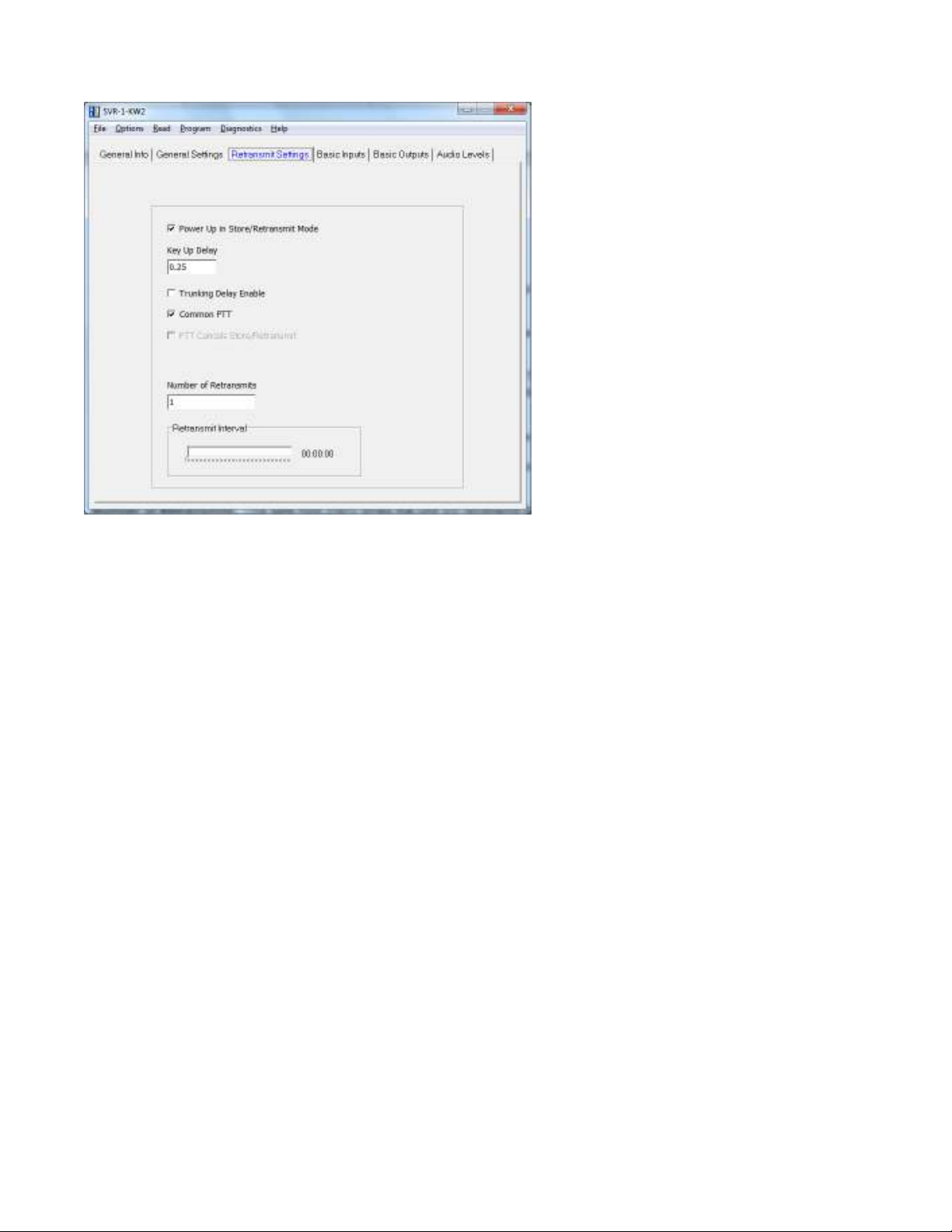
Power Up In Store/Retransmit Mode: If selected the unit will power up in repeat mode. This box must be
selected if doing repeat enable on a per-channel basis.
Key-Up Delay: This sets the amount of time the unit waits after keying the base station radio before it starts to
retransmit the recorded audio.
Trunking Delay Enable: Check this box if using a trunking system. This will cause the unit to hold off
regenerating the recorded audio until it has received a channel acquisition acknowledgement from the base
station radio.
Common PTT: Check this box if PTT In and Out are connected to the same point.
PTT Cancels Store/Retransmit: If checked and the PTT is pressed during store/retransmit the unit will not
retransmit the incoming transmission.
Number of Retransmits: This sets how many times the unit will retransmit the last recorded audio clip.
Retransmit Interval: This sets the time interval between the retransmits set in the Number of Retransmits field.
6
Page 7

PTT > Active Polarity: This sets whether the unit looks for an active low or active high to cancel a
store/retransmit.
PTT > Debounce: If checked the unit will require a continuous active state for 30 msec before accepting the PTT.
Mode > Type: Select whether the switch is Momentary or Latched. In this case it should be Latched.
Mode > Active Polarity: Select the active polarity of the mode switch. In this case it should be Low.
Mode > Debounce: If checked the unit will require a continuous active state for 30 msec before accepting the
mode change.
7
Page 8

COR > Active Polarity: This sets whether the unit looks for an active low or active high to start recording the
received audio.
COR > Debounce: If checked the unit will require a continuous active state for 30 msec before accepting the
COR.
PTT > Active Polarity: This sets the polarity necessary for the unit’s PTT output to key the radio.
Audio Enable > Active Polarity: This sets the polarity necessary for the unit to enable the speaker of the radio to
pass beeps.
8
Page 9

Tones > Beep Volume: Adjust the slider for the desired beep volume. This level is expressed as a percentage of
max voice audio level.
Tones > Over-The-Air-Signal Modulation: Adjust the slider for the desired beep volume. This level is expressed
as a percentage of max voice audio level.
Playback > Playback Level: This controls the audio level when a stored voice message is played back on the
radio speaker. If voice playback is too low or too loud, adjust this level accordingly.
Playback > Transmit Level: This controls the audio level when a stored voice message is retransmitted over the
air. If the transmit level is too low or too loud, adjust this level accordingly.
9
Page 10

AUDIO LEVELS ALIGNMENT
Midian recommends using the default programming file, which can be found in (C:\Program
Files\Midian\MPS\MPS_v5_xx\Additional Default Files) after installing the latest MPS software.
This section describes how to determine and set the audio levels.
Audio Levels Overview:
To ensure the best audio quality, the SVR must be configured to match the audio levels used by the radio. The
SVR uses programmable gain amplifiers to accomplish this. Determining the gain settings for these amplifiers is
an involved process, so Midian simplified this process by developing an algorithm that requires the technician to
make only four voltage measurements. From these four measurements, all of the many internal settings are
determined.
Still, getting the best audio quality will likely require a bit of trial and error. The SVR only has control of audio
voltage levels, not input and output impedances. These impedances can dramatically influence the levels.
The Four Voltage Measurements:
An oscilloscope and a communications test set/service monitor are required for the measurements. It is
recommended that the measurements be recorded in units of mV peak-to-peak. Each measurement must be
taken with system modulation at either 60% or 100%, but Midian recommends using 60%
A method for controlling transmit modulation is required for accurate measurements in the TX mode. A small
speaker held in place near the microphone by a rubber band can serve this purpose in most cases. Use a sinewave generator to inject a 1000 Hz tone into the speaker. Adjust the output of the sine wave generator so that the
transmitter produces 60% of rated modulation while PTT is pressed. Note that if the audio source (such as a
speaker) is moved even slightly, the TX modulation may change significantly. Care must be taken to avoid
changing the TX modulation while taking the measurements.
The first two measurements must be taken using a radio that has not been modified. The 2nd two measurements
require that the SVR is installed and power is applied to the radio/SVR. These measurements must be taken
within 15 seconds of powering the SVR on. This is because the SVR may enter power saving mode after that
time. Measurements made while the SVR is in power saving mode will not be valid. The unit ships with the power
save feature enabled by default. The power save feature can be disabled via the KL-3 programming software so
that it will not interfere with taking measurements, if desired. Please note that the levels provided to the option
board are different between narrow band and wide band.
1. RX Output: The goal of this procedure is to determine the audio level that would normally appear at the RX
audio insertion point in an unmodified radio. With a fully quieting signal modulated with a 1000 Hz tone at
60%. Measure the voltage level appearing at the junction of R-167 and R-169.
2. TX Output: The goal of this procedure is to determine the audio level that would normally appear at the TX
audio insertion point in an unmodified radio. Provide the radio an audio source generating a 1000 Hz tone and
key the radio. Adjust the audio source such that the modulation is at 60%. Measure the voltage level
appearing at R-170 on the radio.
3. RX Input: The goal of this procedure is to determine the audio level that the unit will see at the RX audio
pickup point after it is installed.
The unit must be installed and powered-on while making this measurement. Modulate a 1000 Hz tone at 60%.
Measure the audio level at TP2 on the unit.
4. TX Input: The goal of this procedure is to determine the audio level that the unit will see at the TX audio
pickup point after it is installed.
10
Page 11

The unit must be installed and powered-on while making this measurement. Provide the radio the same audio
Radio Model
RX In
TX In
RX Out
TX Out
source and level as in Step 2, generating a 1000 Hz tone and key the radio. Measure the audio level at the
TP1 on the unit.
Programming the Audio Levels:
After determining the audio levels at the audio hookup points, it will be necessary to program the SVR to match
these levels. In the programming software, there is a slider control on the Audio Levels Screen for each of the of
four audio hookup points. Locate the column that corresponds to the modulation and units of measurement for
each of the audio hookup points. Adjust the slider bar such that the value appearing in the appropriate column
matches what was measured as closely as possible. Midian recommends the following values based on 60%
modulation:
TK-2170, TK-3170 756 186 786 186
11
Page 12

HARDWARE INSTALLATION
Be certain to follow standard anti-static procedures when handling any of Midian’s products. Due to the design of
the options connector in the radio it is necessary to install two wires from the SVR-1-KW2 to the Kenwood radio.
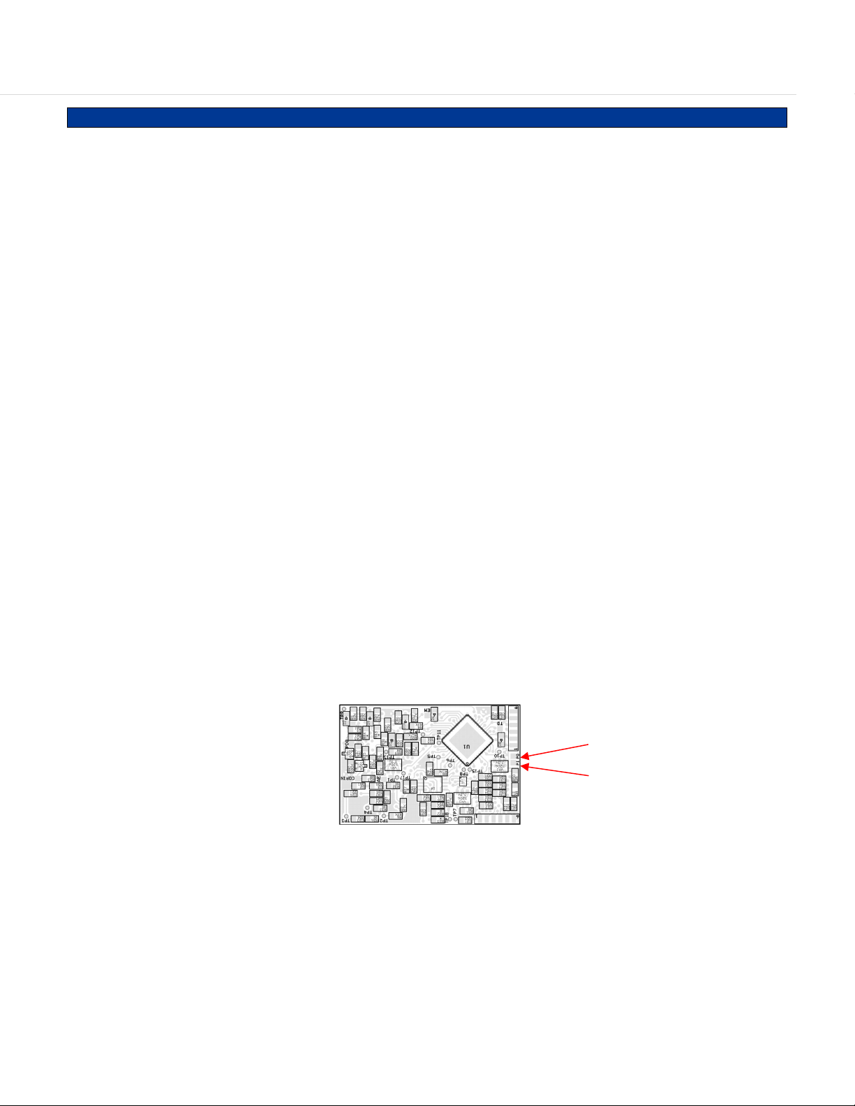
PTT: In order to be able to automatically key the radio it is necessary to install a wire from the point shown in the
picture below to a point in the radio as discussed in the installation instructions for the desired model radio.
COR: In order to start recording the SVR-1 can look for COR or VOX. Midian recommends using COR rather than
VOX. COR is not brought up to the options connector so it is necessary to run a wire from the point shown in the
picture above to a point in the radio as discussed in the installation instructions for the desired model radio.
SVR-1-KW2 PTT Pad
Empty pad of R46
SVR-1-KW2 COR Pad
12
Page 13

Be certain to follow standard anti-static procedures when handling any of Midian’s products.
TK-2170/3170:
This radio requires radio firmware version 1.22.00 (checksum 08C3) or higher.
1. Remove R-170 to open the radio’s TX path and R-167 to open the radio’s RX path.
2. Solder a jumper from pad SP_M in the radio to the COR Input pad on the unit.
3. Plug the unit into the options connector, CN60.
Remove R-167 Remove R-170
Install jumper
from pad SP_M
to the COR pad
on the SVR
4. Solder the PTT wire described on the previous page to the junction of L3 and C28.
13
Page 14

RADIO PROGRAMMING
TK-2170/3170:
This radio requires KPG-101D v 2.20 or higher for programming.
1. Under the “Model” menu select “Product Information” and set “Optional Board” to “Voice Scrambler”.
2. Under “Edit” “Extended Function” disable the “Echo PTT”.
3. Under the “Edit” menu select “Key Assignment” and set “Side 1” or “Side 2” under the “Top/Side” tab as
“Scrambler”. This will set the button under the PTT as the repeater enable button.
4. If repeat on a per channel basis is desired or a combination of a mode button and per channel, then from the
“Zone Information” screen click on the “Channel Edit” button. Under “Scrambler Setting” enable the “Voice
Scrambler”. For repeat on a per channel basis, this will need to be done for each channel where repeat is
desired. If the box is checked, the radio will power up in repeat mode & when that channel is selected. When
per channel repeat is used, it is still possible to toggle in and out of repeat mode.
14
Page 15

OPERATION
SVR Operation:
Repeater Enable/Disable: Press the radio key that was assigned in the radio programming. A tone will be
emitted from the radio and the ◊ symbol will appear on the display of the radio indicating repeat mode. If repeat
on a per channel basis is being used, then switching between an enabled or non-enabled channel causes the ◊
symbol to appear or disappear.
Repeat: With the SVR enabled, when the unit detects COR or VOX (depending on programming) it will record the
incoming audio transmission. When COR or VOX drops for a preprogrammed amount of time, the unit will key the
connected transceiver and retransmit the recorded audio.
TECHNICAL NOTES
Radio Compatibility: Midian has taken the utmost care to ensure the option board integrates into the radio with
minimal impact to the features of the radio. However, some features may not be available in the radio when an
option board is used. If a feature is not available, please contact Midian to see if the feature can be added.
Button Presses: When the SVR-1-KW2 is enabled and a button on the radio is pressed the radio generates
beeps, which in turn causes the SVR to key the radio and generate the beeps over the air.
MIDIAN CONTACT INFORMATION
Midian Electronics, Inc.
2030 N. Forbes Blvd. #101
Tucson, Arizona 85745 USA
Orders: 1-800-MIDIANS
Phone: 520-884-7981 Fax:
520-884-0422
E-mail: sales@midians.com
Web: www.midians.com
15
Page 16

- This page intentionally left blank -
Page 17

5
OPT 3
OPT 3
D D
TRUNK DELAY
TRUNK DELAY
+3.3V
R2
D4
47KR247K
R450RR45
SB1D4SB1
+VIN
R37
.1uC3.1u
R1
47KR147K
R37
100K
100K
PAD2
PAD2
R40
R40
100K
100K
C3
R321KR32
TP2TP2
Q7
Q7
NTA4001
NTA4001
TP1TP1
1K
R7
47KR747K
R6
47KR647K
R35*R35
*
COR_IN
R36*R36
COR IN
COR IN
*
C2
560pC2560p
C42
C42
R331KR33
.1u
.1u
1K
+3.3V
TP9TP9
D2
SB1D2SB1
C1
0R
560pC1560p
D5
SB1D5SB1
P1-20
P1-20
MODE IN
MODE IN
P1-7
P1-7
OPT 5
OPT 5
P1-6
P1-6
OPT 6
OPT 6
P1-12
P1-12
C C
TXO
TXO
P1-18
P1-18
RXEO
RXEO
P1-9
P1-9
PTT IN
PTT IN
A_ROUTE
B_ROUTE
R46*R46
*
B B
P1-5
P1-5
N/C
N/C
P1-14
P1-14
N/C
N/C
P1-15
P1-15
N/C
N/C
TP10TP10
A A
+7.5V
+7.5V
GND
GND
P1-2
P1-2
P1-1
P1-1
TP17TP17
C4
560pC4560p
+VIN
C51uC5
1u
5
R15
R15
100K
100K
VR1
VR1
4
1
IN1
RES
OUT
3
ENA
GND
MIC5206
MIC5206
2
VR2
VR2
4
1
IN1
RES
OUT
3
ENA
GND
MIC5206
MIC5206
2
VR3
VR3
4
1
IN1
RES
OUT
3
ENA
GND
MIC5206
MIC5206
2
C47
C47
.22u
.22u
5
5
+3.3VDD
5
R492RR49
2R
R502RR50
2R
R14
R14
100K
100K
+3.3V
+3.3VA
R512RR51
2R
TP13TP13
C7
.1uC7.1u
+3.3VDD
P1-4
P1-4
TRUNK_DLY
+3.3V
R3
47KR347K
TP5TP5
C9
.01uC9.01u
C10
C10
.1u
.1u
D7
SB1D7SB1
PAD7
PAD7
EMER IN
EMER IN
TP6TP6
R13
R13
27K
27K
.0068u
.0068u
.0068u
.0068u
R16
R16
8.2K
8.2K
4
4
C12
C12
.1u
.1u
C15
C15
C16
C16
+3.3V
R39
R39
47K
47K
PAD1
PAD1
R8
4.7KR84.7K
VAN
R9
10KR910K
C14
C14
100p
100p
6
5
D8
SB1D8SB1
R18
R18
56K
56K
-
-
+
+
C17*C17
OPT 1
OPT 1
+3.3V
D6
SB1D6SB1
C13
C13
.1u
.1u
9
10
VAN
13
12
VAN
*
U7B
U7B
LMV324M
LMV324M
P1-3
P1-3
R41
R41
47K
47K
Q8*Q8
*
C11
C11
.0047u
.0047u
R10
R10
10K
10K
-
-
U7C
U7C
+
+
LMV324M
LMV324M
+3.3V
411
-
-
U7D
U7D
+
+
7
R4
47KR447K
R55*R55
*
8
14
LMV324M
LMV324M
VAN
D1
SB1D1SB1
+3.3V
AGND
R19
R19
75K
75K
R21
R21
36K
36K
+3.3V
R11
R11
10K1%
10K1%
R12
R12
10K1%
10K1%
R38
R38
47K
47K
TP11TP11
3
1
TP15TP15
C18
C18
.001u
.001u
11
9
4
3
37
8
18
28
24
27
43
36
46
12
47
20
45
41
+3.3V
U5U5
5
2
3
2
C41
C41
.1u
.1u
R20
1.2M
1.2M
1
6
R20
+3.3V
161342
2
4
+
+
U7A
U7A
-
-
LMV324M
LMV324M
U1U1
40
39
C44
C44
39p
39p
1
3
C40
C40
2.2u
2.2u
31
30
32
33
14
15
5
10
26
23
25
49
29
19
17
35
7
22
21
34
644
48
38
+3.3V
2 5
163
VAN
(SOURCE)
TP8TP8
3
+3.3V +3.3V
R31
R31
47K
47K
1
2
5
6
FACTORY
44
22
33
11
Y1Y1
TP12TP12
R28
R28
4.7K
4.7K
C45
C45
.01u
.01u
C25
C25
.1u
.1u
748
R24
R24
4.7K
U4U4
4.7K
R17*R17
*
TP18TP18
C19
C19
560p
560p
CS
SO
SI
SCK
55
C20
C20
2.2u
2.2u
C46
C46
.1u
.1u
8
VCC
7
HOLD
3
WP
4
GND
U6*U6
*
C39
C39
100p
100p
C38
C38
12p
12p
+3.3V
+3.3VDD
C36
C36
10u
10u
C35
C35
10u
10u
C34
C34
.1u
.1u
C33
C33
.1u
.1u
+3.3V
U3U3
DSP
C27
C27
2.2u
2.2u
TP7TP7
C21
C21
.01u
.01u
+3.3V
R23*R23
*
R22*R22
*
MIDIAN ELECTRONICS, INC.
MIDIAN ELECTRONICS, INC.
MIDIAN ELECTRONICS, INC.
12/16/2007
12/16/2007
12/16/2007
DATE
DATE
DATE
DESIGN
DESIGN
DESIGN
CJS
CJS
CJS
DWN. BY
DWN. BY
DWN. BY
REV.
REV.
REV.
2
+3.3V
R30
R30
4.7K
4.7K
R540RR54
TRUNK_DLY
0R
R42
R42
1.2M
1.2M
COR_IN
R52
R52
4.7K
4.7K
+3.3VA
L10RL1
0R
A_ROUTE
C31
C31
C32
.1u
.1u
C30
C30
.1u
.1u
C29
C29
.1u
.1u
C28
C28
.1u
.1u
C32
10u
10u
AGND
C37
C37
560p
560p
B_ROUTE
FACTORY
C26
C26
2.2u
2.2u
NOTES:
* = NOT INSTALLED
VS-1200
VS-1200
VS-1200
KW2
KW2
KW2
SIZE
SIZE
AS
AS
AS
07/04/2008 Copyright © 2008
07/04/2008 Copyright © 2008
07/04/2008 Copyright © 2008
2
SIZE
C
C
C
SCHEMATICAPPR.
SCHEMATICAPPR.
SCHEMATICAPPR.
PAD3
PAD3
PAD4
PAD4
PROG IN
PROG IN
D9
SB1D9SB1
D11
D11
SB1
SB1
PROG OUT
PROG OUT
C48
C48
.1u
.1u
R530RR53
0R
D10
D10
SB1
SB1
Q6
Q6
NTA4001
NTA4001
R261KR26
1K
R251KR25
1K
C23
C23
.1u
.1u
PAD8PAD8
C22
C22
.1u
.1u
R43*R43
R44*R44
1
*
*
PAD6
PAD6
AUDIO ENH
AUDIO ENH
R48*R48
R470RR47
0R
C43
C43
560p
560p
TP3TP3
REV
REV
REV
A-1
A-1
A-1
SHEET
SHEET
SHEET
1 1
1 1
1 1
1
*
of
of
of
P1-10
P1-10
PROG IN
PROG IN
P1-11
P1-11
PROG OUT
PROG OUT
P1-16
P1-16
SIDE TONE
SIDE TONE
P1-13P1-13
P1-8
P1-8
PTT OUT
PTT OUT
P1-17
P1-17
TXI
TXI
C24
C24
220p
220p
TP4TP4
P1-19
P1-19
RXEI
RXEI
FILE NAME
FILE NAME
FILE NAME
sch_509_A1
sch_509_A1
sch_509_A1
DOCUMENT NUMBER
DOCUMENT NUMBER
DOCUMENT NUMBER
509-A-1
509-A-1
509-A-1
Page 18

- This page intentionally left blank -
Page 19

Page 20

 Loading...