

Page 1

SVR-1-IC1
Simplex Repeater Maker for Icom Two-Way Radios
Manual Revision: 2013-07-23
Covers Firmware Revisions:
VS-1XXX
Covers Hardware Revisions:
VS-IC1: 7710B & Higher
This manual & product supports the following Icom two-way radios:
Portables: F-3, F-3G, F-4, F-4G, F-14, F-24, F-30, F-30G, F-40, F-40G, F-33G, F-43G, F-70, F-80
Mobiles: F-110, F-120, F-210, F-220, F-310, F-320, F-410, F-420, F-520, F-620, F-1020, F-2020, F-1720, F-1820
: 01.62.00 & Higher
1
Page 2

HARDWARE SPECIFICATIONS
Operating Voltage 4.75-9.5 VDC
Operating Current
Power Save Mode (COR Operation) 2.5 mA typical
Power Save Mode (VOX Operation) 10 mA typical
Repeat Operation 17.5 mA typical
Average w/COR Power Save (80-10-10 cycle) <5 mA
Average w/COR Power Save (90-5-5 cycle) <4 mA
Operating Temperature -30 - +60 C
Frequency Response 300-3000 Hz
Input Impedance >45 k
Input Level (TX) 0.05-2.5 VPP
Input Level (RX) 0.05-2.5 VPP
Audio Output Impedance < 1200 Ohm
INSTALLATION OVERVIEW
1. Test the radio for functionality.
2. Program the SVR per the Product Programming Section of this manual.
3. Install the SVR into the radio per the Hardware Installation Section of this manual.
4. Program the radio per the Radio Programming Section of this manual.
*** Midian is not responsible for any damage/loss resulting from the use of Midian’s products.
2
Page 3

GENERAL INFORMATION
Midian’s SVR-1 is a simplex repeater maker that can be installed into a mobile or portable radio. The SVR-1
detects COR or VOX from an incoming transmission and records the incoming audio (up to 3 minutes). When the
COR or VOX is no longer detected the SVR-1 keys the radio and retransmits the recorded audio. The SVR-1
enables users to create low-cost vehicular repeaters or expand radio coverage into poor coverage areas.
3
Page 4

PRODUCT PROGRAMMING
Midian’s SVR-1-IC1 is programmed via Midian’s KL-4F programming interface and the MPS software. Please
reference the KL-4F manual for setup instructions of the MPS software and the KL-4F hardware. From the
product selection screen in the software, select the SVR-1-IC1 from the list and click OK.
Set the parameters of the software to fit the application. If any clarifications on a feature are required, move the
mouse cursor over the feature name until the question mark appears and right click, a definition of the feature will
be shown.
After entering the parameters, save the file by going to File - Save As. Enter the file name in the File Name block
and click Save. Saving the file will allow for quick and easy reprogramming of units.
Programming: Plug the board onto the IC1 connector on the KL-4F. Press and hold the power button on the KL4F and click “Program Unit” in the MPS software. The ACK LED on the KL-4F will faintly flash if programmed
successfully.
Reading: Plug the board onto the IC1 connector on the KL-4F. Press and hold the power button on the KL-4F
and click “Read Unit” in the MPS software.
Note: Upon power up the unit will be awake for 15 seconds before going into Power Save mode.
After programming or reading the SVR-1 turn off the unit for 3 seconds and then turn back on.
4
Page 5

Store on COR/Store on VOX: Select the appropriate method that the unit should use to start recording incoming
audio.
COR Hold-Up Time This sets the amount of times after a loss of COR or VOX that the unit will wait until it
retransmits the recorded audio.
VOX Settings > Sensitivity: This is a threshold detection based on the energy level in the audio.
VOX Settings > Attack Time: This sets the minimum time before the unit will detect VOX based on the sensitivity
setting.
VOX Settings > Decay Time: This sets the time before the unit will drop the VOX detection. Be certain to set this
long enough so that you do not have drop outs between words or on brief pauses.
Beep Options > Power Up: Enables a short beep sequence that takes place immediately after po wer-up.
Beep Options > Error: This beep may be triggered by any input event if programmed to do so. For example, if a
long press on the Mode Input is not assigned to a function, it may be configured to generate the error beep.
Beep Options > Mode: When using a switch to enable/disable the SVR, a medium tone followed by a high tone
will sound indicating repeat mode is enabled. When pressed again a medium tone followed by a low tone will
sound indicating repeat mode is disabled.
Beep Options > Go Ahead: Not currently used.
Beep Options > Wake Up Beep: Enables a short beep to be sent over the air immediately after PTT is pressed.
Enabling this beep is recommended when the 'Wake on VOX' feature is used. This may also be used to get the
attention of the party receiving a call.
Beep Options > Courtesy Beep: If selected, once the unit is done retransmitting the recorded audio it will
generate a courtesy tone to let others know it is done retransmitting.
Beep Options > Enable Side Tone Pin: Must be checked to get mode beeps.
5
Page 6

Key-Up Delay: This sets the amount of time the unit waits after keying the base station radio before it starts to
retransmit the recorded audio.
Trunking Delay Enable: Check this box if using a trunking system. This will cause the unit to hold off
regenerating the recorded audio until it has received a channel acquisition acknowledgement from the base
station radio.
Common PTT: Check this box if PTT In and PTT Out are connected to the same point.
PTT Cancels Store/Retransmit: If checked and the PTT is pressed during store/retransmit the unit will not
retransmit the incoming transmission.
Number of Retransmits: This sets how many times the unit will retransmit the last recorded audio clip.
Retransmit Interval: This sets the time interval between the retransmits set in the Number of Retransmits field.
6
Page 7

PTT > Active Polarity: This sets whether the unit looks for an active low or active high to cancel a
store/retransmit.
PTT > Debounce: If checked the unit will require a continuous active state for 30 msec before accepting the PTT.
Mode > Type: Select whether the switch is Momentary or Latched. In this case it should be Momentary.
Mode > Active Polarity: Select the active polarity of the mode switch. In this case it should be Low.
Mode > Debounce: If checked the unit will require a continuous active state for 30 msec before accepting the
mode change.
7
Page 8

COR > Active Polarity: This sets whether the unit looks for an active low or active high to start recording the
received audio.
COR > Debounce: If checked the unit will require a continuous active state for 30 msec before accepting the
COR.
PTT > Active Polarity: This sets the polarity necessary for the unit’s PTT output to key the radio.
8
Page 9

Audio Enable > Active Polarity: This sets the polarity necessary for the unit to enable the speaker of the radio to
pass beeps.
Trunking Delay Input > Active Polarity: This sets whether the unit needs an active low or active high indication
from the radio to indicate a trunked channel has been established.
Trunking Delay Input > Debounce: If checked the unit will require a continuous active state for 30 msec before
accepting the channel acquisition.
9
Page 10
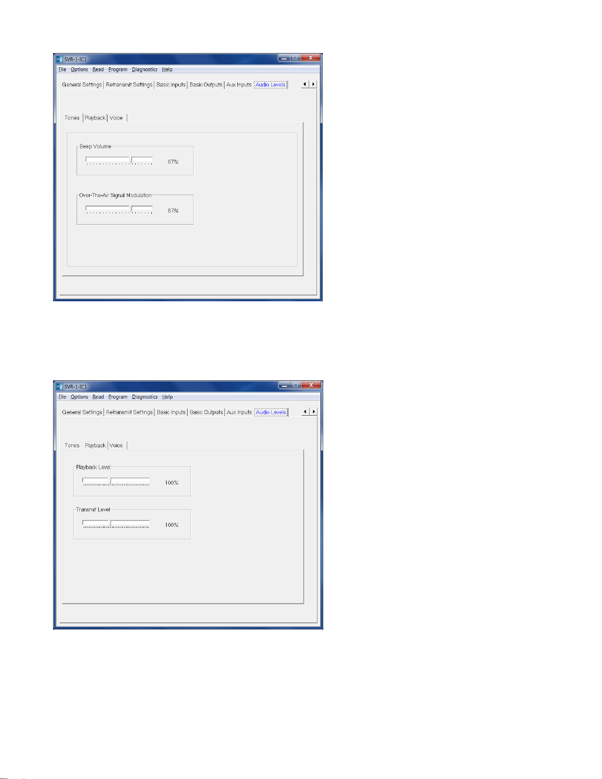
Tones > Beep Volume: Adjust the slider for the desired beep volume. This level is expressed as a percentage of
max voice audio level.
Tones > Over-The-Air-Signal Modulation: Adjust the slider for the desired beep volume. This level is expressed
as a percentage of max voice audio level.
Playback > Playback Level: Not used in this application.
Playback > Transmit Level: This controls the audio level when a stored voice message is retransmitted over the
air. If the transmit level is too low or too loud, adjust this level accordingly.
10
Page 11

AUDIO LEVELS ALIGNMENT
This section describes how to determine and set the audio levels.
Audio Levels Overview:
To ensure the best audio quality, the SVR must be configured to match the audio levels used by the radio. The
SVR uses programmable gain amplifiers to accomplish this. Determining the gain settings for these amplifiers is
an involved process, so Midian simplified this process by developing an algorithm that requires the technician to
make only four voltage measurements. From these four measurements, all of the many internal settings are
determined.
Still, getting the best audio quality will likely require a bit of trial and error. The SVR only has control of audio
voltage levels, not input and output impedances. These impedances can dramatically influence the levels.
Voltage Measurements:
An oscilloscope and a communications test set/service monitor are required for the measurements. It is
recommended that the measurements be recorded in units of mV peak-to-peak. Each measurement must be
taken with system modulation at either 60% or 100%, but Midian recommends using 60%
1. A method for controlling transmitter modulation is required for accurate measurements in the TX mode. A
small speaker held in place near the microphone by a rubber band can serve this purpose in most cases. Use
a sine-wave generator to inject a 1000 Hz tone into the speaker. Adjust the output of the sine wave generator
so that the transmitter produces 60% of rated modulation while PTT is pressed. Note that if the audio source
(such as a speaker) is moved even slightly, the TX modulation may change significantly. Care must be taken
to avoid changing the TX modulation while taking the measurements
2. Using a service monitor send a fully quieting signal (-50 dBm) to the receiver with a 1000 Hz tone at 60%
modulation, adjust the volume of the receiver to a comfortable listening level and measure the audio level at
the speaker using an AC coupled oscilloscope.
3. Set the radio programming software for an option board and set all parameters to accommodate the option
board then program the radio.
4. Install the unit and power up the radio, using the EXACT set up as in step 1 and while in transmit mode
measure the signal level at TP-1.
5. While in receive mode, and using the EXACT set up as in step 2, measure the signal level at TP-2.
6. In the KL3 under audio levels set the TX IN to the same level as measured in step 4, for a preliminary
adjustment set the TX OUT for the same level. Set the RX IN to the same level as measured in step 5 and for
a preliminary adjustment set RX OUT for the same level. Program the VS-1xxx.
7. Using the EXACT set up as in step1 and while in transmit mode verify the modulation is still at 60%, if not
adjust the TX OUT level accordingly.
8. While in receive mode, and using the EXACT set up as in step 2 verify the audio level at the speaker is the
same level that was measured in step 2, if not adjust the RX OUT level accordingly.
Programming the Audio Levels:
After determining the audio levels at the audio hookup points, it will be necessary to program the unit to match
these levels. In the programming software, there is a slider control on the Audio Levels Screen for each of the of
four audio hookup points. Locate the column that corresponds to the modulation and units of measurement for
each of the audio hookup points. Adjust the slider bar such that the value appearing in the appropriate column
matches what was measured as closely as possible.
11
Page 12

The following table shows Midian’s recommended levels in mVpp at 60% modulation for tested Icom models of
two-way radios:
Radio Model RX In TX In RX Out TX Out
F-3, F-4 408 42 480 48
F-3G, F-4G 1335 48 1395 48
F-14, F-24 576 42 684 48
F-30, F-40
F-30G, F-40G
F-33G, F-43G
F-70, F-80
F-110, F-120, F-210, F-220 684 180 684 222
F-310, F-320, F-410, F-420
F-520, F-620
F-1020, F-2020
F-1720, F-1820
12
Page 13

HARDWARE INSTALLATION
Be certain to follow standard anti-static procedures when handling any of Midian’s products.
Icom F-3:
Remove W2 to open the radio’s TX path, W10 to open the radio’s RX path, and W1 to open the radio’s PTT path.
Plug the unit into the options connector located behind the rubber stopper under the battery. These instructions
are for radio serial numbers 50,000 and higher.
Icom F-4:
Remove W2 to open the radio’s TX path, W12 to open the radio’s RX path, and W1 to open the radio’s PTT path.
Plug the unit into the options connector located behind the rubber stopper under the battery. These instructions
are for radio serial numbers 50,000 and higher.
Icom F-3G, F-4G:
Open jumper C to open the radio’s TX path, jumper F to open the radio’s RX path, and Jumper D to open the
radio’s PTT path. Plug the unit into the options connector located behind the rubber stopper under the battery.
Icom F-14, F-24:
The unit plugs into the options connector under the battery. Before plugging the unit in, open jumper MIC to open
the radio’s TX path, jumper DISC to open the radio’s RX path and jumper PTT to open the radio’s PTT path.
Icom F-30, F-40:
Open jumper CP C to open the radio’s TX path, jumper CP A to open the radio’s RX path, and jumper CP B to
open the radio’s PTT path. The unit plugs into the options connector located on the main board.
Icom F-30G, F-40G:
Open jumper B to open the radio’s TX path, jumper A to open the radio’s RX path, and jumper G to open the
radio’s PTT path. The unit plugs into the first options connector (labeled as Option One) located on the main
board.
Note: Some F-30G, F-40G radios have an issue that when jumper G is cut, the radio still does not open the PTT
path. If this occurs it will be necessary to program the unit as PTT Common with a low negative logic.
Icom F-33G, F-43G:
The unit plugs into the options connector under the battery. Before plugging the unit in, open jumper C to open
the radio’s TX path, jumper F to open the radio’s RX path, and jumper D to open the radio’s PTT path.
Icom F-70, F-80:
Before installing the unit, open the radio’s TX path by opening CP-1, open the RX path by opening CP-2, and
open the PTT path by opening CP-4. The unit plugs into the options connector located on the main board.
Icom F-120, F-220:
Before installing the unit, open the radio’s TX path by opening the MIC jumper, open the RX path by opening the
DISC jumper, and open the PTT path by opening the PTT jumper. The unit plugs into the options connector
located on the main board.
13
Page 14

Icom F-320, F-420, F-520, F-620:
Open jumper A to open the radio’s TX path, jumper B to open the radio’s RX path, and jumper C to open the
radio’s PTT path. The unit plugs into the options connector located on the main board.
Icom F-1020, F-2020:
Open jumper MIC to open the radio’s TX path, jumper AFO to open the radio’s RX path, and jumper PTT to open
the radio’s PTT path. The unit plugs into the options connector located on the main board.
Icom F-1720, F-1820:
Open jumper “IO MIC” to open the radio’s TX path, jumper “AF OUT” to open the RX path. Additionally close CP-
37. The unit plugs into the options connector located on the main board.
14
Page 15

RADIO PROGRAMMING
Icom F-3, F-4, F-30, F-40, F-320, F-420, F-1020, F-2020:
For mode select, program the radio’s option button (P0-P3) as Opt 1 Momentary/Active Low.
Icom F-3G, F-4G, F-14, F-24, F-33G, F-43G, F-70, F-80, F-120, F-220, F-520, F-620, F-1720, F-1820:
For mode select, program the radio’s option button under Common > Key & Display as OPT1 Momentary/L
(Active Low).
Icom F-30G, F-40G:
For mode select, program the radio’s option button under Common>Key & Display as OPT11 Momentary/L
(Active Low). If you use the second options connector, program as OPT21 Momentary/L (Active Low).
15
Page 16

OPERATION
SVR Operati
on:
Repeater Enable/Disable: Press the radio key that was assigned during installation and/or radio programming.
A medium tone followed by a high tone will sound indicating repeat mode is enabled. When pressed again a
medium tone followed by a low tone will sound indicating repeat mode is disabled.
Repeat: With the SVR enabled, when the unit detects COR or VOX (depending on programming) it will record the
incoming audio transmission. When COR or VOX drops for a preprogrammed amount of time, the unit will key the
connected transceiver and retransmit the recorded audio.
TECHNICAL NOTES
Radio Compatibilit
y: Midian has taken the utmost care to ensure the option board integrates into the radio with
minimal impact to the features of the radio. However, some features may not be available in the radio when an
option board is used. If a feature is not available, please contact Midian to see if the feature can be added.
MIDIAN CONTACT INFORMATION
MIDIAN ELECTRONICS, INC.
2030 N. Forbes Blvd. #101
Tucson, Arizona 85745 USA
Toll-Free: 1-800-MIDIANS
Main: 520-884-7981
E-mail: sales@midians.com
Web: www.midians.com
16
Page 17

1
1
2
2
3
3
4
4
5
5
6
6
D D
C C
B B
A A
P3-4
TCK
-
+
2
3
1
U7:1
P3-3
TMS
Y1
8C29666
P1-3
16
P5-1
13
VDD
42
P3-1
11
P3-5
9
P4-5
4
P4-7
3
P2-6
37
P3-7
8
P2-7
47
P3-6
28
P5-2
24
P3-4
27
P1-2
20
VSS
18
P2-4_AREF
36
P0-7
43
P0-1
46
P2-5
48
P0-3
45
P0-6
41
P4-1
6
P0-5
44
P2-31P2-1
2
P0-0
38
P0-440P0-2
39
P2-0
34
P1-4
21
P1-6
22
SMP
7
P2-2
35
P1-1
17
P1-0
19
XRES
29
P3-0
25
P5-0
23
P3-2
26
P5-3
12
P3-3
10
P4-3
5
P1-5
15
P1-7
14
P4-6
33
P4-4
32
P4-0
30
P4-2
31
PAD
49
U1
P3-2
TDI
*
IN1
1
ENA
3
GND
2
LVF
4
OUT
5
VR2
VDD
P2-5
P3-1
TDO
-
+
13
12
14
411
U7:4
-
+
9
10
8
U7:3
PROG OUT
PAD2
7427
SHDN
7
V+
4
CLK
8
IN2OUT
5
COM1OS6V-
3
U4
-
+
6
5
7
U7:2
PROG IN
PAD1
SDATA
P2-2
CLK
P2-1
IN1
1
ENA
3
GND
2
LVF
4
OUT
5
VR1
P3-6
GND
3157
Y0
3
Y1
1
GND
2
Z
4
VDD
5
S
6
U5
IN1
1
ENA
3
GND
2
LVF
4
OUT
5
VR3
XRES
P2-3
*
MISO0
16
SSO
15
XTAL
33
PWMA0
3
IRQA
11
FAULTA0
12
ANA0
20
CAN_RX
46
ANA1
21
RST
2
TCK
39
TMS
40
TDI
41
TDO
42
EXTAL32VSS31VSS13VSS10VSS
45
VCAP2
17
VCAP1
43
VDDADC
30
VSSADC
29
VREFIN
26
VREFMID
27
VREFP
28
VDD_IO5VDD_IO14VDD_IO34VDD_IO
44
U3
P3-5
RST
GND
P2-4
VAN
VAN
VAN
VAN
VAN
IN SYSTEM
SERIAL PROGR.
(SOURCE)
+3.3V
+3.3V
+3.3V
+3.3V
+3.3VA
+3.3VDD+VIN
+3.3V
+3.3V
+3.3V
+3.3V
+3.3V
+3.3V
+3.3VA
+3.3VDD
+3.3V+3.3V+3.3V
+3.3V
+3.3V
+3.3VDD
47K
R10
10K
R17
10K
R16
+5 VIN
+5 VIN
+5 VIN
+5 VIN
3.3KR20
4001
Q4
4001
Q3
4001
Q2
4001
Q1
100KR12
1KR24
1KR27
3.3KR28
75KR35
1.2M
R36
36KR40
56KR37
4.7KR6
47K
R3
*
R34
*
R38
8.2K
R41
27K
R32
10K1%R30 10K1%R31
10KR26
10KR25
4.7KR21
47K
R18
100K
R33
100K
R42
4.7K
R19
1KR11
1KR15
47KR8
47KR9
47KR5
47KR14
47KR13
2RR23
2RR29
2RR39
TP1
TP2
TP3
TP4
TP5
TP6
TP7
TP8
TP9
TP10
TP11
TP13
TP14
TP15
TP16
TP17
TP18
.1u
C6
.1u
C14
560p
C7
.1u
C9
560p
C19
.01u
C24
.1u
C29
.1u
C37
.1u
C46
.01u
C48
10u
C44
560p
C43
.0068u
C45
.0068u
C39
*
C40
.001u
C47
.01u
C36
.1uC32
2.2u
C42
560p
C41
.1u
C33
.1u
C31
560p
C27
100p
C38 39p
C35
.1u
C34
.1u
C28
220p
C30
.1uC21
.1u
C18
.1u
C17
.1u
C15
10u
C16
2.2uC26
2.2u
C25
560p
C22
560p
C23
.1u
C10
.1u
C11
10u
C12
10u
C13
12p
C8
100p
C5
.1u
C2
2.2u
C4
.1u
C3
.01u
C20
CS
7
SO
12
SI
13
SCK
14
DVDD
1
INT2
9
INT1/DRDY
8
GND
2
*
AVDD
6
GND
5
IADDR0
4
N/C
3
GND
10
GND
11
U8
*R10R
R2
*
R4
.1uC1+3.3V
EMER_IN
P1-10
EMER_IN
P1-10
MODE_IN
P1-9
MODE_IN
P1-9
COR_IN
P1-6
COR_IN
P1-6
TX_IN
P1-4
TX_IN
P1-4
RX_IN
P1-23
RX_IN
P1-23
+5 VIN
P1-29
+5 VIN
P1-29
+VIN
P1-28
+VIN
P1-28
GND
P1-12
GND
P1-12
GND
P1-30
GND
P1-30
PTT IN
P1-1
PTT IN
P1-1
RX_OUT
P1-22
RX_OUT
P1-22
TX_OUT
P1-3
TX_OUT
P1-3
PTT_OUT
P1-2
PTT_OUT
P1-2
AUDIO_ENABLE
P1-26
AUDIO_ENABLE
P1-26
N/C
P1-11
N/C
P1-11
BEEP OUT
P1-25
BEEP OUT
P1-25
PROG_OUT
P1-7
PROG_OUT
P1-7
PROG_IN
P1-5
PROG_IN
P1-5
N/C
P1-8
N/C
P1-8
N/C
P1-13
N/C
P1-13
N/C
P1-14
N/C
P1-14
N/C
P1-15
N/C
P1-15
N/C
P1-16
N/C
P1-16
N/C
P1-17
N/C
P1-17
N/C
P1-18
N/C
P1-18
N/C
P1-19
N/C
P1-19
N/C
P1-20
N/C
P1-20
N/C
P1-21
N/C
P1-21
N/C
P1-24
N/C
P1-24
N/C
P1-27
N/C
P1-27
LTR
TP22
4.7KR7
1N4735A
*
D5
NOTE
If Input Voltage, +VIN, is greater than +10 VDC:
- Cut SJ1 Jumper trace
- Install zener diode D5
TP12
CS
1
SO
2
SI
5
SCK
6
VCC
8
HOLD
7
WP
3
GND
4
AT26DF081A
U6
SJ1
MODE/CALL
PAD3
TP20
TP21
0R
R43
0R
R44
SB1
D1
SB1
D2
SB1
D3
SB1
D4
*
R22
CP
CJS
2010-12-24
DML
2013-04-05
B-2
1 of 1
7710
MIDIAN ELECTRONICS, INC.
DATE:
DESIGN:
DWN BY:
REV:
APPR
COPYRIGHT ©
REV
SHEET
PROJECT NUMBER
DOCUMENT NAME
SCHEMATIC
2013
SVR-1-IC1
VOICE OPTION
ACCELEROMETER OPTION
SERIES
VS-1200/1100/110
VS-1000/1050
TS-120
SVR-1/VM-3
VAE-1
VR2 VR3 U3 U6 U8
Y Y Y * *
* * * * *
* * * * Y
* * * Y *
* * * Y Y
Y = INSTALLED
* = NOT INSTALLED
NOTES
COTP11
PITP1101
COTP22
COP2:1
COP2:2
COP2:3
COP2:4
PITP2201
PIP1010
COP1:10
PIP109
COP1:9
PIP106
COP1:6
PIP104
COP1:4
PIP1023
COP1:23
PIP101
COP1:1
PIP108
COP1:8
PIP1011
COP1:11
PIP1013
COP1:13
PIP1014
COP1:14
PIP1015
COP1:15
PIP1016
COP1:16
PIP1017
COP1:17
PIP1018
COP1:18
PIP1019
COP1:19
PIP1020
COP1:20
PIP1021
COP1:21
PIP1024
COP1:24
PIP1027
COP1:27
PIP1029
COP1:29
PIP1028
COP1:28
PIP1012
COP1:12
PIP1030
COP1:30
PIC4301
COC43
PIC4302
COR43
PIR4301 PIR4302
COR44
PIR4401 PIR4402
COTP1
PITP101
COTP2
PITP201
COTP9
PITP901
COR19
COD5
PID50APID50K
COSJ1
PISJ101 PISJ102
COC7
PIR1901
COC19
PIR1902
COTP10
PIC4401
PIC4402
COTP20
PITP2001
COTP21
PITP2101
PIC701
PIC702
PIC1901
PIC1902
PITP1001
COTP17
PITP1701
PIVR101
PIVR103
PIVR201
PIVR203
PIVR301
COC44
PIVR303
PIR4201
COR42
PIR4202
COD1
COD2
COD3
COC6
PIC601 PIC602
COC14
PIC1401 PIC1402
COD4
COVR1
COVR2
COVR3
PID101PID102
PID201PID202
PID301PID302
PID401PID402
PIVR104
PIVR102
PIVR204
PIVR202
PIVR304
PIVR302
PIVR105
PIVR205
PIVR305
COR5
PIR501 PIR502
COR8
PIR801 PIR802
COR9
PIR901 PIR902
COR11
PIR1101 PIR1102
COR15
PIR1501 PIR1502
COR18
PIR1801 PIR1802
COR23
PIR2301 PIR2302
COR29
PIR2901 PIR2902
COR39
PIR3901 PIR3902
PIC2401
COC24
PIC2402
PITP501
COTP5
COTP13
PITP1301
PIC2901
COC29
PIC2902
COTP16
PITP1601
PIC3701
COC37
PIC3702
PIR3302
COR33
PIR3301
COTP14
PITP1401
PIC4601
COC46
PIC4602
PIC4801
COC48
PIC4802
COR13
PIR1301 PIR1302
COR14
PIR1401 PIR1402
COR21
PIR2101 PIR2102
PITP601
COTP6
COC31
PIC3101
PIC3102
PIC3301
COC33
PIC3302
PIR3201
COR32
PIR3202
PIR4101
COR41
PIR4102
COC3
PIC301 PIC302
PIU1013
PIU1011
PIU109
PIU1037
PIU108
PIU1027
PIU1028
PIU1010
PIU1024
PIU1043
PIU503
PIU501
PIU1036
PIU1018
PIU1049
PIU1046
PIU1047
PIU1020
PIU1045
PIU1041
PIU1044
COTP15
PIU505 PIU506
COU5
PIU502
PIR3502
PIR4002
COC47
PIU101 PIU102
PITP1501
PIU504
COR36
PIR3601
PIU703
PIU702
PIC4701
PIC4702
COR22
PIR2201PIR2202
COR26
PIR2601 PIR2602
COR30
PIR3001 PIR3002
COC38
PIC3801
PIC3802
COC39
PIC3901
PIC3902
COC45
PIC4501
PIC4502
COC27
PIC2701 PIC2702
COR25
PIR2501
PIU709
COU7:3
PIU7010
COR31
PIR3101
PIU7013
COU7:4
PIU7012
COC40
PIC4001 PIC4002
COR37
PIR3701 PIR3702
PIU706
COU7:2
PIU705
PIC901
COC9
PIC902
PIR2502
PIU708
PIR3102
PIU704
PIU7014
PIU7011
PIU707
COR35
PIR3501
COR40
PIR4001
PIU1016
COU1
PIC3501
COC35
PIC3502
PIR3602
COU7:1
PIC401 PIC402
PIU1042
PIU1048
PITP801
PIU701
COC4
PIU1031
PIU1030
PIU1032
PIU1033
PIU1012
PIU104
PIU103
PIU1014
PIU1015
PIU105
PIU1023
PIU1026
PIU1025
PIU1029
PIU1019
PIU1017
PIU1035
PIU107
PIU1022
PIU1021
PIU1034
PIU106
PIU1038PIU1039PIU1040
PIU408
PIU402
COTP8
COtb0sch1
PIR301
PIR302
PIY101
COY1
PIY102
COTP12
PITP1201
COC32
PIU404
PIU407
PIU401
PIU406
COU6
COR3
PIU601
PIU602
PIU605
PIU606
PIC501
COC5
PIC502
PIC801
COC8
PIC802
COC10
COC11
PIC1001
PIC1002
COR20
PIR2001 PIR2002
PIC2001
COC20
PIC2002
PIC3201
PIC3202
PIU405
COU4
PIU403
COTP18
PITP1801
PIC4101
COC41
PIC4102
COC12
PIC1101
PIC1102
PIU3033
PIU3016
PIU3015
PIU303
PIU3012
PIU3011
PIU3020
PIU3046
COR28
PIR2801 PIR2802
PIC4201
COC42
PIC4202
COC2
PIC201 PIC202
PIU608
PIU607
PIU603
PIU604
PIP205
PIP204
PIP203
PIP202
PIP201
COC13
PIC1201
PIC1301
PIC1202
PIC1302
PIU305
COU3
PIU3021
PITP701
PIC3601
COC36
PIC3602
PIR3402
COR34
PIR3401
PIR3801
COR38
PIR3802
PIU3014
PIU3034
PIU3044
PIU3010
PIU3013
PIU3031PIU3032
PIU3045
COTP7
PIU8012
PIU8013
PIU8014
PIU807
PIU808
PIU809
PIU3030
PIU3029
PIU3026
PIU3027
PIU3028
PIU3043
PIU3017
PIU3039
PIU3040
PIU3041
PIU3042
PIU302
COU8
PIU801
PIU806
PIU803
PIU804
PIU8010
PIU8011
PIU805
PIU802
COR6
PIR601
PIC1501
PIC1601
COC15
PIC1502
PIC1602
COC17
PIC1701
PIC1702
COC18
PIC1801
PIC1802
COC21
PIC2101
PIC2102
COC25
PIC2501
PIC2502
COC26
PIC2601
PIC2602
PIR101
PIR201
COR1
PIR102
PIR602
PIR1201 PIR1202
PIC2201
PIC2202
COC28
PIC2801
COC34
PIC3401
PIR202
PIR401
PIR402
COC22
PIC2802
PIC3402
COR12
COC16
COR24
PIR2401 PIR2402
COR27
PIR2701 PIR2702
COC1
PIC101
PIC102
COR2
COR4
COR7
PIR701
PIQ10D
COQ1
PIQ10G
PIQ10S
PIQ20D
COQ2
PIQ20G
PIQ20S
PIQ30D
COQ3
PIQ30G
PIQ30S
PIQ40D
COQ4
PIQ40G
PIQ40S
PIC3001
COC30
PIC3002
COPAD1
PIR702
COPAD2
PIR1001
COR10
PIR1002
COPAD3
PIR1602
COR16
PIR1601
PIR1701
COR17
PIR1702
PIC2301
COC23
PIC2302
COTP3
PITP301
COTP4
PITP401
PIP105
COP1:5
PIPAD101
PIP107
COP1:7
PIPAD201
PIP1025
COP1:25
PIPAD301
PIP1026
COP1:26
PIP102
COP1:2
COP3:4
PIP304
COP3:3
PIP303
COP3:2
PIP302
COP3:1
PIP301
COP3:5
PIP305
COP3:6
PIP306
PIP103
COP1:3
PIP1022
COP1:22
Page 18

- This page intentionally left blank -
Page 19

COfid2
PAC2702
PAR2502
COC27
COR25
PAC2701
PAR2501
COR30
PAR3001 PAR3002
PATP601
COU5
PAU504 PAU505 PAU506
COC35
PAU708 PAU707
PAU709
PAU7010
PAU7011
COTP6
PAU7012
PAU7013
PAU7014
PAU501PAU502PAU503
COR18
COTP15
PAR1801 PAR1802
PATP1501
COU7
PAR2101
COR21
PAR2102
PAC3501PAC3502
COTP18
COU4
PAU405 PAU406 PAU407 PAU408
PAR2201
COR22
COR6
PAR2202
PAPAD101
PATP1801
PAU401PAU402PAU403PAU404
PAR602
PAU1047
PAU1048
PAU101
PAU102
PAU103
PAU104
PAU105
PAU106
PAU107
PAU108
PAVO1049
PAU1049
PAU109
PAU1010
PAU1011
PAU1012
PAU1013
PAU1014
PAU1015 PAU1016
PAR601
PAC801
COY1
PAPAD201
COC8
PAC802
PAY102 PAY101
COPAD2
COTP8
PAC402
COC4
PAC401
PAU1043
PAU1044
PAU1045PAU1046
COU1
PAU1017
PAU1018
PAU1019 PAU1020 PAU1021
PAU706
PAU705
PAU704
PAU703
PAU702
PAU701
PAR4001
COR40
PAR4002
PATP801
PAR2402
COTP7
COR24
PAR2401
PATP701
PATP1101
PAU1037
PAU1038PAU1039
PAU1040PAU1041PAU1042
COTP12
PAU1036
COTP11
PAU1035
PATP1201
PAU1034
PAU1033
PAU1032
PAU1031
PAU1030
PAU1029
PAU1028
PAU1027
PAU1026
PAU1025
PAU1022 PAU1023
PAU1024
COC5
PAC502PAC501
PAVO1034PAVO1035PAVO1036
PAU3036
PAU3035
PAU3034
PAVO1037
PAU3037
PAVO1038
PAU3038
PAVO1039
PAU3039
PAVO1040
PAU3040
PAVO1041
PAU3041
PAVO1042
PAU3042
PAVO1043
PAU3043
PAVO1044
PAU3044
PAVO1045
PAU3045
PAVO1046
PAU3046
PAVO1047
PAU3047
PAVO1048
PAU3048
PAVO102 PAVO103 PAVO104
PAU303
PAU302PAU301
PAC101
PAR101
COC1
COR1
COTP14
PAC102
PAR102
PAR202
PAR401
COR4
COR2
PAR201
PAR402
PAVO1025PAVO1026
PAVO1033
PAU3033
PAU3032 PAU3031
PAU3030
COU3
COTP3
PAVO105 PAVO106
PAVO107
PATP1401
PAVO1027PAVO1028PAVO1029PAVO1030PAVO1031PAVO1032
PAU3029 PAU3028
PAU3027
PAU3026 PAU3025
PAVO1024
COTP9
COTP5
PATP501
PAVO108 PAVO109
PAVO1010 PAVO1011 PAVO1012
PAU309PAU308PAU307PAU306PAU305PAU304
PAU3024
PAVO1023
PAU3023
PAVO1022
PAU3022
PAVO1021
PAU3021
PAVO1020
PAU3020
COTP16
PAVO1019
PAU3019
PAVO1018
PAU3018
PAVO1017
PAU3017
PAVO1016
PAU3016
PAVO1015
PAU3015
PAVO1014
PAU3014
PAVO1013
PAU3013
PAU3012PAU3011PAU3010
PAU8014
PAU801
COU8
PAU802
PAU803
PAU804
PAU805
PAU806
PAU8013
PAU8012
PAU8011
PAU8010
PAU809
PAU808
PAU807
PAC3702
PAR2901
COR29
COC37
PATP1601
PAC3701
PAR2902
PAC1902
PAR1902
COC19
COR19
PAC1901
PAR1901
COC30
PAC3002 PAC3001
COTP1
COC7
PAC702 PAC701
COD3
PAD301
PAD302
COR7
PAR3301
COR33
PAR3302
PATP901
PATP301
PATP101
COTP21
PAVO101
PATP2101
PAR702PAR701
COD2
PAD201
COTP4
PAD101
PAD202
COTP20
COD1
PAD102
COTP13
PATP2001
COC14
PAC1401PAC1402
PATP1301
COTP2
PATP201
PAVO10K
PAC4602
COC46
PAC4601
COC23
PAR3901
COR39
PAR3902
PAC2302 PAC2301
PAP101
PAP102
PAP103
PAP104
PAP105
PAP106
PAP107
PAP108
PAP109
PAP1010
PAP1011
PAP1012
COTP17
PAP1013
PAP1014
PAP1015
PATP401
COP1
COfid1
COR17
PAR1702
PATP1001
PATP1701
PAVO10BL
PAP10BL
PAVO10BR
PAP10BR
PAfid200
PAR1701
COTP10
PAVO10A
PAP1030
PAP1029
PAP1028
PAP1027
PAP1026
PAP1025
PAP1024
PAP1023
PAP1022
PAP1021
PAP1020
PAP1019
PAP1018
PAP1017
PAP1016
PAPAD301
PAfid100
COVO1
COPAD3
PAVO100
COPAD1
COtb0sch1
Page 20

COfid2
PAVO200
COSJ1
COR42
PAfid200
PAR4201PAR4202
PAC4402
COC44
PAVO20A
PAD50A
PAC4401
PAVO202
PASJ102
COVR3
PAVO205
PAVR305
PAVR301
COR16
PAR1601 PAR1602
PAVO20BL
PAVO201
PASJ101
COC43
PAR1001
PAR1202
COR10
COR12
PAC4301PAC4302
PAR1002
PAR1201
PAQ10D
COQ1
PAQ10G
COD5
PAQ10S
PAQ30S
PAQ30D
COQ3
COfid1
PAQ30G
PAVR101
COVR1
PAVR102
PAVR103
PAVR105
PAVR104
PAQ20D
PAVO204
PAVR304
PAC4801
COC48
COVR2
PAVR205
PAC4802
PAVO203
PAVR303 PAVR302
COC22
PAC2202 PAC2201
PAVO20D
PAQ40D
COQ4
PAVO20S
PAVO20G
PAQ40S
PAQ40G
PAVR201
PAVR202
COD4
PAD402PAD401
COC28
PAC2801 PAC2802
COC6
PAC601PAC602
COC34
PAC3402PAC3401
COR27
PAR2701 PAR2702
COR44
COR43
PAR4301PAR4302
COR23
COR9
PAR901PAR902
PAR4402 PAR4401
COR8
PAR802 PAR801
COR5
PAR2302 PAR2301
PAR501PAR502
COC29
PAC2901 PAC2902
PAQ20S
COQ2
PAQ20G
COR15
PAR1501 PAR1502
PAVR204
PAVO206
PAVR203
PAC1701
PAC1801
COC17
COC18
PAC1702
PAC1802
COC26
PAC2602 PAC2601
COC11
PAC1102
PAC1101
COR11
PAR1102 PAR1101
COC10
PAU606
PAVO207
PAU607
PAVO208
PAU608
COC2
PAP304 PAP306PAP303 PAP305
COP3
PAC1501
PAC2101
COC21
COC15
PAC1502
PAC2102
COC25
PAC2501 PAC2502
PAC1001 PAC1002
COU6
PAC201 PAC202
PAC1601
COC16
PAC1602
PAC1302PAC1301
COC20
PAC2002PAC2001
COR3
PAR301PAR302
PAC4002
PAP302
PAP301
PAR3701
PAR3702
PAC1201
COC12
PAC1202
COC13
COR20
COC40
COR37
PAC4001
PAR3601
COR36
PAR3602
PAR2001 PAR2002
COC9
PAC902PAC901
PAU604 PAU605
PAU603
PAU602
PAU601
COC39
PAC3902PAC3901
COC45
PAC4501 PAC4502
COR35
COR41
PAR4102PAR4101
COR32
PAR3201 PAR3202
PAR3502PAR3501
PAR3101
COC47
COR31
PAC4702 PAC4701
PAR3102
COC24
PAC2402PAC2401
COC33
PAC3301PAC3302
PAR1401
COR14
COR13
PAR1301PAR1302
COP2
PAR1402
PATP2201
COC3
PAC302PAC301
PAC3102
PAR2601
PAR2602
PAC3802
COC31
COR26
PAC3101
COC38
PAC3801
PAC3201
COC32
PAC3202
COC41
PAC4101PAC4102
COC42
PAC4202 PAC4201
COR38
PAR3802 PAR3801
PAR3401
COTP22
PAR3402
PAR2802PAR2801
PAC3602
COR34
COC36
PAC3601
COR28
PAVO20BR
PAfid100
PAVO20K
PAD50K
PAP204PAP203
PAP205PAP202
PAP201
COtb0sch2
 Loading...