

Page 1

MOT-TVS-2-PRO-M
Frequency Hopping, Rolling Code Voice Scrambler for Motorola Professional Series Mobile
Radios
MOT-VPU-15-PRO-M
Voice Inversion Scrambler for Motorola Professional Series Mobile Radios
Manual Revision: 2014-05-19
Covers Software Revisions:
MOT-PRO: 2.95 and Higher
Covers Hardware Revisions:
MOT-PRO: 7313F and Higher
This manual supports the following Midian TVS-2 and VPU-15 scramblers:
MOT-TVS-2-PRO-M & MOT-VPU-15-PRO-M
MOT-TVS-2-PRO-M MOD-1306 & MOT-VPU-15-PRO-M MOD-1306
MOT-TVS-2-PRO-M MOD-1331 & MOT-VPU-15-PRO-M MOD-1331
This manual supports the following radios:
North America: CDM-750, CDM-1250, CDM-1550-LS+
EMEA Region: GM-140, GM-160, GM-340, GM-360, GM-380, GM-640, GM-660, GM-1280
Asia: GM-328, GM-338, GM-338-LS, GM-339, GM-398, GM-399, MCX-720, MCX-760, MCX-780
Latin America: PRO-3100, PRO-5100, PRO-7100, PRO-7200
1
Page 2

SPECIFICATIONS
Operating Voltage 3.3 VDC
Operating Current 8 mA
Operating Temperature -30 - +60 C
Frequency Response 300-2100 Hz
Input Impedance 200 k
Carrier Suppression 60 dB < Peak Voice
Audio Output Impedance 75
Tone Distortion <1%
Encryption Specifications
TVS-2: Encryption Sequences +40 Trillion
TVS-2: Random Number Generator 64 bits
TVS-2: Sequence Length (est.) 84 billion years
VPU-15: Inversion Codes Available 37
GENERAL INFORMATION
The MOT-TVS-2-PRO series is a high-level hopping code scrambler that plugs into the Motorola Professional
series radios. Midian’s TVS-2 uses the hopping type rolling code encryption for higher security rather than
sweeping code type and offers 4 user-programmable hop rates and is down gradable to voice inversion. The
scrambler is capable of features such as ANI, ENI, OTAR, Deadbeat Disable, Spy, and more when using Midian’s
Kryptic Signaling format with Midian’s CAD-300 and DDU-300.
The MOT-VPU-15-PRO series is an entry level voice inversion scrambler that plugs into the Motorola
Professional series radios. The scrambler is capable of features such as ANI, ENI, OTAR, Deadbeat Disable,
Spy, and more when using Midian’s Kryptic Signaling format with Midian’s CAD-300 and DDU-300.
For more detailed information on the scramblers’ features, troubleshooting and system information please
reference the TVS-2 Technical Reference Manual.
INSTALLATION OVERVIEW
1. Test the radio for functionality.
2. Program the radio per the Radio Programming Section of this manual.
3. Install the scrambler into the radio per the Hardware Installation Section of this manual.
4. Program the scrambler per the Product Programming Section of this manual.
Note: Midian is not responsible for any damage/loss resulting from the use of Midian’s products.
2
Page 3

RADIO PROGRAMMING
MOT-TVS-2-PRO-M & MOT-VPU-15-PRO-M for Motorola MDC-1200 capable mobile radios
CDM-750, CDM-1250, GM-140, GM-160, GM-328, GM-338, GM-398, PRO-3100, PRO-5100, PRO-7100
Programming Instructions
It is necessary to program the radio before installing the scrambler. This is because the Option Board Feature
of the radio must be enabled in order to program the scrambler using a RIB box and to hear confirmation beeps
from the radio after programming the scrambler.
1. In the Radio Configuration Window under the Option Board Tab, select Advanced Option Interface as the
Option Board Type. Do not check the Option Board Configuration Download box.
2. When programming the “Conventional Personality”, Pre-Emphasis may be enabled, but De-Emphasis must
be disabled. This is because De-Emphasis will prevent the scrambler from decoding synchronization data.
Compression should not be used with the scrambler. No, or Low Level expansion may be used. Check the
Option Board Feature box for all channels if using a button to control the mode of the scrambler. If doing
scrambling on a per channel basis, then check Option Board Feature only for scrambled channels. It will be
necessary to set the power up state of the scrambler to Scramble for per channel scrambling.
3
Page 4
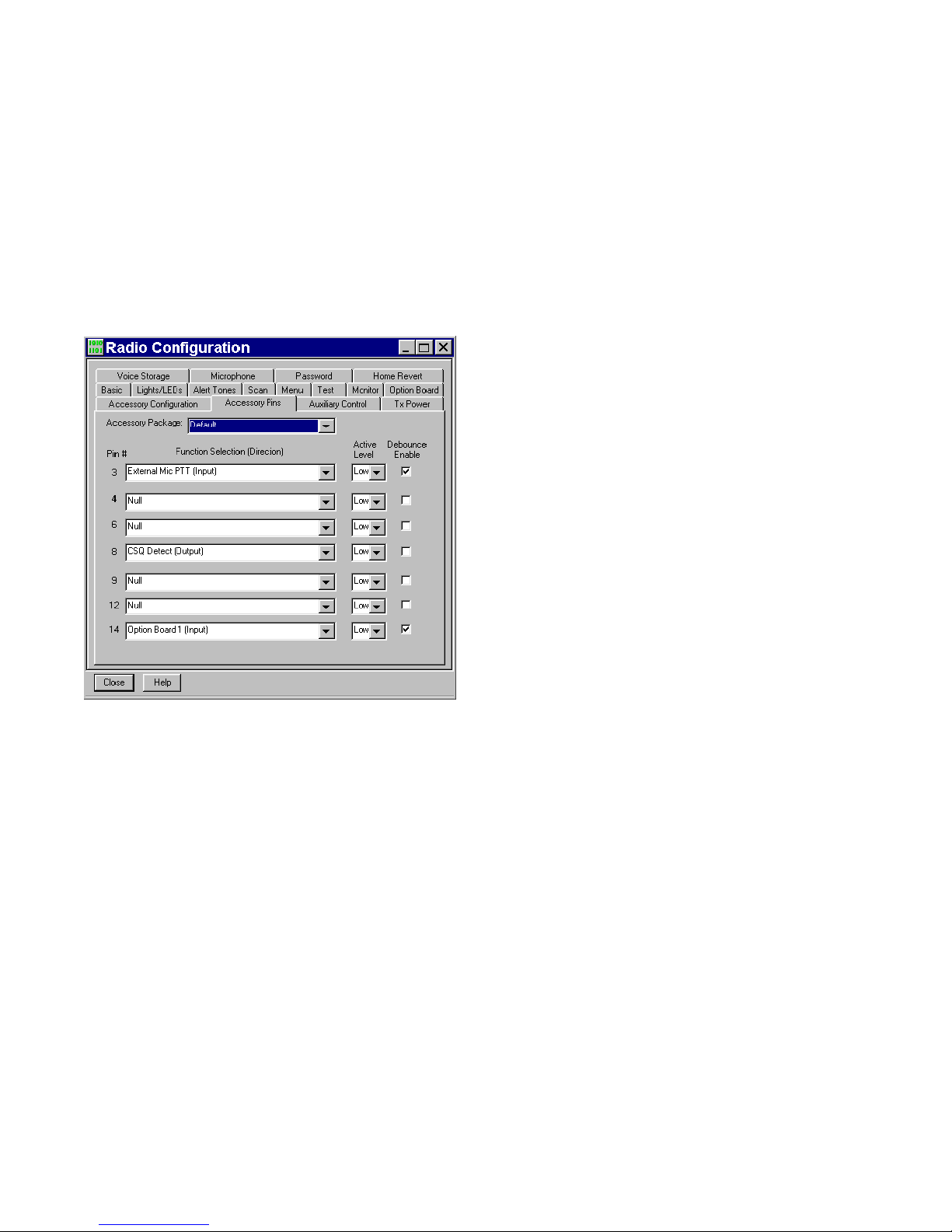
The following two steps apply to the accessory connector and may be skipped by most users.
3. An accessory pin may be used to control the transmit mode of the scrambler between scramble and clear.
This is useful in remote control applications. To enable this feature, one of the radio accessory pins must be
assigned to Option Board 1 (Input) via the CPS programmer.
4. An accessory pin may be used to initiate an emergency ANI. This allows for an external emergency foot
switch or button, and frees-up one of the radio front buttons. To enable this feature, one of the radio
accessory pins must be assigned to Option Board 2 (Input) via the CPS programmer. The switch must be
held in the active state for about 2 seconds before an emergency ANI will be sent.
Note: Accessory pin features do not require any special scrambler programming.
4
Page 5

MOT-TVS-2-PRO-M & MOT-VPU-15-PRO-M
GM-339, GM-340, GM-360, GM-380, GM-399, PRO-7200 Programming Instructions
It is necessary to program the radio before installing the scrambler. This is because the Option Board Feature
of the radio must be enabled in order to program the scrambler using a RIB box and to hear confirmation beeps
from the radio after programming the scrambler.
1. In the Per Radio Miscellaneous Window under the Global Tab, select “Advanced” as the “Option Board Type”
and set the RX Audio (Accessory Connector) to “Filtered Squelched”. Note: The Accessory Connector is the
rear accessory connector, but this setting also affects the audio going to the options connector.
2. For each personality, under the Miscellaneous tab, the “Option Board” must be enabled. Check the Option
Board box for all channels if using a button to control the mode of the scrambler. If doing scrambling on a per
channel basis, then check Option Board Feature only for scrambled channels. It will be necessary to set the
power up state of the scrambler to Scramble for per channel scrambling.
3. For each personality, under the “Audio” tab, the “Voice Pre-emphasis/De-emphasis” must be disabled.
5
Page 6

MOT-TVS-2-PRO-M MOD-1306 & MOT-VPU-15-PRO-M MOD-1306
CDM-1550-LS+, GM-338-LS Programming Instructions
It is necessary to program the radio before installing the scrambler. This is because the Option Board Feature
of the radio must be enabled in order to program the scrambler using a RIB box and to hear confirmation beeps
from the radio after programming the scrambler.
Conventional Programming:
1. In the Radio Configuration Window under the Option Board Tab, select Advanced Option Interface as the
Option Board Type. Do not check the Option Board Configuration Download box.
2. When programming the “Conventional Personality”, Pre-Emphasis may be enabled, but De-Emphasis must
be disabled. This is because De-Emphasis will prevent the scrambler from decoding synchronization data.
Compression should not be used with the scrambler. No, or Low Level expansion may be used. Check the
Option Board Feature box for all channels if using a button to control the mode of the scrambler. If doing
scrambling on a per channel basis, then check Option Board Feature only for scrambled channels. It will be
necessary to set the power up state of the scrambler to Scramble for per channel scrambling.
6
Page 7

LTR Programming:
1. In the LS Trunking Personality window, check the Option Board Feature box for each personality. Check the
Option Board Feature box for all channels if using a button to control the mode of the scrambler. If doing
scrambling on a per channel basis, then check Option Board Feature only for scrambled channels. It will be
necessary to set the power up state of the scrambler to Scramble for per channel scrambling.
2. In the LS Trunking Site window Pre-Emphasis should be enabled, but De-Emphasis must not be enabled.
This is because De-Emphasis will prevent the scrambler from decoding synchronization data. The scrambler
by its very nature performs De-Emphasis function. Compression should not be used with the scrambler.
Expansion should also be disabled.
7
Page 8

The following two steps apply to the accessory connector and may be skipped by most users.
5. An accessory pin may be used to control the transmit mode of the scrambler between scramble and clear.
This is useful in remote control applications. To enable this feature, one of the radio accessory pins must be
assigned to Option Board 1 (Input) via the CPS programmer.
6. An accessory pin may be used to initiate an emergency ANI. This allows for an external emergency foot
switch or button, and frees-up one of the radio front buttons. To enable this feature, one of the radio
accessory pins must be assigned to Option Board 2 (Input) via the CPS programmer. The switch must be
held in the active state for about 2 seconds before an emergency ANI will be sent.
Note: Accessory pin features do not require any special scrambler programming.
8
Page 9

MOT-TVS-2-PRO-M MOD-1331 & MOT-VPU-15-PRO-M MOD-1331 for MPT-1327 Trunking Radios
GM-640, GM-660, GM-1280, MCX-720, MCX-760, MCX-780 Programming Instructions
It is necessary to program the radio before installing the scrambler. This is because the Option Board Feature
of the radio must be enabled in order to program the scrambler using a RIB box and to hear confirmation beeps
from the radio after programming the scrambler.
1. In the Per Radio Parameters Window set the “Option Board Fitted Mode” as “Advanced”.
2. Edit the ‘MPT Personality’. In the “Options” window, check the “Option Board Enable” box. Check Option
Board Enable for all channels if using a button to control the mode of the scrambler. If doing scrambling on a
per channel basis, then check Option Board Enable only for scrambled channels. It will be necessary to set
the power up state of the scrambler to Scramble for per channel scrambling.
9
Page 10

3. If using conventional channels, edit the ‘Conventional Personality Data’. In the “Conventional Personality”
window, check the “Option Board Enable” box. Check Option Board Enable for all channels if using a button
to control the mode of the scrambler. If doing scrambling on a per channel basis, then check Option Board
Enable only for scrambled channels. It will be necessary to set the power up state of the scrambler to
Scramble for per channel scrambling.
10
Page 11

HARDWARE INSTALLATION
Be certain to follow standard anti-static procedures when handling any of Midian’s products.
Radio Firmware: For the mobile radios listed, it is necessary to have radio firmware version R05.00.00 or higher.
If the radio has an older firmware version, it is necessary to upgrade to the newest firmware.
Verifying the firmware version can be done several ways. On most radios, this information is on a label on the
bottom of the radio. For display radios, selecting the SoftwareVer# option from the utility menu will report the
version. Consult Motorola if you cannot determine the firmware version.
Disassembling the Radio:
Additional disassembly instructions are also available in Motorola’s Basic Service Manual.
1. Disconnect power.
2. Remove plastic cover from the radio chassis by prying the sides away and lifting up.
3. Remove the 6 retaining bolts from the metal lid using a Torx™ size 20 screwdriver. Carefully begin removing
the lid. If there is already an option board installed such as a voice storage board, disconnect it by gently
lifting the latch holding the 40-pin flex cable in place.
4. Remove the lid completely. Unscrew the three bolts holding the option board frame to the lid if one is present.
Note: It is not recommended to use the radio for transmitting while disassembled, as some model radios require
the lid to be installed for RF power.
Installing the Scrambler:
1. Insert the 40-pin flex cable into the 40-pin flex connector on the scrambler, making certain it is seated
properly, then close the latch. The silver foil side of the flex should face the edge of the board.
11
Page 12

2. The scrambler is then mounted into the metal lid of the radio using the option board mounting kit. See pictures
below. The mounting kit is ordered from Midian as PRO Option B or from Motorola as RLN4823B. The
mounting kit includes the 40-pin flex cable, the mounting frame and 3 mounting screws.
Reassembling the Radio:
Additional assembly instructions are also available in Motorola’s Basic Service Manual.
1. Once scrambler is installed in the lid, insert the other side of the 40-pin flex cable into the 40-pin flex
connector on the radio’s main board. The shiny side of the flex should face down.
2. Reinstall the metal lid making sure the flex bends toward the back of the radio, otherwise it will be pinched by
the lid. Tighten the screws down in number sequence shown on the lid to 17 in lbs (1.9 NM) torque. Repeat to
verify torque is correct after completing the sequence.
3. Snap on plastic cover.
HARDWARE ALIGNMENT
The MOT-TVS-2-PRO-M series does not require any hardware adjustments, however, when ordering the
scrambler, the radio it will be used in must be specified. The scrambler will come modified by Midian for the
proper model of radio. If for some reason you decide to modify the board because the radio changes, the table
below indicates the parts to change. For example if changing a PRO-M module into a PRO-M MOD-1306; R-3
and R-21 would need to change values.
Scrambler R-1 R-3 R-8 R-12 R-17 R-21 R-23 R-25 R-36 C-33
PRO-M 750 K 300 K N/A 62 K 27 K 100 K 150 K 100 K 0 Ohm N/A
PRO MOD-1306 750 K 750 K N/A 62 K 27 K 91 K 150 K 100 K 0 Ohm N/A
PRO MOD-1331 910 K 910 K 27 K 27 K N/A 47 K 62 K 62 K N/A .01 uf
12
Page 13

PRODUCT PROGRAMMING
Install the MPS programming software if you have not done so already. The MOT-TVS-2-PRO series version 2.8
and higher can be programmed via the Motorola RIB box.
Start the MPS software. From the product selection screen on the MPS software, locate and select MOT-TVS-2PRO or MOT-VPU-15-PRO and the desired model and click OK. The following table shows the proper MPS
selection based upon the model scrambler ordered.
PRO-M (MDC Mobile) MOT-TVS-2-PRO-M or MOT-VPU-15-PRO-M
PRO-M (LTR Mobile) MOT-TVS-2-PRO-M MOD-1306 or MOT-VPU-15-PRO-M MOD-1306
PRO-ME (5-Tone or MPT
Mobile)
MOT-TVS-2-PRO-M, MOT-VPU-15-PRO-M, MOT-TVS-2-PRO-M MOD-1331 or
MOT-VPU-15-PRO-M MOD-1331
Configure the programming software by selecting File->Preferences. Select the appropriate COM port. If using the
RIB box, make certain there is a check mark next to ‘Rib Box Enable’ by clicking on it.
Set the parameters of the MOT-TVS-2-PRO software to fit the application. If any clarifications on a feature are
required, move the mouse cursor over the feature name until the question mark appears and right click, an on-line
help for that feature will be shown. On the radio tab it is necessary to select the proper Radio Model. If the correct
product was selected in the step above then it will be preset in the default file. The following table indicates the
proper Radio Model Selection for the scrambler ordered:
(A) MDC/LTR Mobile MOT-TVS-2-PRO-M, MOT-VPU-15-PRO-M, MOT-TVS-2-PRO-M
MOD-1306 or MOT-VPU-15-PRO-M MOD-1306
(6) 5-Tone or MPT Mobile MOT-TVS-2-PRO-M, MOT-VPU-15-PRO-M, MOT-TVS-2-PRO-M
MOD-1331 or MOT-VPU-15-PRO-M MOD-1331
After entering the parameters, save the file by going to File - Save As. Enter the file name in the File Name block
and click Save. Saving the file will allow for quick and easy reprogramming of units. Turn power on to the radio
and then the RIB. Click ProgramUnit! in the MPS software. You will hear 1-3 beeps from the radio if programmed
successfully.
To read the parameters from the scrambler, Click on ReadUnit!.
13
Page 14

The radio and RIB should be powered down for 3 seconds after reading or programming.
Important Note: Do not attempt to ‘clone’ the scrambler by reading one and then programming another. When
the scrambler is read, the security codes will be read out as zeroes. If another scrambler is then cloned with this
information, the scramblers will be incompatible because they have different security codes. To ensure
scramblers communicate with each other, program them from a saved file.
14
Page 15

OPERATION
Mode Selection: Mode selection means a method of turning the scrambler on and off. In the MOT-TVS-2-PRO
and MOT-VPU-15-PRO series there are two ways of doing this:
Per-Channel Scramble On/Off: To use this feature each channel that is designated as a Scrambled channel
should have the Option Board Feature box enabled in the radio programming software. Channels that are
designated as Clear should NOT have the Option Board feature box enabled. Additionally the Power-Up State in
the MPS software should be set to Scramble. When using Per-Channel Scrambling, a button should NOT be
programmed for Mode Select in the MPS software.
Scramble On/Off Button: To use this feature each channel should have the Option Board Feature box enabled
in the radio programming software. The desired button should be programmed to no function in the radio
programming software. In the MPS software on the Radio tab in the Button Assignment area set the desired
button to “Mode Select”. Pressing and releasing this button will toggle the mode of the scrambler between
scramble and clear. A medium tone followed by a high tone indicates the scrambler is in Scramble mode and a
medium tone followed by a low tone indicates the scrambler is in Clear mode. Also on the Radio tab under the
Miscellaneous section
Code Selection: The TVS-2 or VPU-15 can have up to 4 different codes programmed.
Code Selection Button: To use this feature multiple security codes must be programmed into the TVS-2 or VPU-
15 scrambler. The desired button should be programmed to no function in the radio programming software. In the
MPS software on the Radio tab in the Button Assignment area set the desired button to “Code Select”. Pressing
and releasing this button will step the scrambler to the next security code. The scrambler will emit a number of
beeps corresponding to the code number the scrambler stepped to (i.e. 2 beeps equals security code 2). The
maximum number of codes is 4.
Password: If the password function is enabled the correct password (4 digits using 0-9) must be entered on a
compatible numeric keypad on power up. If the correct password is not entered within 5 attempts the unit will be
disabled. If the radio does not have a compatible numeric keypad do not enable this feature.
Midian’s Kryptic Signaling:
Midian’s TVS-2 and VPU-15 offer the following signaling functions:
ANI: When the PTT button is pressed the scrambler will generate an ANI to be decoded by Midian’s CAD-300 or
DDU-300.
Emergency ANI (ENI): When the Emergency button on the radio is pressed and held for 1 second the scrambler
will key the radio and transmit the ENI to be decoded by Midian’s CAD-300 or DDU-300.
Selective Call: The scrambler can be selectively called from Midian’s CAD-300 or DDU-300. When the scrambler
is called it will generate ringing beeps out the radio’s speaker.
Radio Kill: The scrambler can be disabled and re-enabled from Midian’s CAD-300 or DDU-300. When the
scrambler receives a disable command it will not allow any receive or transmit audio to pass through the
scrambler or for a PTT command to be given to the radio if the PTT path is controlled by the scrambler. When the
scrambler receives an enable command it will resume normal operation.
Spy: The scrambler can be sent a command from Midian’s CAD-300 or DDU-300 to key the radio and transmit
ambient noise from the microphone for 00-90 seconds in 10 second increments. This time is preprogrammed into
the scrambler.
Query: This command sent from Midian’s CAD-300 or DDU-300 will report to the CAD or DDU if the
scrambler/radio is currently on or off.
15
Page 16

TECHNICAL NOTES
Radio Compatibility: Midian has taken the utmost care to ensure the option board integrates into the radio with
minimal impact to the features of the radio. However, some features may not be available in the radio when an
option board is used. If a feature is not available, please contact Midian to see if the feature can be added.
Radio Firmware: Midian recommends having the latest firmware in the radio when installing the scrambler.
However, it should be noted that occasionally firmware updates may cause a conflict with proper option
board/radio communications. This may appear that the scrambler is not working properly, but it is a conflict in the
serial communication between the option board and radio. If this happens it will be necessary to go back to the
original firmware revision.
Please note that firmware versions between the EMEA region and the Asia and America regions might be
different.
Scan: Midian strongly recommends not using the radio’s Scan function when using voice scramblers. First of all
synchronization packets will most likely not be decoded by the receiving radios, as the receiving radio may be
looking at a different channel when sync is transmitted. Additionally if using a combination of scrambling on a perchannel basis and a mode select button to control the state of the scrambler, when the scan function is used the
radio will ignore the button. This is best resolved by using per-channel scrambling OR a mode select button, but
not both. If using scan and a mode-select button the Option Board Feature box in the radio programming section
must be enabled on all channels.
Known Issues: The "Enable Wired PTT" function on the "Radio" screen of the MPS UP is obsolete. This box
should never be checked. The "Combo (press & hold)" and "Emerg (press & hold)" are not supported on the P1,
P2, and P3 buttons when using Enhanced Integration. Use of the System Scan feature of the radio has been
known to cause a problem whereby the transmitter stays on the air 3 seconds after PTT is released. Checking the
"Reserved Function" box on the "Advanced" screen of the MPS UP works around this radio problem.
Accessory Pin Features: Upon power-up, the radio does not always report the state of the accessory pins to
the option board. It may be necessary to toggle the state of these inputs once after power-up to ensure correct
operation.
Option Board Feature: Enabling the option board feature tells the radio to report events such as button press,
PTT press, carrier detect, etc. to the option board. This feature enables communication between the option board
and the radio.
When controlling the scrambler with a radio button, it is absolutely required to enable this feature on all channels.
For scrambling on a per channel basis only enable the option board on scrambled channels and the power up
mode of the scrambler should be Scramble. On display models, the following icon appears on the LCD when
option board mode is on:
Known Issues: The radio must be off for a full 3 seconds prior to being turned on or the scrambler cannot reset
properly resulting in malfunction. The "Enable LCD Message" option in the MPS UP should not be enabled due to
problems in the radio. If problems are experienced when reading the scrambler from the RIB box, use the MPS
cable.
16
Page 17

MIDIAN ELECTRONICS, INC.
2302 East 22
nd
Street
Tucson, Arizona 85713 USA
Toll-Free: 1-800-MIDIANS
Main: 520-884-7981
E-mail: sales@midians.com
Web: www.midians.com
MIDIAN CONTACT INFORMATION
17
Page 18

- This page intentionally left blank -
Page 19

1
1
2
2
3
3
4
4
5
5
6
6
D D
C C
B B
A A
OSC2
36
TCMP
33
VDD
38
VPP
43
SS
32
B3
11
D7
34
OSC1
37
B0
8
B1
9
A5
2
A6
1
A7
44
A43A34A25A16A0
7
C4
21
C5
20
C3
23
C0
26
C1
25
C2
24
C6
19
C7
18
B4
12
B7
15
B6
14
GND
17
RES
41
B2
10
TCAP
35
IRQ
42
B5
13
SCK
31
MOSI
30
MISO
29
RDI
27
TDO
28
NC1
16
NC2
22
NC339NC4
40
68705FPHS
IC1
10K
R32
PAD1
PAD2
Vddd
*
C3
*
C33
.01u
C2
*
R39
D
C
B
10K
R35
Vddd
*
R40
0R
R33
3 2
1
*
IC8
*
R9
VdddVddd
100p
C32
0R
R6
300K
R3
39p
C6
1.8M
R4
4.7K
R5
.0068u
C7
-
+
2
3
1
LMV324
IC7:1
-
+
6
5
7
LMV324
IC7:2
-
+
9
10
8
LMV324
IC7:3
-
+
13
12
14
LMV324
IC7:4
A
X0
X1
X
4053
IC9:1
B
Y1
Y0
Y
4053
IC9:2
C
Z
Z0
Z1
E
VCC
VEE
GND
4053
IC9:3
39p
C5
1.2M
R2
750K
R1
0R
R36
27K
R17
*
R8
.0068u
C10
.0068u
C11
8.2K
R18
56K
R19
36K
R20
.001u
C12
1.2M
R22
100K
R21
.1u
C19
Vddd
.1u
C9
18K
R10
BSS
Q1
100K
R11
62K
R12
36K
R13
-
+
2
3
1
TLV2375
IC6:1
-
+
6
5
7
TLV2375
IC6:2
-
+
11
12
10
TLV2375
IC6:3
-
+
15
14
16
TLV2375
IC6:4
3/4SHDN
9
1/2SHDN
8
TLV2375
IC6:6
OSC1
18
OSC2
17
A4
3
A0
19
A1
20
MCLR
4
VDD
15
VDD
16
VSS5VSS
6
B6
13
B7
14
B18B29B3
10
B4
11
B0
7
B5
12
A2
1
A3
2
16F716
IC2
Vddd
36K
R16
10K1%
R14
10K1%
R15
100p
C31
39p
C13
123
4
5
6
7
8
LTC1069
IC5
Vddd
.1u
C16
+
4.7u
C30
.1u
C14
.001u
C15
22p
C4
36K
R24
150K
R23
100K
R25
0R
R31
22p
C27
*
C8
10K
R26
0R
R30
22p
C23
82p
C22
39p
C21
150p
C20
470p
C24
VS
1
GND
2
OUT
3
TRG
4
THS
5
MIC555
IC4
4.7K
R28
1K Ohms
RC18
Vddd
3.58 MHz.
Y1
4.7M
R29 22p
C26
22p
C25
CS
1
SCLK
2
SI
3
SO
4
VCC
8
NC1
7
NC2
6
GND
5
9346
IC3
100K
R7
.1u
C17
Vddd
10K
R38
0R
R37
Vddd
RESET
*
R630
*
R625
*
R34
100p
C615
SJ2
SJ4
SHDN
7
V+
4
CLK
8
IN2OUT
5
COM1OS6V-
3
7427
IC10
Vddd
4.7K
R41
.01u
C34
CP
CJS
1999-11-01 DML
2014-05-09
H-2
1 of 2
7313
MIDIAN ELECTRONICS, INC.
DATE:
DESIGN:
DWN BY:
REV:
APPR
COPYRIGHT ©
REV
SHEET
PROJECT NUMBER
DOCUMENT NAME
SCHEMATIC
2012
MOT-TVS-2/MOT-VPU-15
PRO-M
VDDD
GND
RDY
PTT
MISO
DATA2
DATA1
OPT-ENACLK2
CLK1
TX IN
RX IN
DISC IN
TX OUT
RX OUT
A2
A1
D2
D1
*
C613
PIC201
PIC202
COC2
PIC301
PIC302
COC3
PIC401 PIC402
COC4
PIC501 PIC502
COC5
PIC601 PIC602
COC6
PIC701
PIC702
COC7
PIC801 PIC802
COC8
PIC901 PIC902
COC9
PIC1001PIC1002
COC10
PIC1101PIC1102
COC11
PIC1201
PIC1202
COC12
PIC1301
PIC1302
COC13
PIC1401
PIC1402
COC14
PIC1501
PIC1502
COC15
PIC1601
PIC1602
COC16
PIC1701
PIC1702
COC17
PIC1901
PIC1902
COC19
PIC2001PIC2002
COC20
PIC2101 PIC2102
COC21
PIC2201 PIC2202
COC22
PIC2301
PIC2302
COC23
PIC2401
PIC2402
COC24
PIC2501
PIC2502
COC25
PIC2601
PIC2602
COC26
PIC2701
PIC2702
COC27
PIC3001
PIC3002
COC30
PIC3101
PIC3102
COC31
PIC3201
PIC3202
COC32
PIC3301
PIC3302
COC33
PIC3401
PIC3402
COC34
PIC61301
PIC61302
COC613
PIC61501
PIC61502
COC615
PIIC101
PIIC102
PIIC103 PIIC104 PIIC105 PIIC106 PIIC107
PIIC108
PIIC109
PIIC1010
PIIC1011
PIIC1012
PIIC1013
PIIC1014
PIIC1015
PIIC1016
PIIC1017
PIIC1018
PIIC1019
PIIC1020
PIIC1021
PIIC1022
PIIC1023
PIIC1024
PIIC1025
PIIC1026
PIIC1027
PIIC1028
PIIC1029
PIIC1030
PIIC1031
PIIC1032
PIIC1033
PIIC1034
PIIC1035
PIIC1036
PIIC1037
PIIC1038 PIIC1039PIIC1040
PIIC1041
PIIC1042PIIC1043
PIIC1044
COIC1
PIIC201
PIIC202
PIIC203
PIIC204
PIIC205 PIIC206 PIIC207
PIIC208 PIIC209
PIIC2010PIIC2011 PIIC2012PIIC2013
PIIC2014
PIIC2015
PIIC2016
PIIC2017
PIIC2018
PIIC2019
PIIC2020
COIC2
PIIC301
PIIC302
PIIC303
PIIC304
PIIC305
PIIC306
PIIC307
PIIC308
COIC3
PIIC401
PIIC402
PIIC403
PIIC404
PIIC405
COIC4
PIIC501
PIIC502
PIIC503
PIIC504
PIIC505
PIIC506 PIIC507
PIIC508
COIC5
PIIC601
PIIC602
PIIC603
COIC6:1
PIIC605
PIIC606
PIIC607
COIC6:2
PIIC6010
PIIC6011
PIIC6012
COIC6:3
PIIC6014
PIIC6015
PIIC6016
COIC6:4
PIIC608
PIIC609
COIC6:6
PIIC701
PIIC702
PIIC703
COIC7:1
PIIC705
PIIC706
PIIC707
COIC7:2
PIIC708
PIIC709
PIIC7010
COIC7:3
PIIC7012
PIIC7013
PIIC7014
COIC7:4
PIIC801
PIIC802PIIC803
COIC8
PIIC9011
PIIC9012
PIIC9013
PIIC9014
COIC9:1
PIIC901
PIIC902
PIIC9010
PIIC9015
COIC9:2
PIIC903
PIIC904
PIIC905
PIIC906 PIIC907 PIIC908
PIIC909
PIIC9016
COIC9:3
PIIC1001
PIIC1002
PIIC1003
PIIC1004
PIIC1005
PIIC1006
PIIC1007PIIC1008
COIC10
PIPAD101
COPAD1
PIPAD201
COPAD2
PIPAD301
COPAD3
PIPAD401
COPAD4
PIPAD501
COPAD5
PIQ10D
PIQ10G
PIQ10S
COQ1
PIR101PIR102
COR1
PIR201 PIR202
COR2
PIR301PIR302
COR3
PIR401
PIR402
COR4
PIR501PIR502
COR5
PIR601
PIR602
COR6
PIR701
PIR702
COR7
PIR801
PIR802
COR8
PIR901
PIR902
COR9
PIR1001
PIR1002
COR10
PIR1101
PIR1102
COR11
PIR1201PIR1202
COR12
PIR1301PIR1302
COR13
PIR1401
PIR1402
COR14
PIR1501
PIR1502
COR15
PIR1601
PIR1602
COR16
PIR1701
PIR1702
COR17
PIR1801
PIR1802
COR18
PIR1901PIR1902
COR19
PIR2001 PIR2002
COR20
PIR2101
PIR2102
COR21
PIR2201 PIR2202
COR22
PIR2301PIR2302
COR23
PIR2401 PIR2402
COR24
PIR2501PIR2502
COR25
PIR2601 PIR2602
COR26
PIR2801
PIR2802
COR28
PIR2901
PIR2902
COR29
PIR3001PIR3002
COR30
PIR3101PIR3102
COR31
PIR3201
PIR3202
COR32
PIR3301
PIR3302
COR33
PIR3401
PIR3402
COR34
PIR3501
PIR3502
COR35
PIR3601PIR3602
COR36
PIR3701 PIR3702
COR37
PIR3801
PIR3802
COR38
PIR3901PIR3902
COR39
PIR4001PIR4002
COR40
PIR4101 PIR4102
COR41
PIR62501 PIR62502
COR625
PIR63001
PIR63002
COR630
PIRC1801
PIRC1802
CORC18
PISJ201
PISJ202
COSJ2
PISJ401
PISJ402
COSJ4
COtb0sch1
PIY101
PIY102
COY1
Page 20

1
1
2
2
3
3
4
4
5
5
6
6
D D
C C
B B
A A
CP
CJS
1999-11-01 DML
2014-05-09
H-2
2 of 2
7313
MIDIAN ELECTRONICS, INC.
DATE:
DESIGN:
DWN BY:
REV:
APPR
COPYRIGHT ©
REV
SHEET
PROJECT NUMBER
DOCUMENT NAME
SCHEMATIC
2012
MOT-TVS-2/MOT-VPU-15
PRO-M
*
D601*D602*D603*D604*D605*D606
*
R618*R619
*
R620
*
R621
*
R622
*
R623
*
Q603
*
Q602
*
R633
*
R646
*
R632
*
R648
*
C616
*
R647
J602:18
J601:3
*
R649
Vddd SW_B+
SW_B+
SJ1
TP2
100p
C610
Vddd
*
R629
*
R638
*
R631
*
C611
*
C612
*
R601*R602
*
R603
*
R607
*
R604
*
R608
*
R605
*
R609
*
R606
*
R610
1K
R611
1K
R612
*
R613
*
C609
-
+
4
3
1
*
25
IC602
Vddd Vddd
Vddd Vddd
ROW1
ROW2 ROW3 ROW4 ROW5
COL1
COL2 COL3 COL4 COL5
411
LMV324
IC7:5
413
TLV2375
IC6:5
Vddd Vddd
SJ6 SJ7
*
Q601
1
B4
1
B5
1
B6
1
B7
1
B8
1
B9
1
B10
1
B11
1
B12
1
B13
1
B14
1
B15
1
B16
1
B17
1
B18
1
B19
1
B20
1
B21
ROW3
ROW4
ROW5
COL5
COL1 COL2 COL3
ROW1
COL1
COL2
COL3
ROW2
COL1
COL2
COL3
ROW3
COL1
COL2
COL3
ROW4
COL1
COL2
COL3
ROW5
KEY_INTRP
LED ENA
RW1RW2
A02 A01
LCD SEL
VDDD
GND
LED PWR
100p
C617
EXT MIC
PIB401 PIB402
PIB403
COB4
PIB501 PIB502 PIB503
COB5
PIB601 PIB602 PIB603
COB6
PIB701 PIB702
PIB703
COB7
PIB801 PIB802 PIB803
COB8
PIB901 PIB902 PIB903
COB9
PIB1001 PIB1002 PIB1003
COB10
PIB1101 PIB1102 PIB1103
COB11
PIB1201 PIB1202 PIB1203
COB12
PIB1301 PIB1302 PIB1303
COB13
PIB1401 PIB1402 PIB1403
COB14
PIB1501 PIB1502 PIB1503
COB15
PIB1601 PIB1602 PIB1603
COB16
PIB1701 PIB1702 PIB1703
COB17
PIB1801 PIB1802 PIB1803
COB18
PIB1901 PIB1902 PIB1903
COB19
PIB2001 PIB2002 PIB2003
COB20
PIB2101 PIB2102 PIB2103
COB21
PIC60901PIC60902
COC609
PIC61001
PIC61002
COC610
PIC61101
PIC61102
COC611
PIC61201
PIC61202
COC612
PIC61601
PIC61602
COC616
PIC61701
PIC61702
COC617
PID60101
PID60102
COD601
PID60201
PID60202
COD602
PID60301
PID60302
COD603
PID60401
PID60402
COD604
PID60501
PID60502
COD605
PID60601
PID60602
COD606
PIIC604
PIIC6013
COIC6:5
PIIC704
PIIC7011
COIC7:5
PIIC60201
PIIC60202
PIIC60203
PIIC60204
PIIC60205
COIC602
PIJ60103
COJ601:3
PIJ602018
COJ602:18
PIQ6010B
PIQ6010C
PIQ6010E
COQ601
PIQ6020B
PIQ6020C
PIQ6020E
COQ602
PIQ6030B
PIQ6030C
PIQ6030E
COQ603
PIR60101
PIR60102
COR601
PIR60201
PIR60202
COR602
PIR60301 PIR60302
COR603
PIR60401PIR60402
COR604
PIR60501 PIR60502
COR605
PIR60601PIR60602
COR606
PIR60701 PIR60702
COR607
PIR60801PIR60802
COR608
PIR60901 PIR60902
COR609
PIR61001PIR61002
COR610
PIR61101
PIR61102
COR611
PIR61201
PIR61202
COR612
PIR61301PIR61302
COR613
PIR61801
PIR61802
COR618
PIR61901
PIR61902
COR619
PIR62001
PIR62002
COR620
PIR62101
PIR62102
COR621
PIR62201
PIR62202
COR622
PIR62301
PIR62302
COR623
PIR62901
PIR62902
COR629
PIR63101
PIR63102
COR631
PIR63201
PIR63202
COR632
PIR63301
PIR63302
COR633
PIR63801
PIR63802
COR638
PIR64601
PIR64602
COR646
PIR64701 PIR64702
COR647
PIR64801
PIR64802
COR648
PIR64901PIR64902
COR649
PISJ101
PISJ102
COSJ1
PISJ601
PISJ602
COSJ6
PISJ701PISJ702
COSJ7
COtb0sch2
PITP201
COTP2
Page 21

PAC202
PAC201
COC2
PAC301
PAC302
COC3
PAC401
PAC402
COC4
PAC501
PAC502
COC5
PAC601
PAC602
COC6
PAC701
PAC702
COC7
PAC801
PAC802
COC8
PAC901 PAC902
COC9
PAC1002
PAC1001
COC10
PAC1101
PAC1102
COC11
PAC1202
PAC1201
COC12
PAC1301
PAC1302
COC13
PAC1401
PAC1402
COC14
PAC1501
PAC1502
COC15
PAC1602
PAC1601
COC16
PAC1701
PAC1702
COC17
PAC1902 PAC1901
COC19
PAC2002
PAC2001
COC20
PAC2101
PAC2102
COC21
PAC2201
PAC2202
COC22
PAC2302
PAC2301
COC23
PAC2402
PAC2401
COC24
PAC2501
PAC2502
COC25
PAC2601
PAC2602
COC26
PAC2702
PAC2701
COC27
PAC3001 PAC3002
COC30
PAC3101
PAC3102
COC31
PAC3202
PAC3201
COC32
PAC3302
PAC3301
COC33
PAC3401
PAC3402
COC34
PAC60902
PAC60901
COC609
PAC61002
PAC61001
COC610
PAC61102
PAC61101
COC611
PAC61202
PAC61201
COC612
PAC61301
PAC61302
COC613
PAC61502PAC61501
COC615
PAC61601
PAC61602
COC616
PAC61701
PAC61702
COC617
PAIC1044 PAIC1043 PAIC1042
PAIC1041
PAIC1040 PAIC1039 PAIC1038 PAIC1037PAIC1036 PAIC1035 PAIC1034
PAIC1033
PAIC1032
PAIC1031
PAIC1030
PAIC1029
PAIC1028
PAIC1027
PAIC1026
PAIC1025
PAIC1024
PAIC1023
PAIC1022PAIC1021PAIC1020PAIC1019PAIC1018PAIC1017PAIC1016
PAIC1015
PAIC1014PAIC1013PAIC1012
PAIC1011
PAIC1010
PAIC109
PAIC108
PAIC107
PAIC106
PAIC105
PAIC104
PAIC103
PAIC102
PAIC101
COIC1
PAIC201
PAIC202PAIC203
PAIC204
PAIC205PAIC206 PAIC207PAIC208PAIC209
PAIC2010
PAIC2020
PAIC2019PAIC2018
PAIC2017
PAIC2016PAIC2015 PAIC2014PAIC2013PAIC2012 PAIC2011
COIC2
PAIC301
PAIC302
PAIC303
PAIC304
PAIC308
PAIC307
PAIC306
PAIC305
COIC3
PAIC404
PAIC405 PAIC401
PAIC402
PAIC403
COIC4
PAIC505
PAIC506
PAIC507
PAIC508
PAIC504
PAIC503
PAIC502
PAIC501
COIC5
PAIC601
PAIC602
PAIC603
PAIC604
PAIC605
PAIC606
PAIC607
PAIC608
PAIC6016
PAIC6015
PAIC6014
PAIC6013
PAIC6012
PAIC6011
PAIC6010
PAIC609
COIC6
PAIC701
PAIC702
PAIC703
PAIC704
PAIC705
PAIC706
PAIC707
PAIC7014
PAIC7013
PAIC7012
PAIC7011
PAIC7010
PAIC709
PAIC708
COIC7
PAIC801
PAIC802
PAIC803
COIC8
PAIC909
PAIC9010
PAIC9011
PAIC9012
PAIC9013
PAIC9014
PAIC9015
PAIC9016
PAIC908
PAIC907
PAIC906
PAIC905
PAIC904
PAIC903
PAIC902
PAIC901
COIC9
PAIC1001PAIC1002PAIC1003PAIC1004
PAIC1005PAIC1006PAIC1007PAIC1008
COIC10
PAIC60203
PAIC60202
PAIC60201PAIC60205
PAIC60204
COIC602
PAJ60100
PAJ601040
PAJ601038
PAJ601036
PAJ601034
PAJ601032
PAJ601030
PAJ601028
PAJ601026
PAJ601024
PAJ601022
PAJ601020
PAJ601018
PAJ601016
PAJ601014
PAJ601012
PAJ601010
PAJ60108
PAJ60106
PAJ60104
PAJ60102
PAJ601039
PAJ601037
PAJ601035
PAJ601033
PAJ601031
PAJ601029
PAJ601027
PAJ601025
PAJ601023
PAJ601021
PAJ601019
PAJ601017
PAJ601015
PAJ601013
PAJ601011
PAJ60109
PAJ60107
PAJ60105
PAJ60103
PAJ60101
COJ601
PAJ6020A
PAJ6020B
PAJ60201
PAJ60202
PAJ60203
PAJ60204
PAJ60205
PAJ60206
PAJ60207
PAJ60208
PAJ60209
PAJ602010
PAJ602011
PAJ602012
PAJ602013
PAJ602014
PAJ602015
PAJ602016
PAJ602017
PAJ602018
COJ602
PAPAD101
COPAD1
PAPAD201
COPAD2
PAPAD301
COPAD3
PAPAD401
COPAD4
PAPAD501
COPAD5
PAQ10S
PAQ10D
PAQ10G
COQ1
PAQ6010E
PAQ6010C
PAQ6010B
COQ601
PAQ6020E
PAQ6020C
PAQ6020B
COQ602
PAQ6030B
PAQ6030C
PAQ6030E
COQ603
PAR101
PAR102
COR1
PAR202
PAR201
COR2
PAR302PAR301
COR3
PAR402
PAR401
COR4
PAR501
PAR502
COR5
PAR602
PAR601
COR6
PAR702
PAR701
COR7
PAR801
PAR802
COR8
PAR902
PAR901
COR9
PAR1002PAR1001
COR10
PAR1102
PAR1101
COR11
PAR1201
PAR1202
COR12
PAR1301
PAR1302
COR13
PAR1401PAR1402
COR14
PAR1502
PAR1501
COR15
PAR1602
PAR1601
COR16
PAR1702
PAR1701
COR17
PAR1801
PAR1802
COR18
PAR1902
PAR1901
COR19
PAR2002
PAR2001
COR20
PAR2102
PAR2101
COR21
PAR2201PAR2202
COR22
PAR2302
PAR2301
COR23
PAR2402
PAR2401
COR24
PAR2501
PAR2502
COR25
PAR2602
PAR2601
COR26
PAR2802
PAR2801
COR28
PAR2902 PAR2901
COR29
PAR3002
PAR3001
COR30
PAR3101
PAR3102
COR31
PAR3202
PAR3201
COR32
PAR3301
PAR3302
COR33
PAR3402
PAR3401
COR34
PAR3502
PAR3501
COR35
PAR3601
PAR3602
COR36
PAR3701 PAR3702
COR37
PAR3801
PAR3802
COR38
PAR3901
PAR3902
COR39
PAR4001
PAR4002
COR40
PAR4102PAR4101
COR41
PAR60102
PAR60101
COR601
PAR60201
PAR60202
COR602
PAR60302
PAR60301
COR603
PAR60401
PAR60402
COR604
PAR60502
PAR60501
COR605
PAR60601
PAR60602
COR606
PAR60702
PAR60701
COR607
PAR60801
PAR60802
COR608
PAR60902
PAR60901
COR609
PAR61001
PAR61002
COR610
PAR61102PAR61101
COR611
PAR61201 PAR61202
COR612
PAR61301
PAR61302
COR613
PAR61801
PAR61802
COR618
PAR61901
PAR61902
COR619
PAR62002 PAR62001
COR620
PAR62102PAR62101
COR621
PAR62201PAR62202
COR622
PAR62302
PAR62301
COR623
PAR62502
PAR62501
COR625
PAR62901
PAR62902
COR629
PAR63001
PAR63002
COR630
PAR63101 PAR63102
COR631
PAR63202
PAR63201
COR632
PAR63301
PAR63302
COR633
PAR63802
PAR63801
COR638
PAR63902
PAR63901
COR639
PAR64101
PAR64102
COR641
PAR64302
PAR64301
COR643
PAR64501
PAR64502
COR645
PAR64602
PAR64601
COR646
PAR64702
PAR64701
COR647
PAR64801 PAR64802
COR648
PAR64901 PAR64902
COR649
PARC1801
PARC1802
CORC18
PASJ101
PASJ102
COSJ1
PASJ201 PASJ202
COSJ2
PASJ302
PASJ301
COSJ3
PASJ402PASJ401
COSJ4
PASJ501
PASJ502
COSJ5
PASJ601
PASJ602
COSJ6
PASJ702
PASJ701
COSJ7
COtb0sch1
PATP201
COTP2
PAVO201
PAVO202
PAVO200
PAVO2040
PAVO2038
PAVO2036
PAVO2034
PAVO2032
PAVO2030
PAVO2028
PAVO2026
PAVO2024
PAVO2022
PAVO2020
PAVO2018
PAVO2016
PAVO2014
PAVO2012
PAVO2010
PAVO208
PAVO206
PAVO204
PAVO2039
PAVO2037
PAVO2035
PAVO2033
PAVO2031
PAVO2029
PAVO2027
PAVO2025
PAVO2023
PAVO2021
PAVO2019
PAVO2017
PAVO2015
PAVO2013
PAVO2011
PAVO209
PAVO207
PAVO205
PAVO203
PAVO20E
PAVO20C
PAVO20B
PAVO2041
PAVO2042PAVO2043PAVO2044
PAVO20A
PAVO20S
PAVO20D
PAVO20G
COVO2
PAY101
PAY102
PAY103
COY1
Page 22

PAB401
PAB402
PAB403
COB4
PAB503
PAB502
PAB501
COB5
PAB601
PAB602
PAB603
COB6
PAB703
PAB702
PAB701
COB7
PAB801
PAB802
PAB803
COB8
PAB903
PAB902
PAB901
COB9
PAB1001
PAB1002
PAB1003
COB10
PAB1103
PAB1102
PAB1101
COB11
PAB1201
PAB1202
PAB1203
COB12
PAB1303
PAB1302
PAB1301
COB13
PAB1401
PAB1402
PAB1403
COB14
PAB1503
PAB1502
PAB1501
COB15
PAB1601
PAB1602
PAB1603
COB16
PAB1703
PAB1702
PAB1701
COB17
PAB1801
PAB1802PAB1803
COB18
PAB1903
PAB1902
PAB1901
COB19
PAB2001
PAB2002PAB2003
COB20
PAB2103
PAB2102
PAB2101
COB21
PAD60102 PAD60101
COD601
PAD60201PAD60202
COD602
PAD60302 PAD60301
COD603
PAD60402
PAD60401
COD604
PAD60501
PAD60502
COD605
PAD60601PAD60602
COD606
COtb0sch2
PAVO101
PAVO102
PAVO103
COVO1
 Loading...