

Page 1

Model
DDU-300
DISPATCH DISPLAY UNIT
INSTRUCTION MANUAL
Model Features
• 10 entry ANI r ec all memory
• 137 entry alias database
• Auto-mute leading ANI
• Alternat e function as a repeater access controller
MANUAL REVISION: 2006.02.22
COVERS PRODUCT SOFTWARE VE RS ION(S):
2.0
WITH DECODER VERS ION(S):
3.5
_____ _____ _____ _____
_____ _____ _____ _____
• Decodes Midian’s TVS - 2 K r y ptic 4-digit ANI’s
• 11 status messages includi ng emergency
• Easy to read backlit LCD display
• Serial printer l ogging (w/optional cable)
COPYRIGHT
DDU-300
MIDIAN ELECTRONICS, INC. 2302 East 22nd Street Tucso n, Arizona 85713
To O rder: 1-800-MIDI ANS Telep hone: (520) 884- 7981 Fax: (520) 884-0422
2002-2004 MIDIAN ELECTRONICS I NC. ALL RIGHTS RESERVED.
Page 2

1 SPECIFICATIONS
Voltage/Current
Operating V oltage (nom inal) ...............................12 VDC
Operating V oltage (m in-max) .........................12-15 VDC
Operating Current (standby @12 VDC) ................100 m A
Operating Current (peak @15 VDC).....................500 mA
Inputs
Input Level (RX)....................................100-3000 mV p-p
Input Impedance (RX)...........................................> 10kΩ
Outputs
Output Level (TX, unloaded) .................150-2500 mV p-p
Output Impedance (TX)........................... 27kΩ if JU4 cut
Speaker Audio O utput................................... 1 W into 8Ω
WARRANTY
Midian Electronics, Inc., warrants this product to be
free from defects in material and workmanship for
two years from date of shipment. If such malfunction
occurs, it will be repaired or replaced (at our option)
without charge f or m ateri als or labor i f returned to the
factory. This warranty does not apply to any parts
damaged due to improper use--including accident,
neglect, unreasonabl e use, and im pr oper i nstall at ion- or to unauthorized alterat ions or modifi cations of the
equipment . It does not ex tend to damage i ncurred by
natural causes such as light ning, f ire, f loods, or other
such catastrophes, nor to damage caused by
environmental extremes, such as power surges
and/or transients. It does not extend to
micr oprocessors, i f i t i s determ i ned by M idi an t hat t he
fail ure of a m icro is due to stat ic dam age, appli cati on
of improper voltages to the unit, or other problems not
related to cir c uit design. In such case or i n the case of
a desire to updat e the micro t o a diff erent versi on of
software, such request must be specified in writing,
and there will be a charge agreed upon by both
parties.
This product is warranted to meet published
specifications and to operate as specified only when
properly installed in radio equipment which complies
with U.S. F CC specifi cations and the applicabl e radio
manufacturer's specifications. Midian Electronics is
not responsible for any operational problems caused
by system design, outside interference, or improper
installation.
Mechanical
Dimensions: ...................................2⅞"H x 6½W x 8¾"L
Operating Temp..............................................0° to 50° C
Decode Format
MIdian’s TVS-2 Kryptic format (4-digit)
Other
ANI Recall Stack Size .................................................10
Alias Database Si z e ..................................................137
Equipment for repair can be returned to the factory
without prior written authorization. A brief letter
describing the nat ure of t he def ect should be i ncl uded
with the merchandise. Repair by other than Midian
Electronics, Inc., will void this warranty. In-warranty
merchandise must be shipped, freight prepaid, to
Midian Electronics. Midian Electronics will return,
freight prepaid via UPS ground, the repaired or
replaced equipment to purchaser, within the United
States. Out-of-warranty repairs will be billed at the
rate of $60 per hour, plus replac ement parts.
This warranty appl ies to the original purchaser of the
equipment only. M idi an Elect ronics is not l iabl e under
this warranty, or any impl ied warranty, f or loss of use
or for other consequential loss or damage
experienced by the purchaser. Some states do not
permit the exclusion or limitation of implied warranties
or consequential damages. This warranty provides
special legal rights, and the purchaser may have
other rights that v ar y from state to state.
Copyright Notice
The information in this manual and any software in
this product remain the property of MIDIAN
ELECTRONICS, INC. Reproduction, duplication, or
disclosure is not permitted without the prior written
consent of MIDIAN ELECTRONICS, INC.
DDU-300 Manual Rev. 2006.02.22
Page 3

MIDIAN ELECTRONICS INCORPORATED PAGE 3
TABLE OF CONTENTS
1 SPECIFICATIONS ........................................................................................................................... 2
2 OVERVIEW................................................................................................................................ 4
3 INSTALLATION INSTRUCTIONS............................................................................................. 4
3.1 RADIO INTERFACE ............................................................................................................................. 4
3.2 JUMPER SETTINGS ............................................................................................................................5
3.3 ADJUSTMENTS................................................................................................................................... 5
3.4 CONFIGURATION SETTINGS................................................................................................................5
4 BASIC OPERATION.................................................................................................................. 5
4.1 DISPLAY MODE.................................................................................................................................. 5
4.2 MENU MODE ..................................................................................................................................... 6
4.3 USER DATABASE ............................................................................................................................... 7
4.4 MISCELLANEOUS FEATURES............................................................................................................... 7
5 MENU SYSTEM......................................................................................................................... 8
5.1 CALL COMMAND ............................................................................................................................... 8
5.2 ACTIONS MENU............................................................................................................................... 8
5.3 LOCK OR UNLOCK COMMAND .........................................................................................................8
5.4 USERS MENU................................................................................................................................... 8
5.5 ADMIN MENU.................................................................................................................................... 9
5.6 SETUP MENU................................................................................................................................... 9
6 SYSTEM ERROR MESSAGES................................................................................................ 14
7 MENU SYSTEM MAP.............................................................................................................. 1 5
SCHEMATIC
PICTORIAL
DDU-300 Manual Rev. 2006.02.22
Page 4

PAGE 4 MIDIAN ELECTRONICS INCORPORATED
AUDIO OUTPUT/TX OUT (P1-4) [Green]
2 OVERVIEW
The DDU provides the optimal ANI display decoder
solution for small and medium sized radio systems
such as those used by tax i fl eets, polic e department s,
constructi on c r ews, etc.
The last 10 ANI's received can be reviewed at any
time. It can store up to 137 aliases in its user
database. The user f riendly menu system m akes it as
easy to use as a cell phone. Additional features
include emergency status display and the ability to
automaticall y mute incoming l eading ANI's.
In additi on to the decode f eat ures, the DDU-300 offers
fleet managem ent funct ions includi ng selectiv e calling
of unit s, over the ai r reprogramm ing (OTAR), and the
ability to disable units remotely.
3 INSTALLATION INSTRUCTIONS
Installation Note: Midian products ut ilize CMOS integrated
circuits, which are susceptible to damage from high static
charges. Be sure to follow standard antistatic procedures
when handling, including using grounded workstations and
soldering irons and wearing groundi ng br acelets.
3.1 RADIO INTERFACE
Radio Interf ace connector P1 is an 8-pin
RJ-45 styl e connect or i n the center of t he
back panel.
+V IN (P1- 5) [ Red]
The DDU can be powered either by an optional wall
transform er or by t he radio power supply. Connect thi s
wire to the radi o power source prov ided it is between
12 and 15 VDC.
If using a wall transformer, m ake sure the voltage i s
between 12 and 15 VDC and the current rating is at
least 800mA. Also, be certain that positive is
connected to the inside ring.
GROUND (P1-6) [Black]
Connect to radi o ground.
AUDIO INPUT/RX IN (P1-8) [Blue]
Connect to a poi nt in t he radio where receiv e audio i s
present at a constant lev el. If using PL or CTCSS, be
sure to connect to a poi nt after t he CTCSS high pass
fil ter. I f using the Squel ch Output of the DDU, be sure
the RX audio point is not muted when the squelch
output to the r adio is asserted.
Connect to the mic-hi input of the radio. The output
impedance of the DDU can be adjusted if necessary
by replacing leaded resistor R81 with an appropriate
value.
PTT OUTPUT (P1-3) [Yellow]
This connection is only required if the DDU is
equipped with a microphone or handset.
This open col l ect or output provides a ground to k ey-up
the radio when transm itti ng. If c onnecting to a relay in
the radio, m ake sure the coi l is bypassed with a diode
to eliminate c ounter-EMF.
This output may also be assigned to be the repeater
access control output. See REPEATER SETUP for
more inform ation.
COR INPUT (P1-1) [Gray]
This connection is only required if using the internal
speaker auto-mute feature, busy lockout, or repeater
access control.
Connect to a point in the radio squelch or CTCSS
circuit that changes logic level when carrier (or
CTCSS) is detec ted. A radio whose circuit ry provides
a logi c -low or logic-high can readily turn Q1 on and off.
If onl y a high l ev el i s prov ided, i t m ay be necessary to
move R40 from its pull-up to it s pull-down position.
MONITOR OUT PUT (P1-7) [Orange]
This optional out put c an be used to contr ol t he moni tor
functi on of the r adio using the <MON ITOR> button on
the DDU. This is an open collector output which
changes state each time the <MONITOR> button is
pressed.
This output may also be assigned to be the repeater
access control output. See REPEATER SETUP for
more inform ation.
SQ OUT/LTR IN (P1-2) [Brown]
This wire may be either a Squelch Output or a
Trunking Delay (LTR) input , but not bot h. T o use as a
squelch output, install jumper R85 and make sure
jumper J U5 i s not i nstall ed. To use as a trunki ng del ay
input, remove R85 and install J U5.
When used as a Squel ch Output , connect t o a point in
the radio which will mute the speaker when brought to
ground (or left floating). Program the appropriate
polarit y in the RADIO SETUP menu.
When used as an LTR Trunki ng Delay Input, connec t
to a point in the radio which goes from 0 to 5 VDC
when a channel has been acquired on the LTR
DDU-300 Manual Rev. 2006.02.22
Page 5
MIDIAN ELECTRONICS INCORPORATED PAGE 5
trunking system. If not using LTR, leave this
unconnected.
3.2 JUMPER SETTINGS
There are two user configurable jumpers, JU1 and
JU4. Both are installed at the factory. JU1 allows
signaling audi o to be heard i n the loc al speaker. I f thi s
is not desired, c ut JU1.
JU4 control s the output im pedance of transmit audio.
See OUTPUT LEVEL below to determine if JU4 will
need to be cut.
3.3 ADJUSTMENTS
Once the unit has been connect ed to the radio, several
adjustments must be made to achieve proper
operation. I t will be necessary to open the unit. Use t he
pictorial to identify the location of the following trim
pots: R2 and R32 near connector P3, R51 near IC U6,
and R105 near the volume c ontrol.
INPUT LEVEL
Use a service m oni tor to generat e a 1000 Hz test tone
at 2/3 of maximum system modulation (typically 3.3
kHz). Measure the voltage appearing at TP1 and
adjust R2 such that TP 1 is at 230mV RMS .
OUTPUT LEVEL
PLL alignment is performed at the factory and
normally does not
unlikely event PLL alignment is required, the
procedure is as follows:
1) Ground Pin 9 of U8.
2) Observe P in 4 of U8 wit h a frequency counter
or an oscilloscope.
3) Adjust R28 until Pin 4 is at 19.6 kHz.
4) Remove ground from Pin 9 of U8.
5) Adjust R26 until Pin 4 is at 27.6 kHz.
require any adjustment. In the
3.4 CONFIGURATION SETTINGS
Once adjustments have been made, it will be
necessary to configure the DDU to meet the system
requirements. This is done via Menu Mode.
Be sure to set the ti me of day vi a TIME SETUP once
the DDU is operat ing as desired. O nce the ti me i s set,
be sure to leave the unit on at all times or else the
time will have to be reset. The time can only be set to
the nearest minute. Seconds are kept track of
internally and start running the instant the unit is
turned-on. It is a good idea to check the time clock
monthly as crystal and temperature variances affect
the accuracy.
To set the audio output level, adjust R51 such that
when the DDU sends a data packet, the radio is
modulated just below 100%. To send a packet first
press <SEND> at the CALL A UNIT prom pt fol lowed
by 4 digit s and <SEND>. If the output lev el cannot be
adjusted low enough, it will be necessary to cut JU4.
This changes the output from low impedance to high
impedance.
MICROPHONE GAIN
If an opt ional mi crophone is install ed, the microphone
audio level must be adjusted. Cause the unit to go
into transm it m ode by holding down the <S END> key.
Speak loudly into the microphone at a normal
distance. Adjust R105 such that maximum system
modulat ion is achieved at peak voice.
SPEAKER PRE-AMP
Though the DDU has a volume control knob, it also
has an input audio pre-amplifier. While listening to
audio on the channel , adjust R32 so that the mini mum
and max imum volume control settings are at desired
levels.
PLL ALIGNMENT
4 BASIC OPERATION
4.1 DISPLAY MODE
The DDU operates either in Display Mode or Menu
Mode. In displ ay m ode, t he DDU normal ly displays the
last ANI received.
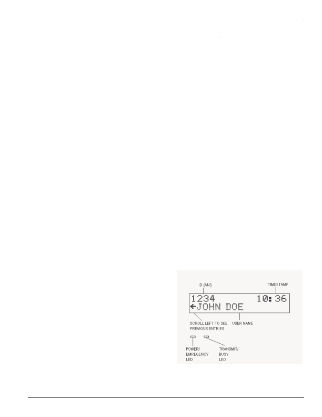
4.1.1 Reading the Display
ID (ANI) – This is the numeri c ID (or ANI) of the user
who last transmitted on the channel. When an
emergency ANI is received, this area will alternate
DDU-300 Manual Rev. 2006.02.22
Page 6
PAGE 6 MIDIAN ELECTRONICS INCORPORATED
between displaying the ANI and the message
'EMERGENCY' every 2 seconds.
TIMEST AMP – This is the t ime of day that the last ANI
was received. The timestam p is in 24-hour form at. In
24-hour format, 4 A.M. is displayed as 04:00 and 4
P.M. is displayed as 16:00. Note that the timestamp
changes only when a new ANI comes in, it is not
time-of-day clock.
USER NAME – This is the name of the user
associated with the numeric ID that was received. User
names are stored in a database. The database must
be confi gur ed before nam es can be displayed.
SCROLL LE FT I NDICAT OR – I ndi cates that ther e are
other ANI’s previously logged. Press the left
<SCROLL> button to view the previously logged
items.
POWER / EMERGENCY LED – Glows green when
power is tur ned on. Blinks between orange and green
to indicate that an emergency ANI was received
recently. This indicator remains blinking until the
operator presses any key.
TRANSMIT / BUSY LED – This LED i s off when there
is no activity. It glows red during transmit. It blinks
green any ti m e t he radi o channel is busy (provided t he
COR input is connected).
a
4.1.2 Keypad Operation in Display Mode
<SCROLL> LEFT - When in Display Mode, the
keypad <SCROLL> keys are used to scrol l thr ough the
previously logged ANI’s. The scroll left indicator
remains present on the screen so long as there are
more previous entries to be viewed. The scroll left
indicat or disappears when the oldest entry is reached.
<SCROLL > RIGHT - A scroll right indicator will appear
on the right side of the screen when there are newer
entries available for viewing. Press the right
<SCROLL> button to view the newer entries. When
the last entry is reached, the right scroll indicator
disappears.
<#> POUND KE Y – Repeatedly pressing the <#> key
will always return the DDU to display mode with the
last ANI rec eived being shown.
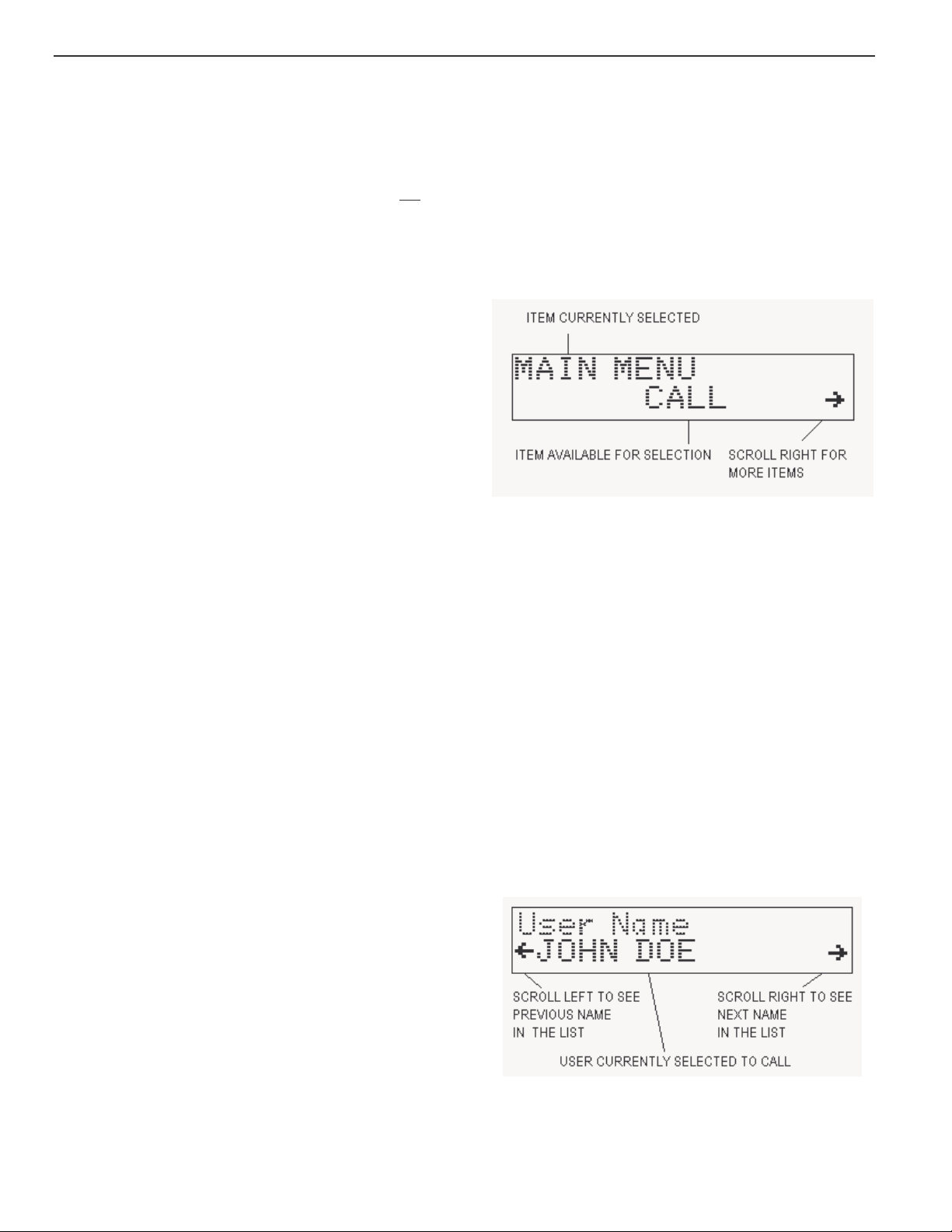
4.2 MENU MODE
The Menu Mode provides the method for configuring
the DDU.
4.2.1 Navigating the Menus
Press the star key <*> whil e in Display Mode to place
the unit into Menu Mode. Upon entry to Menu Mode,
you will be in the Main Menu. The top line of the
display i ndic ates thi s. The bot tom l i ne di splays an i tem
available for selection, in this case the CALL
command.
The scroll right symbol on the right side of the displ ay
indicat es that addit ional it ems are av ai lable. Press the
right <SCROLL> button to view the next available
item. The scroll left symbol will then appear, indi cat ing
that the left <SCROLL> button may be used to go
back to the previous i tem.
To select the displayed item, press the <SEND>
button (the <SEND> button acts like an ENTER key
when in m enu m ode). Upon select ion, the nam e of the
item will appear on the top line of the display. The
bottom line will present additional i tems for select ion.
Press the <#> key to return to the pr evious selec tion.
4.2.2 Calling a Unit in the Database
To plac e a call t o a unit in the database, f irst select
CALL from the Main M enu. Press the right < S CROLL>
button to di splay the f irst user in the database. Either
the User ID will be displayed, or the User Name (alias)
will be displayed. This is determined by the Call Entry
Mode setting.
<MONITOR> - This button always control s the moni t or
functi on of the radi o. Press <MONI TOR> to toggl e the
state of t he monitor output to the radio.
<SEND> - A ctiv ates the radio P TT switch, pl acing the
radio in transmit mode. This function applies only to
units equipped wit h a microphone.
NUMBER KEYS – The number keys perform no
function in display mode. They are used in menu
mode f or data entry.
<*> STAR KEY – Pressing the <*> will place the DDU
in Menu Mode at the main menu.
The left and right scroll indicators will appear on the
bottom line. This is the Select Mode. Use the
<SCROLL> k eys to locate the desired user withi n the
database. When the name is located, press the
<SEND> key to place the call. The <#> key m ay be
DDU-300 Manual Rev. 2006.02.22
Page 7

MIDIAN ELECTRONICS INCORPORATED PAGE 7
used at any tim e prior to pressing <SEND> to cancel
the call .
To loc ate a user in the database more quickly, you can
enter one or more of the f irst few digits/letters of the
User ID/Name prior to pressing the right <SCROLL>
button. The DDU will search the database for users
matching the first few digits/letters.
4.2.3 Calling a Unit Not in the Database
To plac e a cal l to a unit which is not in the dat abase,
start by selecting CALL from the Main Menu or by
pressing a num ber key whil e in display mode. Instead
of pressing the r ight <S CROLL> button, simpl y key the
numeric ID of the user to be cal led using the keypad.
Press <SEND> to initiate the call. The left <SCROLL>
key may be used as a backspace key to correct any
errors made duri ng entr y. T he < #> key may be used at
any time prior to pr essing <SEND> to cancel the call.
4.2.4 Numeric vs. Alphanumeric Entry
There are two dif ferent data entry m odes avail able on
the DDU. As shipped f rom the factory, Numeric entry
is the default mode when calling a unit. As numbers
are entered, they appear on the bottom-left of the
display. Pressing the <*> key while in numeric entry
mode changes the mode to Alphanumeric.
In alphanumeric mode, you may type in letters and
numbers as described in t he next section. This allows
you to ty pe the nam e of a user in the dat abase without
havi ng to scr oll t hrough the nam es. Alphanum eri c data
appears on the bottom line of the display as it is
entered. You may make alphanumeric call entry the
default m ode by c hanging t he Call Entry Mode setting
in the CONSOLE SETUP menu.
4.3.3 E ntering Alphanumeric Data
Entering alphabetic charact ers into the user database
using the numer ic keypad is easy. All of the lett ers of
the alphabet appear above the numbers on the
keypad. F or ex ampl e, the let ters ‘A’ ‘B’ and ‘C’ appear
on the <2> key .
Alphabeti c charact ers are entered by pressing 2 digit s.
The first digit is the key with the desired letter
appearing on it . The 2
on that key. F or exam ple, the code f or the l etter ‘C’ is
23 since it i s the 3
is the 1
To enter num eric characters i n an alphanumeric fi eld,
press the <0> key followed by the desired digit.
Punctuation characters such as comma <,> and <->
do not appear on the keypad. Special codes have
been assigned to allow entry of those characters.
Please refer to the f ollowing chart
The code 10 is used to insert a space between
characters.
st
letter on the <8> key, so its code is 81.
A=21 I=43 Q=72 Y=93 7=07 - =15
B=22 J=51 R=73 Z=94 8=08 = =16
C=23 K=52 S=74 1=01 9=09 * =17
D=31 L=53 T=81 2=02 0=00 / =18
E=32 M=61 U=82 3=03 , =11 # =19
F=33 N=62 V=83 4=04 . =12 Spc=10
G=41 O=63 W=91 5=05 _=13
H=42 P=71 X=92 6=06 +=14
4.3 USER DATABASE
The user database makes day-t o-day operation of the
DDU much easier. You can use easy-to-remember
names instead of just number s.
4.3.1 User Database Features
The primary purpose of the user database is to
associate names with numbers. This way, when an
ANI comes in, the name of the person can be
displayed al ong with the ANI.
The DDU can store up t o 137 names and ID number s
in its database. The DDU retains the database
memor y even when switched off.
4.3.2 Setting Up the User Database
Begin by compiling a list of names and ID numbers.
Give some thought on how you are going to abbreviate
the names since only 14 characters per name are
available. To begin entering data, select Add User
from the USERS menu.
4.3.4 Numeric vs. Alphanumeric Entry
There are two dif ferent data entry m odes avail able on
the DDU. Numeric ent ry is f or entr y of User I D codes.
Alphanumeric entry is used when entering User
Names to the dat abase. W hen select ing a user in t he
database to be edited or del eted, ei ther mode may be
used.
As shipped from the factory, numeric is the default
mode f or sel ect ing a uni t t o edi t or del et e. As num bers
are entered, they appear on the bottom-left of the
display. Pressing the <*> key while in numeric entry
mode changes the m ode to Alphanumeric. You may
make this the default by changing the Data Entry
Mode in the CONSOLE SETUP menu.
4.4 MISCELLANEOUS FEATURES
4.4.1 Locking and Unlocking Menus
The menu system incorporates a lock feature to
prevent unauthorized personnel from changing the
DDU configuration. The lock feature also serves to
DDU-300 Manual Rev. 2006.02.22
nd
digit is the position of the letter
rd
letter on the <2> k ey . The letter ‘T’
Page 8

PAGE 8 MIDIAN ELECTRONICS INCORPORATED
simplify day-to-day operation of the unit. When the
LOCK command is selected, all of the menus are
disabled. The only item available will be UNLOCK.
Selecting UNLOCK makes all of the menu items
available again.
entering a partial name or ID, press the right
<SCROLL> but ton and find the user you wish to call.
Remember, you can use the <*> to toggle between
numeric and alphabetic entry modes.
5.2 ACTIONS MENU
When locked, the unit is password protected so only
authorized personnel may unlock the menus. As
shipped from the factory, the security feature is
disabled and the LOCK/UNLOCK options do not
appear. To enable t he feature and select a password,
see the SECURIT Y S E TUP menu item.
Remember your passw ord! Once securit y is enabled
and the m enus are locked, the only way to unloc k will
be to use the password. If you do f orget the password,
contact Midian f or the reset procedure.
4.4.2 Emergency/Status Display
Upon receipt of an emergency ANI, the emergency
LED will blink and an alarm siren will sound (if
enabled). Also, the ANI and the 'EMERGENCY'
message are placed on the 1
alternating every 2 seconds so that the user can be
identified.
Up to 11 status m essages can be program med in total.
All but status 9 and 10, are blank. Status 9 is reserved
for EMERGENCY, and status 10 is reserved for
DISABLED. Status message 0 i s usually referred to as
NO STA TUS, and should be l ef t blank . T he actual t ex t
of the 10 stat us messages 0-10 may be programm ed
to any 10-character message you wish. Examples of
which are EN-ROUT E , OFF DUTY , etc.
st
line of the display,
5.2.1 Prog Key 1 command
Reprograms securit y key code #1 over the air (OTAR
feature) . See S et Key # i n the ADMIN menu to change
the key. Simply enter the 4-digit code of the unit, or
select from the database as if using the CALL
command.
5.2.2 Prog Keys 1-2 command
Reprograms security key codes #1 and #2 ov er the air.
5.2.3 Prog Keys 1-3 command
Reprograms security key codes #1, #2, and #3 over
the air.
5.2.4 Prog Keys 1-4 command
Reprograms al l f our securi ty key codes #1 through #4
over the air.
5.2.5 Spy command
Commands a unit to self -key for a short tim e allowing
you to listen in. The amount of time can be 0-90
seconds depending on how the scrambler is
programm ed. Si mpl y enter t he 4-digi t code of the unit,
or select from the database as if using the CALL
command.
4.4.3 Repeater Access Control
The DDU can be interfaced to a repeater to limit
access only to those users who are authorized. T his is
accompl i shed by requi ri ng an ANI of the pr oper f or m at
before granting access. Access can be further
restricted by requiring that the ANI match a User ID
stored in the database. See REPEATER SETUP for
more inform ation.
5.2.6 Query command
Commands a uni t to report it s ANI and status. This is
sometim es ref erred to as a ‘radio chec k’. Si mpl y enter
the 4-di git code of the unit, or select from the database
as if using the CALL command.
5.2.7 Clea r ANI Log command
Allows you to cl ear the ANI log without having t o turn
the unit off and bac k on.
5 MENU SYSTEM
The following sections describe the various functions
of the menu system. Factory default settings are
underlined
.
5.1 CALL COMMAND
Allows you to place a call to a unit or units. You will be
giv en the option to ent er the 4-digit num eric ID of the
unit y ou wish to c all. If the user dat abase i s set up, y ou
may use the r ight <SCRO LL> buttons to go into Select
Mode and fi nd t he nam e of t he user to be cal l ed using
the left and right <SCROLL> keys.
Alternat iv ely, you can ent er the User ID or User name
in part or in whole. When enter ing the com pl ete name
or ID, simply press <SEND> to place the call. When
5.3 LOCK OR UNLOCK COMMAND
Note The LOCK and UNLOCK menu options do not
appear unless enabled in SECUIRT Y SETUP.
Selecting LOCK will disable access to the rest of the
menu system described in the following sections.
Select UNLOCK to enable the entire menu system.
You must enter a 4- digit password to unlock the m enu
system. See SECURITY SETUP for more information.
5.4 USERS MENU
5.4.1 Add User menu
Allows you to add a new user to the database. When
DDU-300 Manual Rev. 2006.02.22
Page 9

MIDIAN ELECTRONICS INCORPORATED PAGE 9
ADD USER is selected, you will be prompted to fill in
the User ID and User Name for that user.
5.4.1.1 User ID field
This numeric field contains the primary ANI number
assigned to the user’s radio. T he digits can be 0-9.
Range: 4 digits
Default: blank
5.4.1.2 User Name field
This alphanum eric f ield cont ains the name of the user
associated with the user ID. A maximum of 14
characters may be used. See the Entering
Alphanumeric Data section for more information.
Range: 0-14 characters
Default: blank
5.4.2 Edit User menu
Allows you to change inf ormati on about a user. W hen
you choose EDIT USER ( or Delete User) the lef t and
right scroll indicators will appear on the bottom line.
This is the Select Mode. Use the < SCROLL> keys to
locate the desi red user within the dat abase. When the
name is located, press the <SEND> key to edit that
user record.
To loc ate a user in the database more quickly, you can
enter one or more of the f irst few digits/letters of the
User ID/Name prior to pressing the right <SCROLL>
button. The DDU will search the database for users
matching the first few digits/letters.
All 8 digits must be entered.
Range: 8 digits
Default: 22223456
5.5.3 Set Key #3 setting
Allows you to m odify security key code #3. The key is
sent when either the Pro g Keys 1-3 o r Pro g Keys 1-4
comm and is issued. All 8 digits m ust be entered.
Range: 8 digits
Default: 33334567
5.5.4 Set Key #4 setting
Allows you to m odify security key code #4. The key is
sent when the Prog Keys 1-4 comm and is issued. Al l
8 digits must be entered.
Range: 8 digits
Default: 44445678
5.5.5 Disable Unit command
Allows you to rem otely disable a uni t. This is useful if
the unit is lost, stolen, or the user didn’t pay their bill.
Simpl y enter t he 4-di gi t code of the unit , or select f rom
the database as if using the CALL command.
5.5.6 Enable Unit command
Allows you to remotely enable a unit that was
previously disabled. Simply enter the 4-digit code of
the unit, or select from the database as if using the
CALL command.
5.4.3 Delete User menu
Allows you to delete a user recor d from the database.
When DE LETE USER is selected, you will be able to
select the user you wish to del ete in t he same m anner
as if select ing a user to edit. Use the scroll buttons to
find the user you wish to delete. Press <SEND> to
delete the selected user. You will have to press
<SEND> a second time to confirm. Press <#> to
cancel if you change your mind.
5.5 ADMIN MENU
5.5.1 Set Key #1 setting
Allows you to m odify security key code #1. The key is
sent when one of the Prog Key(s) c ommand is issued.
All 8 digits must be entered.
Range: 8 digits
Default: 19981998
5.5.2 Set Key #2 setting
Allows you to m odify security key code #2. The key is
sent when one of the Prog Keys comm and is issued.
5.6 SETUP MENU
5.6.1 SOUNDS SETUP menu
5.6.1.1 Keypad Beep option
Turning this option on causes a beep to be heard for
each key press.
OFF Keypad beeps off.
Keypad beeps on.
ON
5.6.1.2 Beep On ANI option
Turning this option on will cause an alert beep to be
heard ever y tim e a new ANI is received.
OFF Do not beep when ANI comes i n.
Beep when ANI comes in.
ON
5.6.1.3 Emerg Siren option
This causes a siren sound to be heard when an
emergency AN I is received.
Do not sound siren on emer genc y A NI.
OFF
DDU-300 Manual Rev. 2006.02.22
Page 10

PAGE 10 MIDIAN ELECTRONICS INCORPORATED
ON Sound siren on emergency A NI.
5.6.1.4 Internal Speaker setting
Normally, the internal speaker is on and audio from
the radio can be heard. If this is not desired, change
this setti ng to OFF. The enabled beep features can still
be heard however. If it is desired that absolutely no
sound be heard from the console speaker, simply
disconnect i t.
OFF Internal speaker disabled.
Internal speaker enabled.
ON
5.6.1.5 Auto Mute Speaker feature
This feature is designed to mute the internal speaker
while an ANI is being recei v ed. It works in conjunc tion
with the Auto Mute Time. When this feature is
enabled, the internal speaker rem ains muted so long
as there is no COR indi cation comi ng from the radio.
When the COR indication goes active, the internal
speaker will automatically unm ute after the Auto Mute
Tim e expires. Note: System sounds can still be heard
during the mute period.
Do not mut e the internal speaker.
OFF
ON Mute/unmute speaker automatically .
5.6.1.6 Auto Mute Time setting
This is used in conjunction with the Auto Mute
Speaker feature. This specifies how long the DDU
internal speaker will remain muted af ter the COR input
goes activ e. This v alue should be set to allow for any
key-up delay of the transmitting unit as well as the
time it takes for the ANI to complete.
Range: 0000 to 4000 milliseconds
Default: 0600
milliseconds
5.6.3 CONSOLE SETUP menu
5.6.3.1 Data Entry Mode setting
Determines if numeric entry or alphanumeric data
entry i s t he def aul t m ode when select ing a r ecord. The
mode of entry can be toggl ed by pressing the <*> key
during data entry (except when entering ANI's).
NUMERIC
ALPHA Start entr y in alphanum er ic mode.
Start i n numeric only mode.
5.6.3.2 Ignore Nonuser option
Turning on this option helps prevent the display of
false decodes by i gnoring ID’s which do not appear in
the user database. This can also be used to restrict
access to a repeat er to only those ID’s i n the database.
See REPEATER SETUP for more information.
Display ID’s not in database.
OFF
ON Ignore ID’s not in database.
5.6.3.3 Fast Scrolling setting
Fast Scrol ling al lows for f aster navi gation through the
menu system. The DDU c an also ani m ate t he scrolling
of t he screen f rom side-to- side. This prov ides positi ve
feedback in response to scrolli ng through menus and
the ANI l og. I f t his eff ect is desired, F ast Scrol ling c an
be disabled.
OFF Animate scrolling from side to side.
Scroll at fast speed.
ON
5.6.3.4 Contrast setting
Allows the display contrast to be adjusted for best
viewing.
Low contrast setting.
LOW
5.6.2 TIME SETUP menu
In order for t he correct tim e to be displayed, t he time
clock must be set. The unit must remain switched-on
at all times in order to keep track of the time. The
clock must be set each time the unit is powered up.
5.6.2.1 Hour setting
Set the hour of the day in 24-hour f ormat. Enter two
digits.
Range: 00-23
Default: 00
5.6.2.2 Minute setting
Set the m inutes past the hour. Enter two digits.
Range: 00-59
Default: 00
HIGH High contrast setting.
5.6.3.5 Mic. Option setting
Selects which type of optional microphone accessory
is attached to t he DDU. This is necessary so that the
DDU knows how to treat the ext er nal signals.
No micr ophone.
NONE
GOOSENECK Gooseneck sty le mi c r ophone.
PADDLE Paddle styl e deskt op microphone.
HANDSET External handset.
5.6.3.6 Printer Option
The DDU, i f ordered wit h the printer cable option, can
log the ANI t raff ic to a serial pri nter. The pri nter must
have a print buffer and a standar d RS - 232 por t. It must
be conf igured for 9600 baud, 8 data bits, 1 stop bit and
no parity. In order to send data to the printer, this
DDU-300 Manual Rev. 2006.02.22
Page 11

MIDIAN ELECTRONICS INCORPORATED PAGE 11
option m ust be on.
OFF
Do not send data to pri nter.
ON Send data to printer.
5.6.4 SECURITY SETUP menu
5.6.4.1 Security setting
Allows the security option to be turned on and off. If
turned off, the LOCK/UNLOCK menus will not appear.
ON Enable security feature.
Disable securi ty featur e.
OFF
5.6.4.2 Password setting
Sets the password required to UNLOCK the menu
system when the Security is turned on. Must be 4
numeric digits.
Range: 4 digits
Default: 0000
5.6.5 ENCODER SETUP menu
5.6.5.1 Keyup Delay setting
This sets the Key-Up Delay, also known as Front
Porch Time. This is the am ount of time the DDU will
wait aft er asserting PTT before sending data over the
air. This tim e allows for del ay s i ntroduced by repeaters
and decoding of squelch control si gnals such as
CTCSS.
Range: 0 to 9 x100 milliseconds
Default: 4
x 100 milliseconds
5.6.5.2 Preamble setting
Normally, the DDU will send just carrier or ‘dead air’
during the Keyup Delay per iod. Optionally, it can send
a continuous preamble tone duri ng this time. This i s
provided primarily for voters.
no preambl e during keyup delay
OFF
ON preamble sent during keyup delay
Channel is busy when COR is 0V.
LOW
HIGH Channel is busy when COR is 5V.
5.6.5. 4 Busy Lockout option
This opti on prevents the DDU from transmi tting on a
busy channel. If this option is ON, the unit will not
transmit when the COR input is i n the active state. The
DDU will wait until the channel is clear and then
transmit. When this option is OFF, the unit will
transmit regardless of t he state of the CO R input.
Transmit regardless of COR input.
OFF
ON Do not transmi t when channel busy.
5.6.5.5 System ID se tting
The scramblers will not accept commands from the
DDU unless the System I D matches that programm ed
into t he scramblers. The S ystem ID in the scr amblers
is set at the f actory. Normal ly, the system ID i s 1230
unless a custom System ID was specified when the
scramblers were ordered. Only change this setting if
you know you have a c ustom System ID.
Range: 4 digits
Default: 1230
5.6.6 REPEATER SETUP menu
5.6.6.1 Repeat Control option
Allows the DDU to control access to a repeater.
Causes the DDU t o assert a PTT out put to a repeater
upon receipt of either: (1) any ANI in the format
decoded by the DDU or ( 2) a v ali d User ID in t he user
database. To restrict r epeater access to valid User ID’s
only, the Ignore Nonuser option in the CONSOLE
SETUP m ust be turned ON. O therwise, any incom ing
ANI of the proper for mat will be considered v alid.
Other possible uses of the Repeat Control option
include operat ion of a horn relay or the enabling of a
PA speaker. Repeater c ontrol output can either be the
PTT output , or the MONI TOR output (see below).
Repeater control disabled.
OFF
ON Repeater control is enabled.
5.6.5.3 COR Polarity setting
Determines which state of the COR (carrier detect)
input is considered the active state. When COR is
activ e, the radio channel is busy. If the radio is using
PL/CTCSS, it is recom mended that the COR Input be
connected to a point which goes active when PL is
detected.
The COR input is used in conjunction with the Busy
Lockout feature. If not connecting t he COR input, do
not enable Busy Lockout .
5.6.6.2 Validate Time setting
This sets how long aft er COR becom es active, that the
repeater will be keyed prior to receiving a valid
decode. This allows time for the incoming ANI to be
broadcast by the repeat er bef ore it has been validat ed.
If no ANI (or vali d User ID) has been decoded during
this tim e, the repeater will be un-keyed. The repeater
will rem ain un-keyed until COR goes inactiv e.
If set t o 0, the repeat er will not be keyed until after the
ANI (or vali d User I D) has been decoded.
DDU-300 Manual Rev. 2006.02.22
Page 12

PAGE 12 MIDIAN ELECTRONICS INCORPORATED
Range: 00 to 99 10ths of a second (0. 0 - 9.9 s)
Default: 10
10ths of a second (1.0 second)
5.6.6. 3 PTT Hang Time setting
Once validation has occurred, this sets how long the
repeater will remain keyed after COR goes inactive.
Once the hang t imer ex pires, a new vali dation will be
required to ac c ess the repeat er .
Range: 00 to 99 10ths of a second (0. 0 - 9.9 s)
Default: 20
10ths of a second (2.0 seconds)
5.6.6.4 Hang Reset setting
This setti ng speci f i es what is requi red t o reset t he PTT
hang tim er before it expires. This can either be COR
or COR+ANI . When set to CO R, t he hang tim er will be
reset if COR goes active prior to ex piration, allowing
the conv ersation to conti nue without a new v alidat ion.
When set to COR+ANI, a new valid ANI will also be
required to k eep the repeater open.
Reset hang timer if COR goes activ e
COR
before the hang time expires.
COR+ANI Require both COR and an ANI (or
val id User ID) to reset the hang timer
before expiration.
5.6.6.5 Repeater Out setting
This setti ng specifies which output is used to put the
repeater into transmit mode when Repeat Control is
enabled.
PTT output used to key repeater in
PTT
Repeat Control mode.
MONITOR MONI TOR output used to key repeater
in Repeat Control mode.
5.6.7 STATUS SETUP menu
5.6.7.2 Status 1 Msg setting
See Status 0 Msg setting above.
Range: 0-10 characters
Default: blank
5.6.7.3 Status 2 Msg setting
See Status 0 Msg setting above.
Range: 0-10 characters
Default: blank
5.6.7.4 Status 3 Msg setting
See Status 0 Msg setting above.
Range: 0-10 characters
Default: blank
5.6.7.5 Status 4 Msg setting
See Status 0 Msg setting above.
Range: 0-10 characters
Default: blank
5.6.7.6 Status 5 Msg setting
See Status 0 Msg setting above.
Range: 0-10 characters
Default: blank
5.6.7.7 Status 6 Msg setting
See Status 0 Msg setting above.
Range: 0-10 characters
Default: blank
5.6.7.8 Status 7 Msg setting
See Status 0 Msg setting above.
5.6.7.1 Status 0 Msg setting
There is a status message for each of the digits 0
through 9. These correspond to the first digit of a
status/location packet sent by the TVS-2. Emergency
packets always begin with the digit 9 and thus status
message 9 should always be associated with
emergency status (though the tex t may be changed). A
special status code is sent by the scrambler when it
has been remotel y disabled. Status 10 i s reserved f or
this code. Each status message may be up to 10
alphanumeric characters. If not using status
messages, or if certain digits are not used, simply
leave those blank.
Range: 0-10 characters
Default: blank
Range: 0-10 characters
Default: blank
5.6.7.9 Status 8 Msg setting
See Status 0 Msg setting above.
Range: 0-10 characters
Default: blank
5.6.7.10 Status 9 Msg setting
See Status 0 Msg setting above.
Range: 0-10 characters
Default: EMERGENCY
5.6.7.11 Status 10 Msg setting
See Status 0 Msg setting above.
DDU-300 Manual Rev. 2006.02.22
Page 13

MIDIAN ELECTRONICS INCORPORATED PAGE 13
Range: 0-10 characters
Default: DISABLED
5.6.8 UTILITIES menu
5.6.8.1 Reset Defaults
This will reset all the parameters listed above to the
factory default settings. The contents of the user
database will not be affected.
5.6.8.2 Clear Database
This will clear the user database of all ID's and User
Names. The contents of the other parameters listed
above will not be affected.
5.6.8.3 Factory Debug
This is used by the f actory f or product testi ng. Do not
select this function unless directed to do so by
Midian Technical Support. Damage to the unit may
result.
DDU-300 Manual Rev. 2006.02.22
Page 14

PAGE 14 MIDIAN ELECTRONICS INCORPORATED
6 SYSTEM ERROR MESSAGES
CHANNEL BUSY
Reason: An attempt was made to tr ansmit on a busy
channel with busy l oc k out enabled.
Solution: Wait until the channel is clear before
transmitting.
DATABASE EMPTY
Reason: An attem pt was made t o edit or del ete a user
when the database was empty.
Solution: These functions do not apply when the
database is empty .
DATABASE FULL
Reason: An attempt was made to add a user to the
database and there is no more room. The maximum
number of user aliases of 137 cannot be exceeded.
Solution: Remove any old user names that are no
longer in serv i ce. If thi s is not possible, contact Midi an
to learn about our Computer Aided Dispatch (CAD)
fleet management systems which can handle many
more users.
DATABASE ERROR
Reason: One or m or e ent ri es in t he user database has
been corrupted. Thi s c an happen if power is lost at t he
exact time the database is being updated. Any
corrupted records will be blanked-out and must be reentered.
Solution: Cy cl e power to the uni t . T his should c lear the
error. If the error message continues to come up,
contact Midian technical support.
DUPLICATE ID
Reason: An attem pt was made t o add a user ID to the
database which is al ready in the database. Each user
ID in the dat abase must be unique.
error. If the error message continues to come up,
contact Midian technical support.
EE WRITE FAIL
Reason: The EEPROM chi p or connections to it have
failed.
Solution: Cont act Mi dian f or i nstructi ons on getting t he
unit repai red.
MODEM TIMEOUT
Reason: The LTR input is being used and a channel
could not be acquired on the trunking system. The
DDU will wait about 4.5 seconds for the LTR i nput to
go high befor e issuing this message and aborting the
comm and in progress.
Solution: Try issuing the com mand again.
Reason: The m odem (encode/decoder) secti on of the
DDU is not responding to commands. This could be
the result of a hardware fai lure.
Solution: Cycle power to the unit, Reset default
parameters via the UTILITIES menu. Cycl e power to
the unit once agai n. If the error m essage continues to
come up, contact Midian technical support.
NOT F OUND
Reason: There is no entry in the user database that
matches the dat a entered.
Solution: W hen selecti ng a user to edit or delete, the
name or the ID can be entered in whole or in part.
When entering a partial name or ID, press the right
<SCROLL> button t o search the database f or the f irst
partial match. Press <SEND> only i f the whole ID or
name has been entered. T here may be no entry i n the
database that matches in whole or in part. In that case,
the user is not in the database.
Solution: Choose a unique user ID for eac h user. If i t is
necessary to edit t he user rec or d, use the edit menu.
EE CHKSUM ERR
Reason: The confi guration settings stored in EEPROM
have been cor rupted. Thi s can happen if power is lost
at the exact time a parameter is being updated. All
configuration settings will be set back to defaults. The
user database should not be affected.
Solution: Cy cl e power to the uni t . T his should c lear the
DDU-300 Manual Rev. 2006.02.22
Page 15

MIDIAN ELECTRONICS INCORPORATED PAGE 15
7 MENU SYSTEM MAP
DDU-300 Manual Rev. 2006.02.22
Page 16

- This page intentionally left blank -
Page 17

Page 18

Page 19

Page 20

Page 21

Page 22

 Loading...