

Page 1

DDU-100
Local Remote Controller with DTMF Encode & ANI Decode
DDU-200
Local Remote Controller with 5-Tone Encode & ANI Decode
INSTRUCTION MANUAL
Model Features
10 entry ANI recall memory
137 entry alias database
Auto-mute leading ANI
Alternate function as a repeater access controller
MANUAL REVISION: 2013-07-22
COVERS PRODUCT SOFTWARE VERSION(S):
1.1 _____ _____ _____ _____
WITH EN
1.7 _____ _____ _____ _____
CODER/DECODER VERSION(S):
Programmable encode/decode format
Supports DTMF and several 5-tone formats
Easy to read backlit LCD display
Serial printer logging (w/optional cable)
COPYRIGHT 2001-2004 MIDIAN ELECTRONICS INC. ALL RIGHTS RESERVED.
MIDIAN ELECTRONICS, INC.
To Order: 1-800-MIDIANS
DDU-100/200
2030 N. Forbes Blvd. #101
Telephone: (520) 884-7981
Tucson, Arizona 85745
Email: sales@midians.com
Page 2

1 SPECIFICATIONS
Voltage/Current
Operating Voltage (nominal) ................................. 12 VDC
Operating Voltage (min-max) ........................... 12-15 VDC
Operating Current (standby @12 VDC) ................. 100 mA
Operating Current (peak @15 VDC) ...................... 500 mA
Inputs
Input Level (RX) ..................................... 100-3000 mV p-p
Input Impedance (RX) ............................................. > 10k
Outputs
Output Level (TX, unloaded) .................. 150-2500 mV p-p
Output Impedance (TX) ........................ 27k with JU4 cut
Speaker Audio Output ..................................... 1 W into 8
Mechanical
Dimensions: ..................................... .2⅞"H x 6½W x 8¾"L
Operating Temp ................................................ 0° to 50° C
Encode/Decode Formats
DTMF, CCIR, EEA, EIA, ZVEI, DZVEI, DDZVEI, NATEL,
and MODAT.
Other
Max ANI Length ..................................................... .8 digits
ANI Recall Stack Size .................................................. .10
Alias Database Size ................................................... .137
DDU-100/200 Manual
Page 3

MIDIAN ELECTRONICS INCORPORATED PAGE 3
TABLE OF CONTENTS
1 SPECIFICATIONS ........................................................................................................................... 2
2 OVERVIEW ................................................................................................................................ 4
3 INSTALLATION INSTRUCTIONS .............................................................................................. 4
3.1 RADIO INTERFACE................................................................................................................................. 4
3.2 JUMPER SETTINGS ................................................................................................................................ 5
3.3 ADJUSTMENTS ...................................................................................................................................... 5
3.4 CONFIGURATION SETTINGS ................................................................................................................... 5
4 BASIC
4.1 DISPLAY MODE ..................................................................................................................................... 5
4.2 MENU MODE ......................................................................................................................................... 6
4.3 USER DATABASE .................................................................................................................................. 7
4.4 STATUS DISPLAY FEATURE ................................................................................................................... 8
OPERATION .................................................................................................................. 5
5 MENU SYSTEM .......................................................................................................................... 8
5.1 CALL COMMAND ................................................................................................................................... 8
5.2 LOCK OR UNLOCK COMMAND ............................................................................................................. 8
5.3 ACTIONS MENU................................................................................................................................... 8
5.4 USERS MENU ...................................................................................................................................... 8
5.5 SETUP MENU....................................................................................................................................... 9
6 SYSTEM ERROR MESSAGES ................................................................................................ 14
7 MENU SYSTEM MAP ............................................................................................................... 15
DDU-100/200 Manual
Page 4

PAGE 4 MIDIAN ELECTRONICS INCORPORATED
impedance of the DDU can be adjusted if necessary by
2 OVERVIEW
The DDU provides the optimal ANI display decoder
solution for small and medium sized radio systems
such as those used by taxi fleets, police departments,
construction crews, etc. It offers many features
normally found only in large and expensive Computer
Aided Dispatch (CAD) systems in one compact
desktop unit.
It can encode and decode most popular tone signaling
formats. The last 10 ANI's received can be reviewed at
any time. It can store up to 137 aliases in its user
database. The user friendly menu system makes it as
easy to use as a cell phone. Additional features include
status display and the ability to automatically mute
incoming leading ANI's
replacing leaded resistor R81 with an appropriate
value.
PTT OUTPUT (P1-3) [Yellow]
This open collector output provides a ground to key-up
the radio when transmitting. If connecting to a relay in
the radio, make sure the coil is bypassed with a diode
to eliminate counter-EMF.
This output may also be assigned to be the repeater
access control output. See REPEATER SETUP for
more information.
COR INPUT (P1-1) [Gray]
3 INSTALLATION INSTRUCTIONS
Installation Note: Midian products utilize CMOS integrated
circuits, which are susceptible to damage from high static
charges. Be sure to follow standard antistatic procedures
when handling, including using grounded workstations and
soldering irons and wearing grounding bracelets.
3.1 RADIO INTERFACE
Radio Interface connector P1 is an 8-pin
RJ-45 style connector in the center of the
back panel.
+V IN (P1-5) [Red]
The DDU can be powered either by an optional wall
transformer or by the radio power supply. Connect this
wire to the radio power source provided it is between
12 and 15 VDC.
If using a wall transformer, make sure the voltage is
between 12 and 15 VDC and the current rating is at
least 800mA. Also, be certain that positive is
connected to the inside ring.
GROUND (P1-6) [Black]
Connect to radio ground.
AUDIO INPUT/RX IN (P1-8) [Blue]
Connect to a point in the radio where receive audio is
present at a constant level. If using PL or CTCSS, be
sure to connect to a point after the CTCSS high pass
filter. If using the Squelch Output of the DDU, be sure
the RX audio point is not muted when the radio is
squelched.
AUDIO OUTPUT/TX OUT (P1-4) [Green]
Connect to the mic-hi input of the radio. The output
Connect to a point in the radio squelch or CTCSS
circuit that changes logic level when carrier (or
CTCSS) is detected. A radio whose circuitry provides a
logic-low or logic-high can readily turn Q1 on and off. If
only a high level is provided, it may be necessary to
move R40 from its pull-up to its pull-down position.
Note that it is required that the COR Input be in the
active state in order to decode all formats except
DTMF. If COR is not to be connected, make sure it is
programmed to be active HIGH. A COR connection is
required in order to use busy lockout, auto ANI mute,
and repeater access control features.
MONITOR OUTPUT (P1-7) [Orange]
This output can be used to control the monitor function
of the radio using the <MONITOR> button on the DDU.
This is an open collector output which changes state
each time the <MONITOR> button is pressed.
This output may also be assigned to be the repeater
access control output. See REPEATER SETUP for
more information.
SQ OUT/LTR IN (P1-2) [Brown]
This wire may be either a Squelch Output or a
Trunking Delay (LTR) input, but not both. To use as a
squelch output, install jumper R85 and make sure
jumper JU5 is not installed. To use as a trunking delay
input, remove R85 and install JU5.
When used as a Squelch Output, connect to a point in
the radio which will mute the speaker when brought to
ground (or left floating). Program the appropriate
polarity in the RADIO SETUP menu.
When used as an LTR Trunking Delay Input, connect
to a point in the radio which changes state between 0
and 5 VDC when a channel has been acquired on the
LTR trunking system. The active (channel acquired)
state of this input is programmable in the RADIO
SETUP menu.
DDU-100/200 Manual
Page 5
MIDIAN ELECTRONICS INCORPORATED PAGE 5
3.2 JUMPER SETTINGS
There are two user configurable jumpers, JU1 and
JU4. Both are installed at the factory. JU1 allows
signaling audio to be heard in the local speaker. If this
is not desired, cut JU1.
JU4 controls the output impedance of transmit audio.
See OUTPUT LEVEL below to determine if JU4 will
need to be cut.
3.3 ADJUSTMENTS
Once the unit has been connected to the radio, several
adjustments must be made to achieve proper
operation. It will be necessary to open the unit. Use the
pictorial to identify the location of the following trim
pots: R2 and R32 near connector P3, R51 near IC U6,
and R105 near the volume control.
INPUT LEVEL (when using decode feature)
Use a service monitor to generate a 1000 Hz test tone
at 2/3 of maximum system modulation (typically 3.3
kHz). Measure the voltage appearing at TP1 and
adjust R2 such that TP1 is at 250mV RMS.
It is also important to program COR Polarity to match
that of the radio. If this is not set properly, the DDU will
not decode some of the formats.
Be sure to set the time of day via TIME SETUP once
the DDU is operating as desired. Once the time is set,
be sure to leave the unit on at all times or else the time
will have to be reset. The time can only be set to the
nearest minute. Seconds are kept track of internally
and start running the instant the unit is turned-on. It is a
good idea to check the time clock monthly as crystal
and temperature variances affect the accuracy.
4 BASIC OPERATION
4.1 DISPLAY MODE
The DDU operates either in Display Mode or Menu
Mode. In display mode, the DDU normally displays the
OUTPUT LEVEL (when using encode feature)
Use a service monitor to measure the modulation level
generated by the DDU. Cause the DDU to generate
tones by typing in a few digits and pressing <SEND>.
Adjust R51 so that the modulation level is at 2/3 of the
maximum system modulation (typically 3.3 kHz).
If the output level cannot be adjusted low enough, it will
be necessary to cut JU4. This changes the output from
low impedance to high impedance.
Tip: EIA format tone 3 is 1023 Hz. Programming the
encode format to EIA and setting encode time to 2000
milliseconds provides a handy test tone. Simply enter
the digit 3 and press <SEND> for 2 seconds of test
tone.
SPEAKER PRE-AMP
Though the DDU has a volume control knob, it also
has an input audio pre-amplifier. While listening to
audio on the channel, adjust R32 so that the minimum
and maximum volume control settings are at desired
levels.
last ANI received.
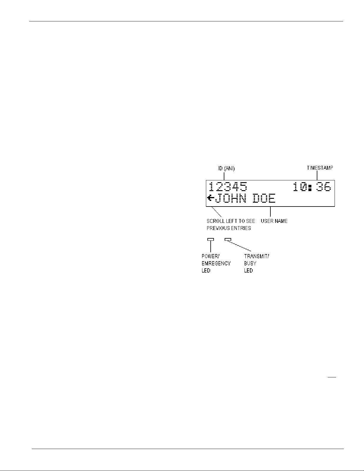
4.1.1 Reading the Display
ID (ANI) – This is the numeric ID (or ANI) of the user
who last transmitted on the channel. When the Status
Feature is enabled, this area will alternate between
displaying the ANI and the status message every 2
seconds.
TIMESTAMP – This is the time of day that the last ANI
was received. The timestamp is in 24-hour format. In
24-hour format, 4 A.M. is displayed as 04:00 and 4
P.M. is displayed as 16:00. Note that the timestamp
changes only when a new ANI comes in, it is not a
time-of-day clock.
3.4 CONFIGURATION SETTINGS
Once adjustments have been made, it will be
necessary to configure the DDU to meet the system
requirements. This is done via Menu Mode. The most
crucial settings include Decode Format and Encode
Format (if using encode feature). Refer to ENC/DEC
SETUP menu item. Pay close attention to Encode
Time 1 & 2 and Decode Time as well.
USER NAME – This is the name of the user
associated with the numeric ID that was received. User
names are stored in a database. The database must
be configured before names can be displayed.
SCROLL LEFT INDICATOR – Indicates that there are
other ANI’s previously logged. Press the left
<SCROLL> button to view the previously logged items.
DDU-100/200 Manual
Page 6
PAGE 6 MIDIAN ELECTRONICS INCORPORATED
POWER / EMERGENCY LED – Glows red when
power is turned on. Blinks between orange to indicate
that an emergency status message was received
recently. This indicator remains blinking until the
operator presses any key.
TRANSMIT / BUSY LED – This LED is off when there
is no activity. It glows red during transmit. It blinks
green any time the radio channel is busy.
4.1.2 Keypad Operation in Display Mode
<SCROLL> LEFT - When in Display Mode, the keypad
<SCROLL> keys are used to scroll through the
previously logged ANI’s. The scroll left indicator
remains present on the screen so long as there are
more previous entries to be viewed. The scroll left
indicator disappears when the oldest entry is reached.
<SCROLL> RIGHT - A scroll right indicator will appear
on the right side of the screen when there are newer
entries available for viewing. Press the right
<SCROLL> button to view the newer entries. When the
last entry is reached, the right scroll indicator
disappears.
<#> POUND KEY – Repeatedly pressing the <#> key
will always return the DDU to display mode with the
last ANI received being shown.
menu mode). Upon selection, the name of the item will
appear on the top line of the display. The bottom line
will present additional items for selection. Press the
<#> key to return to the previous selection.
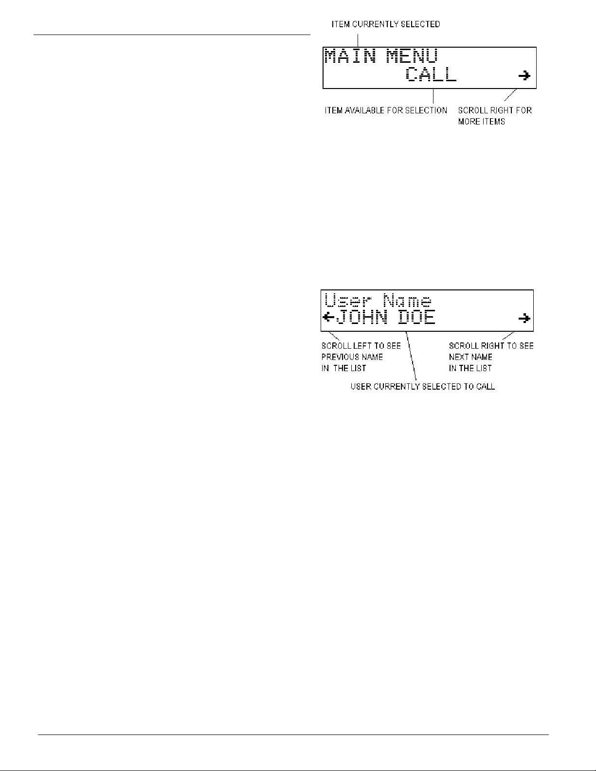
4.2.2 Calling a Unit in the Database
To place a call to a unit in the database, first select
CALL from the Main Menu. Press the right <SCROLL>
button to display the first user in the database. Either
the User ID will be displayed, or the User Name (alias)
will be displayed. This is determined by the Call Entry
Mode setting.
<MONITOR> - This button always controls the monitor
function of the radio. Press <MONITOR> to toggle the
state of the monitor output to the radio.
<SEND> - Activates the radio PTT switch, placing the
radio in transmit mode. This is especially useful if your
DDU is equipped with an optional gooseneck
microphone.
NUMBER KEYS – Pressing one of the number keys
<0> through <9> causes the DDU to jump directly into
call mode. See Calling a Unit for more information.
<*> STAR KEY – Pressing the <*> will place the DDU
in Menu Mode at the main menu.
4.2 MENU MODE
The Menu Mode provides the ability to place calls to
radio users and configure the DDU.
4.2.1 Navigating the Menus
Press the star key <*> while in Display Mode to place
the unit into Menu Mode. Upon entry to Menu Mode,
you will be in the Main Menu. The top line of the
display indicates this. The bottom line displays an item
available for selection, in this case the CALL
command.
The scroll right symbol on the right side of the display
indicates that additional items are available. Press the
right <SCROLL> button to view the next available item.
The scroll left symbol will then appear, indicating that
the left <SCROLL> button may be used to go back to
the previous item.
To select the displayed item, press the <SEND> button
(the <SEND> button acts like an ENTER key when in
The left and right scroll indicators will appear on the
bottom line. This is the Select Mode. Use the
<SCROLL> keys to locate the desired user within the
database. When the name is located, press the
<SEND> key to place the call. The <#> key may be
used at any time prior to pressing <SEND> to cancel
the call.
To locate a user in the database more quickly, you can
enter one or more of the first few digits/letters of the
User ID/Name prior to pressing the right <SCROLL>
button. The DDU will search the database for users
matching the first few digits/letters.
4.2.3 Calling a Unit Not in the Database
To place a call to a unit which is not in the database,
start by selecting CALL from the Main Menu or by
pressing a number key while in display mode. Instead
of pressing the right <SCROLL> button, simply key the
numeric ID of the user to be called using the keypad.
Press <SEND> to initiate the call. The left <SCROLL>
key may be used as a backspace key to correct any
errors made during entry. The <#> key may be used at
any time prior to pressing <SEND> to cancel the call.
4.2.4 Numeric vs. Alphanumeric Entry
There are two different data entry modes available on
the DDU. As shipped from the factory, Numeric entry
is the default mode when calling a unit. As numbers
are entered, they appear on the bottom-left of the
DDU-100/200 Manual
Page 7

MIDIAN ELECTRONICS INCORPORATED PAGE 7
display. Pressing the <*> key while in numeric entry
mode changes the mode to Alphanumeric.
In alphanumeric mode, you may type in letters and
numbers as described in the next section. This allows
you to type the name of a user in the database without
having to scroll through the names. Alphanumeric data
appears on the bottom line of the display as it is
entered. You may make alphanumeric call entry the
default mode by changing the Call Entry Mode setting
in the CONSOLE SETUP menu.
4.2.5 Entering Alphanumeric Data
Entering alphabetic characters using the numeric
keypad is easy. All of the letters of the alphabet appear
above the numbers on the keypad. For example, the
letters ‘A’ ‘B’ and ‘C’ appear on the <2> key.
Alphabetic characters are entered by pressing 2 digits.
The first digit is the key with the desired letter
appearing on it. The 2
on that key. For example, the code for the letter ‘C’ is
23 since it is the 3
is the 1
st
letter on the <8> key, so its code is 81.
nd
digit is the position of the letter
rd
letter on the <2> key. The letter ‘T’
To enter numeric characters in an alphanumeric field,
press the <0> key followed by the desired digit.
Punctuation characters such as comma <,> and <-> do
not appear on the keypad. Special codes have been
assigned to allow entry of those characters. Please
refer to the following chart
Note: Alphanumeric mode cannot be used to enter
user ID's (ANI's). In alphanumeric mode, numbers are
treated the same as letters.
A=21 I=43 Q=72 Y=93 7=07 - =15
B=22 J=51 R=73 Z=94 8=08 = =16
C=23 K=52 S=74 1=01 9=09 * =17
D=31 L=53 T=81 2=02 0=00 / =18
E=32 M=61 U=82 3=03 , =11 # =19
F=33 N=62 V=83 4=04 . =12 Spc=10
G=41 O=63 W=91 5=05 _=13
H=42 P=71 X=92 6=06 +=14
The code 10 is used to insert a space between
characters.
4.2.6 Entering Special DTMF Digits
The DDU supports the following special DTMF 'digits'
in numeric entry mode: *, #, A, B, and C (D is not
supported). These are entered using 2-key sequences
as follows:
* = * * # = * # A = * 1 B = * 2 C = * 3
These special digits can only be entered when adding
a User ID to the database. They cannot be dialed
directly from the CALL menu. Also, these special
sequences should not be used unless you are using
DTMF as the encode or decode format.
4.2.7 Locking and Unlocking the Menus
The menu system incorporates a lock feature to
prevent unauthorized personnel from changing the
DDU configuration. The lock feature also serves to
simplify day-to-day operation of the unit.
When the LOCK command is selected, all of the
menus are disabled. The only items available will be
CALL and UNLOCK. Selecting UNLOCK makes all of
the menu items available again.
When locked, the unit is password protected so only
authorized personnel may unlock the menus. As
shipped from the factory, the security feature is
disabled and the LOCK/UNLOCK options do not
appear. To enable the feature and select a password,
see the SECURITY SETUP menu item.
Remember your password! Once security is enabled
and the menus are locked, the only way to unlock will
be to use the password. If you do forget the password,
contact Midian for the reset procedure.
4.2.8 Repeater Access Control
The DDU can be interfaced to a repeater to limit
access only to those users who are authorized. This is
accomplished by requiring an ANI of the proper format
before granting access. Access can be further
restricted by requiring that the ANI match a User ID
stored in the database. See REPEATER SETUP for
more information.
4.3 USER DATABASE
The user database makes day-to-day operation of the
DDU much easier. You can use easy-to-remember
names instead of just numbers.
4.3.1 User Database Features
The primary purpose of the user database is to
associate names with numbers. This way, when an
ANI comes in, the name of the person can be
displayed along with the ANI. Having a user database
simplifies the calling of units allowing you to scroll
through a list of names.
Another feature of the database is the ability to assign
Kill and Spy ID’s to a user. These features are
designed to work with Midian’s encoder/decoder
products such as the UED-1 series. They allow the
operator of the DDU to disable a radio in the field or
listen in on it.
The DDU can store up to 137 names and ID numbers
in its database. The DDU retains the database memory
even when switched off.
4.3.2 Setting Up the User Database
Begin by compiling a list of names and ID numbers.
DDU-100/200 Manual
Page 8

PAGE 8 MIDIAN ELECTRONICS INCORPORATED
Give some thought on how you are going to abbreviate
the names since only 14 characters per name are
available. To begin entering data, select Add User
from the USERS menu. See the description of these
items in the USERS menu section for more
information.
4.4 STATUS DISPLAY FEATURE
4.4.1 How Status Display Works
The status display feature treats the last digit of an ANI
as a status digit. This digit can be translated to a
status message that can be displayed on the DDU. Up
to 10 status messages can be configured,
corresponding to the digits 0-9.
Say for example that the ANI of a particular unit is
1234X where X is the status digit. If you are running a
taxi fleet, you may wish to specify status information as
follows:
CODE STATUS MSG MEANING
12340 <blank> Normal ANI, no status
12341 OFF DUTY Off duty, not available
12342 ON DUTY On duty
12343 FLAG UP Beginning fare
12344 FLAG DN End of fare
12345 EN ROUTE En-route to pickup fare
12346 NO FARE Nobody at pickup location
12347 REPEAT Repeat last call
12348 BREAKDOWN Car broke down
12349 EMERGENCY Emergency, need help
You can configure the status messages as you see fit
using the STATUS SETUP features. If the Emerg
Status feature is turned on, the status digit 9 is used
for emergency ANI. This will cause the emergency
LED to blink and an alarm siren to sound (if enabled).
Status messages are not displayed by default, this
must be enabled via the STATUS SETUP menu. When
the Status Feature is enabled the last digit of the ANI
is automatically blanked out. Instead, the ANI and the
status message are placed on the 1
display, alternating every 2 seconds.
st
line of the
enter the numeric ID of the unit you wish to call. If the
user database is set up, you may use the right
<SCROLL> buttons to go into Select Mode and find
the name of the user to be called using the left and
right <SCROLL> keys.
Alternatively, you can enter the User ID or User name
in part or in whole. When entering the complete name
or ID, simply press <SEND> to place the call. When
entering a partial name or ID, press the right
<SCROLL> button and find the user you wish to call.
Remember, you can use the <*> to toggle between
numeric and alphabetic entry modes.
5.2 LOCK OR UNLOCK COMMAND
Note The LOCK and UNLOCK menu options do not
appear unless enabled in SECUIRTY SETUP.
Selecting LOCK will disable access to the parts of the
menu system described in the following sections.
Select UNLOCK to enable the entire menu system.
You must enter a 4-digit password to unlock the menu
system. See SECURITY SETUP for more information.
5.3 ACTIONS MENU
5.3.1 Spy command
Allows you to remotely key up and listen to a unit. This
feature is designed to work with Midian’s UED-1 series
encoder/decoders. The code for spying on a unit must
be in the user database to use this function.
5.3.2 Kill command
Allows you to remotely disable a unit. This feature is
designed to work with Midian’s UED-1 series
encoder/decoders. The code for killing a unit must be
in the user database to use this function.
5.3.3 Clear ANI Log command
Allows you to clear the ANI log without having to turn
the unit off and back on.
5.4 USERS MENU
5.4.1 Add User menu
Allows you to add a new user to the database. When
ADD USER is selected, you will be prompted to fill in
the information for that user such as User ID and User
Name. See EDIT USER for more information.
5 MENU SYSTEM
The following sections describe the various functions of
the menu system. Factory default settings are
underlined.
5.1 CALL COMMAND
Allows you to place a call to units equipped with ANI
selective call decoders. You will be given the option to
5.4.2 Delete User menu
Allows you to delete a user record from the database.
When DELETE USER is selected, you will be able to
select the user you wish to delete in the same manner
as if placing a CALL. Use the scroll buttons to find the
user you wish to delete. Press <SEND> to delete the
selected user. You will have to press <SEND> a
second time to confirm. Press <#> to cancel if you
change your mind.
DDU-100/200 Manual
Page 9

MIDIAN ELECTRONICS INCORPORATED PAGE 9
5.4.3 EDIT USER menu
Allows you to change information about a user. Select
the user you wish to edit in the same manner is if
placing a CALL to that user. Use the scroll buttons to
find the user you wish to edit. Press <SEND> to edit
the information for the selected user.
You will be prompted to fill out each field in turn. After
entering the data for a field, press <SEND> to go on to
the next field. To leave a field unchanged, simply press
<SEND> without entering data.
5.4.3.1 User ID field
This numeric field contains the primary ANI number
assigned to the user’s radio. This will be the number
used when calling a unit. ID’s may be 1 to 8 digits
depending on the ANI format used.
Range: 0-8 digits
Default: blank
5.4.3.2 User Name field
This alphanumeric field contains the name of the user
associated with the user ID. A maximum of 14
characters may be used. See the Entering
Alphanumeric Data section for more information.
Range: 0-14 characters
Default: blank
5.4.3.3 Spy ID setting
Specify the code required to spy on this unit. Leave
blank if not using this feature.
Range: 0-8 digits
Default: blank
5.4.3.4 Kill ID setting
Specify the code required to disable this unit. Leave
blank if not using this feature.
Range: 0-8 digits
Default: blank
5.5 SETUP MENU
5.5.1 SOUNDS SETUP menu
5.5.1.1 Keypad Beep option
Turning this option on causes a beep to be heard for
each key press.
OFF Keypad beeps off.
ON Keypad beeps on.
5.5.1.2 Beep On ANI option
Turning this option on will cause an alert beep to be
heard every time a new ANI is received.
OFF Do not beep when ANI comes in.
ON Beep when ANI comes in.
5.5.1.3 Emerg Siren option
This causes a siren sound to be heard when an
emergency ANI is received. This requires turning on
the Emerg Status option in the STATUS SETUP
menu.
OFF Do not sound siren on emergency ANI.
ON Sound siren on emergency ANI.
5.5.1.4 Internal Speaker setting
Normally, the internal speaker is on. This is required in
order for key beeps, error beeps, confirmation beeps,
and other system sounds to be heard. This also allows
audio received from the radio to be heard at the
console. If it is desired that absolutely no sound be
heard from the console speaker, this setting allows it to
be switched off.
OFF Internal speaker disabled.
ON Internal speaker enabled.
5.5.1.5 Auto Mute Speaker feature
This feature is designed to mute the internal speaker
while an ANI is being received. It works in conjunction
with the Auto Mute Time in the RADIO SETUP menu.
When this feature is enabled, the internal speaker
remains muted so long as there is no COR indication
coming from the radio. When the COR indication goes
active, the internal speaker will automatically unmute
after the Auto Mute Time expires. Note: System
sounds can still be heard during the mute period.
OFF Do not mute the internal speaker.
ON Mute/unmute speaker automatically.
5.5.2 TIME SETUP menu
In order for the correct time to be displayed, the time
clock must be set. The unit must remain switched-on
at all times in order to keep track of the time. The clock
must be set each time the unit is powered up.
5.5.2.1 Hour setting
Set the hour of the day in 24-hour format. Enter two
digits.
Range: 00-23
Default: 00
5.5.2.2 Minute setting
Set the minutes past the hour. Enter two digits.
Range: 00-59
Default: 00
5.5.3 CONSOLE SETUP menu
5.5.3.1 Call Entry Mode setting
Determines if numeric entry or alphanumeric data entry
is the default mode when placing a call. The mode of
entry can be toggled by pressing the <*> key during
DDU-100/200 Manual
Page 10

PAGE 10 MIDIAN ELECTRONICS INCORPORATED
data entry (except when entering ANI's).
NUMERIC Start in numeric only mode.
ALPHA Start entry in alphanumeric mode.
5.5.3.2 Fast Scrolling setting
Fast Scrolling allows for faster navigation through the
menu system. The DDU can also animate the scrolling
of the screen from side-to-side. This provides positive
feedback in response to scrolling through menus and
the ANI log. If this effect is desired, Fast Scrolling can
be disabled.
OFF Animate scrolling from side to side.
ON Scroll at fast speed.
5.5.3.3 Contrast setting
Allows the display contrast to be adjusted for best
viewing.
LOW Low contrast setting.
HIGH High contrast setting.
5.5.3.4 Mic. Option setting
Selects which type of optional microphone accessory is
attached to the DDU. This is necessary so that the
DDU knows how to treat the external (for exmpale offhook or monitor).
NONE No microphone.
GOOSENECK Gooseneck style microphone.
PADDLE Paddle style desktop microphone.
HANDSET External handset.
5.5.3.5 Printer Option
The DDU, if ordered with the printer cable option, can
log the ANI traffic to a serial printer. The printer must
have a print buffer and a standard RS-232 port. It must
be configured for 9600 baud, 8 data bits, 1 stop bit and
no parity. In order to send data to the printer, this
option must be on.
OFF Do not send data to printer.
ON Send data to printer.
Default: 0000
5.5.5 RADIO SETUP menu
5.5.5.1 Keyup Delay setting
This sets the Key-Up Delay, also known as Front
Porch Time. This is the amount of time the DDU will
wait after asserting PTT before sending tones over the
air. This time allows for delays introduced by repeaters
and decoding of squelch control signals such as
CTCSS.
Range: 0005 to 4000 milliseconds
Default: 0400 milliseconds
5.5.5.2 COR Polarity setting
Determines which state of the COR (carrier detect)
input is considered the active state. When COR is
active, the radio channel is busy. Important Note: The
DDU will not decode 5-tone formats unless the COR
input is active. If not connecting the COR Input to the
DDU, this setting should be HIGH. If the radio is using
PL/CTCSS, it is recommended that the COR Input be
connected to a point which goes active when PL is
detected.
The COR input is used in conjunction with the Busy
Lockout feature. If not connecting the COR input, do
not enable Busy Lockout .
LOW Channel is busy when COR is 0V.
HIGH Channel is busy when COR is 5V.
5.5.5.3 Busy Lockout option
This option prevents the DDU from transmitting on a
busy channel. If this option is ON, the unit will not
transmit when the COR input is in the active state.
When making a call and the channel is busy, the DDU
will wait until the channel is clear and then transmit.
New calls cannot be placed until the pending call is
completed or canceled. When this option is OFF, the
unit will transmit regardless of the state of the COR
input.
OFF Transmit regardless of COR input.
5.5.4 SECURITY SETUP menu
5.5.4.1 Security setting
Allows the security option to be turned on and off. If
turned off, the LOCK/UNLOCK menus will not appear.
ON Enable security feature.
OFF Disable security feature.
5.5.4.2 Password setting
Sets the password required to UNLOCK the menu
system when the Security is turned on. Must be 4
numeric digits.
ON Do not transmit when channel busy.
5.5.5.4 Squelch Polarity setting
Determines the active state of the Squelch Output. The
Squelch Output is used in conjunction with the COR
Input and the Auto Mute Time to mute incoming ANI
packets.
LOW Radio is squelched when the Squelch
Output. Is brought to GND.
HIGH Radio is squelched when the Squelch
Output is not at GND (floating).
5.5.5.5 Auto Mute Time setting
Range: 4 digits
Specifies the amount of time after the COR Input
DDU-100/200 Manual
Page 11

MIDIAN ELECTRONICS INCORPORATED PAGE 11
becomes active for the Squelch Output to go inactive.
This allows the Squelch Output to be used to mute
incoming ANI's if connected to a point which disables
the radio speaker. This value should be set to allow for
any key-up delay of the transmitting unit as well as the
time it takes for the ANI to complete.
Range: 0000 to 4000 milliseconds
Default: 0300 milliseconds
5.5.5.6 Trunk Delay Polarity setting
When using with trunked radios, this setting
determines the active state of the Trunking Delay Input
(a.k.a. LTR in). This input is used to hold-off
transmitting a call until a channel is acquired on the
trunking system. If a channel is not acquired within 4.5
seconds, a timeout will occur and the call will be
canceled. Important note: The Trunking Delay Input
shares the same wire as the Squelch Output. Normally
the wire acts as the Squelch Output. The DDU must be
jumpered correctly to configure this wire for trunking.
Please see the installation instructions.
When not using the Trunking Delay Input, this setting
should be HIGH.
LOW Trunking signal goes to 0V when a
channel is acquired.
HIGH Trunking signal goes to 5V when a
channel is acquired.
Range: 0005 to 1000 milliseconds
Default: 0050 milliseconds
5.5.6.3 Encode Time 2 setting
When using 5-tone formats (non-DTMF): This is the
duration of each of the remaining tones (or digits) of
the encode sequence. Normally, this should be the
same as Encode Time 1.
When using DTMF format: This is the tone OFF time
(between digits) when using DTMF format.
Range: 0005 to 1000 milliseconds
Default: 0050 milliseconds
5.5.6.4 Decode Format setting
The tone-signaling format of the incoming ANI's. The
Encode and Decode formats may be different if
desired. Select from one of the following formats:
DTMF
CCIR
EEA
EIA
ZVEI
DZVEI
DDZVEI
5.5.6 ENC/DEC SETUP menu
5.5.6.1 Encode Format setting
The tone-signaling format used to encode outgoing
calls. Select from one of the following formats:
DTMF
CCIR
EEA
EIA
ZVEI
DZVEI
DDZVEI
NATEL
MODAT
5.5.6.2 Encode Time 1 setting
When using 5-tone formats (non-DTMF): The
amount of time for the first tone (or digit) of the encode
sequence (may also be a preamble). This is also
known as tone width. Each ANI format has standard
tone widths. Non-standard tone widths are permitted,
allowing for faster encode.
When using DTMF format: This is the tone ON time
for DTMF format.
NATEL
MODAT
5.5.6.5 Decode Time setting
When using 5-tone formats (non-DTMF): The
minimum amount of time a single tone must be present
before it is decoded. This time can be as little as 5
milliseconds. This time should be set between 1/2 and
th
of the encode timing. For example, if the encode
1/5
timing is 50 milliseconds per digit, then the Decode
Time should be set between 5 and 25 milliseconds.
The lower the number, the more sensitive the unit will
be. When the number is higher, the unit will be less
susceptible to falsing on noise.
When using DTMF fo rmat: The amount of time after
the last digit is received for decode to take place. This
value should be at least twice that of the digit OFF
time.
Range: 0005 to 9999 milliseconds
Default: 1000 milliseconds
5.5.6.6 Ignore Nonuser option
Turning on this option helps prevent the display of false
decodes by ignoring ID’s which do not appear in the
user database. This can also be used to restrict access
to a repeater to only those ID’s in the database. See
REPEATER SETUP for more information.
OFF Display ID’s not in database.
DDU-100/200 Manual
Page 12

PAGE 12 MIDIAN ELECTRONICS INCORPORATED
ON Ignore ID’s not in database.
5.5.7 REPEATER SETUP menu
5.5.7.1 Repeat Control option
Allows the DDU to control access to a repeater.
Causes the DDU to assert a PTT ou tput to a repeater
upon receipt of either: (1) any ANI in the format
decoded by the DDU or (2) a valid User ID in the user
database. To restrict repeater access to valid User ID’s
only, the Ignore Nonuser option in the ENC/DEC
SETUP must be turned ON. Otherwise, any incoming
ANI of the proper format will be considered valid.
Other possible uses of the Repeat Control option
include operation of a horn relay or the enabling of a
PA speaker. Repeater control output can either be the
PTT output, or the MONITOR output (see below).
OFF Repeater control disabled.
ON Repeater control is enabled.
5.5.7.2 Validate Time setting
This sets how long after COR becomes active, that the
repeater will be keyed prior to receiving a valid decode.
This allows time for the incoming ANI to be broadcast
by the repeater before it has been validated. If no ANI
(or valid User ID) has been decoded during this time,
the repeater will be un-keyed. The repeater will remain
un-keyed until COR goes inactive.
If set to 0, the repeater will not be keyed until after the
ANI (or valid User ID) has been decoded.
Range: 00 to 99 10ths of a second (0.0 - 9.9 s)
Default: 10 10ths of a second (1.0 second)
5.5.7.3 PTT Hang Time setting
Once validation has occurred, this sets how long the
repeater will remain keyed after COR goes inactive.
Once the hang timer expires, a new validation will be
required to access the repeater.
Range: 00 to 99 10ths of a second (0.0 - 9.9 s)
Default: 20 10ths of a second (2.0 seconds)
5.5.7.4 Hang Reset setting
This setting specifies what is required to reset the PTT
hang timer before it expires. This can either be COR
or COR+ANI. When set to COR, the hang timer will be
reset if COR goes active prior to expiration, allowing
the conversation to continue without a new validation.
When set to COR+ANI, a new valid ANI will also be
required to keep the repeater open.
COR Reset hang timer if COR goes active
before the hang time expires.
COR+ANI Require both COR and an ANI (or
valid User ID) to reset the hang timer
before expiration.
5.5.7.5 Repeater Out setting
This setting specifies which output is used to put the
repeater into transmit mode when Repeat Control is
enabled.
PTT PTT output used to key repeater in
Repeat Control mode.
MONITOR MONITOR output used to key repeater
in Repeat Control mode.
5.5.8 STATUS SETUP menu
5.5.8.1 Status Feature option
When enabled, the Status Feature always treats the
last digit of an incoming ANI as a status digit. The last
digit of the ANI is not actually displayed. Instead the
user's ANI and Status Message are displayed
alternately (every 2 seconds).
When the Status Feature is enabled, it will be required
that all units send an extra digit after their ANI. See the
section on Status Display Feature for more
information.
OFF Disable status feature.
ON Enable status feature.
5.5.8.2 Emergency Status option
When enabled, the Emergency Status option treats
any ANI with 9 as the last digit as an Emergency ANI.
When an Emergency ANI comes in, the PWR-ALM
LED flashes rapidly between green and orange.
Optionally, the Emerg Siren sound can be enabled to
alert the system operator of the emergency situation.
The Emergency Status option may be used alone, or in
conjunction with the Status Feature option. When
used alone, the digit '9' will appear and the status
message is not displayed. Also, the User Name in the
database will not be properly displayed.
When used in conjunction with the Status Feature, the
'9' will not be displayed. Instead, Status 9 Msg will be
displayed (unless it is blank), alternating with the ANI.
The User Name in the database will be properly
displayed.
OFF Display ID’s not in database.
ON Ignore ID’s not in database.
5.5.8.3 Status 0 Msg setting
Allows you to specify the status message displayed
when using the Status Feature. When using this
feature, the last digit of the ANI will be used to
determine the status. There is a status message for
each of the digits 0 through 9. Each status message
may be up to 10 alphanumeric characters.
Range: 0-10 characters
Default: blank
DDU-100/200 Manual
Page 13

MIDIAN ELECTRONICS INCORPORATED PAGE 13
5.5.8.4 Status 1 Msg setting
See Status 0 Msg setting above.
Range: 0-10 characters
Default: blank
5.5.8.5 Status 2 Msg setting
See Status 0 Msg setting above.
Range: 0-10 characters
Default: blank
5.5.8.6 Status 3 Msg setting
See Status 0 Msg setting above.
Range: 0-10 characters
Default: blank
5.5.8.7 Status 4 Msg setting
See Status 0 Msg setting above.
Range: 0-10 characters
Default: blank
5.5.8.8 Status 5 Msg setting
See Status 0 Msg setting above.
database will not be affected.
5.5.9.2 Clear Database
This will clear the user database of all ID's and User
Names. The contents of the other parameters listed
above will not be affected.
5.5.9.3 Factory Debug
This is used by the factory for product testing. Do not
select this function unless directed to do so by
Midian Technical Support. Damage to the unit may
result.
Range: 0-10 characters
Default: blank
5.5.8.9 Status 6 Msg setting
See Status 0 Msg setting above.
Range: 0-10 characters
Default: blank
5.5.8.10 Status 7 Msg setting
See Status 0 Msg setting above.
Range: 0-10 characters
Default: blank
5.5.8.11 Status 8 Msg setting
See Status 0 Msg setting above.
Range: 0-10 characters
Default: blank
5.5.8.12 Status 9 Msg setting
See Status 0 Msg setting above. Note that this status
message is associated with emergency status.
Range: 0-10 characters
Default: blank
5.5.9 UTILITIES menu
5.5.9.1 Reset Defaults
This will reset all the parameters listed above to the
factory default settings. The contents of the user
DDU-100/200 Manual
Page 14

PAGE 14 MIDIAN ELECTRONICS INCORPORATED
6 SYSTEM ERROR MESSAGES
CHANNEL BUSY
Reason: An attempt was made to transmit or make a
call on a busy channel with busy lockout enabled.
Solution: Wait until the channel is clear before
transmitting.
DATABASE EMPTY
Reason: An attempt was made to edit or delete a user
when the database was empty.
Solution: These functions do not apply when the
database is empty.
DATABASE FULL
Reason: An attempt was made to add a user to the
database and there is no more room. The maximum
number of user aliases of 137 cannot be exceeded.
Solution: Remove any old user names that are no
longer in service. If this is not possible, contact Midian
to learn about our Computer Aided Dispatch (CAD)
fleet management systems which can handle many
more users.
DATABASE ERROR
Reason: One or more entries in the user database has
been corrupted. This can happen if power is lost at the
exact time the database is being updated. Any
corrupted records will be blanked-out and must be reentered.
Solution: Cycle power to the unit. This should clear the
error. If the error message continues to come up,
contact Midian technical support.
DUPLICATE ID
Reason: An attempt was made to add a user ID to the
database which is already in the database. Each user
ID in the database must be unique.
Solution: Choose a unique user ID for each user. If it is
necessary to edit the user record, use the edit menu.
EE CHKSUM ERR
Reason: The configuration settings stored in EEPROM
have been corrupted. This can happen if power is lost
at the exact time a parameter is being updated. All
configuration settings will be set back to defaults. The
user database should not be affected.
Solution: Cycle power to the unit. This should clear the
error. If the error message continues to come up,
contact Midian technical support.
EE WRITE FAIL
Reason: The EEPROM chip or connections to it have
failed.
Solution: Contact Midian for instructions on getting the
unit repaired.
FIELD IS BLANK
Reason: An attempt was made to place a call, but the
user ID or name was blank. An a ttempt was made to
spy or kill and the respective field in the database is
blank.
Solution: When placing a call, be sure an ID number or
user name is displayed before pr essing <SEND>. The
spy and kill functions require there be an entry in the
respective field of the user database.
MODEM TIMEOUT
Reason: The DDU expects a call to be completed
within 4.5 seconds and this time has been exceeded.
This can happen if the total of the key-up delay and
tone widths exceed 4.5 seconds. This can also happen
when used in a trunking system and a channel cannot
be acquired. It is also possible that there could be a
hardware failure.
Solution: If total time of the key-up delay and signaling
tones exceeds 4.5 seconds, simply press <SEND> to
clear the message from the display. The call will still be
sent. If the timeout is caused by excessive channel
acquisition time in a trunking system, press <SEND> to
clear the error and try placing the call again. In the
event of a hardware failure, contact Midian technical
support to determine if that is the cause.
NOT FO
eason: There is no entry in the user database that
R
matches the data entered.
Solution: When selecting a user to call, the name or
the ID can be entered in whole or in part. When
entering a partial name or ID, press the right
<SCROLL> button to search the database for the first
partial match. Press <SEND> only if the whole ID or
name has been entered. There may be no entry in the
database that matches in whole or in part. In that case,
the user must be added to the database.
UND
DDU-100/200 Manual
Page 15

MIDIAN ELECTRONICS INCORPORATED PAGE 15
7 MENU SYSTEM MAP
DDU-100/200 Manual
Page 16

1
1
2
2
3
3
4
4
5
5
6
6
D D
C C
B B
A A
-
+
2
3
1
4 8
LM358
U3:1
-
+
6
5
7
LM358
U3:2
VAN
VAN
TP1
TP5
TP8
2 3
A6
D1:1
13
A6
D1:2
Q1
11
Q2
12
Q4
14
Q3
13
IN+
1
GS
3
VRef
4
INH
5
ESt
16
IN-
2
PWDN
6
StD
15
OSC2
8
OSC1
7
TOE
10
VSS
9
St/GT
17
VDD
18
MT8870
U11
+5V
+5V
-
+
2
3
1
411
LM324
U4:1
-
+
6
5
7
LM324
U4:2
-
+
9
10
8
LM324
U4:3
-
+
13
12
14
LM324
U4:4
+5V
TP2
TP3
+5V
+5V
-
+
2
3
1
411
*
U5:1
-
+
6
5
7
*
U5:2
-
+
9
10
8
*
U5:3
-
+
13
12
14
*
U5:4
+5V
VAN
VAN
2
1
3
147
*
U10:1
5
6
4
*
U10:2
8
9
10
*
U10:3
12
13
11
*
U10:4
R1
11
R2
12
SIGin
14
COMPin
3
VCOout
4
INH
5
VCC
16
PC1out
2
C1A
6
GND
8
C1B
7
VCOin
9
*
U8
+5V
+5V
+5V
CPA
1
CPA
2
2A
5
3A
6
MRA
7
VCC
16
GND
8
*
U7:1
1B
12
0B
11
CPB9CPB
10
2B
13
3B
14
MRB
15
*
U7:2
+5V
+5V
11
33
22
100K
R26
11
33
22
100K
R28
VAN
+5V
TP4
+5V
XTAL
1
TX OUT
4
TXD IN
5
TX EN
6
VBIAS
9
VSS
10
CKD
12
CD
13
RX IN
14
RX SYNC
15
1200/2400
16
4800
17
CLK RATE
18
CDRC
19
VDD
20
*
U9
+5V
+5V
+5V
+
*
C77
+5V
+
*
C34
C
+5V
2 3
A6
D6:1
13
A6
D6:2
+5V
B25
Q1
+5V
T1_IN
11
R1_OUT
12
T1_OUT
14
R1_IN
13
C1+
1
C1-
3
C2+
4
C2-
5
VCC
16
V+
2
V-
6
GND
15
MAX232A
U16
+5V
OSC2
42
TCAP
41
D7
39
OSC1
43
A5
7
A6
6
A7
5
A4
8
A3
9
A1
11
A0
12
C4
27
C1
30
C6
25GND
22
TCMP
38
IRQ
2
VDD
44
VPP
4
SS
37
B3
16
B0
13
B1
14
A2
10
C5
26
C3
28
C0
31
C2
29
C7
24
B4
17
B7
21
B6
20
RES
1
B2
15
B5
19
SCK
36
MOSI
35
MISO
34
RDI
32
TDO
33
NC4
3
NC1
18
NC2
23
NC3
40
68705C9
U2
P4B:1
P4B:2
P4B:3
BSS
Q2
+5V
PRINTER
N/C
1
VDD
2
CS
3
SK
4
N/C
8
VSS
7
SO
6
SI
5
CAT93C46
U12
+5V
4001
D5
4001
D4
+
470u
C76
5 4
SW1
PWR/VOL
11
33
22
R5
10K
+VIN
OUT
1
SENSE2SHDN
3
GND
4
ERR
5
VTAP
6
FDBK
7
IN
8
MIC2951
VR1
OUT
1
SENSE
2
SHDN
3
GND
4
ERR
5
VTAP
6
FDBK
7
IN
8
MIC2951
VR2
+
1u
C48
+
1u
C54
+5V
-
+
2
3
1
411
LM324
U6:1
-
+
6
5
7
LM324
U6:2
-
+
9
10
8
LM324
U6:3
-
+
13
12
14
LM324
U6:4
+
1u
C52
VAN
SOURCE
+5VLCD
+5V
BSS
Q3
2 3
A6
D2:1
1 3
A6
D2:2
B25
Q4
P6:1
P6:2
P6:3
P6:4
P6:5
COL1
P6:6
COL2
P6:7
COL3
P6:8
COL4
P6:9
ROW1
P6:10
ROW2
P6:11
ROW3
P6:12
ROW4
P6:13
+5V
CTR
P7:1
P7:2
P7:3
P7:4
P7:5
P7:6
DB5
P7:7
DB6
P7:8
DB7
P7:9
DB4
P7:10EP7:11
R/W
P7:12RSP7:13
+5V
+5V
+5VLCD
CS
1
SO
2WP
3
VSS
4
VCC
8
HOLD
7
SCK
6
SI
5
25C320
U13
+5V
+5V
4.032 MHz
Y1
A11A
11
X012X0
12
X113X1
13
X14X
14
74HC4053
U15:1
B10B
10
Y11Y1
1
Y02Y0
2
Y15Y
15
74HC4053
U15:2
C9C
9
Z4Z
4
Z05Z0
5
Z13Z1
3
E\6E\
6
VCC16VCC
16
VEE7VEE
7
GND8GND
8
74HC4053
U15:3
TP7
TP6
VAN
C
1 2
)
JU1
2
__
3
++
5
64
17
BYPBYP
8
LM386
U14
+VIN
B25
Q5
+
47u
C45
2
1
INTERNAL SPEAKER
P5
+5V
+
47u
C40
B25
Q6
+VIN
+5V
VAN
11
33
22
100K
R51
+
2.2u
C46
27K
R81
12
)
JU4
11
33
22
100K
R105
VAN
+
4.7u
C36
1
2
MIC
P2
10K
R1
10K
R38
.022u
C1
.022u
C27
100p
C30
100p
C4
10K
R37
10K
R14
.01u
C6
470K
R6
1M
R7
1M
R8
470K
R9
*
JU2
0R
JU3
10K
R441M
R15
10K
R109
10K
R49
200K
R17
7.5K
R110
.01u
C73
.001u
C14
39K
R91
100p
C16
100K
R13
.022u
C13
15K
R16
560p
C65
200K
R11
10K
R10
.01u
C15
10K
R18
7.5K
R19
.01u
C17
.01u
C18
27K
R20
1M
R21
150K
R22
.001u
C19
.0022uC21
.0022u
C22
82K
R30
4.7K
R31
470K
R27
27K
R29
10K
R12
.047u
C20
.0047u
C24
15K
R23
240K
R24
240K
R25
.001u
C25
*
JU8
*JU6
*
JU7
.1u
C29
100K
R41
47K
R40B
*
R40A
2.7K
R39
10K
R59
20K
R58
10K
R61
20K
R60
10K
R63
20K
R62
10K
R65
20K
R64
10K
R67
20K
R66
10K
R69
20K
R68
10K
R71
20K
R70
20K
R72
20K
R73
.01u
C58
47K
R93
47K
R102
47K
R106
10K
R111
*
JU5
0R
R85
10K
R88
4.7K
R94
+
4.7u
C53
10K
R87
7.5K
R86
560p
C54A
.01u
C12
*
C48A
+
1u
C55
560p
C60
.47u
C56
560p
C2
560p
C3
4.7K
R83
47K
R103
22p
C8
22p
C9
4.7M
R55
+
1u
C51A
560p
C51
47K
R107
.1u
C64
.1u
C50
.1u
C49
4.7K
R36
560p
C26
*
R115
56K
R92
47K
R84
100K
R108
100K
R74
100K
R75
.001u
C42
100p
C41
240K
R76 27K
R89
10K
R112
10K
R90
100p
C66
100p
C67
100p
C68
100p
C69
100p
C70
100p
C71
100p
C72
0R
R95
*
R96
.001u
C57B
.01u
C57A
1K
R78
.001u
C73A
*
C73B
.01u
C38
*
R45
*
C31
22R
R114
22R
R46
47K
R104
4.7K
R33
10K
R52
*
R116
82R
R53
560p
C43
10K
R80
*
C46A
240K
R79
10K
R56
100p
C44
10K
R4
2.2K
R113
.022u
C37
62K
R50
4.7K
R48
7.5K
R47
560p
C39
+5V
+5V
560p
C47
47K
R43
Y25
Q7
47K
R57
+5V
EARPC
MIC
WHT
YEL
BLK
RED
PTT SW
HANDSET
[OPTIONAL]
TILT SW
COR
P1:1
SQ OUT
LTR IN
P1:2
PTT
P1:3
AUDIO OUTPUT
P1:4
+VIN
P1:5
GND
P1:6
MONITOR
P1:7
AUDIO INPUT
LOCAL REMOTE
P1:8
P1:9
P1:10
GOOSE NECK MIC
[OPTIONAL]
EXT PTT IN
SENSE/OFFHOOK & EXT MONITOR
3.58 MHz
Y2
22p
C32
22p
C33
4.7M
R35
+5V
KEYBOARD
LCD
DDU-100DTMF
DDU-2005 TONE
DDU-400
DDU-300
GSTAR FORMAT
ZAP FORMAT
DDU-500/600
FFSK
OPTION
MONITOR OUT
CP
CJS
2012-05-11
DML
2014-03-27
C-2
1 of 1
7749
MIDIAN ELECTRONICS, INC.
DATE:
DESIGN:
DWN BY:
REV:
APPR
COPYRIGHT ©
REV
SHEET
PROJECT NUMBER
DOCUMENT NAME
SCHEMATIC
2014
DDU-100/DDU-200
+5V
*
C52A
*
C78
*
C79
.022u
C28
+
2.2u
C63
.1u
C5
.1u
C7
.1u
C10
.1u
C23
.1u
C35
.1u
C61
.1u
C62
.1u
C74
.1u
C75
JUMPER
R82
C77[1uF] USED ONLY FOR
SPECIFIC PROD DATES OF U9
NOTE
10K
R42
.1u
C59
VAN
+5V
GND
P3:1
BLK
EARPC
P3:2
RED
SENSE/EXT MIC
P3:3
SHLD
GND
P3:4
YEL
MIC IN
P3:5
GND
P3:6
GND
P4:1
BLK
P4:2
RED
P4:3
GRN
P4:4
YEL
P4:5
GND
P4:6
PRINT RDY
PRINT DATA
A
B
B
A
CONNECTS TO
U15:1 & U15:2
MIC SENSITIVITY
OUTPUT LEVEL ADJUST
CONNECTS TO U9
11
33
22
1M
R2
11
33
22
1M
R32
1.5K
R97
5.1V
D7
2
1
3
DCJ
*
RJ1
D
D
CONNECTS
TO RJ1
CONNECTS
TO U1:43
FUSE
OSC2
42
TCAP
41
D7
39
OSC1
43
A5
7
A6
6
A7
5
A4
8
A3
9
A1
11
A0
12
C4
27
C1
30
C6
25
GND
22
TCMP
38
IRQ
2
VDD
44
VPP
4SS37
B3
16
B0
13
B1
14
A2
10
C5
26
C3
28
C0
31
C2
29
C7
24
B4
17
B7
21
B6
20
RES
1
B2
15
B5
19
SCK
36
MOSI
35
MISO
34
RDI
32
TDO
33
NC4
3
NC1
18
NC2
23
NC3
40
MC68HC705C8
U1
PIR7501
COR75
COR108
PIR7502
COTP1
COC1
COP1:8
PIP108
COR1
PIR102
COR38
PIR101
PIR3801
PIR3802
PIC101 PIC102
COC27
PIC2701PIC2702
PIC3001 PIC3002
PIR3202
PIR3203
PIR3201
COR32
PIU306
PIU305
COTP5
COC30
PITP501
COR42
PIR4201 PIR4202
PIU307
COU3:2
PIR201
COC4
PIR202
PIR203
COR2
PIU302
PIU303
PIC401PIC402
COR37
PIU308
PIU301
COU3:1
PIU304
PIR1401
COR14
PIR1402
PIU409
PIU4010
COU4:3
COR10
PIR1002
PIR1001
COR11
PIR1101 PIR1102
PIC1501
COC15
PIC1502
PIU4012
PIC6502
COC65
PIC6501
PIU4013
PIU4014
COU4:4
COR16
PIR1601 PIR1602
COR13
COC13
PIC1801PIC1802
COC18
COC17
COR18
PIR1802
PIR1801
PIC1701PIC1702
PIR1901
COR19
PIR1902
PIU7015
COU7:2
PIU709
PIU7010
PIU10013
PIU10012
COU10:4
PIU7011
PIU7012
PIU7013
PIU7014
PIU10011
COR20
PIR2002
PIU506
PIU505
PIR2001
PIU507
COU5:2
PIR2302
PIR2301
PIC2002
COC20
PIC2001
PIR2402
PIR2401
COR21
PIR2101 PIR2102
PIU502
PIU503
COU10:1
PIU504
COU5:1
PIU5011
PIU1003
COR23
COR24
COC24
PIC2401PIC2402
PIR2501 PIR2502
COR25
COR22
PIU1001
PIU1002
PIU501
PIU10014
PIU1007
PIU5013
PIU5012
PIC2502
COC25
PIC2501
PIC1301PIC1302
PIR2201PIR2202
PIU706
COU5:4
COC28
PIC2801PIC2802
PIR4102
PIR40B02
COR40B
COR39
COP1:1
PIP101
PIR3901
PIR3902
PIR40B01
PIQ10B
PIR40A01
COR40A
PIQ10C
COQ1
PIQ10E
COR41
PIR4101
PIR40A02
PITP101
PIR3701PIR3702
PIU408
PIR1301PIR1302
PIC1601
COC16
PIC1602
PIU1009
PIU1008
PIC1902
COC19
PIC1901
PIU702
PIU7016
PIU707 PIU708
PIU5014
PIJU601 PIJU602
PIJU701 PIJU702
COU7:1
PIC7501
COC75
PIC7502
COJU6
COJU7
COC29
COC6
PIC601
PIC602
COC7
PIC701
PIC702
PIU403
PIU402
COU10:3
PIU404
PIU4011
PIU10010
PIU1005
PIU705
PIU1006
COU10:2
COU5:3
PIU701
PIU509
PIU5010
PIJU801
COJU8
PIJU802
PIC2901
PIC2902
PIC7701
PIC7702
PIC3401
PIC3402
PIR802
COR8
PIR801
PIU401
COU4:1
PIU1004
PIU508
COC77
COC34
COR6
PIR601PIR602
PIR701 PIR702
COD1:1
PID102 PID103
COTP2
PITP201
COD1:2
PID103
COR91
PIR9101
COC14
PIU8014 PIU8016
PIU803
PIU804
COR26
COU9
PIU904
PIU9017
PIU9014
PIU906
PIU9016
PIU9019
PIU909
PIU11010
COR7
COTP8
PITP801
PIU1103
PIU1102
PIU11017
PIR902
COR9
PIR901
PID101
PIR9102
PIC1401
PIC1402
PIU11016
PIU1104
PIU1101
PIU1108
PIR1702
COR17
PIR1701
PIR10902
COR109
PIR10901
PIU405
PIU406
PIR11002
COR110
PIR11001
COC21
PIC2101 PIC2102
COC22
PIC2201 PIC2202
COU8
PIU8011 PIU8012
PIR2601
PIR2602
PIR2603
PIR2802
PIR2702
COR27
PIR2701
PIC6101
PIC6102
PIU9018
PIU9020
PIU9010
PIRJ101 PIRJ102
PIC7302
COC73
PIC7301
PIU806PIU807
PIR2801
COR28
PIR2803
PIR2902
COR29
PIR2901
COC61
PIU9012
PIU9013
PIU9015
PIU905
PIU901
CORJ1
PIU805
PIU11018
COU11
PIU1109
COR15
PIU1105 PIU1106
PIR1501PIR1502
PIU407
COU4:2
PIU808
PIR1201
COR12
COTP4
PITP401
PIR1202
PIU1107
PIU11011
PIU11012
PIU11013
PIU11014
PIU11015
COTP3
PIR4402
PITP301
COR44
PIR4401
PIR4902
COR49
PIR4901
PIU802
PIR3002
COR30
PIR3001
PIU809
PIR3102
COR31
PIR3101
PIC2301
COC23
PIC2302
PIC52A02
PIC52A01
PIU106
PIU108
PIU107
PIU109
PIU1011
PIJU202
COJU2
PIJU201
PIU1012
PIJU301
COJU3
PIJU302
PIU1041
PIU102
PIU1022
PIU1023
PIU1039
PIU1040
PIU1027
PIU1030
PIU1025
PIU1038
PIC5201
COC52A
PIC5202
COC52
COC33
PIC3301
PIC3302
COR35
PIR3502
PIY201PIY202
COY2
PIU1042
COU1
PIU608
COU6:3
COC32
PIC3201PIC3202
PIR3501
PIU1043 PIU1044
PIU105
PIU6010
PIU609
PIC5301
PIC5302
PIU103PIU104
PIU1037
PIU101
COC53
PIR10801 PIR10802
PIC1001
COC10
PIC1002
PIU1031
COR58
PIU1021
COR60
PIU1020
COR62
PIU1019
COR64
PIU1017
PIU1018
COR66
PIU1016
COR68
PIU1015
COR70
PIU1014
COR72
PIU1013
PIU1024
COU12
PIU1028
PIU1036
PIU1035
PIU1034
PIU1204
PIU1205
PIU1206 PIU1207
PIR9301
COR93
PIR9302
PIU1033
PIU1032
PIU1029
PIU1026
PIU1010
PIR8701
COR87
PIC7901
PIC7902
PIR8702
PIR8601
COR86
PIR8602
PIR7401
COR74
PIR7402
COTP6
PITP601
PIR5801PIR5802
PIR5902
COR59
PIR5901
PIR6001PIR6002
PIR6102
COR61
PIR6101
PIR6201PIR6202
PIR6302
COR63
PIR6301
PIR6401PIR6402
PIR6501
COR65
PIR6502
PIR6601PIR6602
PIR6701
COR67
PIR6702
PIR6801PIR6802
PIR6901
COR69
PIR6902
PIR7001PIR7002
PIR7101
COR71
PIR7102
PIR7201PIR7202
PIR7301
COR73
PIR7302
PIR8802
COR88
PIR8801
PIC5401
COC79
PIC5402
PIR9202
PIR9201
PIU1202PIU1203
PIU1208
PIU1201
COC54
COR76
PIR7601 PIR7602
PIC4201
COC42
PIC4202
COR115
PIR11501 PIR11502
COR92
PIC5802
PIC6201
COC62
PIC5801
PIC6202
PIC54A02
COC54A
PIC54A01
PIC4101
COC41
PIC4102
PIU6013
PIU6012
COU15:1
PIU1501
PIU1502
COU15:2
PIU1307
PIU1308
COC58
PIU1303
PIU1304
COU13
PIC1201
COC12
PIC1202
PIC48A02
PIC48A01
PIR8902
PIU6014
COU6:4
PIU15014
PIU15013
PIU15012
PIU15011
PIR8402
COR84
PIR8401
PIU15010
COTP7
PITP701
PIU15015
PIU2038
PIU2044
PIU2037
PIU204
PIU203
PIU2022
PIU2023
PIR10601
COR106
PIR10602
PIU1301
PIU1306
PIU1305
PIU1302
PIU2019
PIU2036
PIU2035
PIU2034
PIR10202
COR102
PIR10201
PIU2032
PIU2033
PIC4801
COC48A
PIC4802
COR89
PIR8901
PIVR201
COC48
PIVR202
PIVR204
COJU1
PIJU101 PIJU102
COU2
PIU202
COVR2
PIVR205
PIR11201
COR112
PIR11202
PIVR203
PIVR208
PIVR207
PIVR206
PIR9001
COR90
PIR9002
PIU2016
PIU2013
PIU2039
PIU2040
PIU205
PIU206
PIU207
PIU208
PIU2010
PIU2011
PIU2012
PIU209
PIU2031
PIU2028
PIU2026
PIU2027
PIU2024
PIU2025
PIU2029
PIU2030
PIU2018
PIU2017
PIU2021
PIU2014
PIU2015
PIU201
PIU2041
PIU2043
PIU2042
PIU2020
PIVR101
PIVR102 PIVR103
PIVR104
COP7:7
COC67
PIP707
PIC6802
COC68
PIC6801
COP7:9
PIP709
PIC6602
PIC6601
COP7:8
PIP708
COC66
PIC6702
PIC6701
PIP6010
COP6:10
PIP6011
COP6:11
PIP6012
COP6:12
PIP6013
COP6:13
PIP606
COP6:6
PIP607
COP6:7
PIP608
COP6:8
PIP609
PIP602
PIP604
PIP605
PIP601
PIP603
COP6:9
COP6:2
COP6:4
COP6:5
COP6:1
COP6:3
COC51
PIR10702
COR107
PIC5102
COC51A
PIC5101
PIC51A01
PIC51A02
PIR10701
PIR5502
COR55
PIR5501
COC9
PIC901 PIC902
PIY101
COY1
PIY102
PIC801 PIC802
COC8
COVR1
PIVR105
PIVR108
PIVR106
PIVR107
COC49
PID702
PID701
PIC4902
PIC4901
PID201 PID203
COD2:1
PID202 PID203
COD7
PIC5501
COC55
PIC5502
COP7:10
PIP7010
PIC6902
COC69
PIC6901
PIC57A02
PIC57A01
COR95
PIU16011
PIU16012
PIU1601
PIU1603
COD2:2
COP7:11
PIP7011
PIC7002
COC70
PIC7001
COC57A
PIR9602
COR96
PIR9601
PIR9501PIR9502
PIR9701
PIR9702
PIU16016
COU16
PIU16015
COP7:12
PIP7012
PIC7102
COC71
PIC7101
PIP705
PIP706
PIC57B02
COC57B
PIC57B01
PIP703
PIP704
PIP702
PIC7802
COC78
PIC7801
PIP701
COR97
COC64
PIC6401PIC6402
PIU1602
PIU1606
PIC5902
PIC5901
COC59
PIR11101
COR111
PIR11102
COR94
PIR9401 PIR9402
COP7:13
PIP7013
PIC7202
COC72
PIC7201
COP7:5
COP7:6
PIR7902
COR79
PIR7901
COP7:3
COP7:4
PIR5602
COP7:2
COR56
PIR5601
COP7:1
COP4B:1
COP4B:2
PIP4B01
PIU16014
PIU16013
PIU1604
PIC5002
COC50
PIC5001
PIU1605
PID602 PID603
COD6:1
COP4B:3
PIP4B02
COD6:2
PID601PID603
PIQ20G
COtb0sch1
COC63
PIC6301 PIC6302
PIU1509
PIU15016
PIU1505
PIU1503
PIP4B03
COJU5
PIJU501PIJU502
PIR8501 PIR8502
PIQ20D
COQ2
PIQ20S
COSW1R5:2
PISW1R503
PISW1R502
PISW1R501
PIR7802
COR78
PIR7801
PIR3301
COR33
PIR3302
COU15:3
PIU1504
PIU1508
PIU1507
PIU1506
COP4:2
PIP402
COP4:5
PIP405
COP4:3
PIP403
COP4:4
PIP404
COP4:1
PIP407
COP4:6
PIP408
COR85
PIC7401
PIC7402
PIC73A02
COC73A
PIC73A01
PIC3801
PIC3802
COR80
PIU602
PIU603
COR113
PIC73B01
COC73B
PIC73B02
PIQ50C
COQ5
PIQ50B
COC38
COC43
PIC4301PIC4302
PIR5101
PIR8001PIR8002
PIU604
PIU601
COU6:1
PIU6011
PIR401 PIR402
PIU607
PIR11301
PIQ50E
PIR5102
PIR5103
COR51
COC44
PIC4401 PIC4402
COR4
COU6:2
PIR11302
PIC5602
PIC5601
COC74
PIU1406
PIU1408
PIU1403
COU14
PIU1402
PIU1404
PIC502
COC5
PIC501
COQ7
COR52
PIQ60B
PIR5201PIR5202
COR116
COC46A
PIC46A01 PIC46A02
PIC4601 PIC4602
COC46
PIR10502
PIR10501
PIR10503
COR105
PIU606
PIU605
COR36
PIR8301 PIR8302
COR83
PIR10301
COR103
PIR10302
PIFUSE01 PIFUSE02
COFUSE
COC60
COC56
COR45
PIR4502
PIU1401
PIU1405
PIU1407
PIQ70E
PIQ70B
PIQ70C
PIR5702
COR57
PIR5701
PIR4501
PIC3101
PIC3102
PIR11402
COR114
PIR4602
PIR11401
PIR4601
PIC3501
PIC3502
COR43
PIR4301PIR4302
COC47
PIR10402
COR104
COC31
PIC4501
COC45
COR46
COC35
PIC4702
PIC4701
PIC4502
PIR10401
PIQ60C
COQ6
PIQ60E
PIR11601
PIR5301
COR53
PIR11602
PIR8102
PIR5302
COJU4
COR81
PIJU401PIJU402
PIR8101
PIC4001
COC40
PIC4002
PIR4702
COR47
PIR4701
PIC3601
PIC3602
COC39
PIC2602
COC26
PIC2601
PIR8202
COC37
PIC3701 PIC3702
PIR3601PIR3602
PIC202
PIC201
PIR5001 PIR5002
PIQ40B
PIQ30G
COC2
COSW1R5:1
PIC6002
PIC6001
COR50
PIQ40C
COQ4
PIQ40E
PIQ30D
COQ3
PIQ30S
PIC301
PIC302
PISW1R504PISW1R505
PIC7601
PIC7602
PIR4801
COR48
PIR4802
PIC3901
PIC3902
COC3
COR82
PIR8201
COC76
PIP305
PIP303
COP3:4
PIP304
PIP302
PIP307
PIP308
COC36
COD4
PID502
COD5
PID501
COP3:5
COP3:3
COP3:2
COP3:1
COP3:6
PID401PID402
COP5
PIP501
PIP502
PIP104
COP1:4
PIP201
PIP202
PIP107
COP2
COP1:7
COP1:3
PIP103
COP1:2
PIP102
COP1:5
PIP105
PIDCJ01
PIDCJ03
PIDCJ02
PIP106
PIP109
PIP1010
CODCJ
COP1:6
COP1:9
COP1:10
Page 17

COVO1
PAVO104
PASW1R504
PASW1R503
PAVO103
COSW1R5
PASW1R501
PAVO105
PASW1R505
PAC6002
COC60
PAC6001
PAFUSE02
PAD702
COFUSE
PAFUSE01
PAVO10G
COD7
PAD701
PAC5501
COC55
PAC5502
COC48A
COC12
PAC1202
COC48
PAQ20G
COR94
PAR9402 PAR9401
PAVR208
PAVR207 PAVR206 PAVR205
COVR2
PAVR204PAVR203PAVR202
PAVR201
PAC5302
PAC48A02PAC48A01
COC53
PAC5301
PAC1201
PAC4801
PAC5401
COC54
PAC4802
PAC5402
PAR11302
COR113
PAC3702
PAC4402
PAR11301
COC44
COC37
PAC3701
PAC4401
COR4
PAC6302
PAR402 PAR401
COC63
PAC6301
PAR10501
COR105
PASW1R502
COR78
PAR7802 PAR7801
PAR8502
COR85
PAR8501
PAQ20D
PAVO10D
COQ2
PAVO10S
PAQ20S
PAC5602
COC56
PAC5601
PAR8602
COR86
PAR8601
COR87
PAR8702 PAR8701
PAR10503
PAC5201
PAC52A02
PAC73A02
COC52A
PAC52A01
PAC73A01
COR33
PAR3302
PAR3301
COC38
PAC3802 PAC3801
PAQ50B
PAQ50E
COQ5
PAVO10E PAVO10B
PAVO10C
PAQ50C
PAVR105
PAC7401
PAVR104
PAVR103PAVR102PAVR101
COC74
PAC7402
PAC7902
PAC54A02
COC54A
PAC54A01
COP5
COC52
PAC5202
PAU1405 PAU1404
PAU1406
PAU1407
PAU1408
COC73A
PAC501
COC5
PAC502
PAVR108 PAVR107 PAVR106
COVR1
COC79
PAC7901
PAU606PAU607
COU6
PAR10502
PAU608 PAU609
COR92
PAR9202 PAR9201
COR74
PAR7402
PAR7401
COR114
PAR11402 PAR11401
COC35
COR46
PAC3501 PAC3502
PAR4602
PAR4601
COU14
PAC4501
COC45
PAC4502
PAP501PAP502
PAP6013 PAP6012 PAP6011 PAP6010
PAVO1011PAVO1012PAVO1013
COP6
COP4
PAC7601
COC76
PAC7602
COC39
PAC3902 PAC3901
PAP201 PAP202
COP2
PAR4802
PAR5002
COC36
PAC3601
COR48
COR50
PAR4801
PAR5001
COR47
PAR4702 PAR4701
PAU601PAU602PAU603PAU604
PAU605
PAU6010
PAU6011 PAU6012 PAU6013 PAU6014
COC41
PAC4202
PAR7602
PAC4102 PAC4101
COC42
COR76
COR75
PAC4201
PAR7601
PAR7502
COR108
PAR10802 PAR10801
PAP402
PAP408
PAP404
PAP403
PAP405
PAR5302
PAC4002
COC40
COR53
PAR5301
PAC4001
PAQ60E
COR116
PAR11602 PAR11601
PAC3602
COR56
PAR5602
PAR5601
COC43
PAC46A02
PAC4302 PAC4301
COC46A
PAC46A01
PAR5103
COR51
PAR5102
PAR5101
COR80
PAR8002 PAR8001
COR79
PAR7902 PAR7901
COR89
PAR8902 PAR8901
PAR7501
PAJU101
COJU1
PAJU102
COY2
PAR5202
COR52
PAR5201
PAQ60B
COQ6
PAQ60C
PAC4602
COC46
PAC4601
PAR11202
COR112
PAR11201
PAU1403
PAC73B01
PAU1402
COC73B
PAC73B02
PAU1401
PAC3102
PAR4502
COR45
COC31
PAC3101
PAR4501
COR8
PAC701
PAR802 PAR801
COR9
PAR902 PAR901
COC7
PAC702
PAU11018
PAC602
COC6
PAC601
PAR602
COR6
PAR601
PAU11017 PAU11016 PAU11015
COTP8
COU11
PATP801
PAR702
COR7
PAR701
PAU1101
PAD102
COD1
PAD103
PAD101
PAU11014 PAU11013
PAU1106PAU1105
PAU1104PAU1103PAU1102
PAP609 PAP608 PAP607 PAP606 PAP605 PAP604 PAP603 PAP602 PAP601
PAP407
COR90
PAR9002
PAVO101
PAJU401
PAR8101
COP4B
PAR9001
COJU4
COR81
PAVO102
PAJU402
PAR8102
PAU1505
PAU1506PAU1507PAU1508
COU15
PAU1509
PAU15010 PAU15011
PAU15012
PAU15013 PAU15014 PAU15015 PAU15016
PAR40A02
PAR40B02
PAQ10E
COQ1
PAQ10C
COR40A
COR40B
PAR40A01
PAR40B01
PAQ10B
COR39
PAR3902
COC33
PAC3302 PAC3301
PAY202
PAY201
COC32
PAC3202
COR49
PAR4902
COR41
PAR4102
PAU11012 PAU11011
PAU1108PAU1107
PAR3901
PAR3502
COR35
PAR3501
PAVO1040
PAU1040
PAU1041
PAVO1041
PAU1042
PAVO1042
PAC3201
PAVO1043
PAU1043
PAVO1044
PAU1044
PAR4901
PAU101
PAU102
PAR4101
PAU103
PAU11010
PAU1109
PAU104
PAU105
PAU106
COC10
PAC1001
PAC1002
COP1
PAP102
PAP104
PAP106
PAP108
PAP101
PAP103
PAVO106
PAP105
PAP107
PAP109
PAP4B03
PAP4B02
PAP4B01
PAC5901
COC59
PAC5902
COR115
PAR11502 PAR11501
PAU1501PAU1502PAU1503PAU1504
PAR8402
COR84
PAR8401
PATP701
COTP7
PAU1201
PAU1202
PAU1203
PAU1204 PAU1205
PAU1039 PAU1029
PAU1038 PAU1037 PAU1036
COU1
PAU107
PAU109PAU108
PAU1010
PAJU202
PAJU302
PAJU201
PAJU301
COJU2
COJU3
COC49
COC50
PAC5002
PAC5001
PAU1605
PAU1606PAU1607PAU1608
COU16
PAU1609
PAU16010 PAU16011
PAU16012
COR107
PAR10702 PAR10701
COC62
PAC6202PAC6201
PAU1208
COU12
PAU1207
PAU1206
PAU1035
PAU1034 PAU1033 PAU1032 PAU1031
PAU1011
PAVO1014 PAVO1015 PAVO1016
PAR7202
PAR7302
COR72
COR73
PAR7201
PAR7301
COR71
PAR7102 PAR7101
COC3
PAC4901
PAC4902
PAC302 PAC301
PAU1601PAU1602PAU1603PAU1604
PAU16013 PAU16014 PAU16015 PAU16016
PAC51A01
COC51A
PAC5102
PAC51A02
COC51
PAC5101
PAQ30D
COQ3
PAQ30G
COC2
PAC202
PAC201
PAR8302
PAR9302
PAR10302
COR83
COR103
COR93
PAR8301
PAR9301
PAR10301
PAU1030
PAVO1030PAVO1031PAVO1032PAVO1033PAVO1034PAVO1035PAVO1036PAVO1037PAVO1038
PAVO1029PAVO1039
PAVO1028
PAU1028
PAU1027
PAVO1027
PAU1026
PAVO1026
PAVO1025
PAU1025
PAVO1024
PAU1024
PAVO1023
PAU1023
PAU1022
PAVO1022
PAU1021
PAVO1021
PAU1020
PAVO1020
PAVO1019
PAU1019
PAVO1018
PAU1018
PAU1017
PAU1016
PAU1015PAU1014PAU1013PAU1012
PAVO1017
PAR6802
PAR7002
COR68
COR70
PAR6801
PAR7001
COR67
COR69
PAR6702 PAR6701
PAR6902 PAR6901
PAC6401
COC64
PAC6402
PAQ30S
PAD203
COD2
PAD202
PAR6602
COR65
COR66
PAR6502 PAR6501
PAR6601
PAP1010
PAVO1010
COC26
PAC2602 PAC2601
PAQ40C
COR36
PAR3602 PAR3601
PAQ70C
PAR5702
COR57
COR43
PAR5701
PAR4302 PAR4301
PAC1402
PAC1302
PAC1602
COC14
COC13
COC16
PAC1401
PAC1301
PAC1601
COR91
PAU401
PAR9102 PAR9101
PAU402
PAR1702
COTP2
PATP201
PAU403
COR17
PAU404
COU4
PAR1701
PAR4402
PAU405
PAR1502
COR44
PAU406
PAR4401
COR15
PAR1501
PAU407 PAU408
COTP3
PATP301
PAD201
PAR11102
PAD602
COD6
PAD603
COR111
PAR11101
PAD601
PAJU502
PAJU501
COJU5
PATP601
COTP6
COR58
PAR5802
PAR5801
PAR5902
COR60
COR59
PAR6002
PAR6001
PAR5901
COR62
PAR6202
PAR6201
COVO4
PAR6102
COR61
PAR6302
PAR6402
PAR6101
COR63
COR64
PAR6301
PAR6401
COP3
PAP304
PAP302
PAP308
PAVO108 PAVO107PAVO109
PAQ40E
COQ4
PAQ40B
PAQ70E
COQ7
PAQ70B
PAR1302
COR13
PAR1301
PAR10902
PAR11002
COR109
PAR10901
COR110
PAR11001
PAU2018
PAU2019
PAU2020
PAU2021
PAU2022
PAU2023
PAU2024
PAU2025
PAU2026
PAU2027
PAU2028
PAP305
PAP303
COR42
PAR4202
PATP501
COC30
PAC3002 PAC3001
COTP5
COU3
PAR1602
PAU301 PAU302 PAU303 PAU304
COR16
PAR1601
COC15
PAU4014
PAC1502 PAC1501
PAU4013
COR11
PAR1102 PAR1101
PAU4012
PAU4011
COC65
PAC6502 PAC6501
PAU4010
PAU409
COC73
PAC7302 PAC7301
PAU2017
PAU2016
PAU2015
PAU2014 PAU2013 PAU2012 PAU2011
COU2
PAU2031
PAU2030
PAU1301
PAU1302
PAR10602
PAU1303
COR106
PAU1304 PAU1305
PAR10601
PAP307
PAR4201
PAR3201PAR3203
COR32
PAC2702
COC27
PAC2701
PAR3202
PAU305PAU306PAU307PAU308
COC1
PAR202
PAC101
COR2
PAR201 PAR203
PAR3701
PAC402
PAR1002
PAR1802
COC4
PAC401
COR10
COR18
PAR1001
PAR1801
PATP101
COTP1
COC17
PAC1702 PAC1701
COC18
PAC1802 PAC1801
PAU207
PAU209 PAU208
PAU2010
PAU2039PAU2029
PAU2038PAU2037
PAU2036
PAU2035PAU2034PAU2033PAU2032
COR104
PAR10402 PAR10401
PAU1308
COU13
PAU1307
PAC5802
PAU1306
COC58
COR102
PAR10202 PAR10201
PAC5801
COR82
PAR8202
PAR8201
PAD402
COC47
PAC4702
PAC4701
COD4
PAR3802
PAD401
COR38
PAR3801
PAC102
PAR102
COU10
COR1
PAR101
PAR1402
PAR3702
PAU1001 PAU1002 PAU1003 PAU1004 PAU1005 PAU1006
COR37
COR14
PAR1401
COR23
PAR1902
COR19
PAR1901
PAU206
PAU205
PAU204
PAU203
PAU202
PAU201
PAU2044
PAU2043
PAU2042
PAU2041
PAU2040
PAR2302 PAR2301
PAR2102
PAU501
COR21
PAU502
PAR2101
COU5
PAU503
PAU504
PAU505
PAU506
PAR2002
PAU507 PAU508
COR20
PAR2001
COTP4
PAC2901
COC29
PAC2902
PAR8802
COR88
PAR8801
PAC902
COC9
PAC901
PAR5502
COR55
PAR5501
PAP7013 PAP7012 PAP7011 PAP7010
COP7
PAC7002
PAC7102
PAC7202
COC72
COC70
COC71
PAC7001
PAC7101
PAC7201
CODCJ
PAD502
PADCJ02
COD5
PADCJ03
PAD501
PATP401
PAR1202
COR12
PAR1201
PAC802
COC8
PAC801
PAY101
PADCJ01
COR22
PAR2202
PAR2201
PAU7016
PAU1008
PAU1009
PAU10010PAU10011PAU10012PAU10013PAU10014
COU7
PAU701
PAU1007
COC24
PAU5014
PAC2401 PAC2402
PAU5013
PAU5012
COR25
PAC2502
PAR2502 PAR2501
PAU5011
COC25
PAC2501
PAU5010
PAU509
COC75
PAC7501 PAC7502
COC61
PAC6102PAC6101
PAU9018PAU9019PAU9020
COU9
PAU903PAU902
PAU901
COY1
COC19
PAC1902 PAC1901
PAU709
PAU7010
PAU7011
PAU7012PAU7013PAU7014PAU7015
PAU702 PAU703 PAU704 PAU705
PAU706
PAU707 PAU708
PAU801
PAC2002
PAR2402
PAU802
COC20
COR24
COU8
PAC2001
PAR2401
PAU803
PAU804
PAU805
PAC2102
PAC2202
PAU806
PAU807
COC22
COC21
PAC2101
PAC2201
PAU808
COC28
PAC2802 PAC2801
PAU9016
PAU9015 PAU9014 PAU9013
PAU908PAU907PAU906
PAU905PAU904
PAU9012 PAU9011
PAU909
PAU9017
PAY102
COR95
PAR9502
PAR9501
PAP709 PAP708 PAP707
PAP706 PAP705 PAP704 PAP703 PAP702 PAP701
COR96
PAC57A02
PAC6702
PAC6802
COC68
COC67
PAC6701
PAC6801
PAC57B02
PAC7802
PAR9602
COC57A
COC57B
PAC57B01
COR97
COC78
PAR9702 PAR9701
PAC57A01
PAC7801
PAR9601
PAC6602
PAC6902
COC66
COC69
PAC6601
PAC6901
PAU8016
PAU8015
PAU8014
PAU8013
COR28
PAR2802
PAU8012
PAU8011
PAU8010
PAR2601
PAU809
COR30
PAR3002 PAR3001
PAR2603
COR27
PAR2702
COC23
COR31
PAR3102
PAR3101
PAC2301
PAJU702 PAJU701
PAJU802
PAJU801
PAJU602 PAJU601
COC77
PAC7702PAC7701
PAU9010
COC34
PARJ102
PAC3402PAC3401
CORJ1
PARJ101
COR29
PAR2902PAR2901
PAR2803
PAR2801
COR26
PAR2602
PAR2701
PAC2302
COJU7
COJU8
COJU6
COtb0sch1
Page 18

COVO2
PAVO201
PAVO202
PAVO209PAVO208PAVO207PAVO206PAVO205PAVO204PAVO203
PAVO2013PAVO2012PAVO2011PAVO2010
COtb0sch2
Page 19

- This page intentionally left blank -
Page 20

1
1
2
2
3
3
4
4
D D
C C
B B
A A
BUSY[GRN]BUSY[GRN]
P6:1
+5V[RED]+5V[RED]
P6:2
SEND[BRN]SEND[BRN]
P6:3
GND[BLK]GND[BLK]
P6:4
ALARM[BLU]ALARM[BLU]
P6:5
C1[ORG]C1[ORG]
P6:6
C2[YEL]C2[YEL]
P6:7
C3[GRN/W]C3[GRN/W]
P6:8
C4[WHT]C4[WHT]
P6:9
R1[GRY/W]R1[GRY/W]
P6:10
R2[GRY]R2[GRY]
P6:11
R3[ORG/W]R3[ORG/W]
P6:12
R4[VIO]R4[VIO]
P6:13
47K
R98
47K
R99
47K
R100
47K
R101
1K
R54A
1K
R34A
1K
R3A
1K
R77A
B25
Q8
B25
Q9
B25
Q10
+5V
.01u
C11
RED
LED1:1
GREEN
LED1:2
RED
LED2:1
GREEN
LED2:2
+5V
+5V
+5V
+5V
1
SW1
2
SW2
3
SW3
4
SW4
5
SW5
6
SW6
7
SW7
8
SW8
9
SW9
*
SW10
0
SW11
#
SW12
FREQ
SW14
INTER
SW15
MONITOR
SW16
SEND
SW17
CP
CJS
2000-05-01
DML
2013-06-17
C-1
1 of 1
7318A
MIDIAN ELECTRONICS, INC.
DATE:
DESIGN:
DWN BY:
REV:
APPR
COPYRIGHT ©
REV
SHEET
PROJECT NUMBER
DOCUMENT NAME
SCHEMATIC
2013
DDU KEYBOARD
1K
R34B
1K
R54B
1K
R3B
1K
R77B
PIP602
COP6:2
COP6:4
COP6:10
COP6:11
COP6:12
COP6:13
COP6:6
COP6:7
COP6:8
COP6:9
COP6:5
COP6:1
COP6:3
COC11
PIP604
PIP6010
PIP6011
PIP6012
PIP6013
PIP606
PIP607
PIP608
PIP609
PIP605
PIP601
PIP603
PIQ100B
PIC1101
PIC1102
PIR9801
COR98
PIR9802
PIQ100C
COQ10
PIQ100E
PIR9901
COR99
PIR9902
PIQ90C
COQ9
PIQ90B
PIQ90E
PIR10001
PIR10101
COR100
COR101
PIR10102
PIQ80C
PIQ80B
PIQ80E
COQ8
PIR10002
COSW1
PISW101 PISW102
COSW4
PISW401 PISW402
COSW7
PISW701 PISW702
COSW10
PISW1001 PISW1002
COR34A
PIR34A01PIR34A02
PIR34B01PIR34B02
COR34B
COR54A
COR54B
COR3A
COR3B
COR77A
COR77B
COtb0sch1
PILED101 PILED102
PIR54A01PIR54A02
PIR54B01PIR54B02
PILED201 PILED202
PIR3A01PIR3A02
PIR3B01PIR3B02
PIR77A01PIR77A02
PIR77B01PIR77B02
COLED1:2
COLED1:1
COLED2:1
COLED2:2
COSW2
PISW201 PISW202
COSW5
PISW501 PISW502
COSW8
PISW801 PISW802
COSW11
PISW1101 PISW1102
PILED102PILED103
PILED202PILED203
COSW3
PISW301 PISW302
COSW6
PISW601 PISW602
COSW9
PISW901 PISW902
COSW12
PISW1201 PISW1202
COSW14
PISW1401 PISW1402
COSW15
PISW1501PISW1502
COSW16
PISW1601 PISW1602
COSW17
PISW1701 PISW1702
Page 21

COVO1
PAVO1013
PAR9901
PAR10001
PAR10101
COR99
COR101
COR100
PAR9902
PAR10002
PAR10102
PAVO1010PAVO1011PAVO1012
PAR9801
PAR9802
PAVO109
COR98
PAVO107PAVO108
PAC1101
COC11
PAC1102
PAVO103
PAVO104PAVO105PAVO106
PAQ90C
COQ9
PAQ90B PAQ90E
PAR3A01
PAR3B01
COR3A
COR3B
PAR3A02
PAR3B02
PAR77A01
PAR77B01
COR77A
COR77B
PAR77A02
PAR77B02
PAQ100C
COQ10
PAQ100B PAQ100E
PAQ80C
PAVO10C
COQ8
COR54B
PAQ80B PAQ80E
PAVO10E
PAVO10B
PAVO101
PAR54A01
PAR54B01
COR54A
PAVO102
PAR54A02
PAR54B02
PAR34A01
PAR34B01
COR34A
COR34B
PAR34A02
PAR34B02
PAVO100
COtb0sch1
COVO4
Page 22

COVO2
PALED103 PALED101
PALED102
COLED1
PALED202
PALED201
PALED203
COLED2
PAP601PAP602
PAP603
PAP604PAP605PAP606PAP607PAP608
PAVO201
PAVO202PAVO203PAVO204PAVO205
COP6
PAVO206PAVO207
PAVO208PAVO209
PAP609
PAP6010PAP6011PAP6012PAP6013
PAVO2010
PAVO2011PAVO2012
PAVO2013
COSW1
PAVO200
PASW100
PASW101
PASW102
COSW4
PASW401
PASW402
PASW400
COSW7
PASW700
PASW701
PASW702
COSW2
PASW201
PASW202
PASW200
COSW5
PASW500
PASW501
PASW502
COSW8
PASW801
PASW802
PASW800
COSW3
PASW300
PASW301
PASW302
COSW6
PASW601
PASW602
PASW600
COSW9
PASW900
PASW901
PASW902
COSW14
PASW1400
PASW1401
PASW1402
COSW16
COSW17
COSW15
PASW1501
PASW1502
PASW1500
PASW1600
PASW1601
PASW1602
COSW10
PASW1001
PASW1002
PASW1000
COtb0sch2
COSW11
PASW1100
PASW1101
PASW1102
COSW12
PASW1201
PASW1202
PASW1200
PASW1701
PASW1702
PASW1700
 Loading...