

Page 1

Manual Revision: 2013-07-19
Covers Software Revisions:
BTD
-2: 1.0 & Higher
Covers Hardware Revisions:
UED-1: 7283C
BTD-2
Burst Tone Decoder
BTD-2 MOD-1272 Addendum
Motorola MDC-1200 ANI Mute Option
1
Page 2

SPECIFICATIONS
Operating Voltage 5.5-15 VDC
Operating Current 3 mA
Operating Temperature -30 - +60 C
Input Level 25-500 mV RMS
Input Impedance 100 K Ohms
Frequency Range 300-3000 Hz
SINAD Ratio < 9 dB
Burst Tone Band Width ± 1.5%
Momentary Output 200 mA
Dimensions 1.7” L x 0.84” W x 0.23” H
GENERAL INFORMATION
The BTD-2 will decode a single burst tone and give a momentary and/or latched output. If the BTD-2 MOD-1272
is purchased then the unit will look for the 1800 Hz preamble of a Motorola MDC-1200 ANI packet in order to
mute the speaker of the radio, so the packet is not heard.
2
Page 3
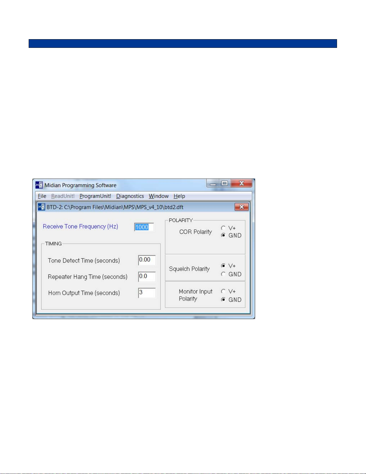
PRODUCT PROGRAMMING
Midian’s BTD-2 is programmed using the KL-4F programming interface and the MPS software. Please reference
the KL-4F manual for setup instructions of the software and hardware. From the product selection screen on the
MPS software, select the appropriate product name from the list and click OK.
Set the parameters of the product to fit the application. If any clarifications on a feature are required, move the
mouse cursor over the feature name until the question mark appears and right click, a definition of the feature will
be shown.
After entering the parameters, save the file by going to File - Save As. Enter the file name in the File Name block
and click Save. Saving the file will allow for quick and easy reprogramming of units.
Plug the unit into the P5 connector on the KL-4F using the double-ended wiring harness included in the KL-4.
Press and hold the PTT button on the KL-4F, then press and hold the Power button and then click “Program Unit”
in the menu bar to send the file to the unit. When programming is completed the buttons can be released.
Note: The BTD-2 is a non-readable unit.
Receive Tone Frequency (Hz): In this register program the desired burst tone frequency in Hz from 300 to 3000.
Tone Detect Time: This time is programmable for 0.00 to 0.99 seconds. This is the length of time that the burst
tone must be present prior to the BTD-2 decoding the tone. Midian recommends setting this to at least 0.30 to
avoid falsing.
Repeater Hang Time: This time is programmable for 0.0 to 9.9 seconds. If set to 0.0 the Hang Time is disabled.
This sets the amount of time that the BTD-2 must see a loss of COR prior to resetting the Monitor/Squelch Output
and the PTT Hang Time Output. The purpose is to keep the repeater active, so that it does not go inactive during
a conversation.
Horn Output Time: This time is programmable for 0-9 seconds. This sets the amount of time the Horn Output will
go low.
3
Page 4

COR Polarity: This sets the polarity the BTD-2 looks for to see COR as active, GND (Ground) or V+ (+5 V). The
BTD-2 looks for an active COR to validate a tone, so as not to false. The unit also resets the latched outputs by
seeing COR go inactive.
Squelch Polarity: This sets the polarity of the output of the Monitor/Squelch Output, GND (Ground) or V+ (+5 V).
Monitor Input Polarity: This sets the polarity the BTD-2 looks for to open the squelch of the radio to look for
activity, GND (Ground) or V+ (+5 V). When this input goes active the BTD-2 activates the Monitor/Squelch
Output.
4
Page 5

HARDWARE INSTALLATION
Be certain to follow standard anti-static procedures when handling any of Midian’s products.
P1-4 – Black – Ground – Connect to the nearest ground point.
P1-2 – Red - +5.5 – 15 VDC – Connect to switched B+ in the radio.
P1-3 – Brown – COR/COS – Connect to point in the squelch or CTCSS circuit that changes logic level when
carrier is received.
P1-6 – Orange – RX Tone Input – Connect to an audio point in the receiver, usually the high side of the volume
control or discriminator output. When using CTCSS, pick up the audio after the high pass filter.
P1-7 – Yellow – Monitor/Squelch Out – Connect to a point in the squelch circuit that normally changes logic level
with carrier. The squelch polarity is set in the programming software and by selecting the polarity of D-4 by
inserting either JU5 or JU6. R-47 can be changed to provide more or less current as needed. Do not allow the
Monitor/Squelch Output to conflict with the COR/COS lead input.
P1-10 – Gray/White – Horn Output - This provides a 0-9 second ground during ringing through Q7. JU7 (pads A
and B) must be installed and JU8 (pads A and C) must be uninstalled.
P1-8 – Green/White – PTT Hang Time Out – Connect to the radio’s PTT Input. This will keep the repeater keyed
after a loss of COR for the time set in the Hang Time.
P1-5 – Blue – Alert Tone/Speaker Audio – Connect to high side of the speaker. This provides a decode
indication tone. When using 20-40 Ohm speakers, the onboard resistor in series with Q3 should be sufficient.
When attaching this lead to a 4-8 Ohm speaker, add a 100-Ohm resistor in series with the lead to limit current.
P1-12 – Orange/White – Monitor/Program In – This input is connected for programming when the unit is plugged
into the KL-4F programming interface.
HARDWARE ALIGNMENT
RX Audio Input: On the BTD-2 adjust R65 so that Pin 14 of U2 (TP1) doesn’t quite clip when a 1 KHz tone
modulated at 3.3 KHz deviation from a signal generator is applied. If more level is needed remove R63 by cutting
JU1. Additionally, with an oscilloscope a symmetrical and clean square wave should be seen at Pin 8 of U2 (TP4).
COR/COS: If the radio only makes a minute change, it may be necessary to adjust the following values to cause
Q1 to change states:
R-5, R-6, & R-69
5
Page 6

OPERATION
The BTD-2 is designed to work in 2 configurations:
1. Remote Control/Alert: Upon decoding of the burst tone, the BTD-2 will activate the Horn and
Monitor/Squelch Outputs. The horn output will go momentarily low for the 0-9 seconds programmed. The
Monitor Squelch output will remain latched until reset.
2. Repeater Controller: Upon decoding of the burst tone, the BTD-2 will activate the Monitor/Squelch Output
and PTT Hang Time Output. Either of these outputs can be used to key the repeater and will keep it keyed for
the amount of time programmed (Repeater Hang Time) after COR/COS input has been lost. If the repeater
hang time is programmed to 0.0 the remote control/alert features listed in the above paragraph are activated.
Programming to 0.1 or higher activates the repeater controller feature.
Decode: Upon decode the unit will give the following outputs depending on the hardware configuration:
1. Momentary Horn Output: This will give an open collector output to ground for 0-9 seconds depending on the
programmed horn time.
2. Latched Monitor/Squelch Output: This output can either go from low to high or from high to low. With JU-5
installed and the squelch polarity programmed for V+ the output will go from high to low. With JU-6 installed
and the squelch polarity programmed for Ground the output will go from low to high.
Resetting of Outputs: Depending on programming the momentary output will reset automatically after 0-9
seconds. The Monitor/Squelch output is reset by cycling power or by the COR going inactive.
COR Input: The COR polarity, GND (Ground) or V+ (+5 V) must be programmed for the active carrier polarity of
the radio. If used the decoder must see an active COR before decoding. If this feature is not used, do not connect
this wire and program the polarity for GND.
6
Page 7

BTD-2 MOD-1272 ADDENDUM
Overview: MOD-1272 adapts a BTD-2 to mute ANI signaling packets, in particular Motorola’s MDC-1200
packets. It may also work with other signaling protocols that have a known single-tone preamble. In the case of
MDC, there is a preamble of 1800 Hz for approximately 27 msec. MOD-1272 changes the BTD-2 so that it is less
susceptible to falsing on voice as well as eliminating the need to connect the COR input. Another difference is that
the actual decode timing is 1/2 of that programmed. Also, the hardware has been modified to use a crystal for
greater decode accuracy. In all other respects, the product is identical to a BTD-2.
Operation: Upon detection of a signaling packet, the unit turns on transistor Q5 (PTT hang time out) for
approximately 200 msec. This output can be routed to the squelch circuit of a radio, or be used to clamp the audio
to ground* in order to mute the packet. This is the default configuration. The polarity of the squelch output can be
also be programmed so that the transistor is off during the mute period (set squelch polarity to V+) if the
application requires it.
Only 4 wires of the unit need to be connected: power, ground, RX tone in, and PTT hang time out. The RX level
control pot (R65) should be adjusted as described above. The decode sensitivity will not be as described
however. Expect packet detection to decrease below -14dB SINAD. Note: If you decide to clip the unneeded
wires, be sure not to clip the PROG ENABLE and PROG IN wires.
* Q5 can sink a maximum of 100 mA. Do not exceed or damage will result.
Programming Parameters:
The BTD-2 MOD-1272 comes preprogrammed with the above parameters. If different parameters are needed, the
KL-4F programming interface will be needed. Be certain to use the BTD-2 MOD-1272 programming file. Note that
the actual decode time is 1/2 of that programmed, so that the 0.03 tone detect time above causes the unit to
require a minimum of 15 msec of preamble tone in order to detect a signaling packet.
To increase the sensitivity of the unit, the tone detect time can be set to 0.02, but the risk of falsing on voice is
increased. Conversely, the tone detect time can be set to 0.04 to reduce the chance of falsing, but fewer packets
will be muted.
7
Page 8

TECHNICAL NOTES
tinuous Decode: The BTD-2 does not support continuous tone decode. For this feature the BTD-1 should be
Con
ordered instead.
MIDIAN CONTACT INFORMATION
MIDIAN ELECTRONICS, INC.
2030 N. Forbes Blvd. #101
Tucson, Arizona 85745 USA
Toll-Free: 1-800-MIDIANS
Main: 520-884-7981
E-mail: sales@midians.com
Web: www.midians.com
8
Page 9

1
1
2
2
3
3
4
4
5
5
6
6
D D
C C
B B
A A
CP
CJS
1997-02-14 DML
2013-05-14
C-4
1 of 1
7283
MIDIAN ELECTRONICS, INC.
DATE:
DESIGN:
DWN BY:
REV:
APPR
COPYRIGHT ©
REV
SHEET
PROJECT NUMBER
DOCUMENT NAME
SCHEMATIC
2013
BTD-2
.022u
C16
10K
R61
*
C22
100K
R62
-
+
2
3
1
LMV324
U2:1
-
+
6
5
7
LMV324
U2:2
-
+
9
10
8
LMV324
U2:3
-
+
13
12
14
LMV324
U2:4
4
VCCVCC
11
GNDGND
LMV324
U2:5
22K
R63
220K
R64
VAN
VAN
11
33
22
1M
R65
10K
R67
2.2K
R66
200K
R68
.01u
C17
560p
C27
15K
R1
100K
R2
.022u
C1
100p
C2
390K
R3
*
C29
1.2M
R4
VAN
+5V
OSC2
36
TCMP
33
VDD
38
VPP
43
SS
32
B3
11
D7
34
OSC1
37
B0
8
B1
9
A5
2
A6
1
A7
44
A4
3
A3
4
A2
5
A1
6
A0
7
C4
21
C5
20
C3
23
C0
26
C1
25
C2
24
C6
19
C7
18
B4
12
B7
15
B6
14
GND
17
RES
41
B2
10
TCAP
35
IRQ
42
B5
13
SCK
31
MOSI
30
MISO
29
RDI
27
TDO
28
NC1
16
NC2
22
NC339NC4
40
68705FP
U1
.1u
C15
+5V
20K
R8
B25
Q1
*
R69
100K
R5
10K
R6
+5V
10K
R9
2 1
A6
D1:1
31
A6
D1:2
560p
C6
+5V
1
P2:1
2
P2:2
3
P2:3
4
P2:4
5
P2:5
6
P2:6
7
P2:7
8
P2:8
0R
JU2
10K
R13
21
A6
D2:1
3 1
A6
D2:2
560p
C7
+5V
100K
R10
100K
R11
100K
R12
+5V
10K
R14
2 1
A6
D3:1
31
A6
D3:2
560p
C8
+5V
CS
1
SCLK
2
SI
3
SO
4
VCC
8
NC1
7
NC2
6
GND
5
9346
U3
100K
R16
.1u
C14
560p
C4
.1u
C9
7.5K
R56
10K
R55
.47u
C13
10K
R15
.47u
C12
.001u
C11
560p
C10
5206
IN1
1
ENA
3
GND
2
RES
4
OUT
5
VR1
+5V
+5V
VAN
VIN
4.7K
R54
4.7K
R53
4.7K
R52
4.7K
R48
4.7K
R46
100p
C25
1K
R49
1K
R50
1K
R51
BSS
Q5
BSS
Q6
BSS
Q7
BSS
Q8
*
JU7
560p
C26
560p
C28
B25
Q4
47K
R47
21
A7
D4:1
31
A7
D4:2
VIN
*
JU6
JU5
JU8
IN+
1
IN-
2
GS
3
VREF
4
IC*
5
IC*
6
NC
7
OSC1
8
OSC2
9
VSS
10
TOE
11
Q1
12
Q2
13
Q3
14
Q4
15
NC
16
ST
17
EST
18
ST/GT
19
VDD
20
*
U4
11
33
22
*
R41
470K
R42
1.2M
R43
SD1
D5
.1u
C3
+5V
+5V
20K
R24
20K
R26
20K
R28
20K
R30
20K
R32
20K
R34
20K
R36
20K
R38
20K
R39
10K
R25
10K
R27
10K
R29
10K
R31
10K
R33
10K
R35
10K
R37
D25
Q3
4.7K
R44
33R
R7
VIN
22K
R18
22K
R19
100K
R20
560p
C19
.01u
C18
11
33
22
10K
R22
39K
R21
27K
R23
.47u
C20
100p
C21
D25
Q2
VIN
VIN
.022u
C5
100K
R40
3.58 MHz.
Y1
22p
C23
22p
C24
4.7M
R17
TX/TONE OUT[GRN]TX/TONE OUT[GRN]
P1:1
5.5V - 15V VIN[RED]5.5V - 15V VIN[RED]
P1:2
COR/COS IN[BRN]COR/COS IN[BRN]
P1:3
GND[BLK]GND[BLK]
P1:4
ALERT TONE/SPEAKER OUT[BLU]ALERT TONE/SPEAKER OUT[BLU]
P1:5
RX/TONE IN[ORG]RX/TONE IN[ORG]
P1:6
MON/SQ OUT[YEL]MON/SQ OUT[YEL]
P1:7
MIC MUTE OUT[GRN/W]MIC MUTE OUT[GRN/W]
P1:8
PTT OUT[WHT]PTT OUT[WHT]
P1:9
SCAN/DISABLE OUT/HORN OUT[GRY/W]SCAN/DISABLE OUT/HORN OUT[GRY/W]
P1:10
PTT IN[GRY]PTT IN[GRY]
P1:11
MONITOR/PROG IN[ORG/W]MONITOR/PROG IN[ORG/W]
P1:12
EMER/AUX[VIO]EMER/AUX[VIO]
P1:13
*
UK1
+5V
TP5
PTT LED
TP4
CALL LED
TP3
BUSY LED
D
F
E
G
TP2
TP1
TP6
NOTES:
JU1
JU3
A
B
C
TO USE JU1, REMOVE R63
TO USE JU3, REMOVE R21
COC22
PIC2201 PIC2202
COR62
PIR6201PIR6202
COTP1
COC16
PIC1601 PIC1602
PIP106
COP1:6
PIP104
COP1:4
PIP103
COP1:3
PIP1011
COP1:11
PIP1013
COP1:13
PIP1012
COP1:12
PIP102
COP1:2
PIR201
COR61
PIR6302
COR63
PIR6301
COR2
PIR202
PIC1001
PIC1002
PIR6101PIR6102
PIR6402
COR64
PIR6401
COC1
PIC201
COC2
PIC202
PIC1101
COC10
PIC1102
PIU2012
PIU2013
PIC101PIC102
PIU205
PIU206
PIC602
PIC601
PIC702
PIC701
PIC802
PIC801
COC11
COU2:4
PIR6503
COR65
COU2:2
COC6
COC7
COC8
PIC1202
PIC1201
PITP101
PIU2014
PIR6502
PIR6501
PIU207
COUK1
PID101 PID103
PID101
COD1:1
PID102
COD2:1
PID201 PID202
COD2:2
PID201
PID203
PID301 PID303
PID301
COD3:1
PID302
PIVR101
PIVR103
COC12
COVR1
PIR6701 PIR6702
PIR6602
COR66
PIR6601
COR1
PIR301 PIR302
PIUK101PIUK102
COD1:2
COD3:2
COR67
PIR101PIR102
COR3
COC29
PIR901
COR9
PIR902
PIR1302
COR13
PIR1301
PIR1402
COR14
PIR1401
PIR1501
COR15
PIR1502
PIVR104
PIVR102
PIC1701
COC17
PIC1702
PIC2902
PIC2901
COR6
PIVR105
COR68
PIR6801PIR6802
COR4
PIU2010
PIU209
COU2:3
COR69
PIR601PIR602
PIR502
COR5
PIR501
COR55
PIR5501 PIR5502
PIC1302
COC13
PIC1301
PIC2701
COC27
PIC2702
COTP2
PITP201
PIR401PIR402
PIU208
PIR6902
PIR6901
PIQ10B
PIR5602
COR56
PIR5601
COU2:1
PIU203
PIU202
PIR801
COR8
PIR802
PIQ10C
PIQ10E
PIC901
PIC902
COQ1
COC9
PIU201
COC14
PIC402
COC4
PIC401
COP2:1
COP2:2
COP2:3
COP2:4
COP2:5
COP2:6
COP2:7
COP2:8
PIC1402
PIC1401
PIU204
PIU2011
COR10
PIP201
PIP202
PIP203
PIP204
PIP205
PIP206
PIP207
PIJU202
PIP208
COJU2
PIU308
PIU307
PIU306
COU3
COU2:5
PIR1001
PIR1101
COR11
COR12
PIR1002
PIR1102
PIJU201
PIR1202
PIR1201
PIU301
PIU302
PIU303
PIU304PIU305
COR16
PIR1602
PIR1601
PIU1043
PIU1035
PIU1042
PIU1028
PIU1018
PIU1019
PIU1020
PIU1021
PIU1023
PIU1024
PIU1025
PIU1022
PIU1026
PIU1027
PIU1015
PIU1031
PIU1030
PIU1029
PIU1041
PIU1017
PIC1501
PIC1502
PIU1032
COU1
PIU1016
PIU1039 PIU1040
COC15
PIU1037PIU1038
COR17
COY1
PIC2302
COC23
PIC2301
PIU1036
PIU1034
PIU1013
PIU1044
PIU101
PIU102
PIU103
PIU104
PIU105
PIU106
PIU107
PIU1014
PIU1011
PIU1012
PIU1010
PIU109
PIU108
PIU1033
PIR1701PIR1702
PIY101PIY102
COC24
COR46
PIR4601 PIR4602
COR48
PIR4801PIR4802
COR49
PIR4901 PIR4902
COR50
PIR5001PIR5002
COR51
PIR5101PIR5102
COR52
PIR5201 PIR5202
COR53
PIR5301 PIR5302
COR54
PIR5401PIR5402
PIC2402
PIC2401
COTP3
PITP301
COTP4
PITP401
COTP5
PITP501
COD
PID01
COE
PIE01
COF
PIF01
PIQ70G
PIQ80G
PIR2401 PIR2402
COR24
COR26
PIR2601 PIR2602
COR28
PIR2801 PIR2802
COR30
PIR3001 PIR3002
COR32
PIR3201 PIR3202
COR34
PIR3401 PIR3402
COR36
PIR3601 PIR3602
COG
COR38
PIG01
PIR3801 PIR3802
PIJU701 PIJU702
PIQ70D
COQ7
PIQ70S
PIQ80D
COQ8
PIQ80S
COtb0sch1
PIR2502
COR25
PIR2501
PIR2702
COR27
PIR2701
PIR2902
COR29
COR18
PIR1801 PIR1802
COR19
PIR1902
PIC1802
COC18
PIC1801
PIR2901
PIJU601 PIJU602
PIJU501
PIQ60D
COQ6
PIQ60S
PIR2102
COR21
PIR2101
PIR4402
COR44
COJU6
PIJU502
COJU5
PIC2601
COC26
PIC2602
PIR3102
COR31
PIR3101
PIR3302
COR33
PIR3301
PIR3502
COR35
PIR3501
PIR3702
COR37
COR39
PIR3701
PIR3901 PIR3902
COTP6
PITP601
COQ4
PIC2801
PIC2802
PIC2501
PIC2502
COD4:2
PID401 PID403
PID401 PID402
COC28
PIQ60G
COC25
COD4:1
PIQ40B
PIQ50G
COJU7
COJU8
PIJU801
PIR4701
COR47
PIR4702
PIQ40C
PIQ40E
PIQ50D
COQ5
PIQ50S
PIJU802
PIR2001
PIR2002
PIR1901
PIC1902
PIC1901
PIQ30B
PIR4401
COR20
PIQ20B
COC19
COR22
PIQ30C
COQ3
PIQ30E
PIQ20C
COQ2
PIQ20E
PIR2203
PIR2202
PIR2301 PIR2302
PIR2201
PIU408
PIU4017
PIU4011
PIU4012
PIU4013
PIU4014
PIU4015
PIU401
PIU404
PIU409
COR7
PIR701 PIR702
COR23
PIU4020
COU4
COC20
PIC2001PIC2002
PIC2102
PIC2101
PIU403
PIU402
PIU4019
PIU4018
PIU4016
PIU407
PIU405
PIU406
PIU4010
PIP101
COP1:1
COC21
PIR4103
COR41
PIR4102
PIR4101
PIR4202
COR42
COR43
PIR4201
PIR4301 PIR4302
PIP105
COP1:5
PIP107
COP1:7
PIP108
COP1:8
PIP109
COP1:9
PIP1010
COP1:10
PIC502
COC5
PIC501
PIR4002
COR40
PIC302
PIR4001
PIC301
PID502
COD5
PID501
COC3
Page 10

- This page intentionally left blank -
Page 11

COtb0sch1
COP1
PAP1013
PAP1012
PAP1011
PAP1010
PAP109
PAP108
PAP107
PAP106
PAP105
PAP104
PAP103
PAD201
COD2
PAD202 PAD203
PAD103
COD1
PAD101
PAD102
COC26
PAC2602PAC2601
COC28
PAC2801 PAC2802
PAR5502
PAR5602
COR56
PAR5501
PAR5601
PAJU501
COJU5
PAJU502
PAJU602
COJU6
PAJU601
COR55
PAD301
COD3
PAD302 PAD303
PAQ40C
PAD402
PAD403
PAR702
PAR701
PAVR105
PAC1201
PAC1202
COVR1
COC12
PAVR101
PAVR104
PAQ30E
COQ3
PAVR103PAVR102
PAC802
PAC2402
COC8
PAC801
PAC2401
COC23
COQ4
PAQ40E
PAR4602
PAQ40B
COD4
PAD401
COR7
PAR4402
PAR4401
COR46
PAR4601
COTP6
PAR4702
COR47
PAR4701
COR44
COR20
PAR2001 PAR2002
PAQ30B
PAVO10C
PAQ20C
PAR1701
COR17
COC24
PAR1702
PAC2302PAC2301
PAR4801
COR48
PAR4802
PATP601
PAC1901
COC19
PAC1902
COQ2
PAVO10E
PAQ20E
PAVO10B
PAQ20B
COC18
COR19
PAR1901 PAR1902
PAY101PAY102
PAQ30C
PAP102
COVO1
PAP101
PAC1001
PAC1002
PAC1101
COC10
COC11
PAC2101
PAC1102
PAC2102
COR23
PAR2302 PAR2301
COC21
COC20
COR22
PAR2202
PAC2001 PAC2002
PAR2102
PAR2203
COR21
PAR2101
PAR2201
PAR5401
COR54
PAR5402
PAVO1034
PAU1034
PAVO1035
COY1
PAU1035
PAVO1036
PAU1036
PAVO1037
PAU1037
PAVO1038
PAU1038
PAVO1039
PAU1039
PAVO1040
PAU1040
PAVO1041
PAU1041
PAVO1042
PAU1042
PAVO1043
PAU1043
PAVO1044
PAU1044
PAC1802PAC1801
PAR2401
COR24
PAR2402
PAR1802
COR18
COR25
PAR2502 PAR2501
PAR1801
COR27
PAVO1033 PAVO1032 PAVO1031 PAVO1030 PAVO1029
PAU1033
PAU1032 PAU1031 PAU1030
COU1
PAU102
PAU101
PAU103
PAR2601
PAR2801
PAR3001
COR26
PAR2602
PAR2701PAR2702
COR30
COR28
PAR2802
PAR3002
COR29
PAR2902 PAR2901
COR31
PAR3101PAR3102
PAVO1028
PAVO1027 PAVO1026 PAVO1025 PAVO1024 PAVO1023
PAU1029 PAU1028 PAU1027
PAU104
PAR3201
COR32
PAR3202
COR33
PAR3302 PAR3301
COR35
PAU1026 PAU1025
PAU1024 PAU1023
PAVO109
PAVO1011PAVO1010
PAU109PAU108
PAU107PAU106PAU105
PAR3401
PAR3601
COR34
COR36
PAR3402
PAR3602
COR37
PAR3702 PAR3701
COR39
PAR3501PAR3502
PAU1011PAU1010
PAR3801
PAVO10D
PAQ70D
COR38
PAR3802
PAQ80D
PAR3901PAR3902
PAVO1022
PAU1022
PAVO1021
PAU1021
PAVO1020
PAU1020
PAVO1019
PAU1019
PAVO1018
PAU1018
PAVO1017
PAU1017
PAVO1016
PAU1016
PAVO1015
PAU1015
PAVO1014
PAU1014
PAVO1013
PAU1013
PAVO1012
PAU1012
COQ7
PAVO10S
PAQ70S
PAVO10G
PAQ70G
COQ8
PAQ80S
PAQ80G
PAJU201
COJU2
PAJU202
PAR5301
COR53
PAR5302
COP2
PAVO108
PAP208
PAVO107
PAP207
PAVO106
PAP206
PAVO105
PAP205
PAVO104
PAP204
PAVO103
PAP203
PAVO102
PAP202
PAVO101
PAP201
Page 12

COtb0sch2
COP2
PAP208
PAVO208
PAP207
PAVO207
COTP5
PATP501
PAR1002PAR1001
COR11
PAC1401PAC1402
COTP4
PAP206
PAVO206
COTP3
PATP301
PAP205
PAVO205
PAP204
PAVO204
PAP203
PAVO203
PAP202
PAVO202
PAVO201
PAP201
PAR4902
COR49
PAR4901
COD5
COJU7
PAR5101
COR51
PATP401
PAR5102
PAR5001
COR50
PAR5002
COR43
PAD501
PAD502
COC3
PAJU701
PAJU702
PAJU802
PAR4301 PAR4302
COR42
PAR4202PAR4201
PAC301 PAC302
PAJU801
COJU8
COR10
PAR1101 PAR1102
COR12
PAR1202 PAR1201
COC14
COU3
PAU305
PAU306
PAU307
PAU308
PAR1302
PAR1402
COR13
COR14
PAR1301
PAR1401
PAG01
COG
PAF01
COF
PAU4011PAU4010
PAVO2012
PAU4012
PAVO2013
PAU4013
PAVO2014
PAU4014
PAVO2015
PAU4015
PAVO2016
PAU4016
PAVO2017
PAU4017
PAVO2018
PAU4018
PAVO2019
PAU4019
PAVO2020
PAU4020
COU4
PAUK101
PAR901
COR9
COUK1
PAR902
PAUK102
COR16
PAR1602PAR1601
PAU304
PAU303
PAU302
PAU301
PAE01
COE
PAD01
COD
COC15
PAC1502PAC1501
PAR801
PAR1501
COR8
COR15
PAR802
PAR1502
COR52
PAR5202 PAR5201
PAVO2010 PAVO2011
PAVO209
PAU409
PAU408
PAU407
PAU406
PAU405
PAU404
PAU403
PAU402
PAU401
PAVO20B
PAQ10B
COVO2
PAR4102
COR68
PAR6802PAR6801
COR67
PAR6702
COC17
PAC1701PAC1702
COR1
PAR101 PAR102
COR2
PAR202 PAR201
COC1
PAC102
PAC101
PAVO20C
PAQ10C
COQ1
PAVO20E
PAQ10E
COR41
PAU201
PAU202
PAU203
PAU204
PAU205
PAU206
PAU207PAU208
PAC2502
COC25
PAC2501
PAR4103
PAR4101
COC27
PAC2701PAC2702
PAR6701
COR65
PAR6502
COU2
COR3
PAR302 PAR301
COC2
PAC201
PAC202
PAQ60D
COQ6
PAQ60G
PAQ60S
COR4
PAR402
COC29
PAC2901PAC2902
COQ5
PAQ50G
PAR6503
PAR6501
PAU2014
PAU2013
PAU2012
PAU2011
PAU2010
PAU209
PAR401
PAVO20D
PAQ50D
PAVO20S PAVO20G
PAQ50S
PAR6601
COR66
PAR6602
PATP101
COTP1
PAR6302
PAR6402
COR64
COR63
PAR6301
PAR6401
COR62
PAR6201
COC22
PAC2202
PATP201
COC4
PAC402
COC9
COTP2
PAC901
PAC1302
COC13
PAR501
PAR502
PAC1301
COR5
COC7
PAC702 PAC701
COC6
PAC601PAC602
PAC1602
PAR6102
COR61
COC16
PAC1601
PAR6101
PAR6202
PAC502
COC5
PAC2201
PAC501
PAC401
PAC902
PAR6902
COR69
PAR6901
PAR4002
COR40
PAR4001
PAR602
COR6
PAR601
 Loading...