

Page 1
Innovative Time and Attendance Solutions
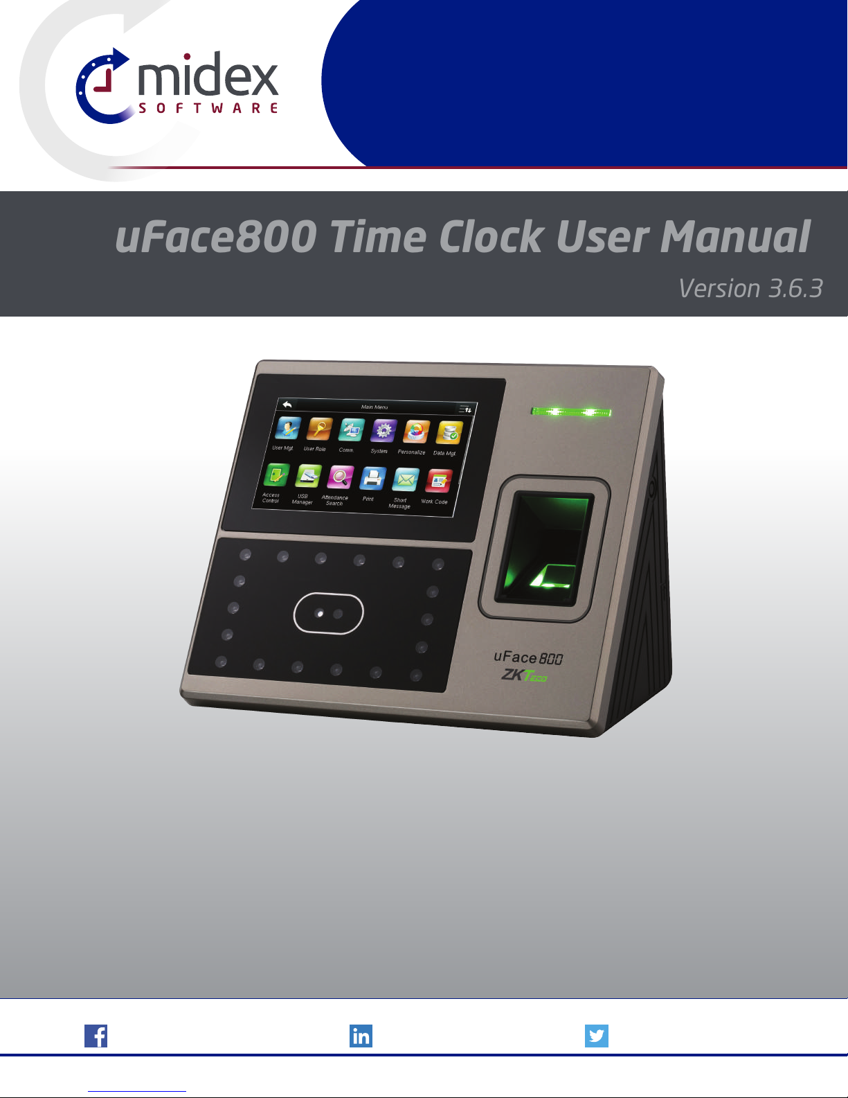
uFace800 Time Clock User Manual
Version 3.6.3
uFace800
Visit: MidexTimeAndAttendance.com | Call: 1-888-544-7878 | Email: [email protected]
/TimeAndAttendanceSoftware | /company/midex-software | @MidexSoftware
©2003-2018 Midex Enterprises Ltd. | All designs and specifications are subject to change without notice.
Page 2

CONTENT
USER MANAGEMENT 5
1
1.1 New User ...................................................................... 6
1.2 All Users ........................................................................ 13
1.3 Single Line ..................................................................... 14
USER ROLE 16
2
COMMUNICATION 18
3
3.1Ethernet ........................................................................19
3.2 Serial Communication .......................................................19
3.3 PC Connection ................................................................ 20
3.4 Wireless Network ............................................................. 21
3.5 Cloud Server Settings ........................................................ 22
3.6 Wiegand Setup ............................................................... 24
SYSTEM 26
4
4.1 Date Time .....................................................................27
4.2 Attendance .................................................................... 27
4.3 Face .............................................................................30
4.3 Fingerprint ....................................................................31
4.4 Reset ...........................................................................33
4.5 USB Upgrade .................................................................. 33
PERSONALIZE 34
5
5.1 User Interface ................................................................. 35
5.2 Voice ............................................................................38
5.3 Bell Schedules ................................................................. 39
5.4 Punch State Options.........................................................43
5.5 Shortcut Key Mapping ....................................................... 44
5.6 Manual Add Log .............................................................49
Page 3
CONTENT
DATA MANAGEMENT 51
6
6.1 Delete Data .................................................................... 52
6.2 Backup Data ................................................................... 53
6.3 Restore Data ...................................................................54
ACCESS CONTROL 56
7
7.1 Time Schedule ................................................................57
7.2 Access Group .................................................................57
USB MANAGER 61
8
8.1 Download .....................................................................62
8.2 Upload .........................................................................63
8.3 Download Options ...........................................................63
ATTENDANCE SEARCH 65
9
SHORT MESSAGE 68
10
10.1 New Message ................................................................ 69
10.2 Public Messages .............................................................71
10.3 Personal messages .......................................................... 71
10.4 Draft Messages .............................................................. 71
10.5 Message Options ........................................................... 72
WORK CODE 73
11
11.1 New Work Code .............................................................74
11.2 ALL WORK CODES ........................................................... 75
11.3 SET WORK CODE ............................................................75
Page 4

CONTENT
JOB CODE 77
12
12.1 New Job Code ...............................................................78
12.2 All Job Codes ................................................................79
12.2 All Job Codes ................................................................82
12.3 Job Code Options ........................................................... 85
12.4 Job Group Option Menu Operation ...................................... 87
TIP CODE 90
13
13.1 Tip code settings ............................................................ 91
13.2 Tip code ...................................................................... 92
AUTOTEST 96
14
14.1 All Test ........................................................................97
14.2 Test LCD ...................................................................... 97
14.3 Test Voice ..................................................................... 99
14.4 Test Keyboard................................................................ 99
14.5 Test Fingerprint Sensor ..................................................... 99
14.6 Test FACE .....................................................................99
14.7 xs Test Clock RTC .......................................................... 100
SYSTEM INFORMATION 101
15
15.1 Device Capacity ........................................................... 102
15.2 Device Info ................................................................. 102
15.3 Firmware Info .............................................................. 103
Page 5

1
USER MANAGEMENT
Page 6
1
USER MANAGEMENT
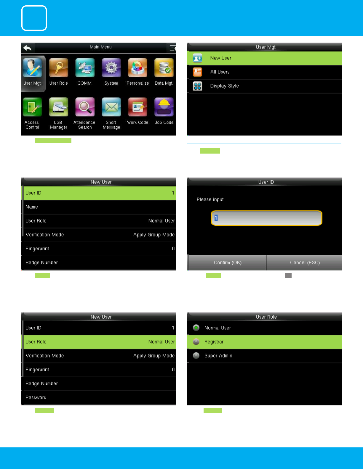
Select User Management .
1.1 NEW USER
Select New User .
Enter the User ID by using the keypad and press OK.Select User ID .
Click on Registrar .Select User Role .
6
Page 7
1
USER MANAGEMENT
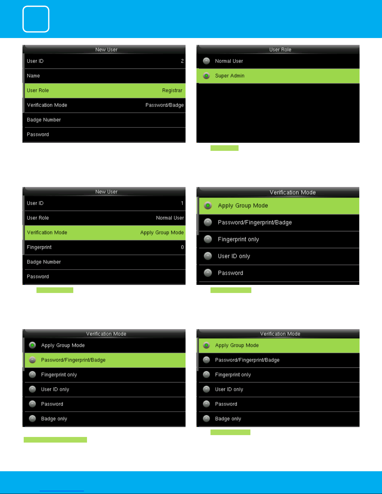
A user with “Registrar” is able to “Add”, “Delete” and “Edit” standard users to the
device.
He is also able to view “Standard Attendance Data” for existing users on the
clock.
Select Verication Mode
Verication mode is basically used to verify the user.
Select Super Admin .
The super administration has rights to all the menu functions.
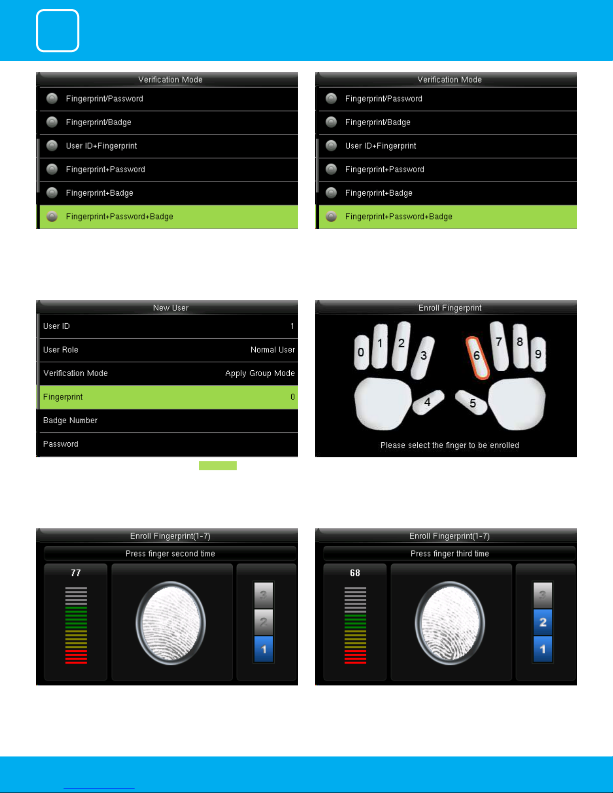
Select Apply Group Mode . By pressing the apply group mode the user can
verify himself with all the options that are available in verication mode.
By clicking the option above the user can verify himself either with his/her
Fingerprint/Password or Badge .
Select Apply Group Mode .
7
Page 8
1
USER MANAGEMENT
When you select the option from above the user need all three things to
verify himself or it won’t verify.
To enroll the ngerprint for the new user select ngerprint .
When you select the option above the user needs his/her ngerprint and
either badge or user id to verify himself.
When there is / sign it means you can either use one option from 2 to verify.
Place your nger on the ngerprint sensor properly.
Place the same nger on the ngerprint sensor for the second time. After that, you can again place the same nger on the ngerprint sensor.
8
Page 9
1
USER MANAGEMENT
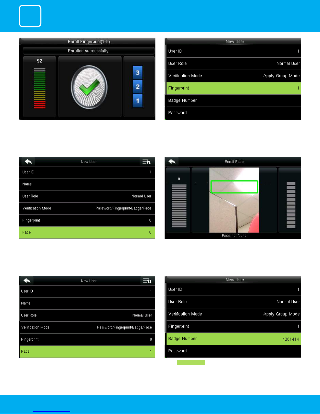
Enrollment succeeds. If the enrollment fails, the system will display a prompt
message and return to the [Enroll Fingerprint] interface. In this case, you
need to repeat the operations of step 2
Select “Face”.
After the ngerprint is enrolled successfully the ngerprint will be shown as
1 as above which means one ngerprint is enrolled.
After you select face place your place in the green box until the face gets
registered for that user.
After the face is recognized for that user it will show as 1 face has been
registered as above.
Select Badge Number .
9
Page 10
1
USER MANAGEMENT
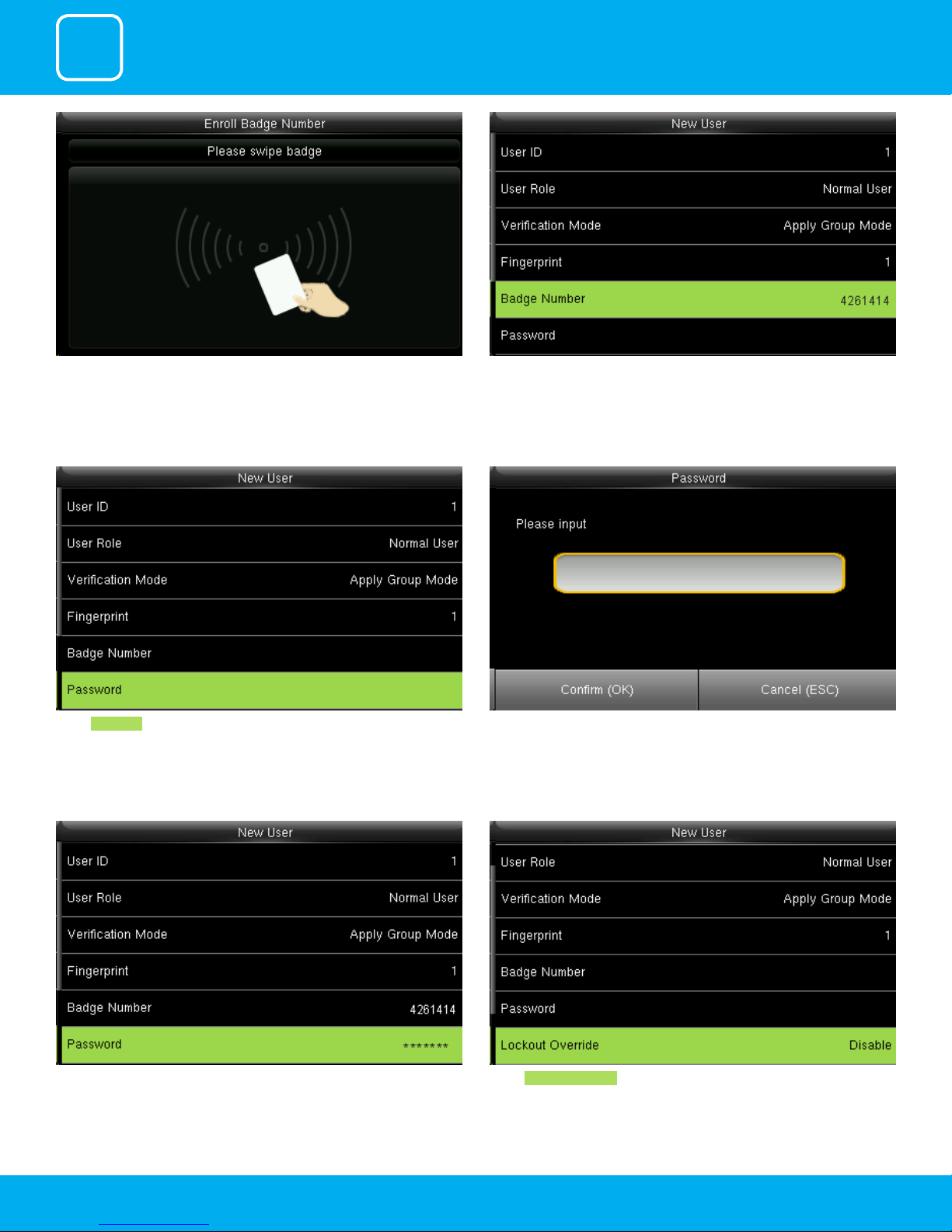
When you select the badge number it will tell you to swipe the badge/rd
card to enroll.
Select Password . Here you can input the password by using the keypad to enroll.
When you swipe the badge number the badge number will be displayed as
above.
Here I swiped badge number 4261414 and that number is enrolled for that
user.
Once you entered the password the above image will be displayed for that
user with his/her ngerprint the badge number and password that needs
him/her to enter.
Select Lockout Override .
10
Page 11
1
USER MANAGEMENT
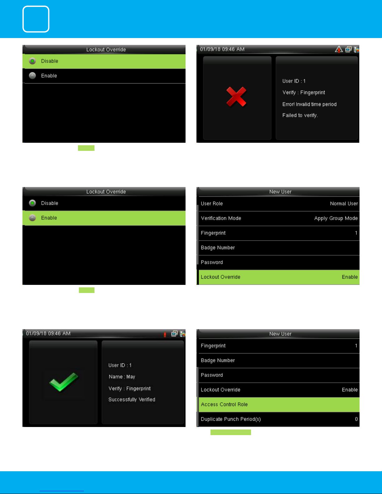
Select lockout override as Disable . A user punches in o the activate schedules, the device will notify the user
by “Error! Invalid time period Failed to verify.”
Select lockout override as Enable . When you enable this function the above image will be displayed.
A user punches in o the activate schedules, the device will notify the use by
“Successfully Veried.” as shown below
Select Access Control Role .
11
Page 12
1
USER MANAGEMENT
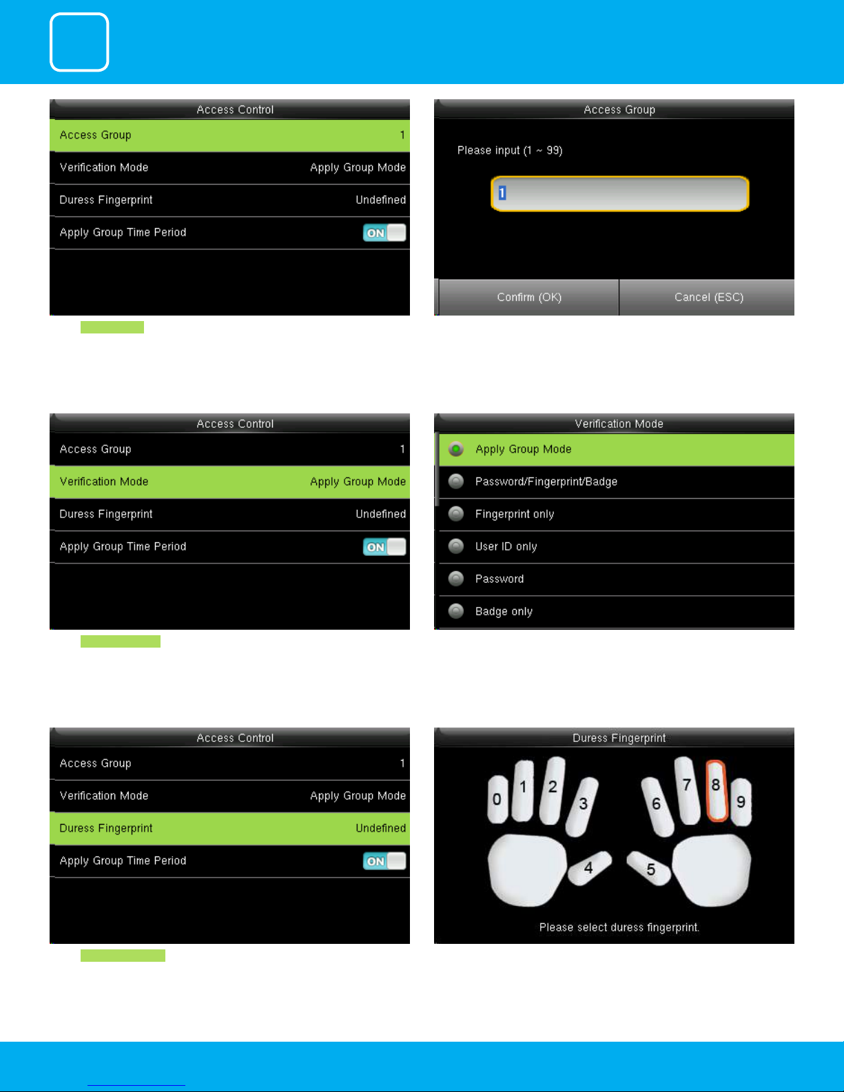
Select Access Group . You can change the number for that group in the input section above using
the keypad.
Select Verication mode.
Select Duress Fingerprint .
In verication mode, you can select apply group mode which will select all
the methods of verication as shown above.
Place your nger as shown above to select your duress ngerprint.
12
Page 13
1
USER MANAGEMENT
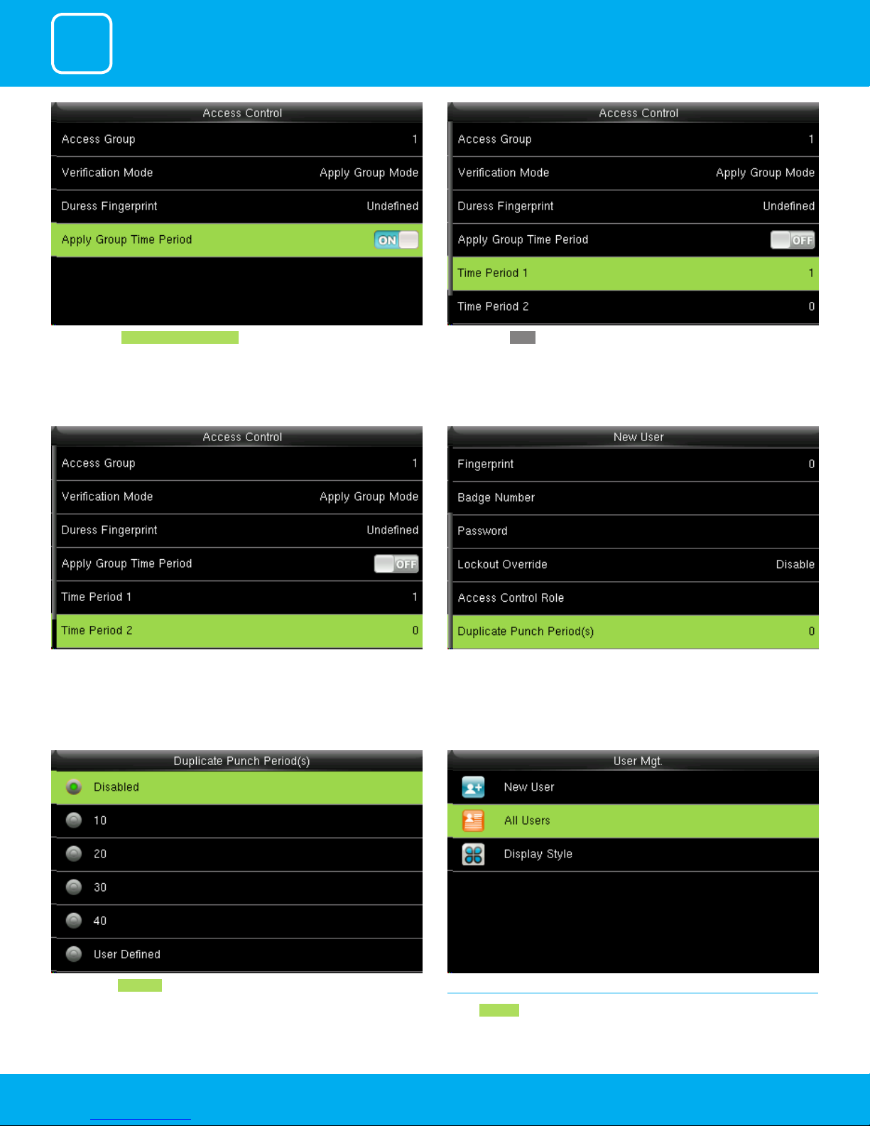
Press to select Apply Group Time Period, to select to whether the user use his/
her group’s default time zone.
Similarly, you can choose time period 2.. Select duplicate punch period.
When select OFF , Press to select Time period 1.
Here you can Disabled or select the punch period you want. 1.2 ALL USERS
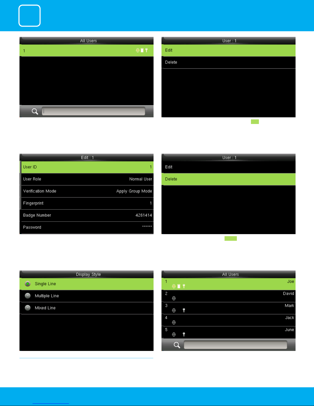
Select All users .
13
Page 14
1
USER MANAGEMENT
Click to select “All User”. Here you can edit the user informationby selecting Edit .
The User ID cannot be modied, and the other operations are similar to
those performed to add a user.
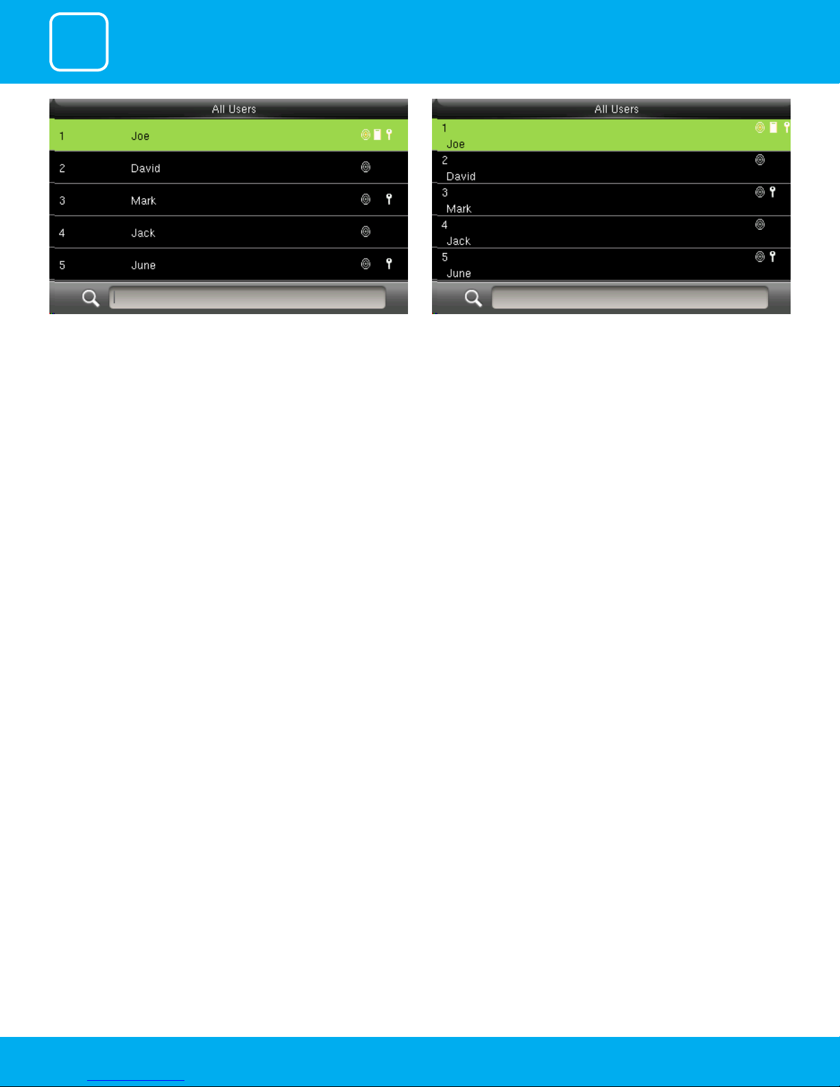
1.3 SINGLE LINE
Click to select display style you wish to apply.
If you want to delete the user select Delete as shown above and the user
will get deleted.
Single Line
14
Page 15
1
USER MANAGEMENT
Multiple line Mixed Line
15
Page 16

2
USER ROLE
Page 17
2
USER ROLE
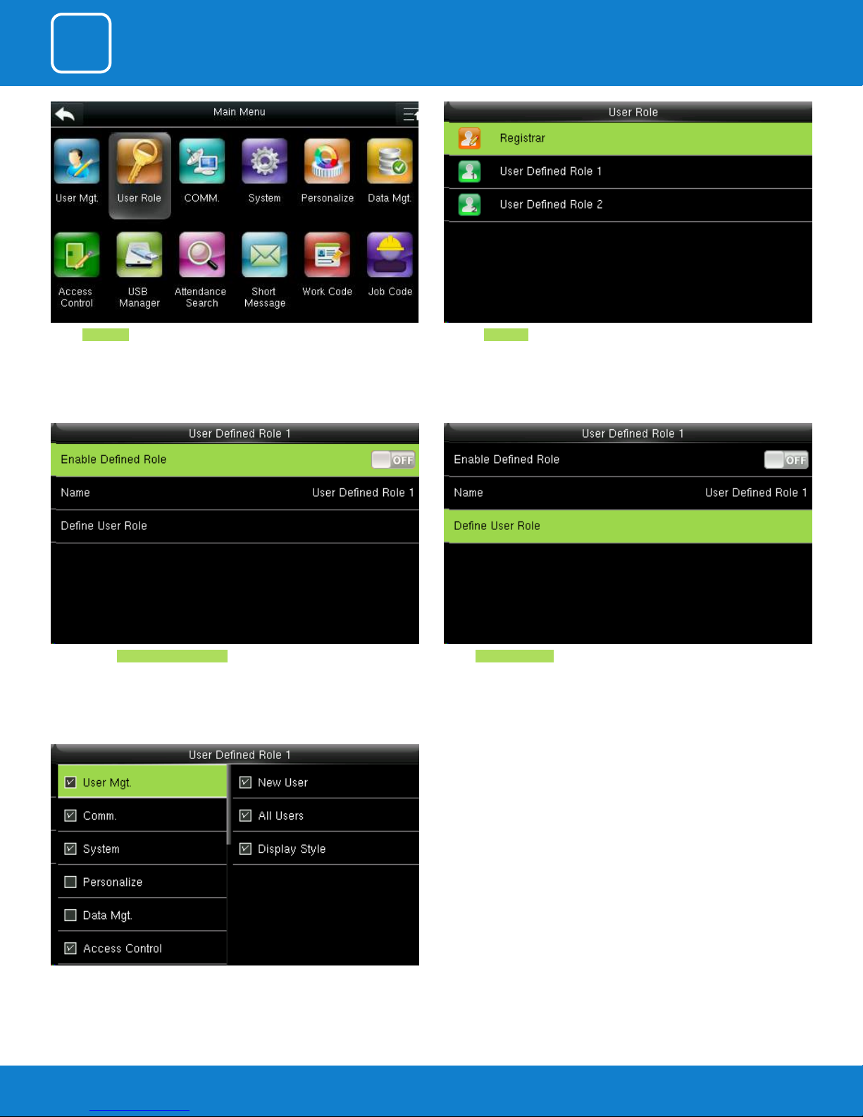
Select User Role .
Click on Registrar .
He is also able to view “Standard Attendance Data” for existing users on the
clock
Select Dene User Role .Here you can Enable the dened Role for user by turning it ON.
Here you can select the rights you want to assign.
17
Page 18

3
COMMUNICATION
Page 19
3
COMMUNICATION
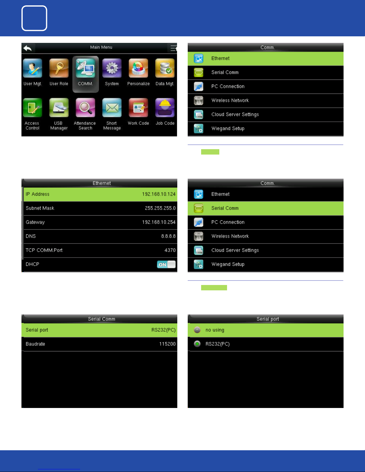
Celect “COMM” .
IP Address: IP is 192.168.1.201 by default. You can modify it if it is necessary.
But it cannot be the same with that of PC.
3.1ETHERNET
Select Ethernet.
3.2 SERIAL COMMUNICATION
Select Serial Comm .
RS232: Whether use RS232 to communicate. Select RS232 is to be used.Select “Serial Port”.
19
Page 20
3
COMMUNICATION
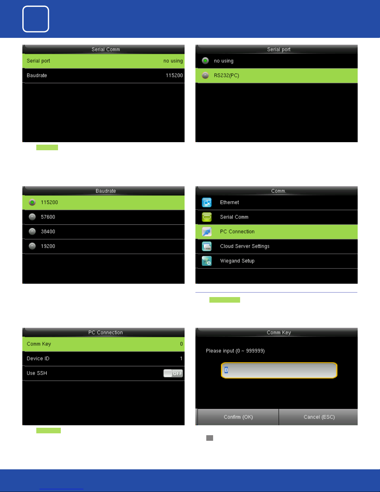
Baudrate: Used for communication with PC. Select Serial Port as no using if you do not want to use the port.
There are ve options: 9600, 19200, 38400, 57600 and 115200. If the communication speed is high, RS232 is recommended. If the communication speed
is low, RS 485 is recommended
Select Comm Key .
3.3 PC CONNECTION
Select PC connection .
Enter a password, using the keypad in the input box as shown above and
Click OK.
20
Page 21
3
COMMUNICATION
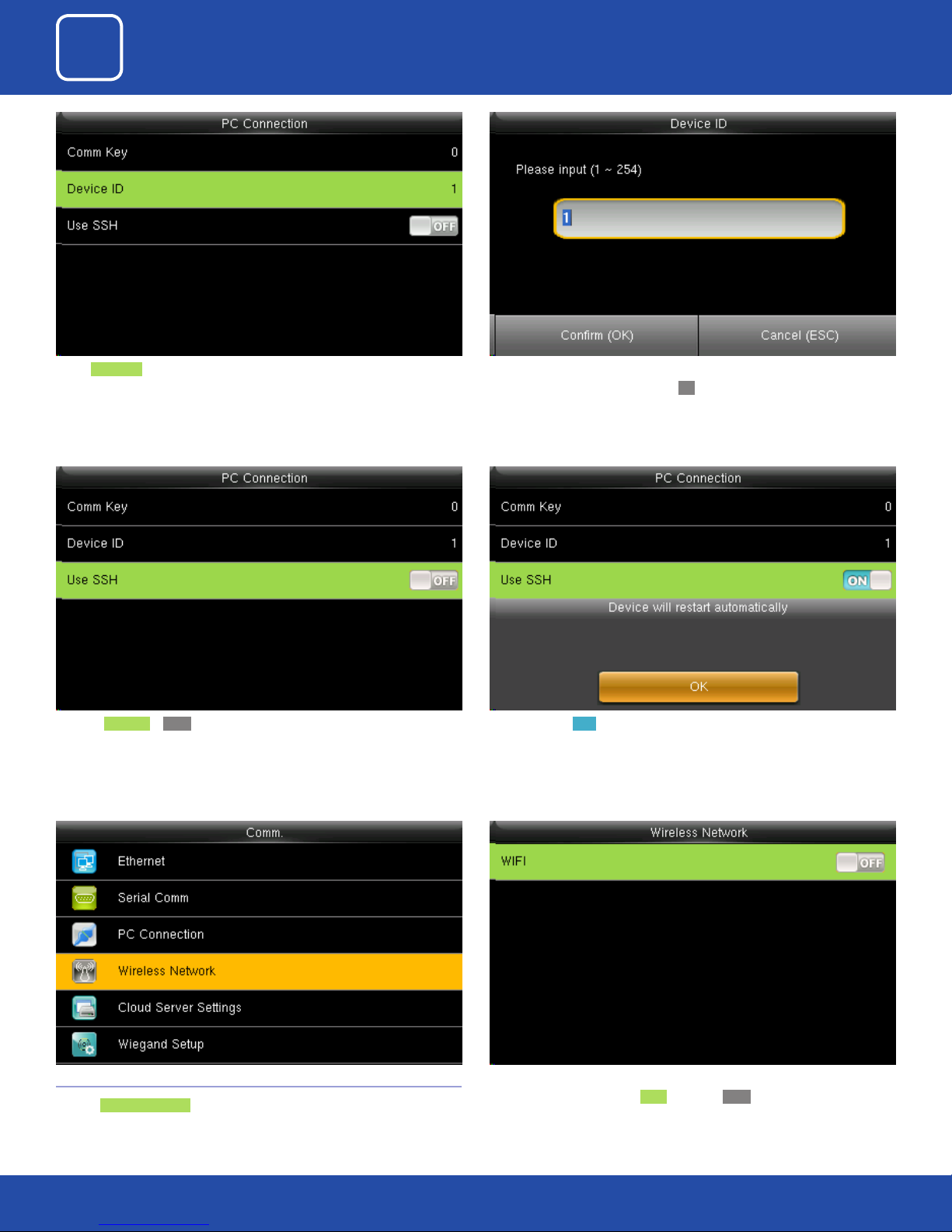
Select Device ID ..
Here the Use SSH is OFF When you turn ON the “SSH” function the device will restart automatically
Here you can put the number for this device by using the keypad in the
input screen as above and hit press OK.
as shown above.
When this function is enabled you cannot “Telnet” into the clock as it will
disable that function.
3.4 WIRELESS NETWORK
Click on Wireless Network .
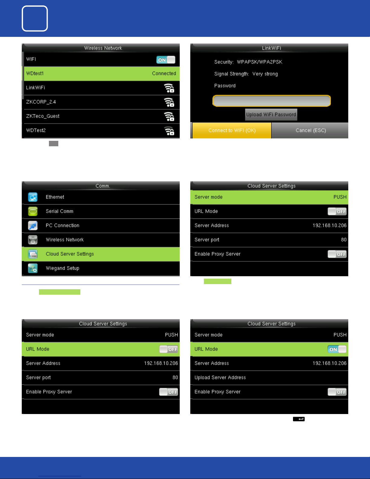
When you select the wireless network option the following window will
appear in which as a default WIFI would be OFF .
21
Page 22
3
M/
COMMUNICATION
You can turn ON the wireless network and the networks available in the
range would be displayed as above.
3.5 CLOUD SERVER SETTINGS
Click on Cloud Server Setting .
You can select any wireless network you wish to connect and you can upload the password via “USB” or by using the keypad on the clock.
Once you upload the password you can press “Connect to WFI(OK)” and the
following network will get connected.
Select Server mode as “PUSH” as shown above.
It refers to your push server address.
Here the “URL” MODE IS “OFF”. You can turn the “URL” mode “ON” by pressing the
button on the clock.
22
Page 23
3
COMMUNICATION
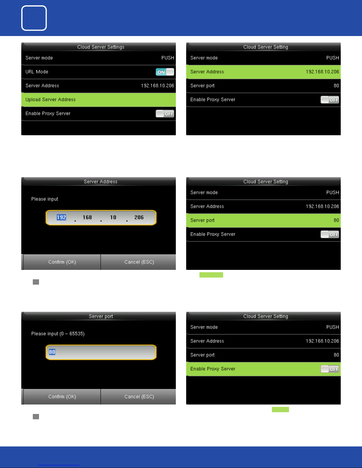
Once the “URL Mode” is “ON” you can upload the server address with “USB”.
Here you can change server port of the webserver by using the keypad and
press OK.
Here the server address is the IP address of the webserver.
Select Server port. It is as port which is used by the webserver.
Here you can change server port of the webserver by using the keypad and
press OK.
Here you can select the proxy server to be Enabled or not. If it is o as above
the proxy server will be disabled.
23
Page 24
3
COMMUNICATION
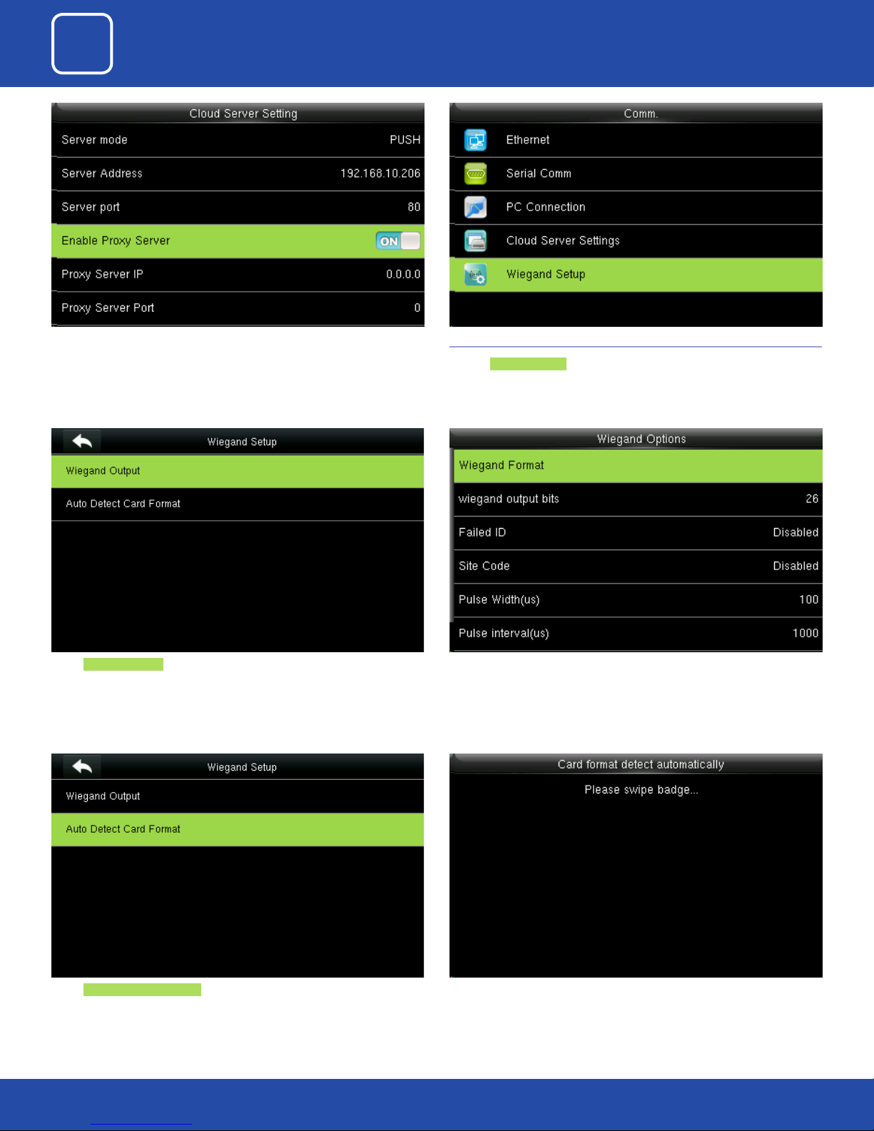
When you enable the proxy function, set the IP address and port number of
the proxy server. This option indicates whether to use a proxy IP address. You
may choose to enter the proxy IP address or the server address for Internet
access, whichever you like.
Select Wiegand Output
3.6 WIEGAND SETUP
Click on Wiegand Setup .
Here you can edit the Wiegand Output options you wish to apply.
Select Auto Detect Card Format
( This function is available only for standard RFID and HID proximity Cards )
Here you can swipe the multiple type of card with dierent Wiegand
formats.
24
Page 25
3
COMMUNICATION
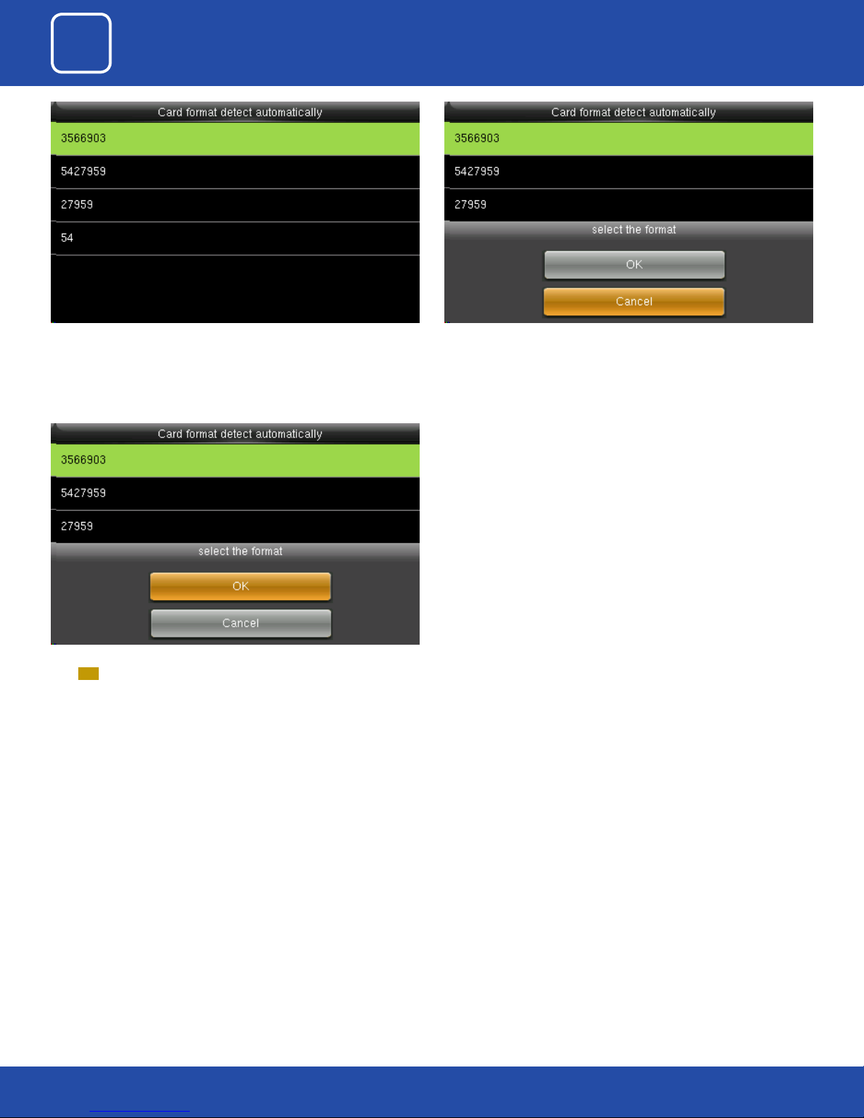
After you swipe the multiple card all the card with dierent Wiegand formats
will be displayed as above.
To select the particular Wiegand card format select that format and
press OK as shown above.
Here you can select the Wiegand format of the card you wish to choose to
register.
If you select “Cancel” that Wiegand format would not be selected.
25
Page 26

4
SYSTEM
Page 27
3
4
COMMUNICATION
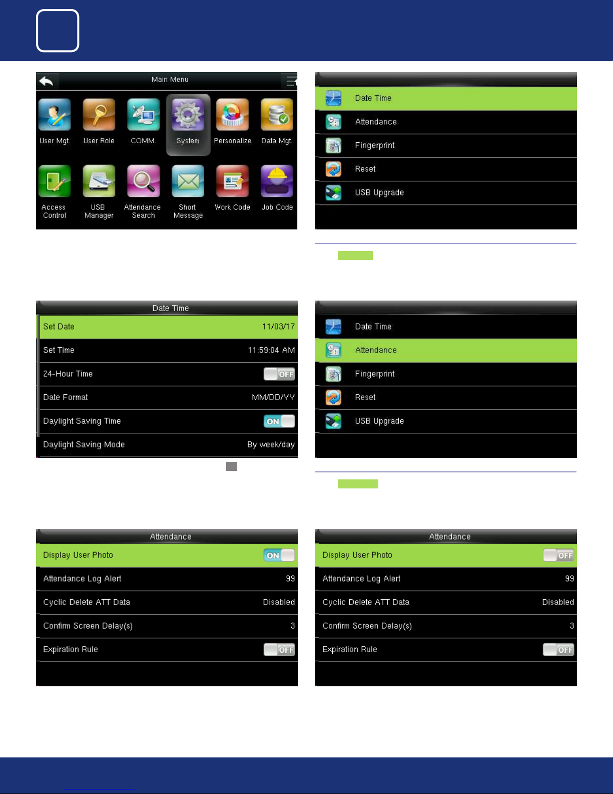
Select “System” . 4.1 DATE TIME
SYSTEM
Select Date Time .
Press select items. When the setting is completed, press OK to save the
setting and exit.
If you want to display the user photo you can select ON If you don’t want the user photo to be displayed select OFF as above.
4.2 ATTENDANCE
Select Attendance .
27
27
Page 28
3
4
COMMUNICATION
SYSTEM
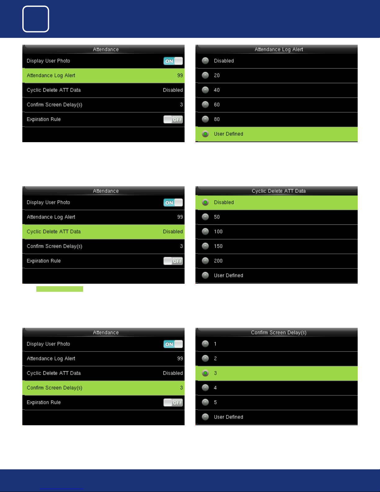
When the available space is insucient to store the specied number of
attendance records, the FFR terminal will automatically generate an alarm.
(Value scope: 1-99)
Select Cyclic Delete ATT Data. It species the maximum number of attend-
ance records that can be deleted at a time when the number of attendance
records reaches the upper limit.
You can change the value for attendance log alert from the image above.
This function can be disabled; otherwise, the value ranges from 1 to 999
28
28
The value ranges from 1s to 9s.The screen delay species the time for displaying the authentication result.
Page 29
3
4
COMMUNICATION
SYSTEM
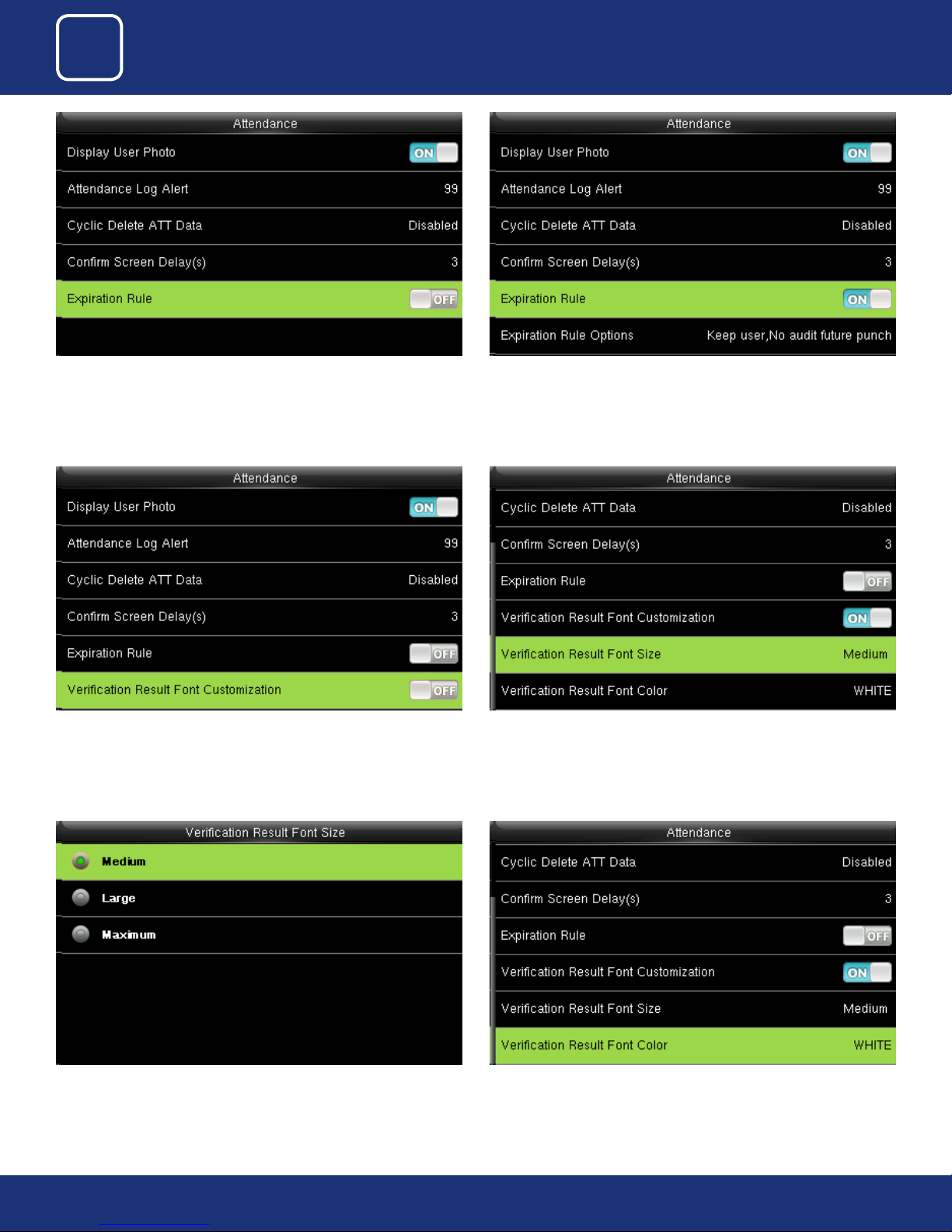
You can select the expiration rule as OFF if you don’t want to retain the user
information or to save attendance records.
Click on “Verication Result Font Customization” option from above and
press ON to change the Font Size.
You can select one of the three conditions:
• Retaining user information and not saving attendance records;
• Retaining user information and saving attendance records;
• Deleting user information
Here Default the font size would we be set to “Medium”.
Here you can change the Font size from “Medium” to “Large” or “Maximum”
you need to change.
Select “Verication Result Font Color” from above and press “OK”
29
29
Page 30
3
4
COMMUNICATION
SYSTEM
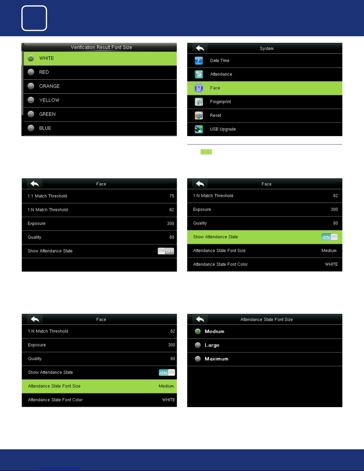
Here you can change the color of the font to dierent color you wish to
apply.
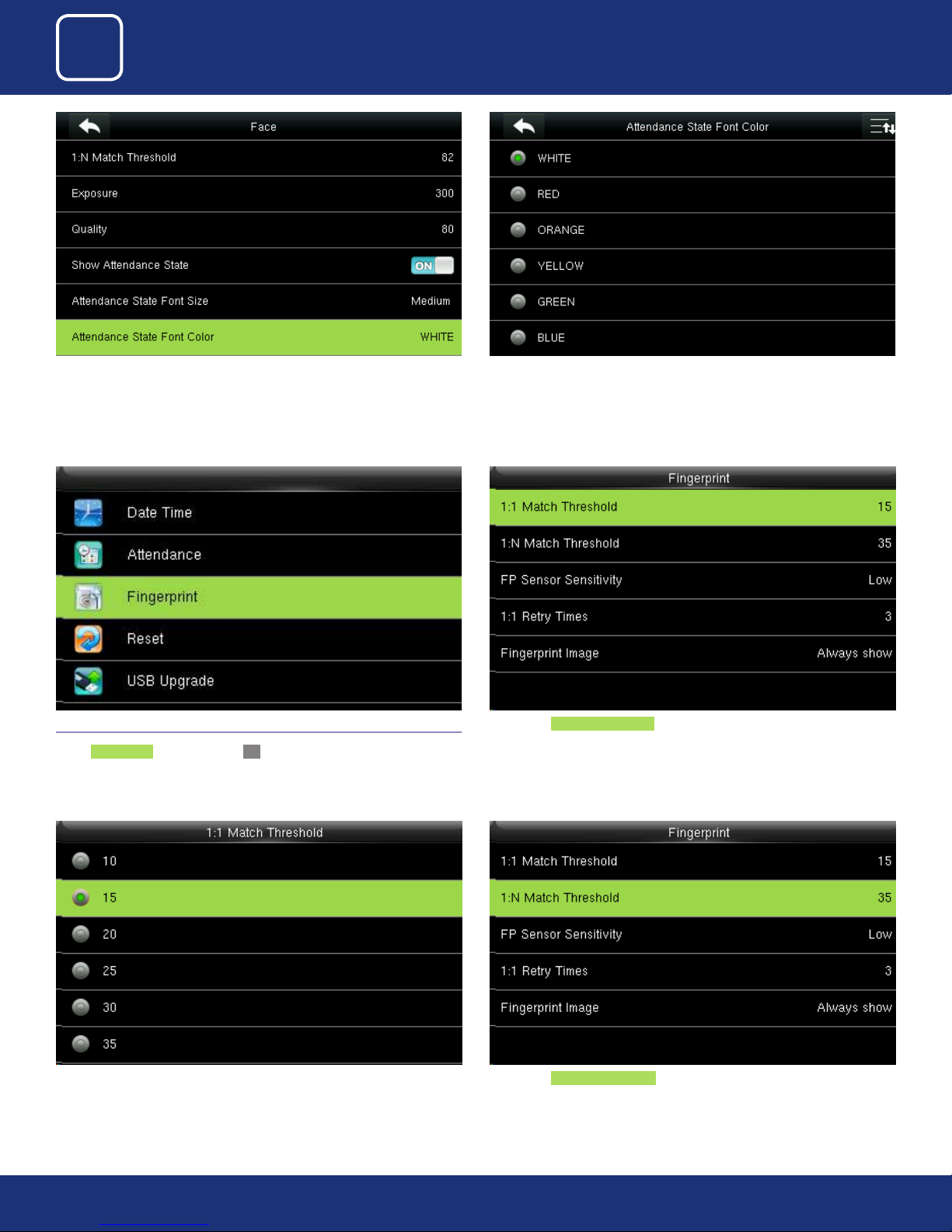
You can change the setting of face templates from the options above. Select “Show Attendance State” and turn “ON”. Once you turn “ON” you can
4.3 FACE
Select Face .
change the attendance state font size and color.
Select “Attendance State Font Size” Here you can change the font size to “Medium” , “Large” or “Maximum” you
wish to apply.
30
30
Page 31
3
4
COMMUNICATION
SYSTEM
Select “Attendance State Font Color”
4.3 FINGERPRINT
Select Fingerprint option and click OK.
You can change the font color to any color from the option above you wish
to apply
Here select 1:1 match threshold value is the similar of the ID+ngerprint
verication and the enrolled template.
You can change the value from the image above. The default will be selected as 15.
Here select 1:N match threshold value is the similarity of verication and the
enrolled template.
31
31
Page 32
3
4
COMMUNICATION
SYSTEM
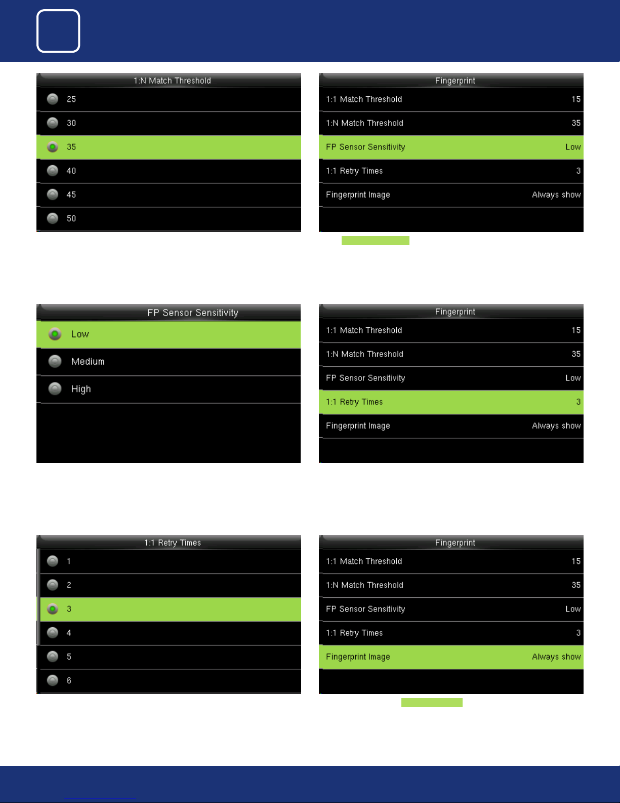
You can change the value from the image above.
The default will be set to 35
The default value Medium is recommended. You can set the sensitivity of
ngerprint collection to High when the response to nger scan lags in a dry
environment. When the usage environment is humid, you can set the sensitivity of ngerprint collection to Low if the ngerprint is dicult to identify.
Select FP sensor Sensitivity . It is used to set the sensitivity of ngerprint
collection.
This parameter is used to set the retry times in the event of failure of 1:1 verication or password verication due to an absence of ngerprint enrollment
or improper nger placement, so as to avoid repetitive operations.
You can change the retry times from the image above. The value ranges
from 1 to 6.
Here you can select the Fingerprint Image to be show. If you select this
option the display of the ngerprint image on the screen will be shown.
32
32
Page 33
3
4
COMMUNICATION
SYSTEM
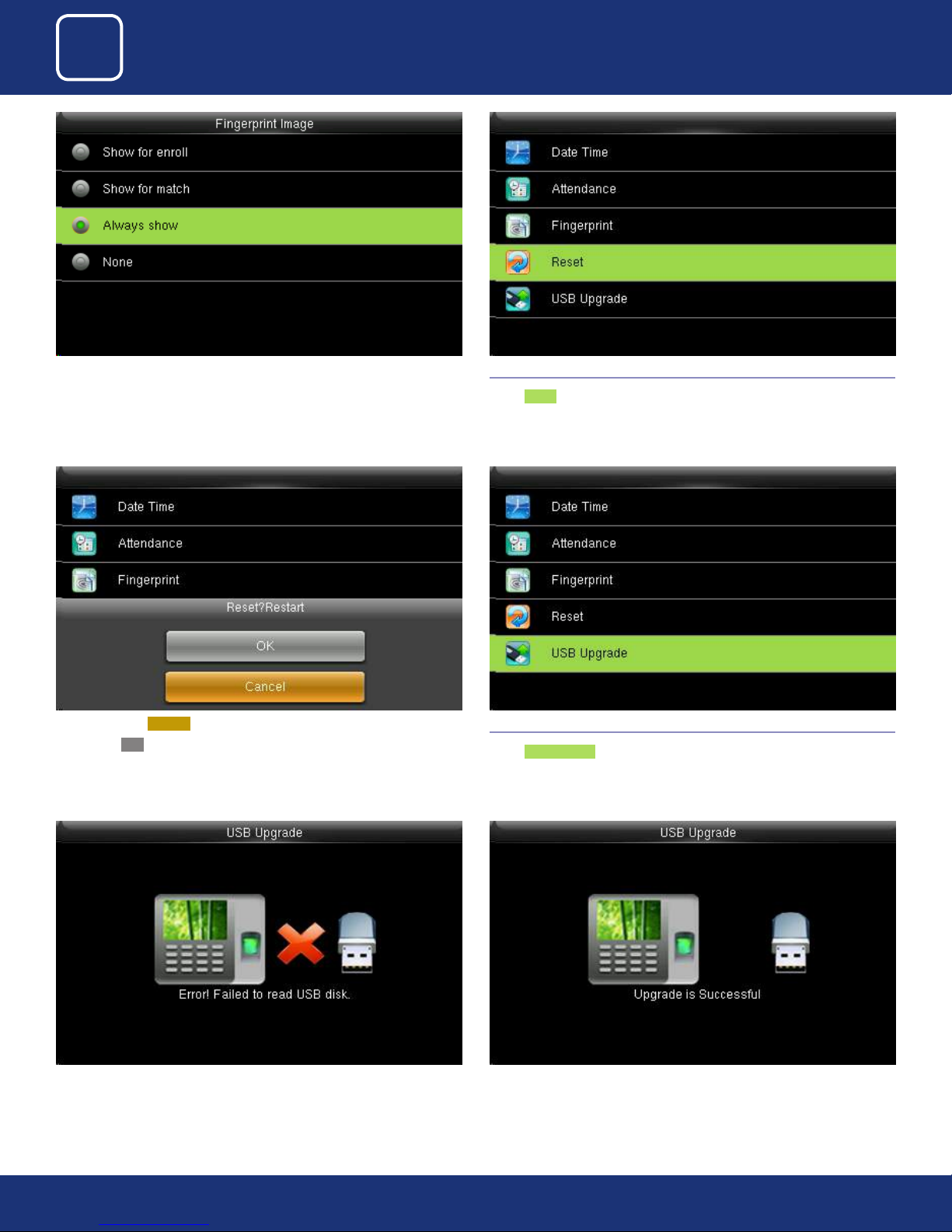
Here you can change the ngerprint image to be shown while enrolling or
to match and never
When you select Cancel it will go back to previous menu.
If you select OK it will rest the setting and restart the clock.
4.4 RESET
Select Reset .
4.5 USB UPGRADE
Select USB Upgrade .
If the USB is not readable or properly insert the image above will be displayed and you cannot be able to upgrade.
If the USB is readable or properly inserted the image above will be displayed
and you can be able to upgrade.
33
33
Page 34

5
PERSONALIZE
Page 35
3
4
5
COMMUNICATION
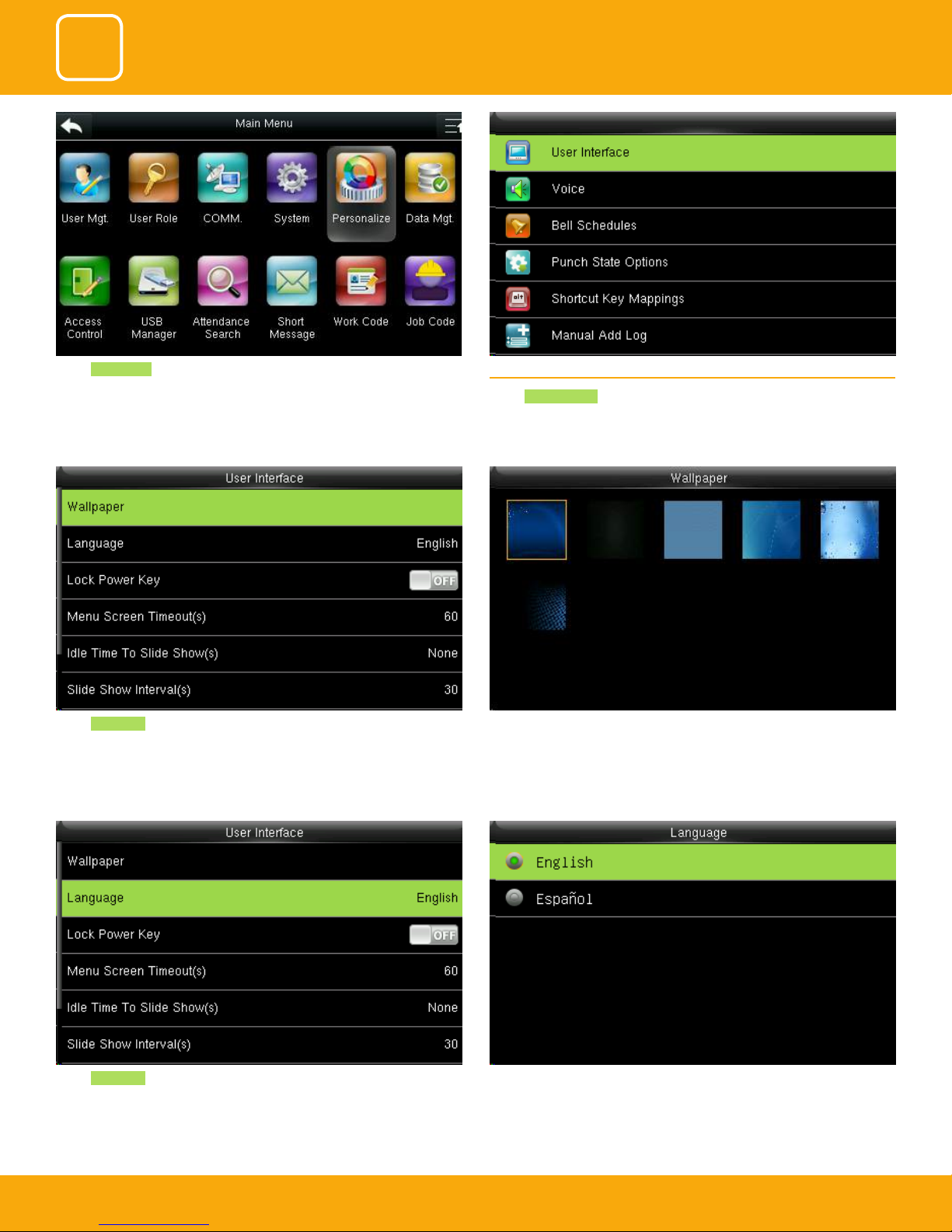
Select Personalize . 5.1 USER INTERFACE
SYSTEM
PERSONALIZE
Select User Interface .
Select Wallpaper .
Select Language .
If you select the wallpaper the dierent wallpaper will be displayed as shown
above and you can select any of the wallpaper you want to be displayed.
Here you can select the language you wish to display on the clock. The
options are English and Español (Spanish).
35
35
35
Page 36
3
4
5
COMMUNICATION
SYSTEM
PERSONALIZE
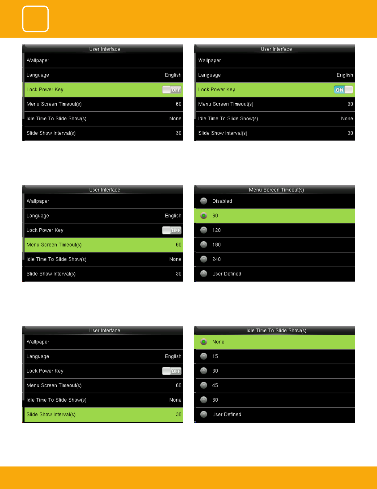
To prevent hostile power-o, select whether to lock power-o or not.
“disable”: the power is o 3 seconds after pressing power-o.
The device will display the main interface automatically when no operation
is performed on a menu within the menu timeout time
“Enable”: it is ineective after pressing power-o
This function can be disabled; otherwise, the value ranges from 60s to
99999s.
The advertisement picture is displayed when no operation is performed on
the main interface within the waiting time.
This function can be disabled; otherwise, the value ranges from 15s to 999s
36
36
36
Page 37
3
4
5
COMMUNICATION
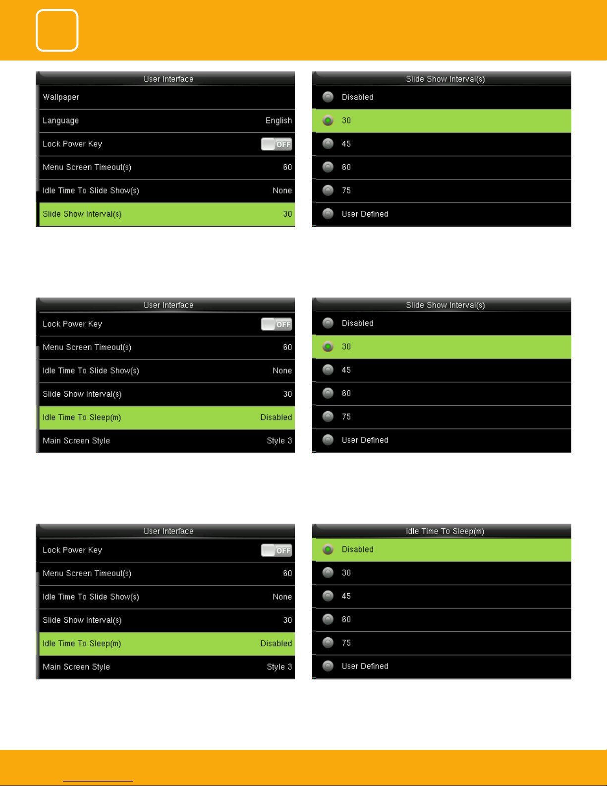
This parameter is used to set the picture cycle interval This parameter can be either disabled or ranges from 30 s to 999s.
SYSTEM
PERSONALIZE
This parameter is used to set the picture cycle interval This parameter can be either disabled or ranges from 30 s to 999s.
This parameter is used to specify a period after which the device is put in
sleep mode if no operation within this period. You can wake up the device
from sleep by pressing any key or touching the screen.
Numerical range in 30 minutes, the factory default for 30 minutes.
37
37
37
Page 38
3
4
5
COMMUNICATION
SYSTEM
PERSONALIZE
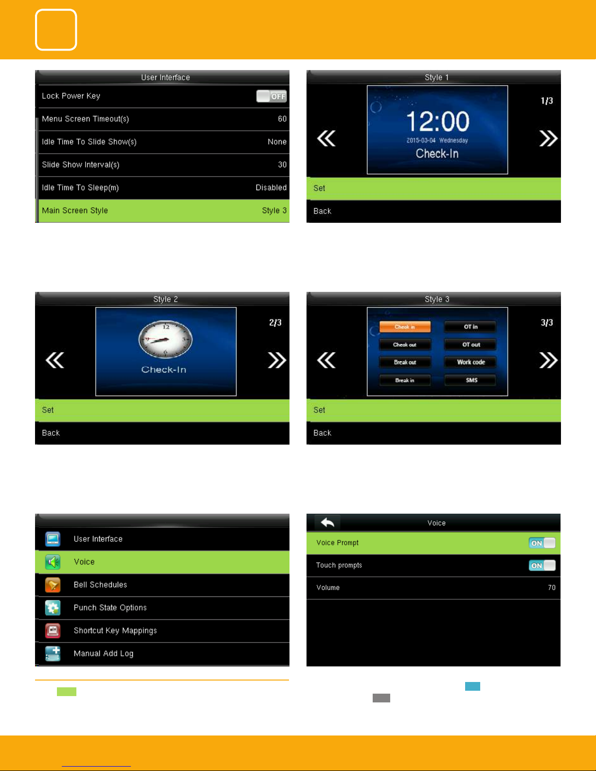
This is to set where and how the clock and status key are displayed on the
main screen.
Here is the “Style 2”. If you want this style press SET. And if you don’t want this
style simply to press back.
Here is the “Style 1”. If you want this style press SET. And if you don’t want
this style simply press back.
Here is the “Style 3”. If you want this style press SET. And if you don’t want this
style simply press back
5.2 VOICE
Select Voice .
Voice prompt: This parameter is used to set whether to play voice prompts
during the operation of the FFR terminal. Select ON to enable the voice
prompt, and select OFF to mute.
38
38
38
Page 39
3
4
5
COMMUNICATION
SYSTEM
PERSONALIZE
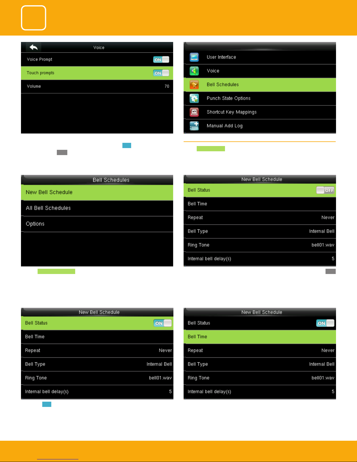
Touch prompt: - This parameter is used to set whether to generate beep
sound in response to every keyboard touch. Select ON to enable the beep
sound, and select OFF to mute
Click on New bell schedule. Click on bell status. It is whether you want the bell to enable. If you turn OFF
5.3 BELL SCHEDULES
Select Bell Schedules .
it will disable the bell.
If you turn ON it will enable the bell. The bell rings automatically when it is the specied time.
39
39
39
Page 40
3
4
5
COMMUNICATION
SYSTEM
PERSONALIZE
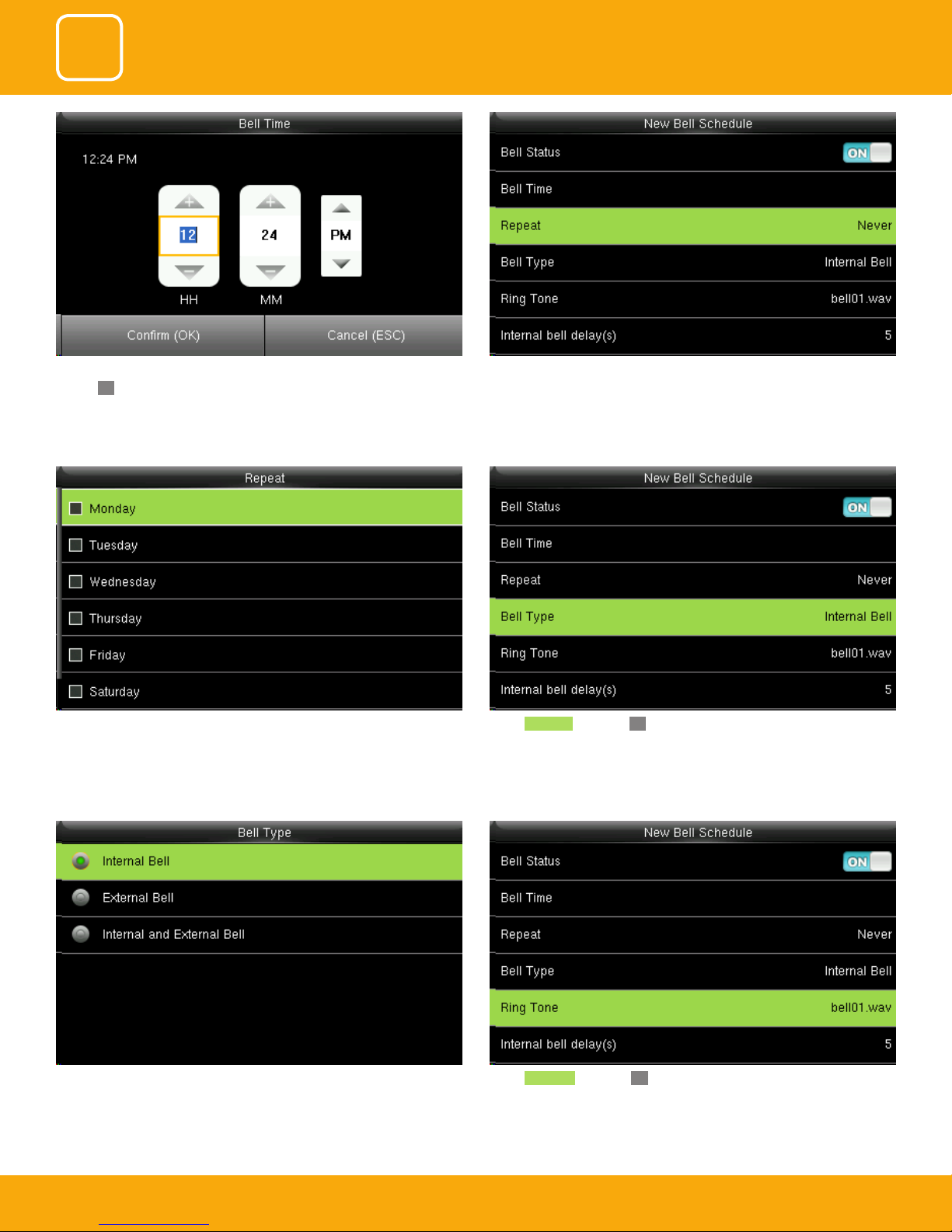
You can change the timings for the bell to ring using the keypad and then
conrmOK.
Here the bell is schedule at 12.24PM.
You can select any day of the week to repeat the ringtone. And if you don’t
want the ringtone to be repeated set to never.
The Repeat function species whether to repeat the ringtone
Select Bell Type and press OK.
Here you can select the bell type. If you want the ringtone to be played internally than select internal bell, for external select external bell and for both
select internal and external bell.
Select Ringtone and press OK.
40
40
40
Page 41
3
4
5
COMMUNICATION
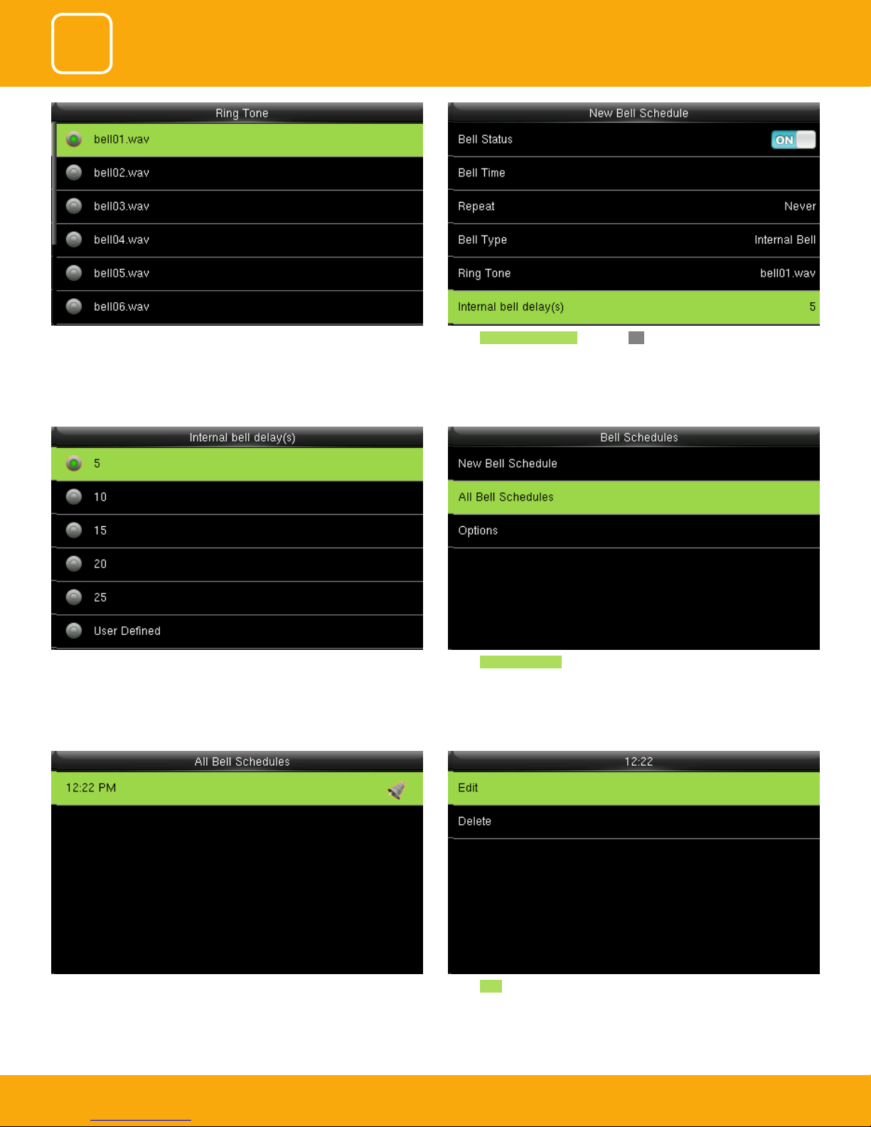
You can select any ringtone you want from the above options. Select Internal bell delay (s) and press OK.
SYSTEM
PERSONALIZE
It species the duration for ringtone playing.
You can edit the delay of the internal bell from the image above. It ranges
from 5 to 99 seconds.
Select New Bell Schedule. Select Edit to edit the bell schedules
Select All bell schedules .
41
41
41
Page 42
3
4
5
COMMUNICATION
SYSTEM
PERSONALIZE
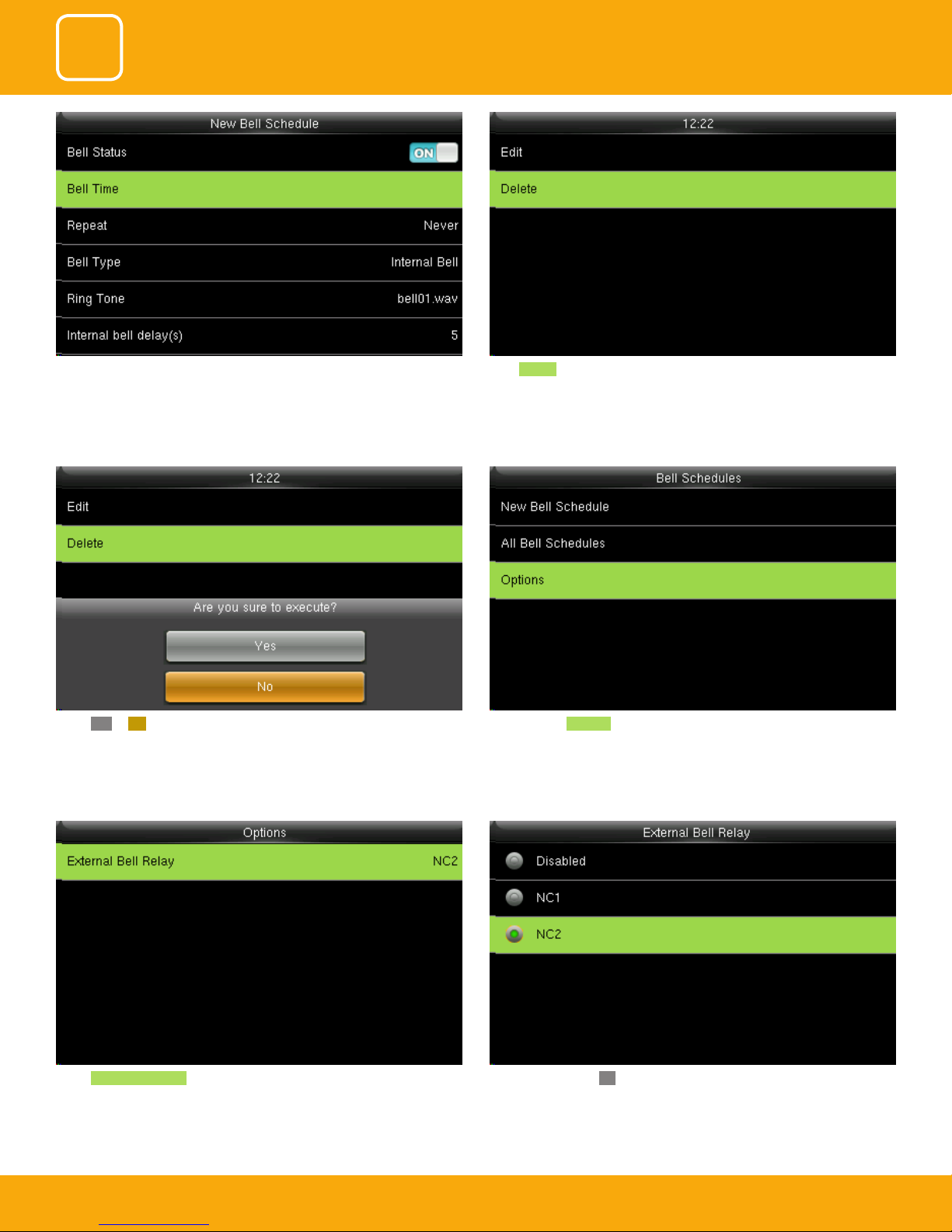
Select Item you wish to edit.
Press Delete the bell schedule.
Press to select Options .Select YES or NO.
Select External Bell Relay. Press to select, press OK to save and return.
42
42
42
Page 43
3
4
5
COMMUNICATION
SYSTEM
PERSONALIZE
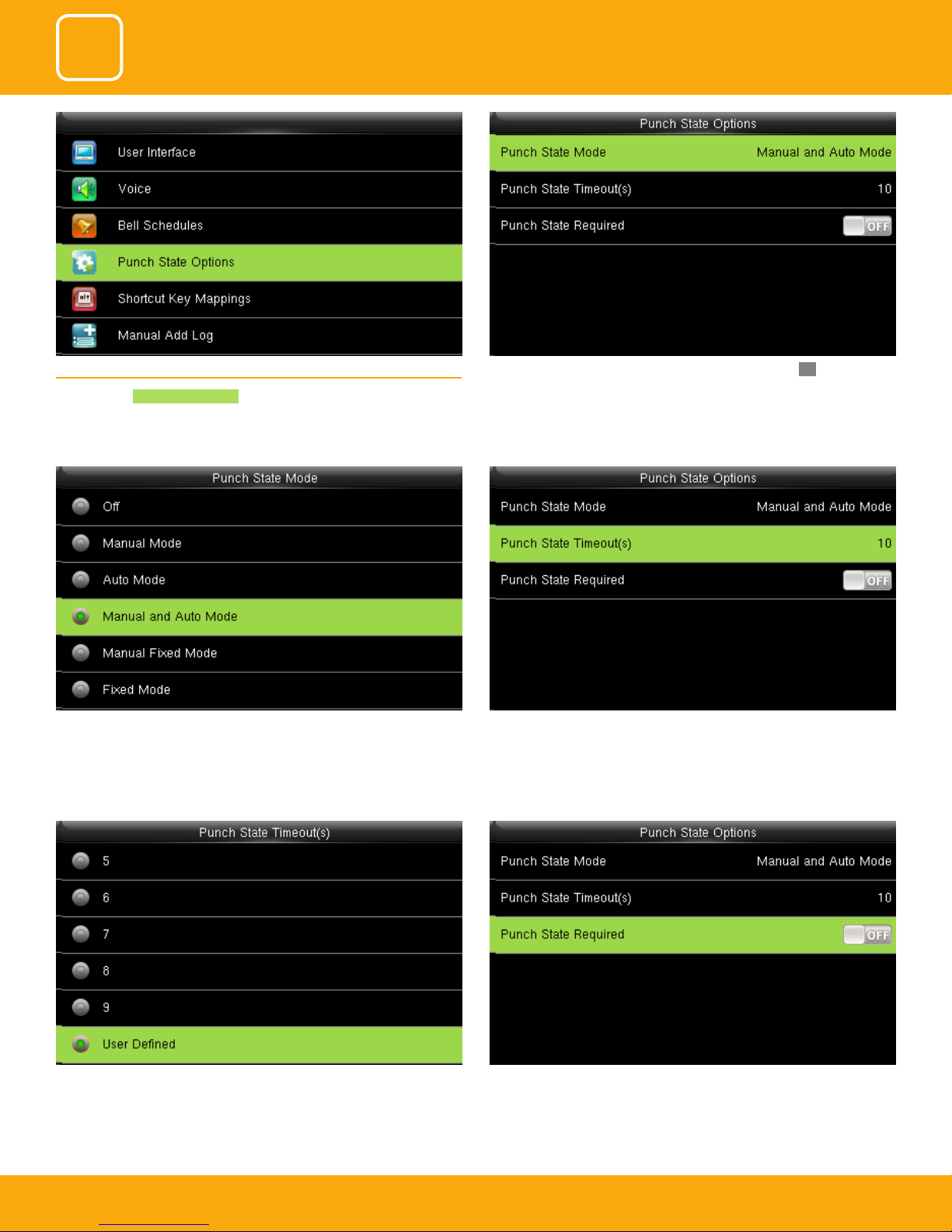
5.4 PUNCH STATE OPTIONS
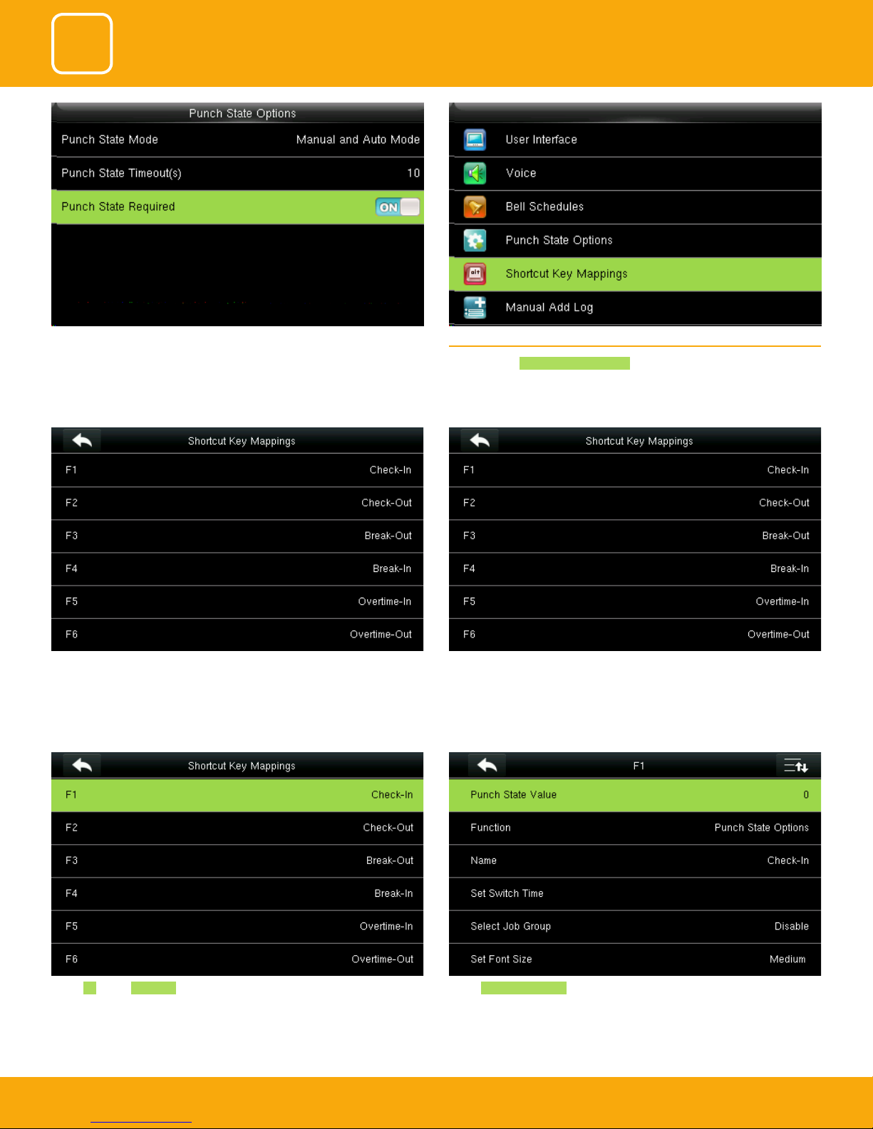
Press to select Punch State Options .
The main interface displays the status keys that can be switched automatically, and you are also allowed to switch status keys manually. A status key
you select manually will be switched according to the automatic switching
plan after it disappears upon a timeout.
Press to select items. When the setting is completed, press OK to save the
setting and exit.
Punch state timeout species the timeout period of the status key displayed
on the main interface.
You can change the punch state timeout from the image above. The
timeout ranges from 5 to 99 sec.
species whether the status of work attendance check must be selected
during authentication.
Here when its o it won’t be selected.
43
43
43
Page 44
3
4
5
COMMUNICATION
SYSTEM
PERSONALIZE
Species whether the status of work attendance check must be selected
during authentication.
When it’s on it will be selected.
These are standard attendance keys for Uface. You can select any keys you wish to use from the above menu
5.5 SHORTCUT KEY MAPPING
Press to select Shortcut Key Mappings .
Select F1 key as Check in. Select Punch State Value .
44
44
44
Page 45
3
4
5
COMMUNICATION
SYSTEM
PERSONALIZE
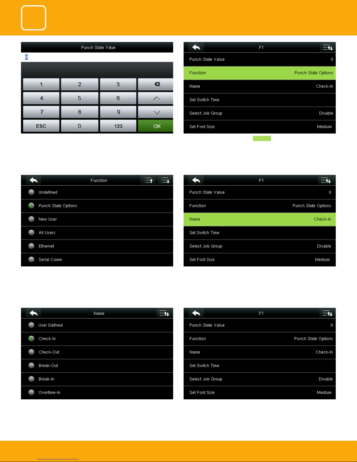
Here you can change the punch state value in the input screen by using the
keypad and press “OK”.
You can change the function for the keys above. Select name for F1
Here select punch state options as Function .
You can name the key for F1 you want from the options above. Here F1 is
selected as “Check in”.
Similarly, you can select the Job group or font size for that key you wish to
apply.
45
45
45
Page 46
3
4
5
COMMUNICATION
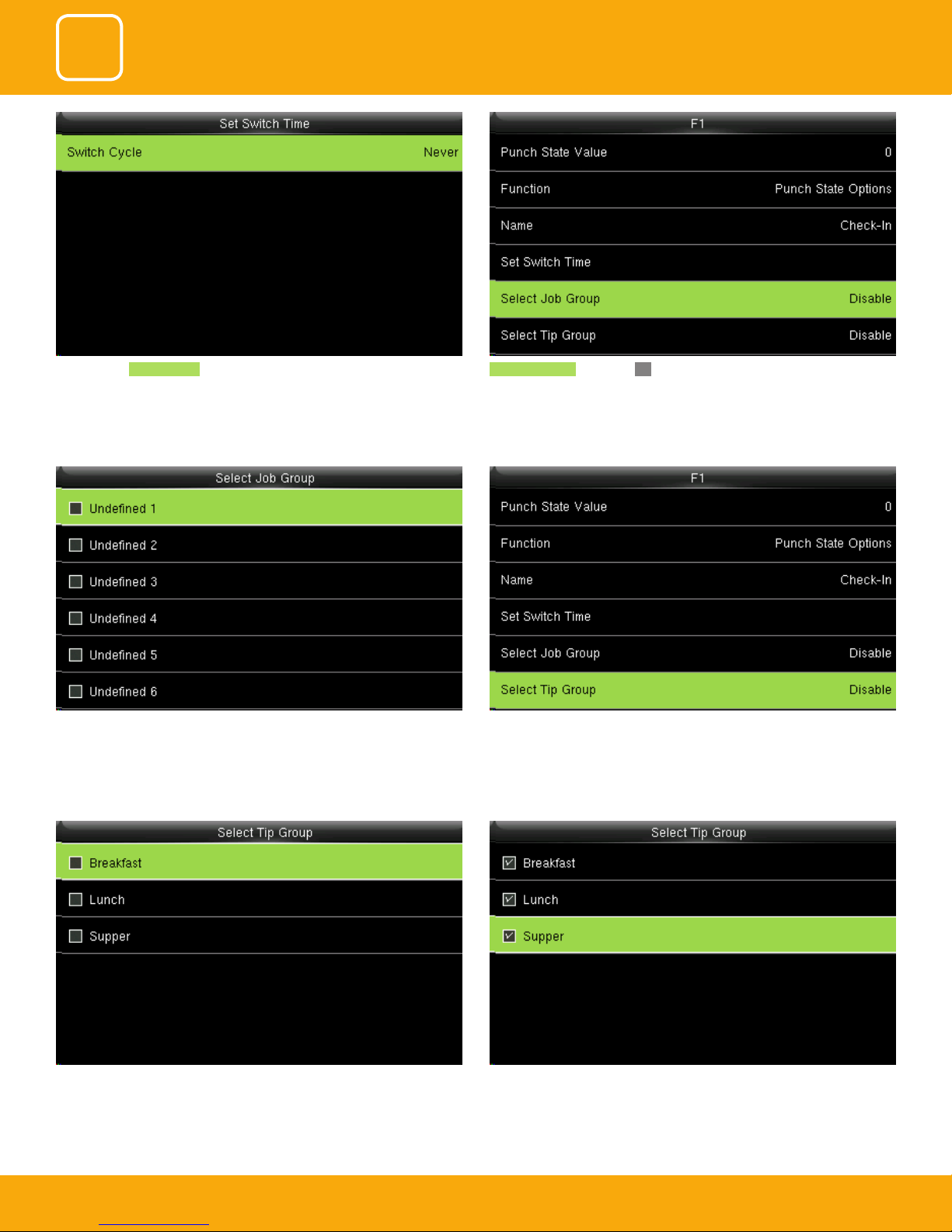
Here you can Switch Cycle Select job group and press OK. If you disable the job group will be disable
SYSTEM
PERSONALIZE
and it will not show on the screen
You can select any job group you want and you can name the job group by
using the keypad.
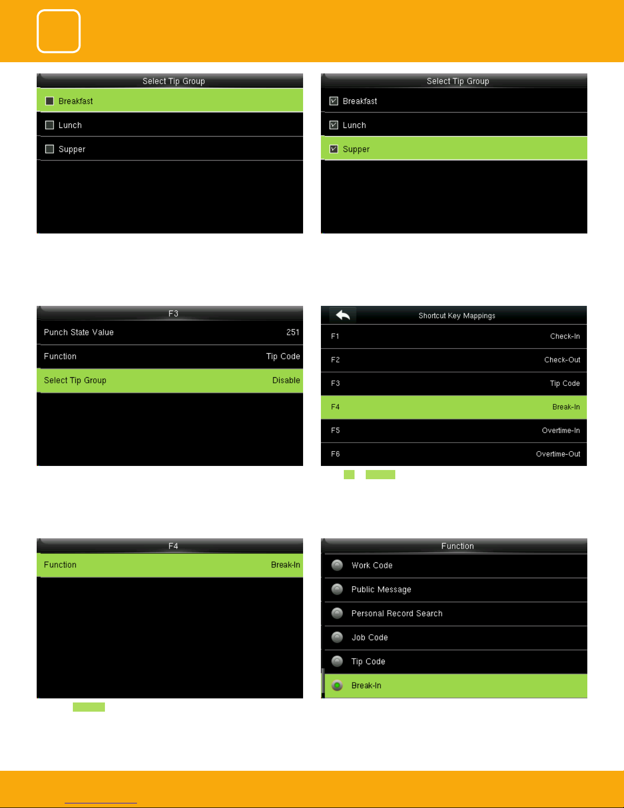
To enable the tip group you can select the tip group you wish to enter in
that group.
If you “Disable” the tip group the tip group will not be displayed on the
screen.
Here all the tip group has been selected as above.
46
46
46
Page 47
3
4
5
COMMUNICATION
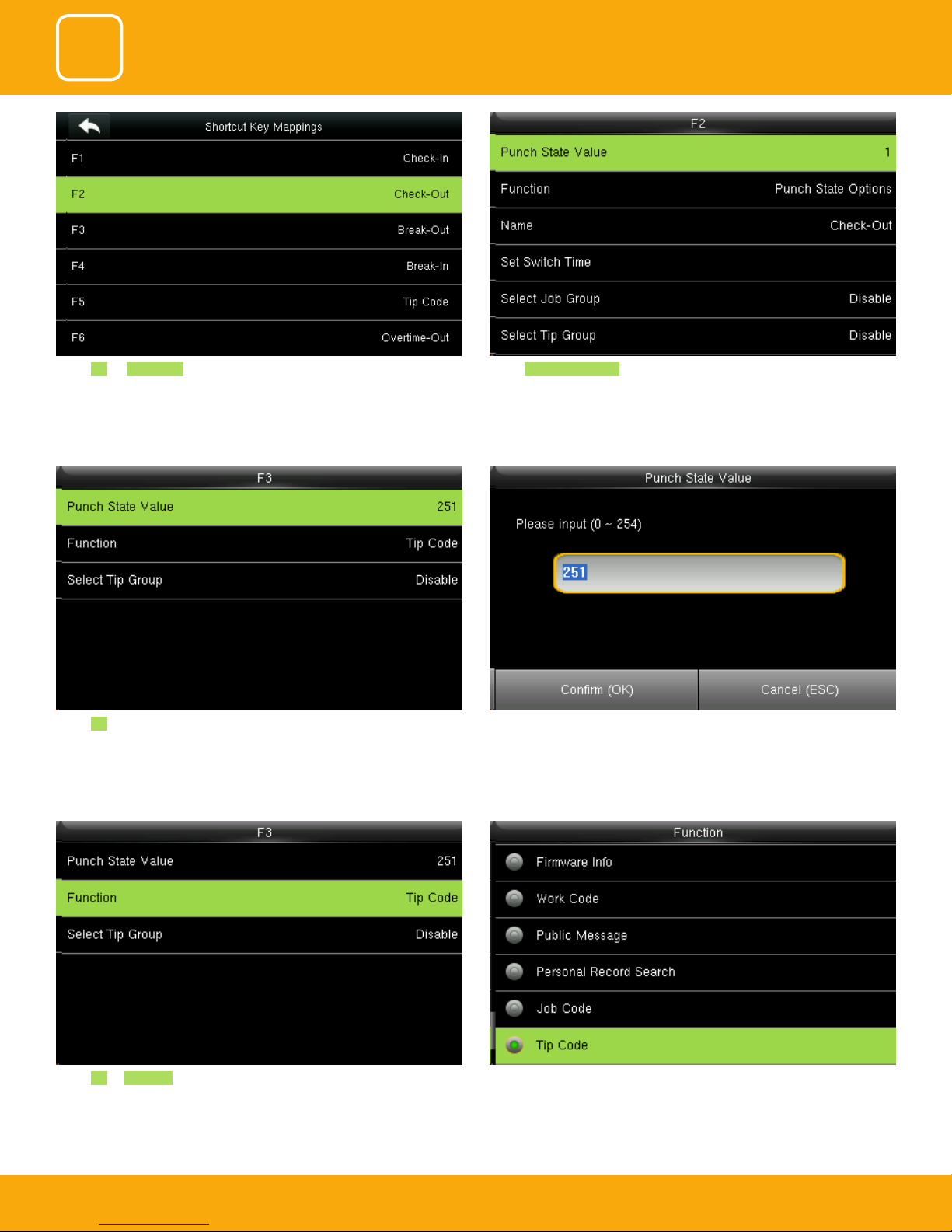
Select F2 as Check Out. Select Punch State Value.
SYSTEM
PERSONALIZE
Select F3 as “Tip code”.
Here the punch state value is set to 251
For more details refer to paragraph 13.
Select F3 as Tip code. For more details refer to No 13. You can change the function for that key from the image above.
You can change the value of the punch state by changing the value in the
input screen with the help of keypad.
47
47
47
Page 48
3
4
5
COMMUNICATION
SYSTEM
PERSONALIZE
You can select the tip group you want. Here all the tip group are selectedHere the tip group is disable and no tip group has been selected.
When you select all the tip group the select tip group will display as “All
group”.
the main screen.
Select F4 as Break-In.
You can change the functions from above.Select the Function Break-In for F4 and the F4 key will display as Break-In on
48
48
48
Page 49
3
4
5
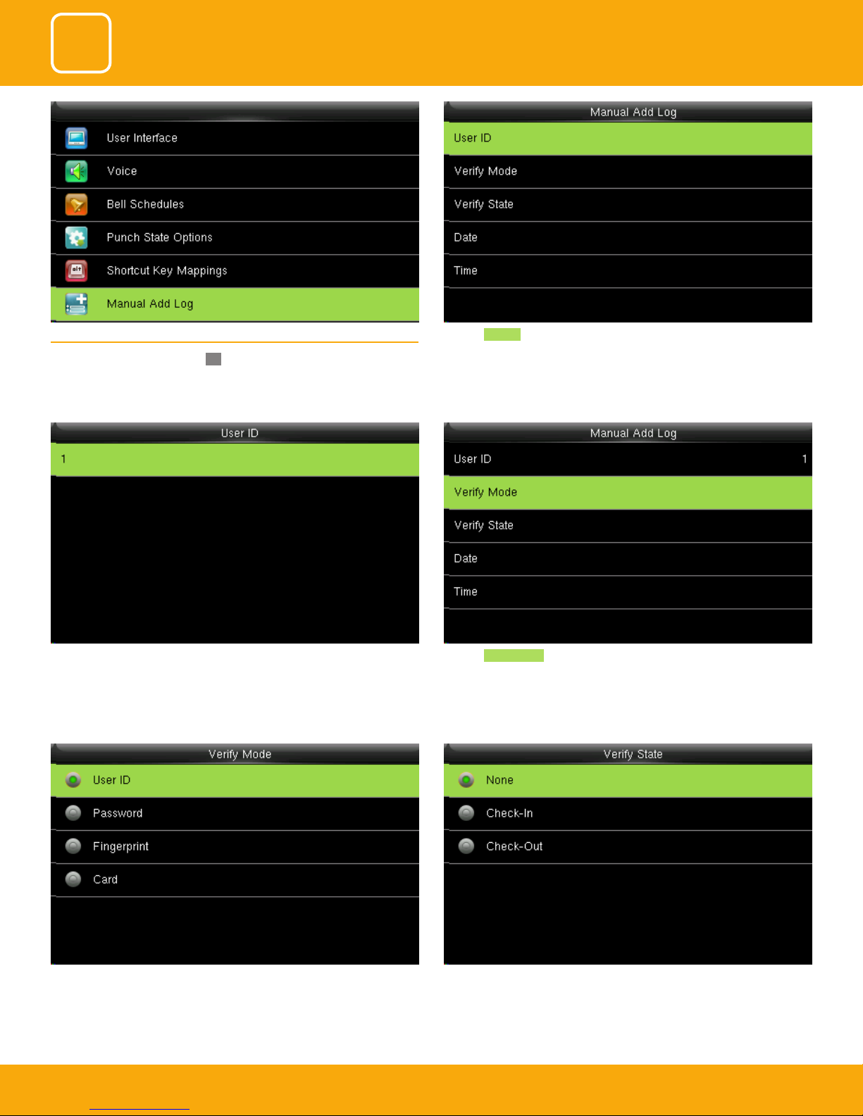
Select annual add log and press OK.
COMMUNICATION
SYSTEM
PERSONALIZE
Click on User ID 5.6 MANUAL ADD LOG
Here you can select any verication mode you want the user to get veried.
The user can verify themselves either with their UserID, Fingerprint, Password
or Card/Badge.
Click on Verify mode. The user id is displaying as 1.
Select verify state as none. In this all the user from all state can verify themselves.
If you verify the state the user from that state can only verify themselves.
49
49
49
Page 50
3
4
5
COMMUNICATION
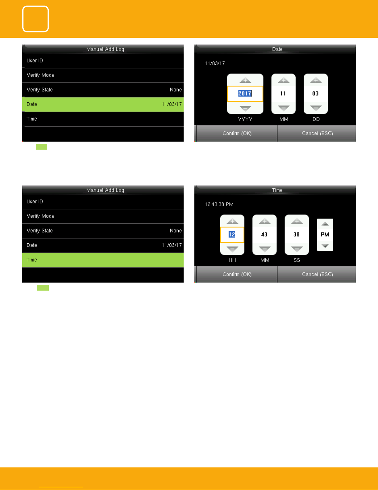
Select Date . You can set the date by using the keypad. Here the date is set to 11/03/2017.
SYSTEM
PERSONALIZE
Select Time .
You can set the “Time” by using the keypad. Here the time is set to 12hr,
43min, 38ss.
50
50
50
Page 51

6
DATA MANAGEMENT
Page 52
3
4
5
6
COMMUNICATION
DATA MANAGEMENT
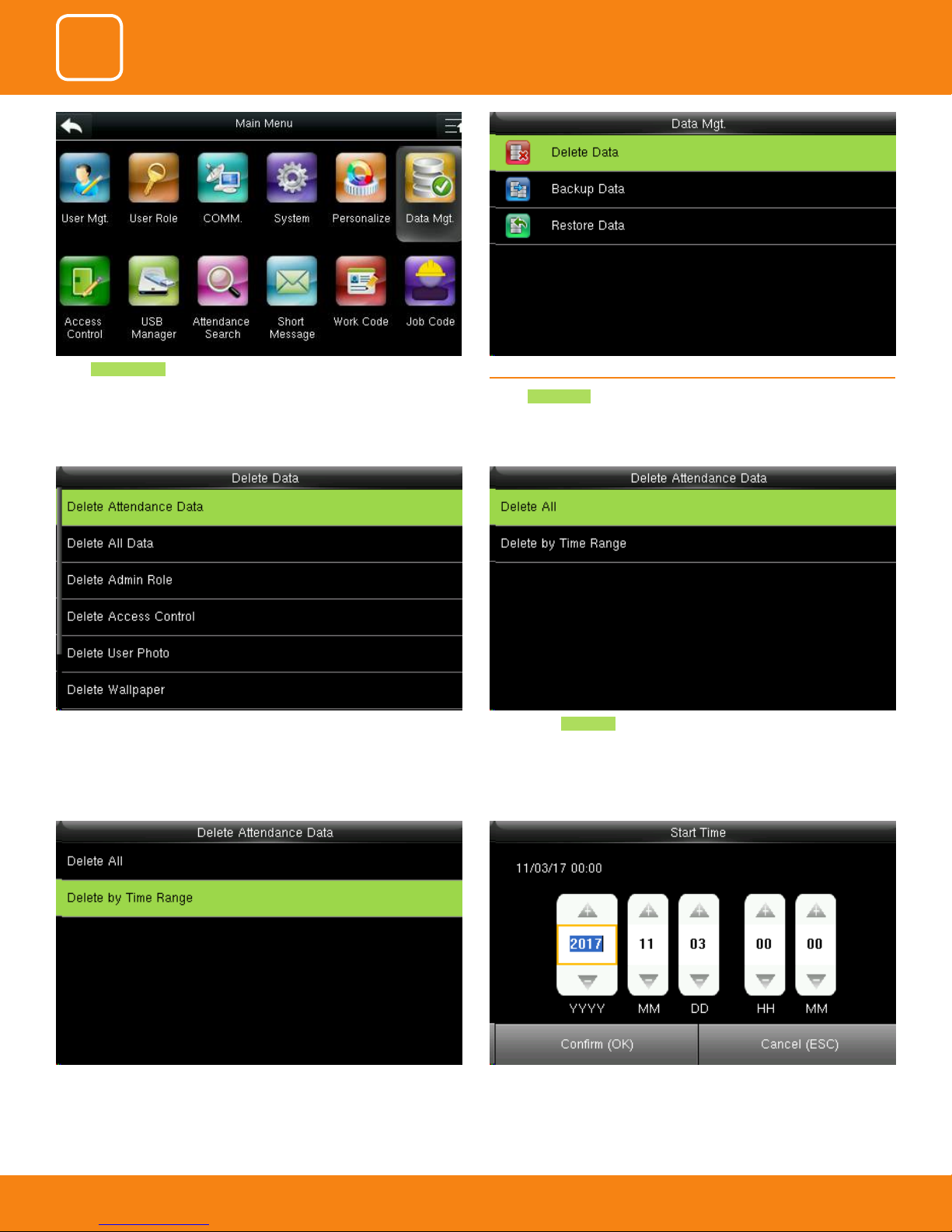
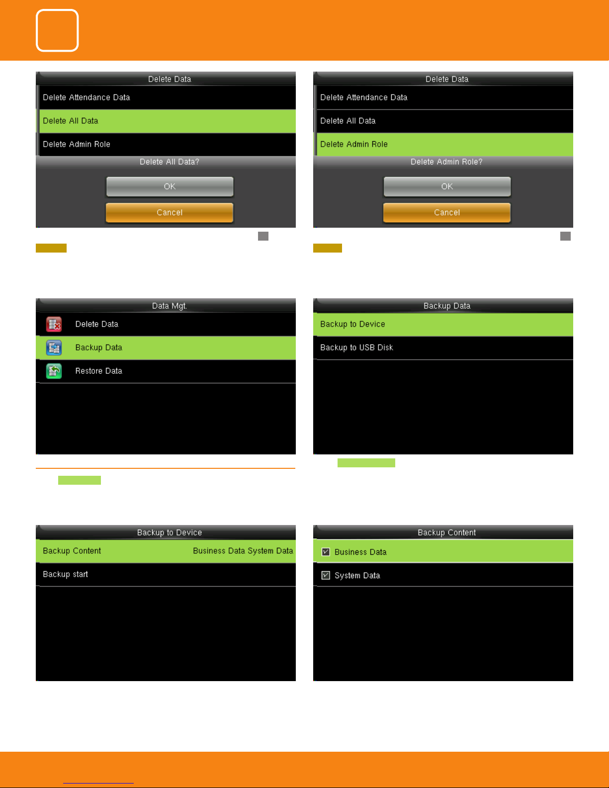
Select Data Manager . 6.1 DELETE DATA
SYSTEM
PERSONALIZE
Select Delete Data .
It will delete the attendance records When select Delete All it will delete all the attendance records
You can delete the attendance data by Time Range too. To selete by time range you can select the time you want the data to be
deleted.
It will delete the data for that specic time you selected.
52
52
52
52
Page 53
3
4
5
6
COMMUNICATION
DATA MANAGEMENT
SYSTEM
PERSONALIZE
Here you can delete all data by selecting delete all data and press OK.
CANCEL will take you back to previous screen.
6.2 BACKUP DATA
Select Backup Data .
Here you can delete admin role by selecting delete admin role and press OK.
CANCEL will take you back to previous screen
Select Backup to Device to back up the content from the device.
items.
53
53
53
53
You can select the content you want to backup.Select the local conguration items to be back upped to device the selected
Page 54
3
4
5
6
COMMUNICATION
DATA MANAGEMENT
SYSTEM
PERSONALIZE
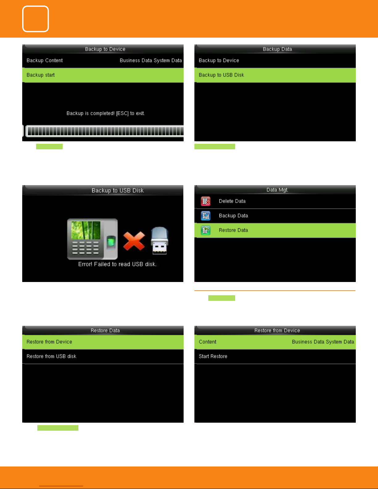
Select Backup Start and once the bacup is completed the above image will
be displayed.
If the usb is not properly inserted the above scdreen will be displayed.
You can either change the USB or insert it properly again.
Backup to USB Disk , the operations are similar to those performed to Backup
to Device.
6.3 RESTORE DATA
Select Restore Data .
Select Backup from Device .
Select the local conguration items to be restored and save the selected
items.
54
54
54
54
Page 55
3
4
5
6
COMMUNICATION
DATA MANAGEMENT
SYSTEM
PERSONALIZE
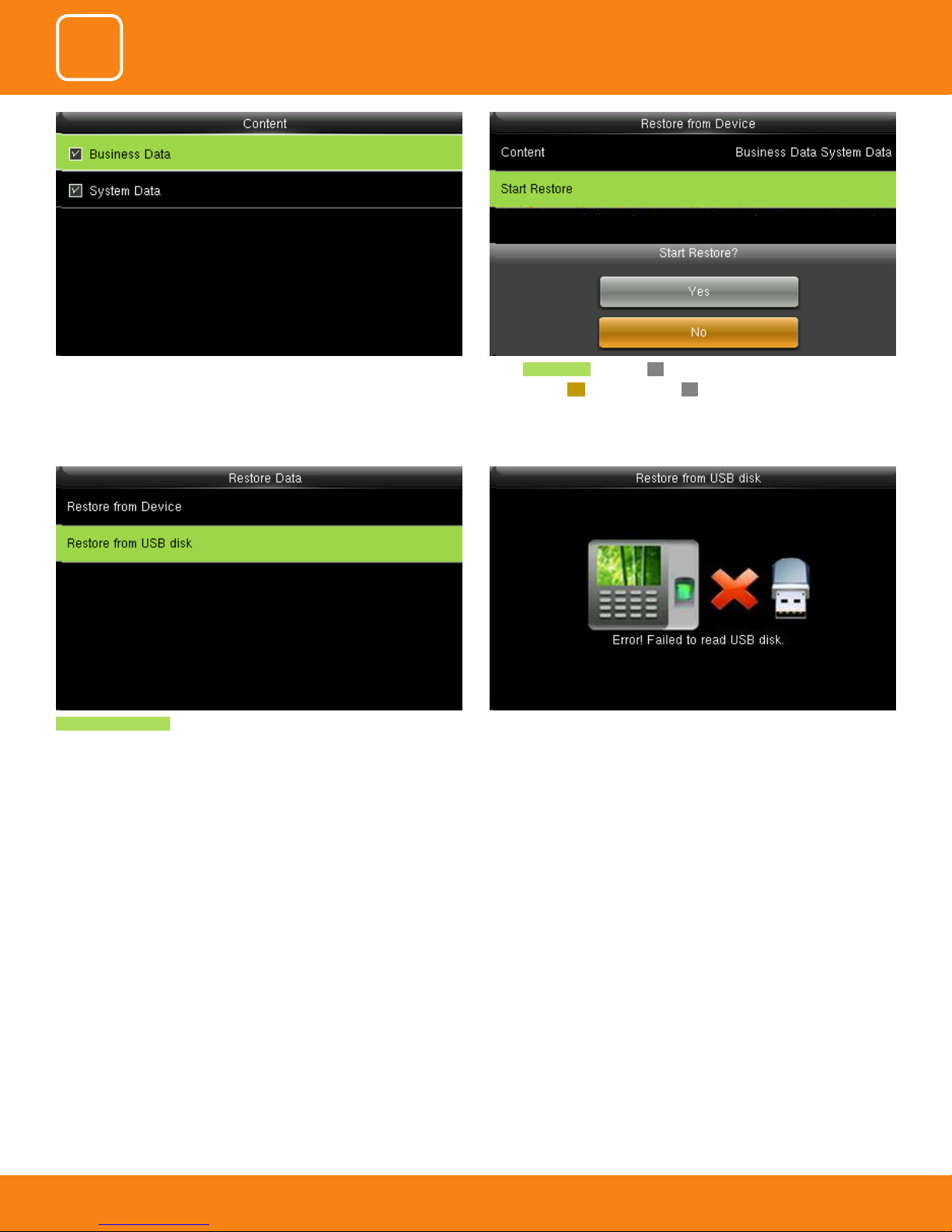
You can select the content you want to restore.
Restore from USB Disk the operations are similar to those performed to
restore from Device.
select Start Restore and press OK.
select Yes or NO Device and press OK.
If the USB disk is not properly inserted the above scdreen will be displayed.
You can either change the USB or insert it properly again.
55
55
55
55
Page 56

7
ACCESS CONTROL
Page 57
3
4
5
6
7
COMMUNICATION
DATA MANAGEMENT
ACCESS CONTROL
SYSTEM
PERSONALIZE
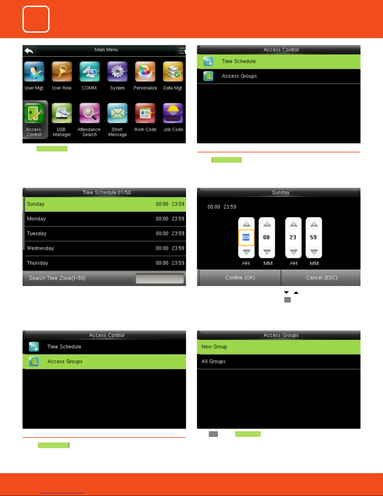
Select Access Control .
Use numeric keys to search for a time period in the range from 1 to 50.
Select the item to be set.
7.1 TIME SCHEDULE
Select Time Schedule .
Press / to select a time option and press / to set
time. After setting a period of time, press OK to save the setting and exit
Select Access Groups .
57
57
57
57
57
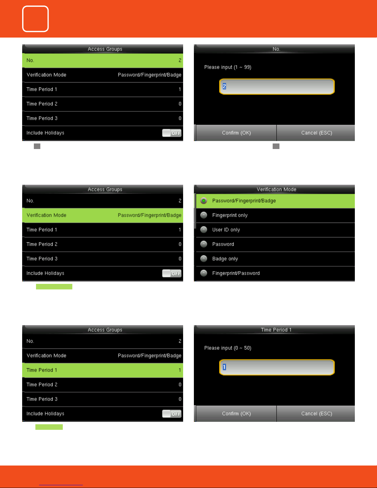
Press OK to add New Group 7.2 ACCESS GROUP
Page 58
3
4
5
6
7
COMMUNICATION
DATA MANAGEMENT
ACCESS CONTROL
SYSTEM
PERSONALIZE
Enter the No. using keypad and press OK.Press OK.
Select Verication Mode . Select Verication Mode, you wish to apply and save and return.
select Time Period 1. Enter the No. using keypad.
58
58
58
58
58
Page 59
3
4
5
6
7
COMMUNICATION
DATA MANAGEMENT
ACCESS CONTROL
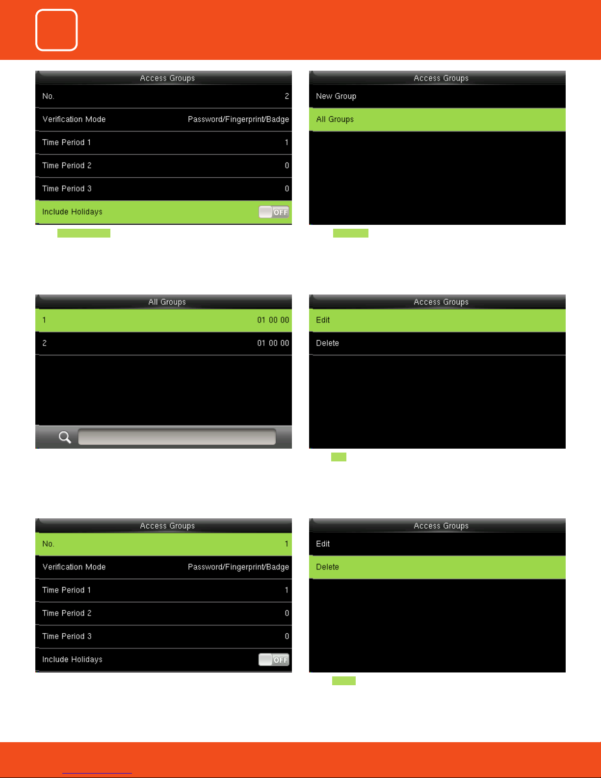
Select Include Holidays to enable the item Select All Groups .
SYSTEM
PERSONALIZE
Select one of All Groups. Select Edit .
The No. cannot be modied, and the other operations are similar to those
performed to add a New Groups. Press left arrow on the screen to return
select Delete .
59
59
59
59
59
Page 60
3
4
5
6
7
COMMUNICATION
DATA MANAGEMENT
ACCESS CONTROL
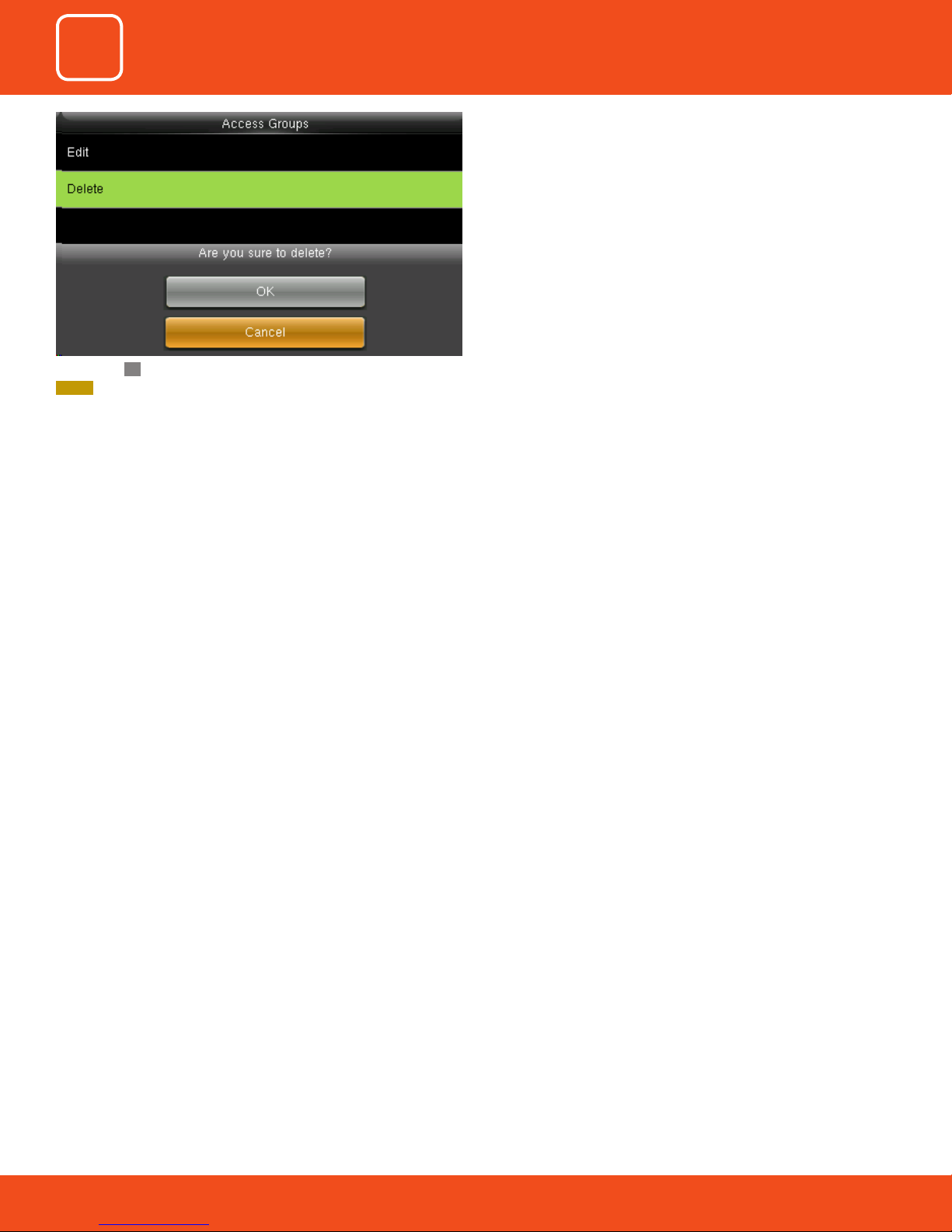
If you select OK it will delete all the access groups and when you select
Cancel it will take you to previous screen without deleting any access
groups.
SYSTEM
PERSONALIZE
60
60
60
60
60
Page 61

8
USB MANAGER
Page 62
3
4
5
6
7
8
COMMUNICATION
DATA MANAGEMENT
ACCESS CONTROL
USB MANAGER
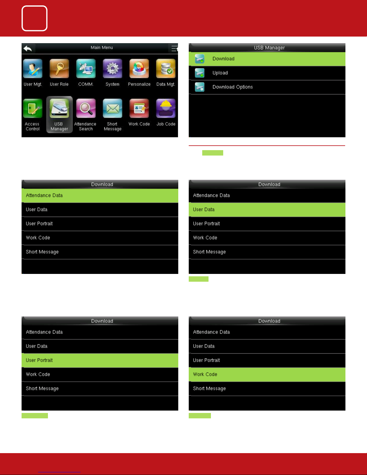
Go to Menu and select USB Manage. 8.1 DOWNLOAD
SYSTEM
PERSONALIZE
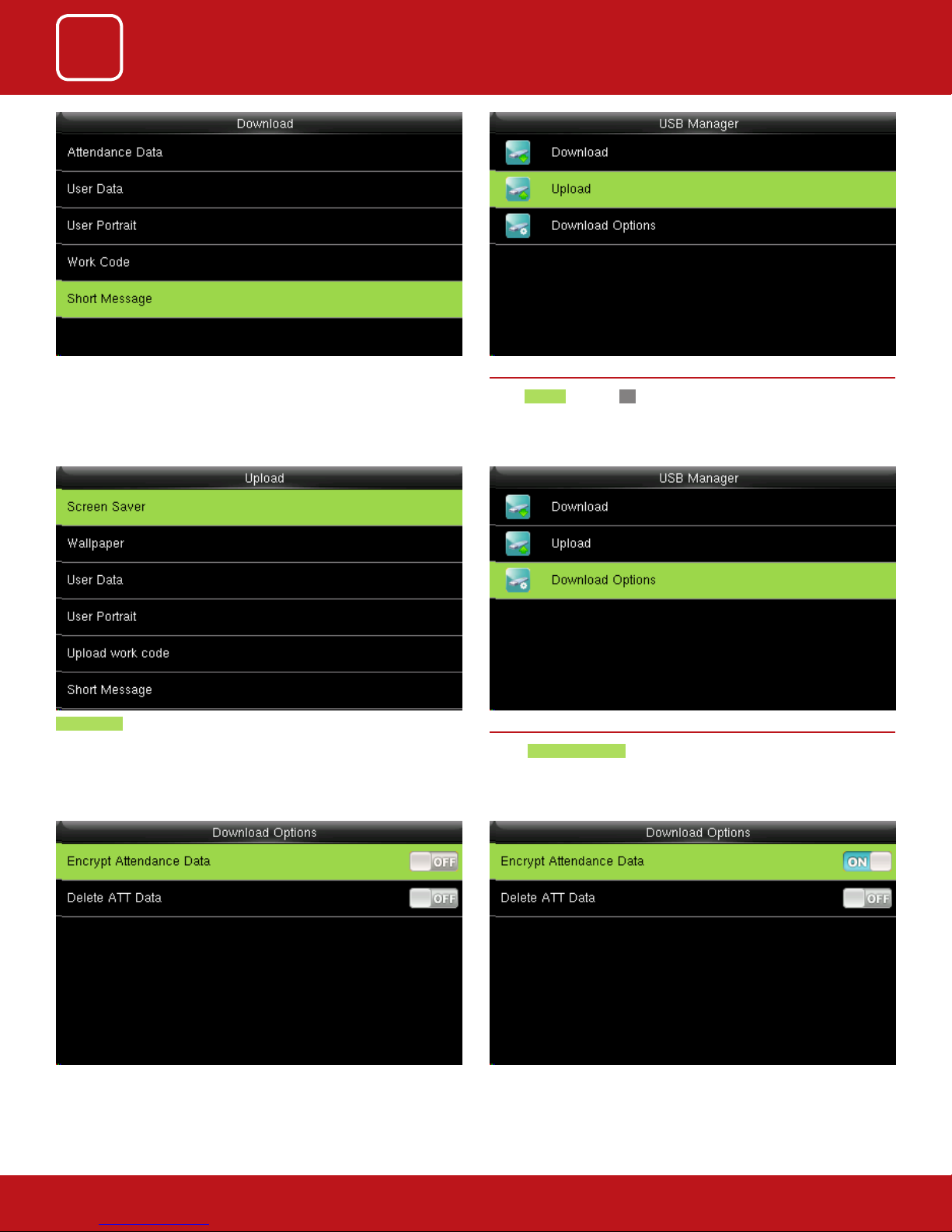
Select Download.
Select the items you want to download.
Here when we select the “Attendance Data” it will import all the attendance
data from the FFR terminal to USB disk
disk.
User data will import all the user information, ngerprints and facial images
from the FFR terminal to a USB disk
Work code will save the work IDs on the device to a USB drive User Portrait will Import the employees’ photos from the terminal to a USB
62
62
62
62
62
62
Page 63
3
4
5
6
7
8
COMMUNICATION
DATA MANAGEMENT
ACCESS CONTROL
USB MANAGER
SYSTEM
PERSONALIZE
The short message will be displayed by the administrator and will be import
from terminal to USB disk.
Screen saver will Upload the JPG documents with “ad_” as initial letters of
document names stored in a USB disk to the terminal. After the upload,
these pictures can be displayed on the initial interface of the terminal.
8.2 UPLOAD
Select Upload and press OK.
In Upload it will upload all the data from USB disk to terminal.
8.3 DOWNLOAD OPTIONS
Select Download Options .
Select items from the options above. When the setting is completed, select
to save the setting and exit.
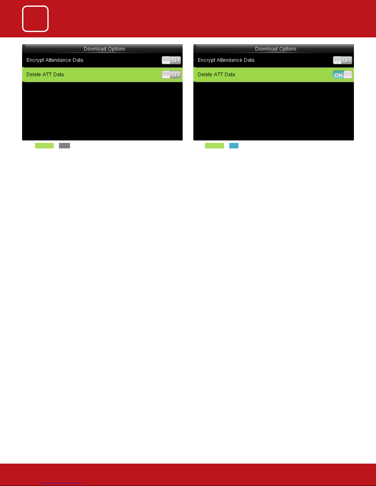
This will download all the encrypted attendance data of the employee.
63
63
63
63
63
63
Page 64
3
4
5
6
7
8
COMMUNICATION
DATA MANAGEMENT
ACCESS CONTROL
USB MANAGER
If the ATT data is OFF it wont downlad any data as the function is diabled. If the ATT data is ON it will downlad the data as the function is enabled.
SYSTEM
PERSONALIZE
64
64
64
64
64
64
Page 65

9
ATTENDANCE SEARCH
Page 66
3
4
5
6
7
8
9
COMMUNICATION
DATA MANAGEMENT
ACCESS CONTROL
ATTENDANCE SEARCH
USB MANAGER
SYSTEM
PERSONALIZE
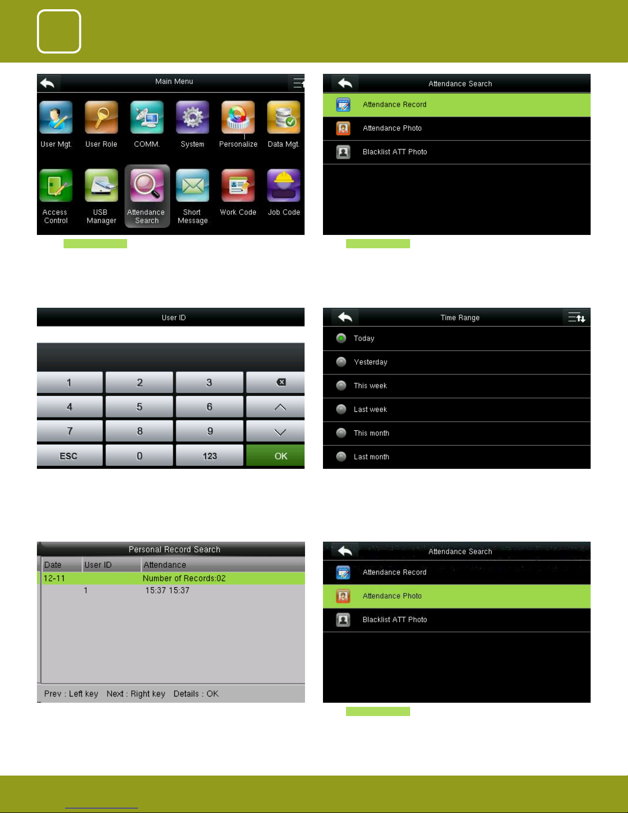
Select Attendance Search
Enter the “User ID” of the user you wish to see the attendance record
Select Attendance Record
Here you can select the time range you wish to see the record of that user.
The dierent options are available as shown above.
The records in accordance with the conditions will be displayed as above.
Select Attendance Photo
66
66
66
66
66
66
66
Page 67

3
4
5
6
7
8
9
COMMUNICATION
DATA MANAGEMENT
ACCESS CONTROL
ATTENDANCE SEARCH
USB MANAGER
SYSTEM
PERSONALIZE
Enter the “User ID” of the user you wish to see the attendance photo.
Select Blacklist ATT Photo .
Here you can search for the pictures of the user which are blacklisted in the
attendance record.
Here you can select the time range you wish to see the record of that user.
The dierent options are available as shown above.
67
67
67
67
67
67
67
Page 68

10
SHORT MESSAGE
Page 69
3
4
5
6
7
8
9
10
COMMUNICATION
DATA MANAGEMENT
ACCESS CONTROL
ATTENDANCE SEARCH
USB MANAGER
SHORT MESSAGE
SYSTEM
PERSONALIZE
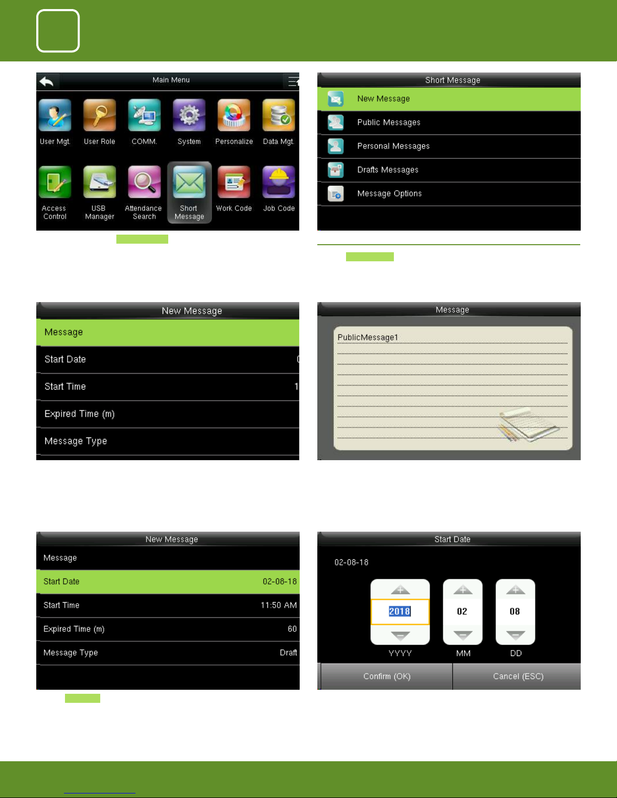
Go to Menu and select Short Message .
Click on the “Message” option as shown above.
10.1 NEW MESSAGE
Click on New Message .
After you click on “Message” the above screen will appear in which you can
type the message with the help of keypad you wish to send.
69
69
69
69
69
69
69
69
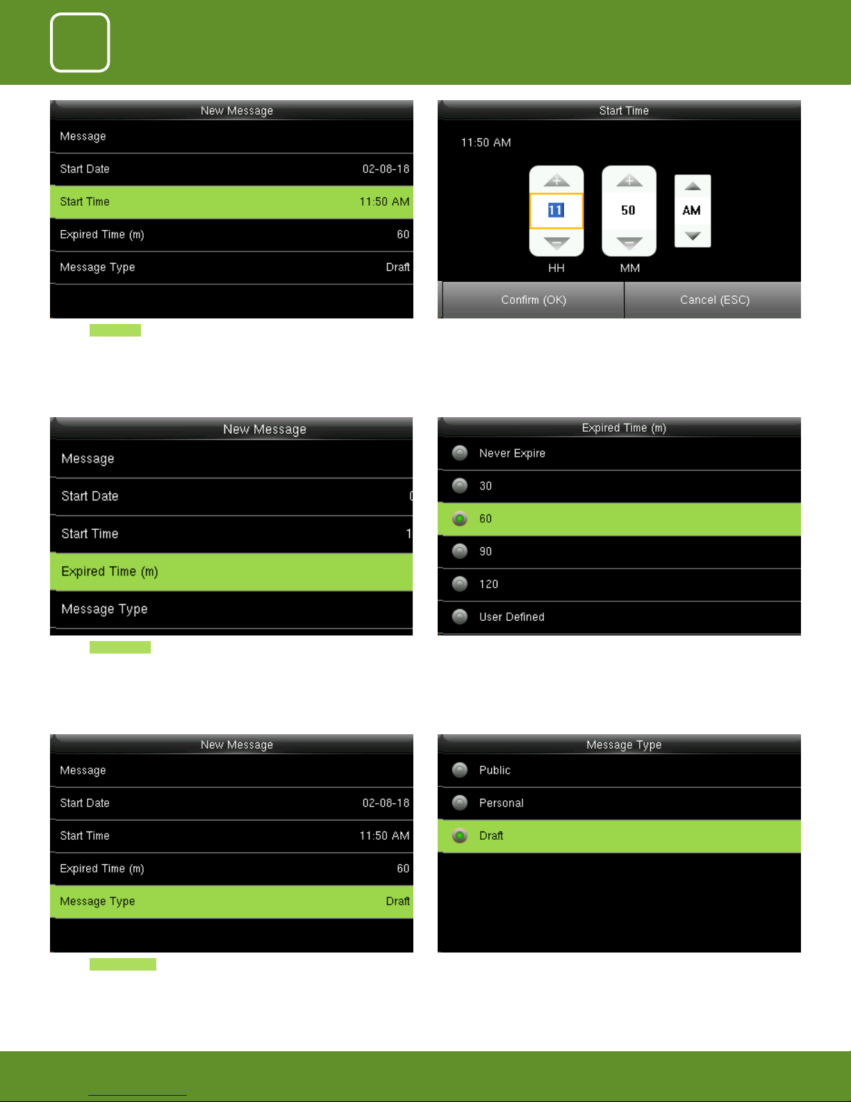
Here you can edit the date you wish the message to be displayed.Click on Start Date .
Page 70
3
4
5
6
7
8
9
10
COMMUNICATION
DATA MANAGEMENT
ACCESS CONTROL
ATTENDANCE SEARCH
USB MANAGER
SHORT MESSAGE
SYSTEM
PERSONALIZE
Click on Start Time .
Click on Expired Time .
Here you can edit the “Start Time” to what time you want the message to be
displayed.
Here you can choose the time you want the message to be expired from the
screen.
The “Expired Time” ranges in minutes.
70
70
70
70
70
70
70
70
From the menu above you can select the “Message Type” you wish to display.Click on Message Type .
Page 71
3
4
5
6
7
8
9
10
COMMUNICATION
DATA MANAGEMENT
ACCESS CONTROL
ATTENDANCE SEARCH
USB MANAGER
SHORT MESSAGE
SYSTEM
PERSONALIZE
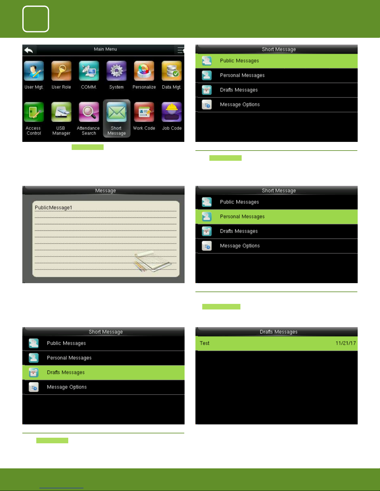
Go to Menu and select Short Message .
The message will be displayed on the screen as above. 10.3 PERSONAL MESSAGES
10.2 PUBLIC MESSAGES
Select Public Message .
Here also if you want to view any Personal Message click
on Personal Message
10.4 DRAFT MESSAGES
Select Draft Messages .
The draft messages will be displayed as above.
71
71
71
71
71
71
71
71
Page 72
3
4
5
6
7
8
9
10
COMMUNICATION
DATA MANAGEMENT
ACCESS CONTROL
ATTENDANCE SEARCH
USB MANAGER
SHORT MESSAGE
SYSTEM
PERSONALIZE
10.5 MESSAGE OPTIONS
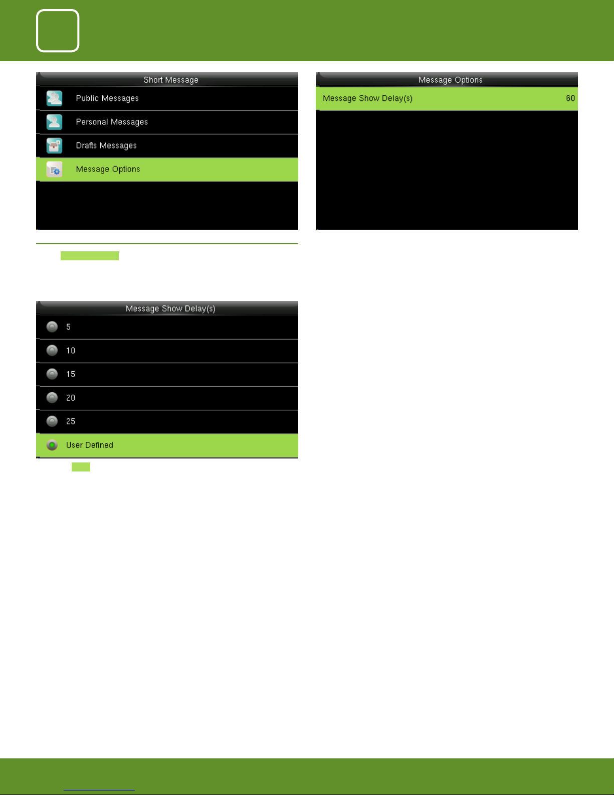
Select Message Options .
Select the Time you want the message to be seen.
The delay time ranges in seconds.
Select “Message Show Delay” to set the delay time for the message to be
seen.
72
72
72
72
72
72
72
72
Page 73

11
WORK CODE
Page 74
11
WORK CODE
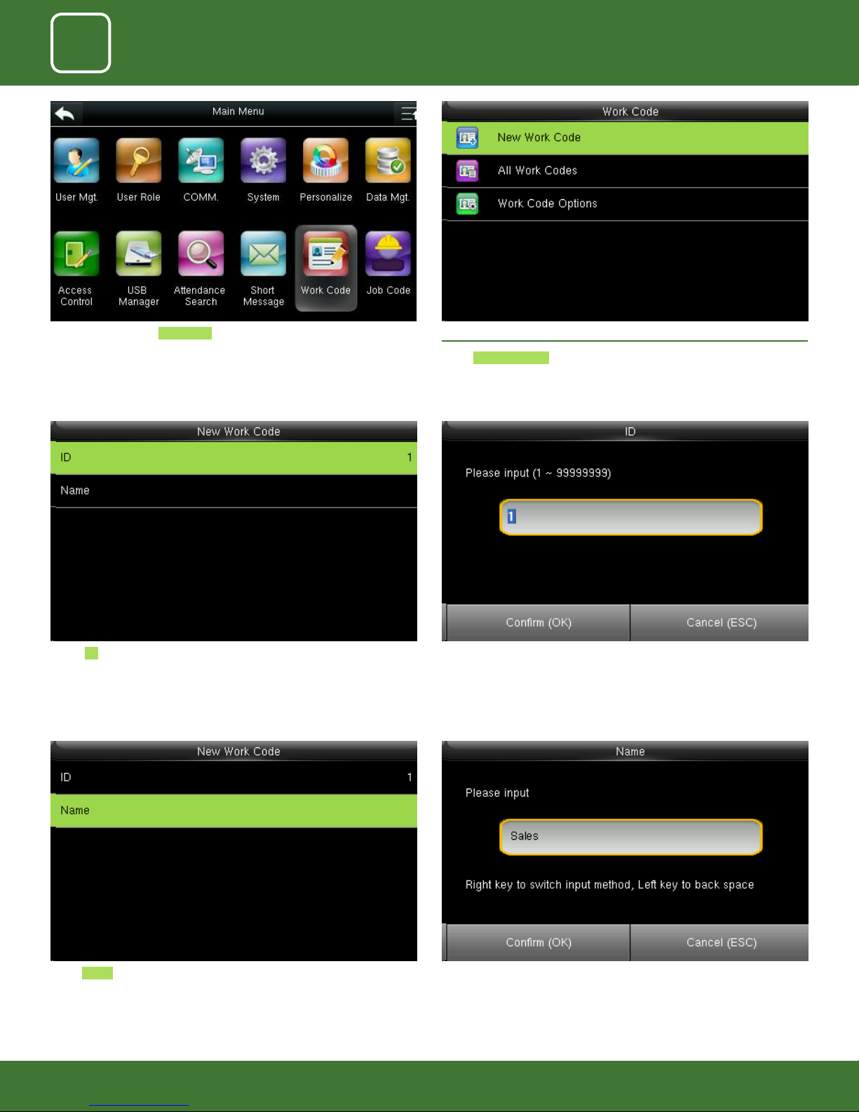
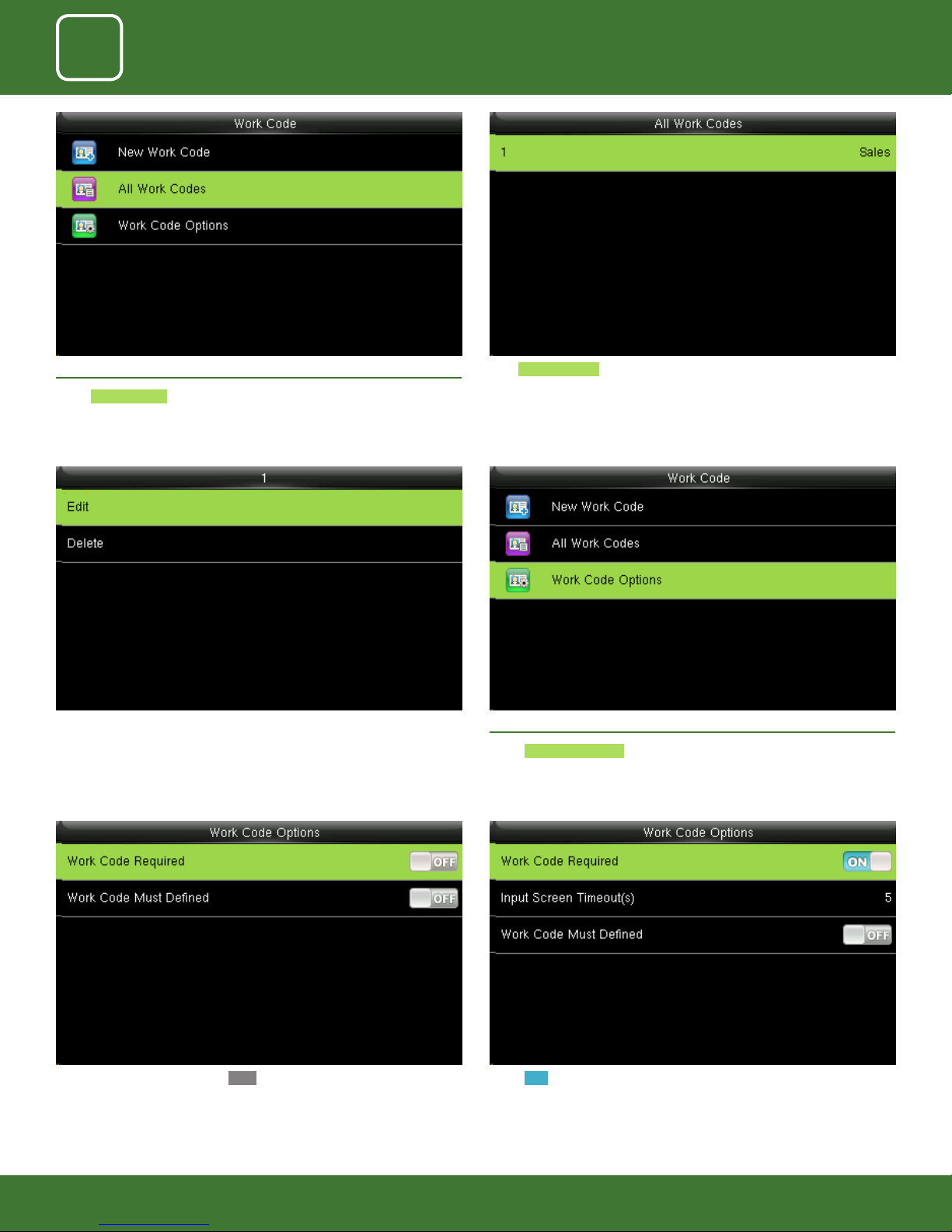
Go to menu and selec Work Code . 11.1 NEW WORK CODE
Select New Work Code .
Select ID . Enter the user ID using keypad for that user.
Select Name . Enter the name of the work code by using the keypad.
74
Page 75
11
WORK CODE
11.2 ALL WORK CODES
Select All work codes .
Sselect the one you want to edit or delete.
In edit you can edit the information and delete will delete the work code for
that ID.
View All work codes.
11.3 SET WORK CODE
Select Work code options .
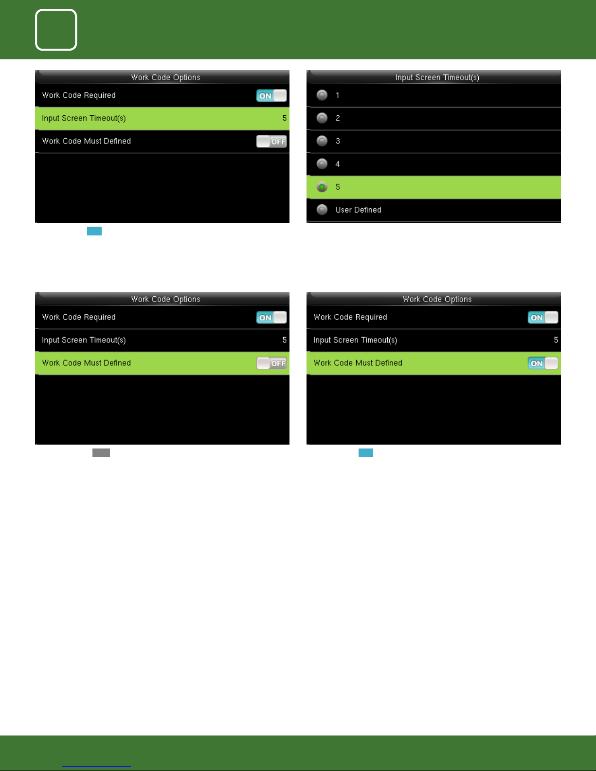
Select ON for workcode required.When the work code required is OFF it will disbale the required work code.
75
Page 76
11
WORK CODE
When you turn ON the workcode required it will ask you to set the timeout
for the input screen.
Click on input screen timeout.
When you select OFF for the function above the work code will not be
dened and will be disabled.
Here you can change the timeout for the input screen from the image
above.
The timeout is in seconds.
When you turn ON the work code will be dened and it will enable that
funtion.
76
Page 77

12
JOB CODE
Page 78
11
12
WORK CODE
JOB CODE
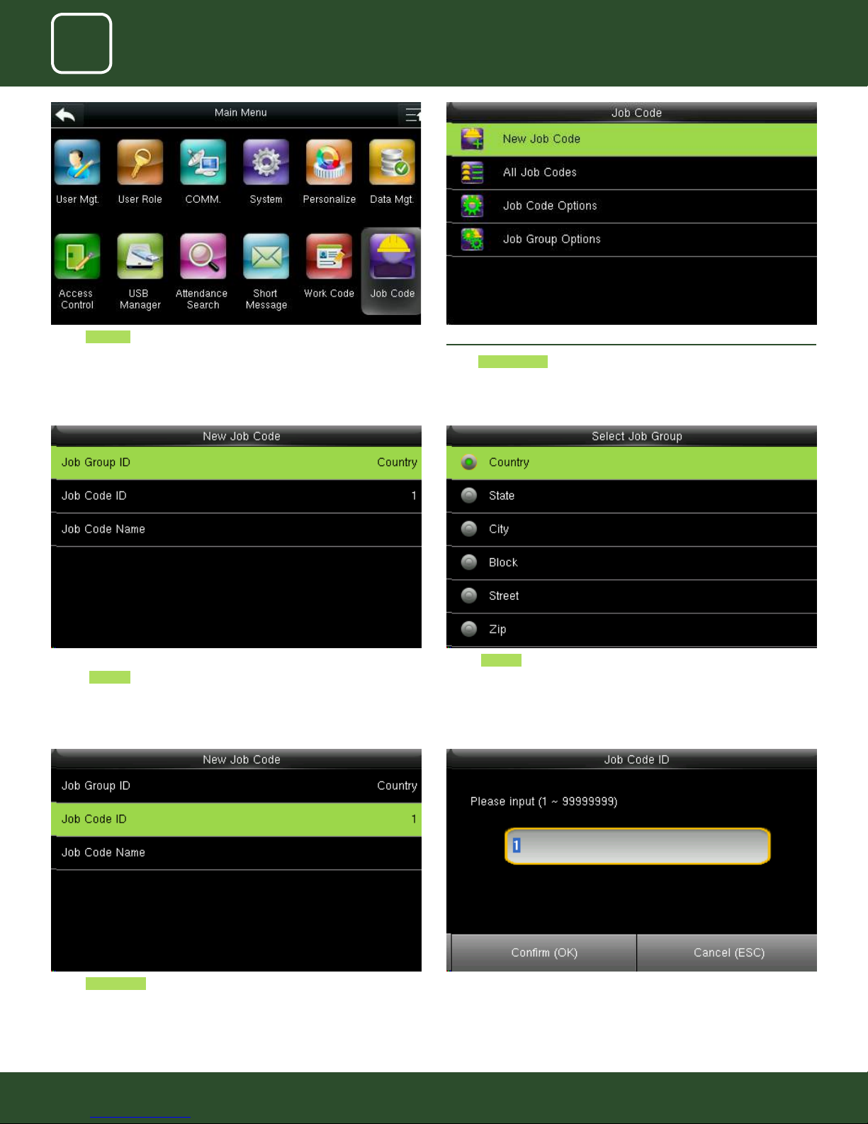
Select Job code icon.
such as Country as shown above.
12.1 NEW JOB CODE
Select New Job Code
Select Country . The job group id will be selected as country.Select Job Group ID and then assign a particular job code from the category
Select Job Code ID Enter Job Code ID or edit Job ID to represent the job code such as NO. 1 as
shown above.
78
78
Page 79
11
12
WORK CODE
JOB CODE
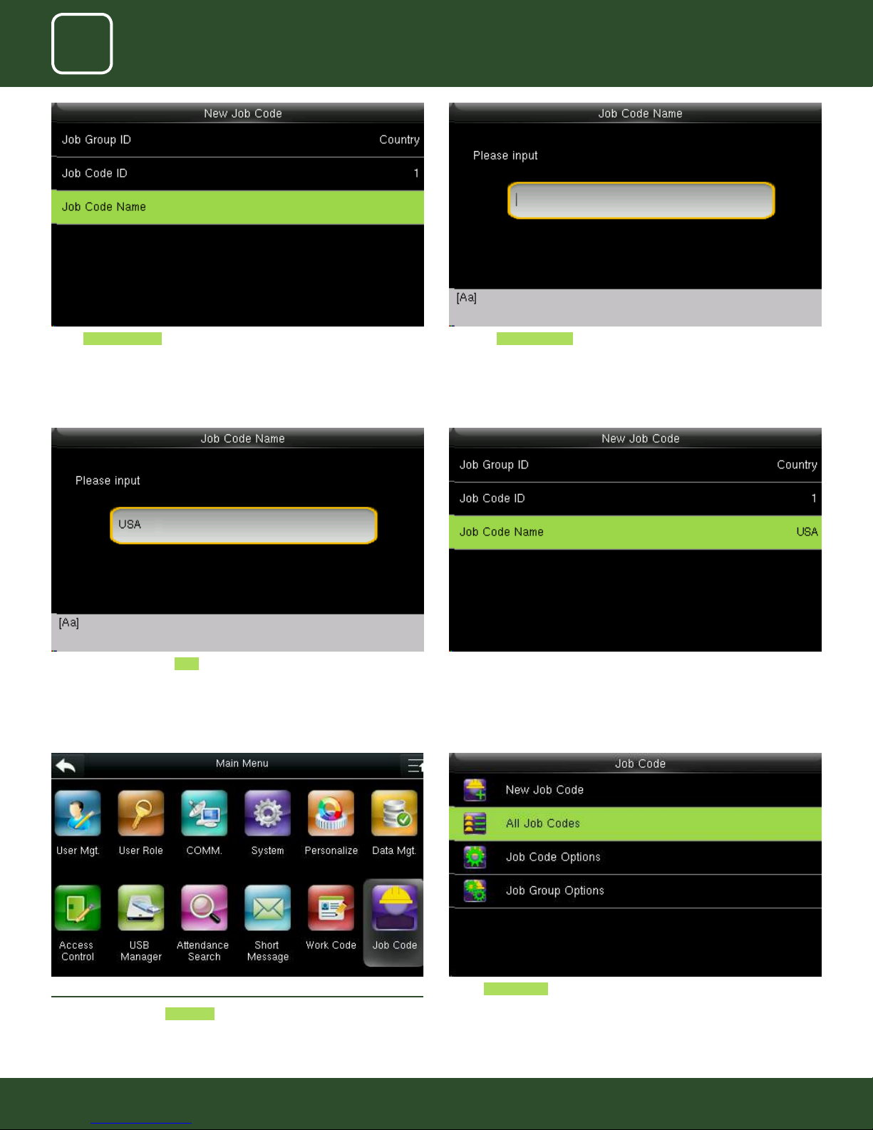
Select Job Code Name . Input the Job Code Name in the box above. With the help of keypad you can
input the name.
Enter the job code name USA as shown above All input information you enter will be displayed on the screen as above.
Press “ESC” button to go back to last menu and it will save all the information
you entered
12.2 ALL JOB CODE
Go to menu and select Job Code
Select All JOB codes .
79
79
Page 80
11
12
WORK CODE
JOB CODE
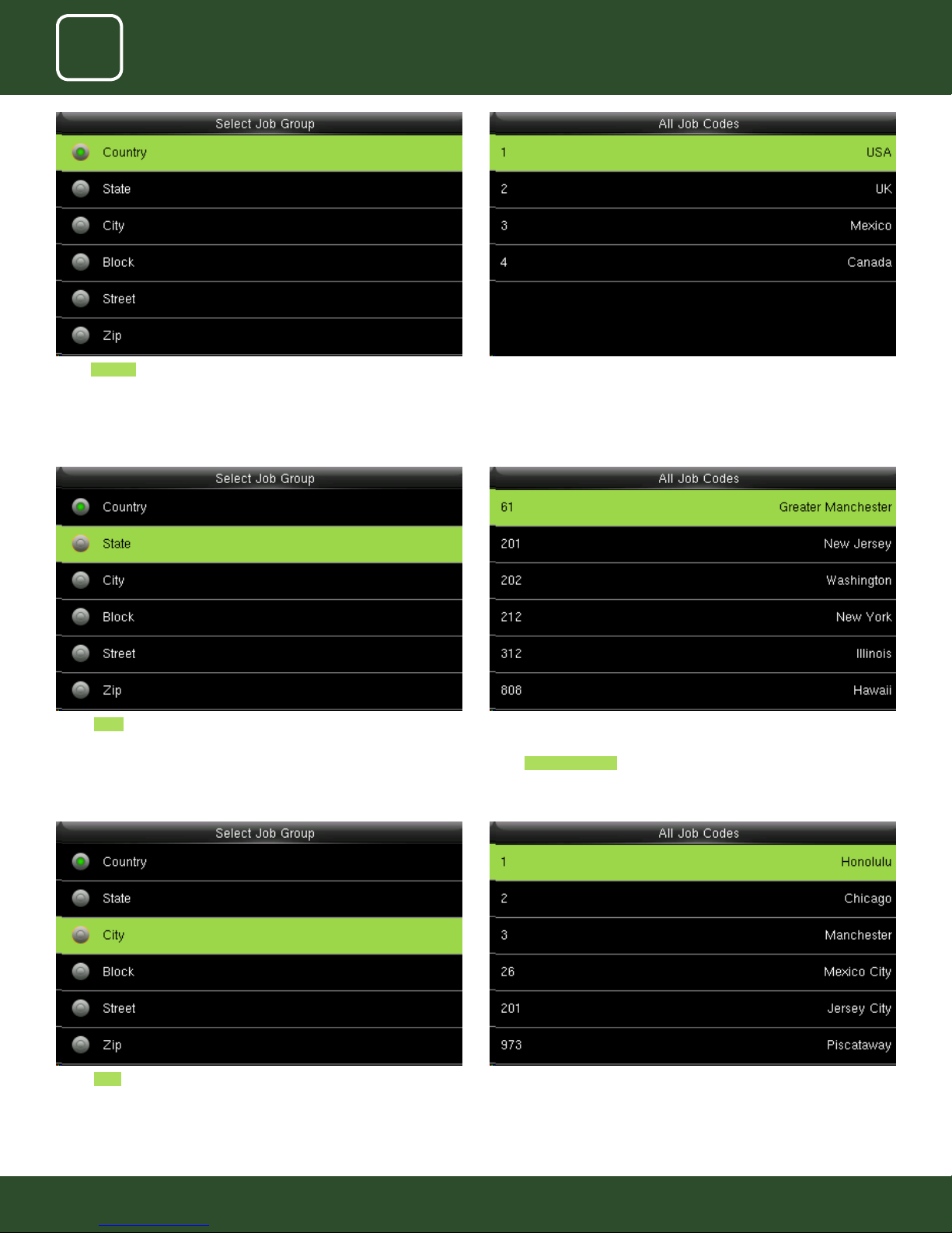
Select Country There is only one job code “USA assigned in to this group” Country 1
Select State After selecting state, it will display all the job codes assign to dierent states
as shown above.
Select Great Manchester as shown above to select the particular state
Select CITY After selecting CITY all the job codes will be displayed according to the city
as shown above and you can select whichever is applicable to you.
80
80
Page 81
11
12
WORK CODE
JOB CODE
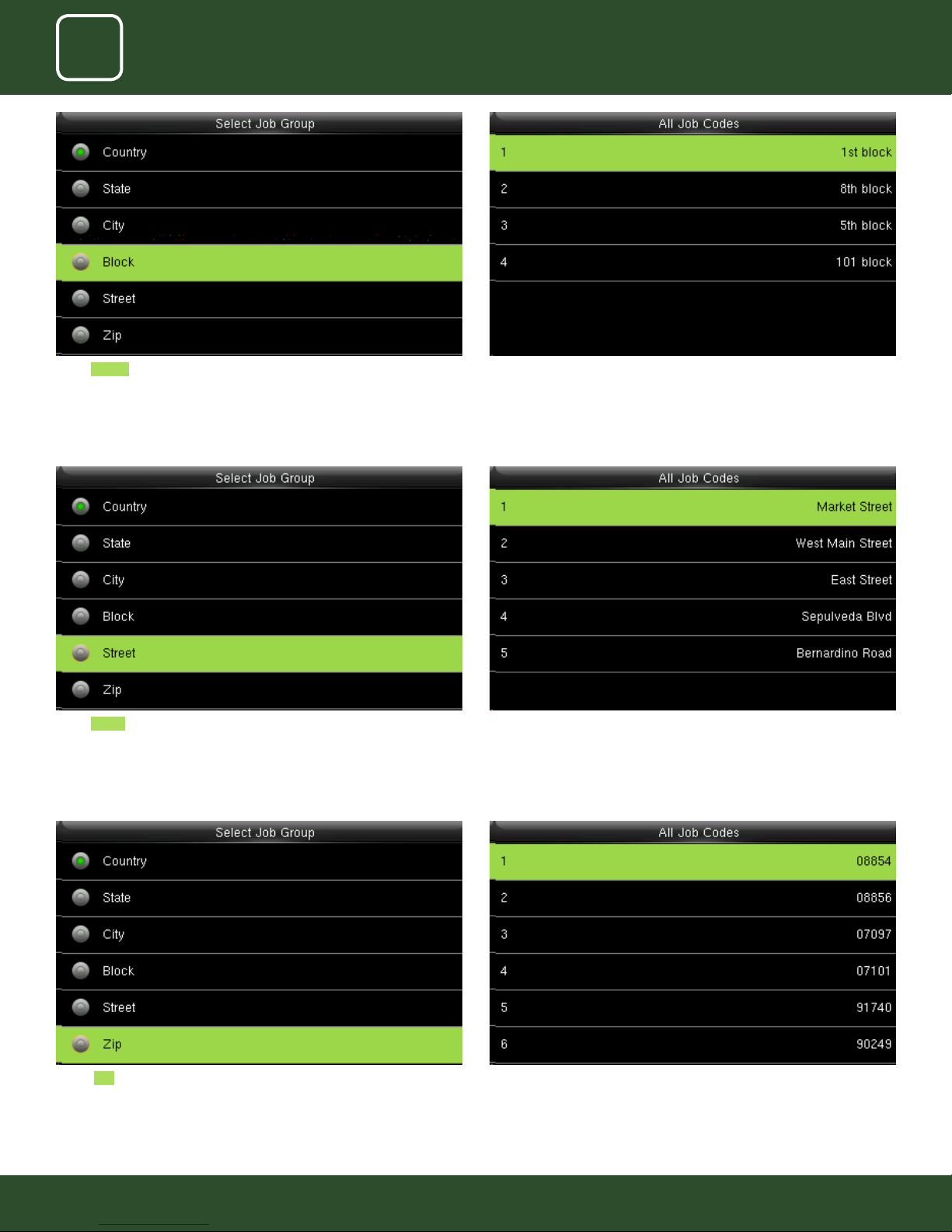
Select BLOCK The dierent block will appear.
Select 1st block as shown above to select the particular block
Select Street The dierent Streets will appear as shown above.
Select Market street as shown above to select the particular street
Select ZIP The dierent ZIP codes will appear as shown above.
Select ZIP Code 08854 as shown above to select the job code for that zip
code.
81
81
Page 82
11
12
WORK CODE
JOB CODE
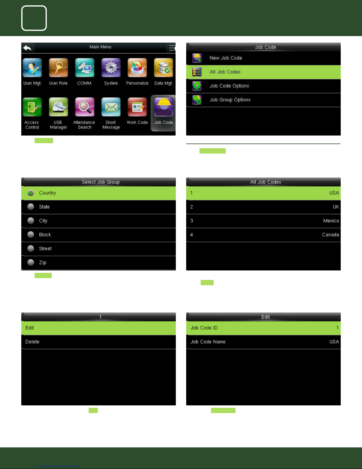
Select Job Code 12.2 ALL JOB CODES
Select All Job codes options.
Select Country The job codes assign to dierent country will be displayed as shown above.
Select 1 USA for the particular job code for that country.
After selecting 1 USA click on the Edit function. Click on the Job code ID if you want to edit the id number from 1 to
dierent number.
82
82
Page 83
11
12
WORK CODE
JOB CODE
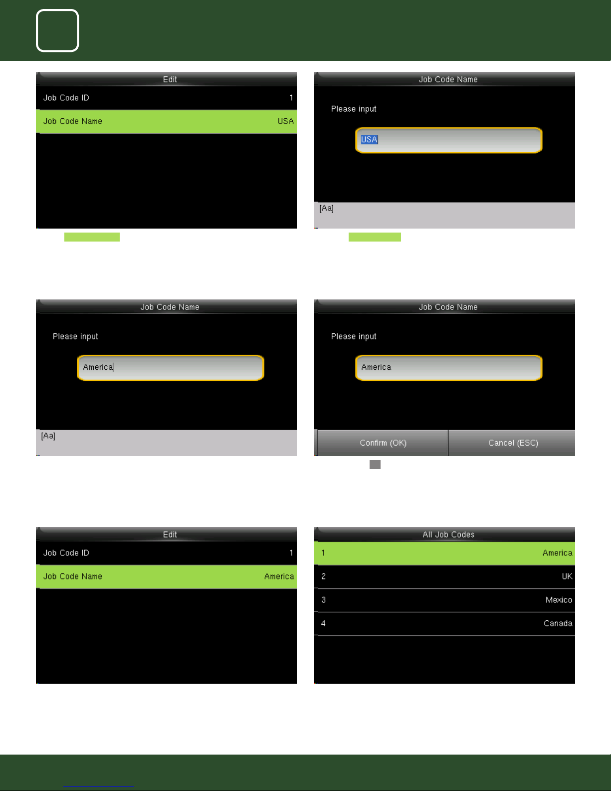
Click on Job Code Name to edit the name for that job code Enter the Job code Name by using the keypad.
Change the name from “USA” to America Click on conrmOK button to select America.
The job code name will change to America as shown above. When you select all job code America will be displayed in job code ID 1 as
shown above.
83
83
Page 84
11
12
WORK CODE
JOB CODE
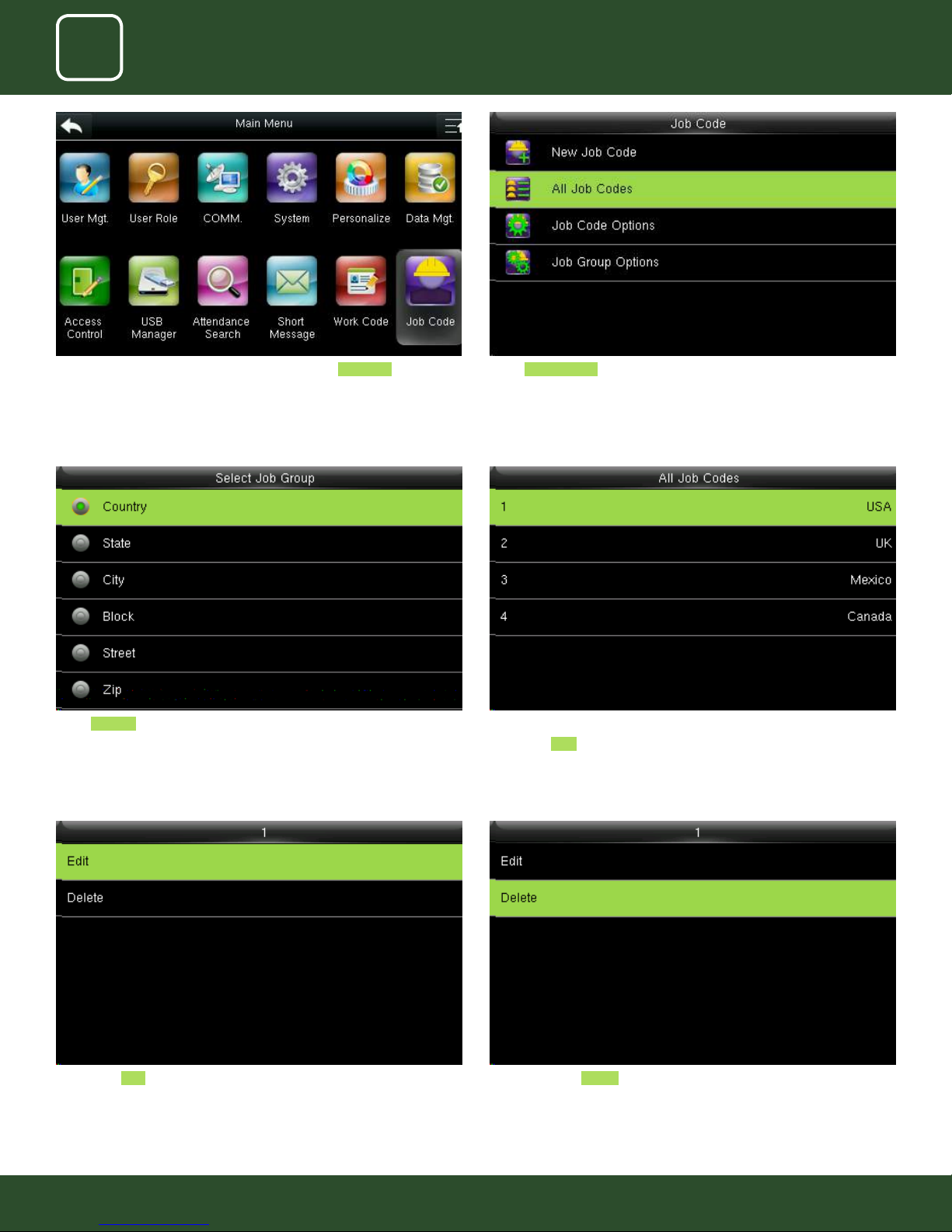
Select All Job Codes To delete the job codes in the particular group select Job Code .
Select Country as shown above
Click on the Edit function to change the name of the group.
Select the job code you wish to delete.
Here select USA .
When you select Delete it will delete the particular group you want to
delete
84
84
Page 85
11
12
WORK CODE
JOB CODE
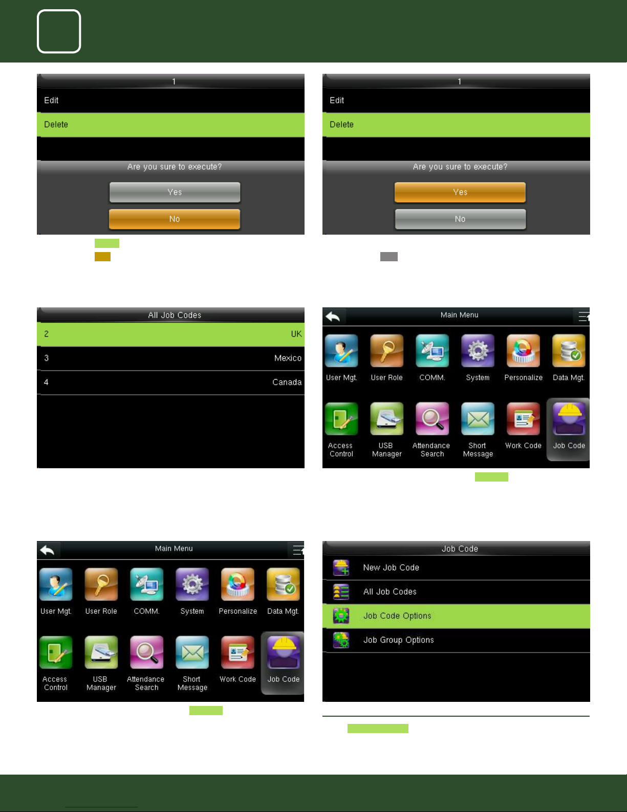
When you press Delete the above screen will be displayed.
When you press NO to execute it will go back to last menu screen and
nothing will be edited or deleted
Group name Country is deleted and the other groups remains as shown
above.
When you press delete the above screen will be displayed.
When you press YES to execute it will execute the function and delete the
particular job group you selected “Country”.
Job Code Options_Menu_Operation select Job Code icon.
Job Code Options_Menu_Operation select Job Code icon. 12.3 JOB CODE OPTIONS
Select Job Code Options .
85
85
Page 86
11
12
WORK CODE
JOB CODE
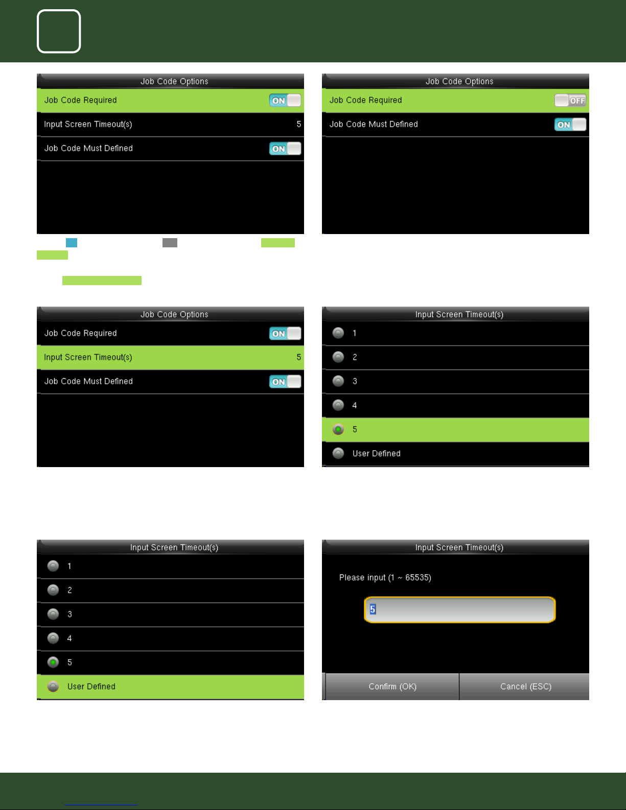
Turning ON options will enable and OFF options will disable the Job Code
Required function “Input Screen Timeout(s)” to set up the time period for
displaying the job code list in seconds.
Switch Job Code Must Dened to force a job code to be selected before
verication.
Select Input Screen Timeout as shown above. Select the time you want the screen to go idle. In this case 5 seconds is
When you turned OFF the job code required function it will disable that
function.
When you turned ON the job code must have dened it will enable the
function and it will show as image above.
selected. when you select 5 seconds the screen will go to idle state if no
registration or activity is performed on the clock.
Select user dened function as shown above to set your own time for input
screen timeout.
After selecting user dened function, the screen above will allow you to
input the time.
86
86
Page 87
11
12
WORK CODE
JOB CODE
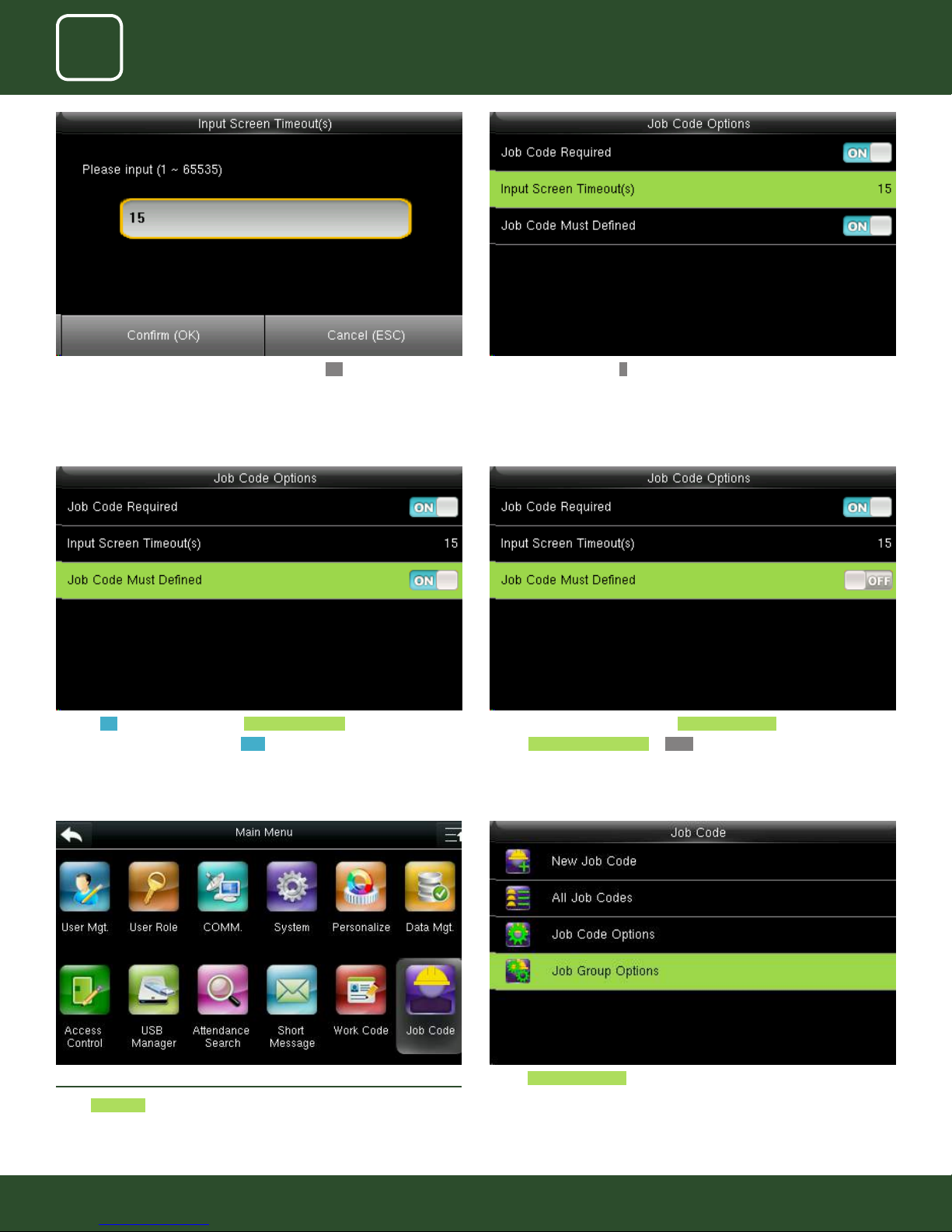
Here we put 15 seconds and then click on conrm OK function to get that
time selected.
Turning ON options will enable the Job Code Required function
Switch “Job Code Must Dened” to ON to force a job code to be selected
before verication
The input screen timeout for job code is selected as 15 seconds as shown
above.
After pressing conrm OK function the image will be displayed as above.
Turning ON options will enable the Job Code Required function
Switch Job Code Must Dened to OFF will not force a job code to be
selected before verication
12.4 JOB GROUP OPTION MENU OPERATION
Select Job code
Select Job Group options .
87
87
Page 88
11
12
WORK CODE
JOB CODE
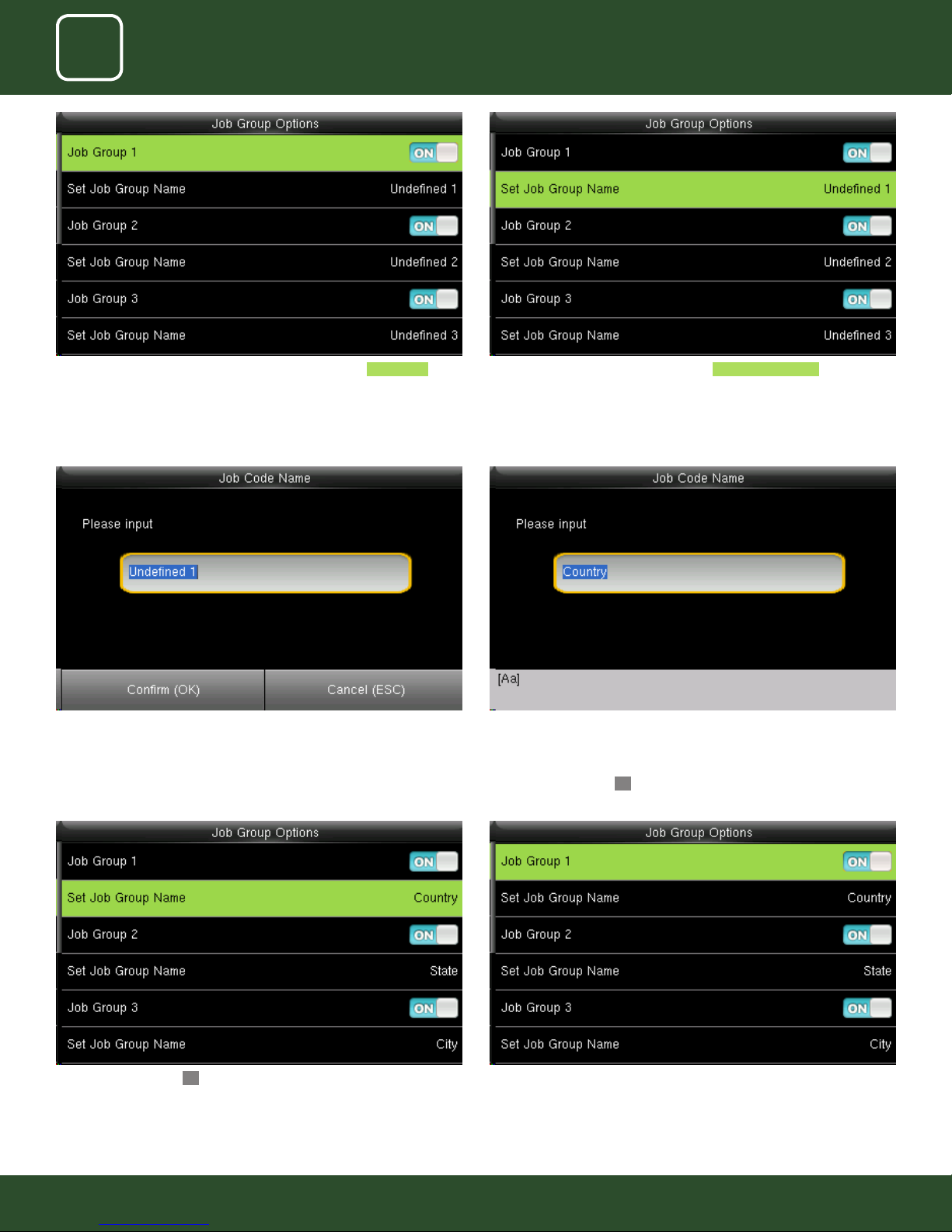
Pressing switch will enable and disable the each individual Job Groups . The name of the group can be edit using Set Job Group Name individually.
To set a Job Group Name click on set job group name as shown above.
This screen will appear when you press the set job group name.
After you press conrm OK button the set group name will change from
undened 1 to Country as shown above.
To change the job group name to country as shown above we need to
press* key to switch the input method and type country using the keypad.
After that press conrmOK button.
Similar way you can put the dierent job group name as shown above.
Group1>> Country, group 2>> State Group3>> City.
88
88
Page 89
11
12
WORK CODE
JOB CODE
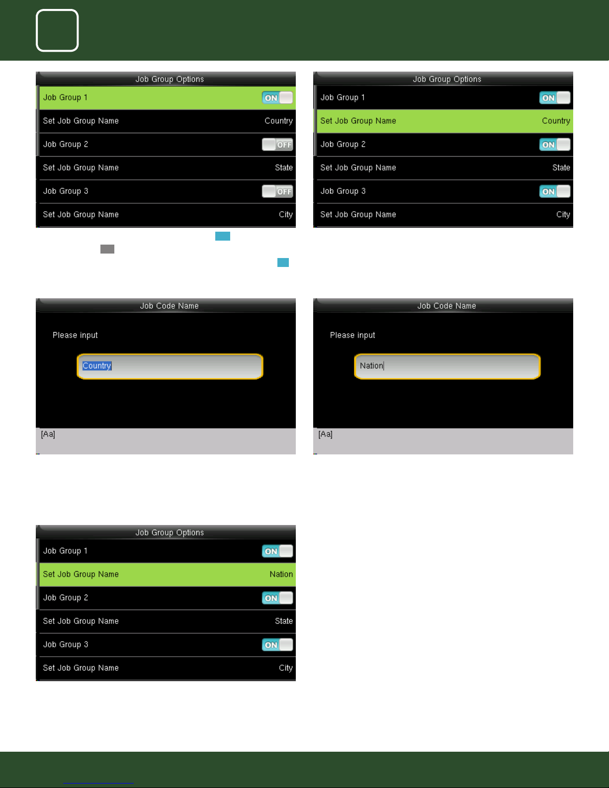
Other groups with OFF functions will be disable.
The job code functions will be active only to the group which is enable ON.
To change the group name select Set Job Group name.Select the job group you want to enable by pressing ON functions.
the clock
The group name will be change to Nation as shown above.
Change the group name as Nation as shown above.Change the current group name country by pressing* key on the keypad of
89
89
Page 90

13
TIP CODE
Page 91
11
12
13
WORK CODE
JOB CODE
TIP CODE
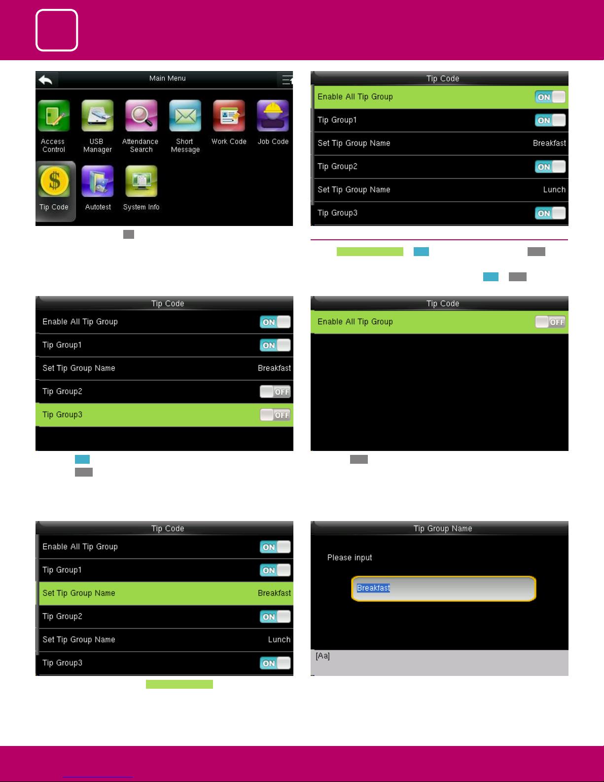
Select Tip Code and press OK.
If you press ON it will enable that tip code function.
If you press OFF it will disable that tip code function
Here Tip group 1 is enabled and Tip Group 2 and 3 are disabled.
13.1 TIP CODE SETTINGS
Switch Enable All Tip Group to ON to enable Tip Code function; OFF to
disable Tip Code function.
The groups can be turned on/o individually using ON or OFF associated
with each tip group
If you press OFF to enable all tip group it will disable all the tip group and
no tip groups will be shown as above.
To set the tip group name select Set Tip Group Name .
When you select the set tip group name the following
image will be displayed and you can edit the name of the group from
breakfast to other name by using the keypad on the screen
91
91
91
Page 92
11
12
13
WORK CODE
JOB CODE
TIP CODE
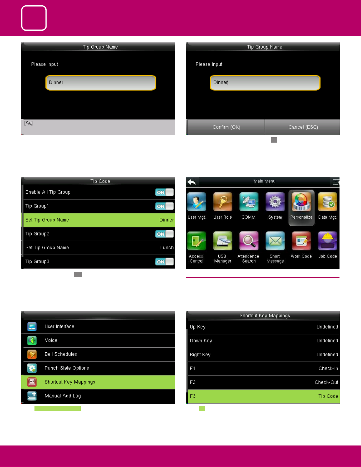
Here the Tip group is being change from breakfast to Dinner with the
keypad on the clock.
Once you hit the Conrm OK button the set tip group name will be
changed to Dinner as shown above.
After you change the name press Conrm OK
13.2 TIP CODE
Select “Personalize”.
Select Shortcut key mappings . Select F3 as tip code.
92
92
92
Page 93
11
12
13
WORK CODE
JOB CODE
TIP CODE
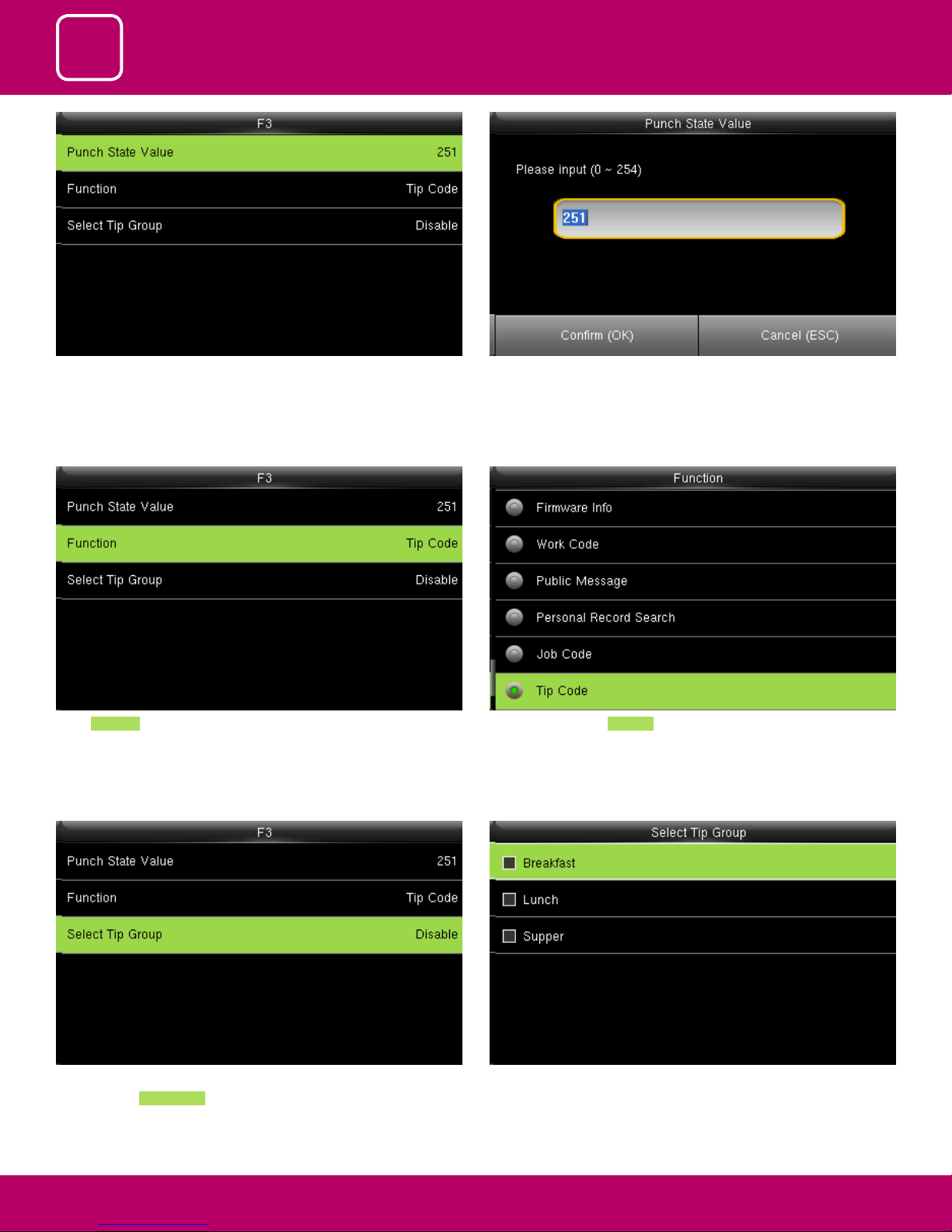
In F3 Select Punch State Value. You can change the punch state value by editing in the input section using
the keypad.
Select Function In function key select TIP code .
Pressing switch will enable and disable the
each individual Job Groups .
If the check mark is not selected on the box no tip group will be selected
and it will be disabled as above
93
93
93
Page 94
11
12
13
WORK CODE
JOB CODE
TIP CODE
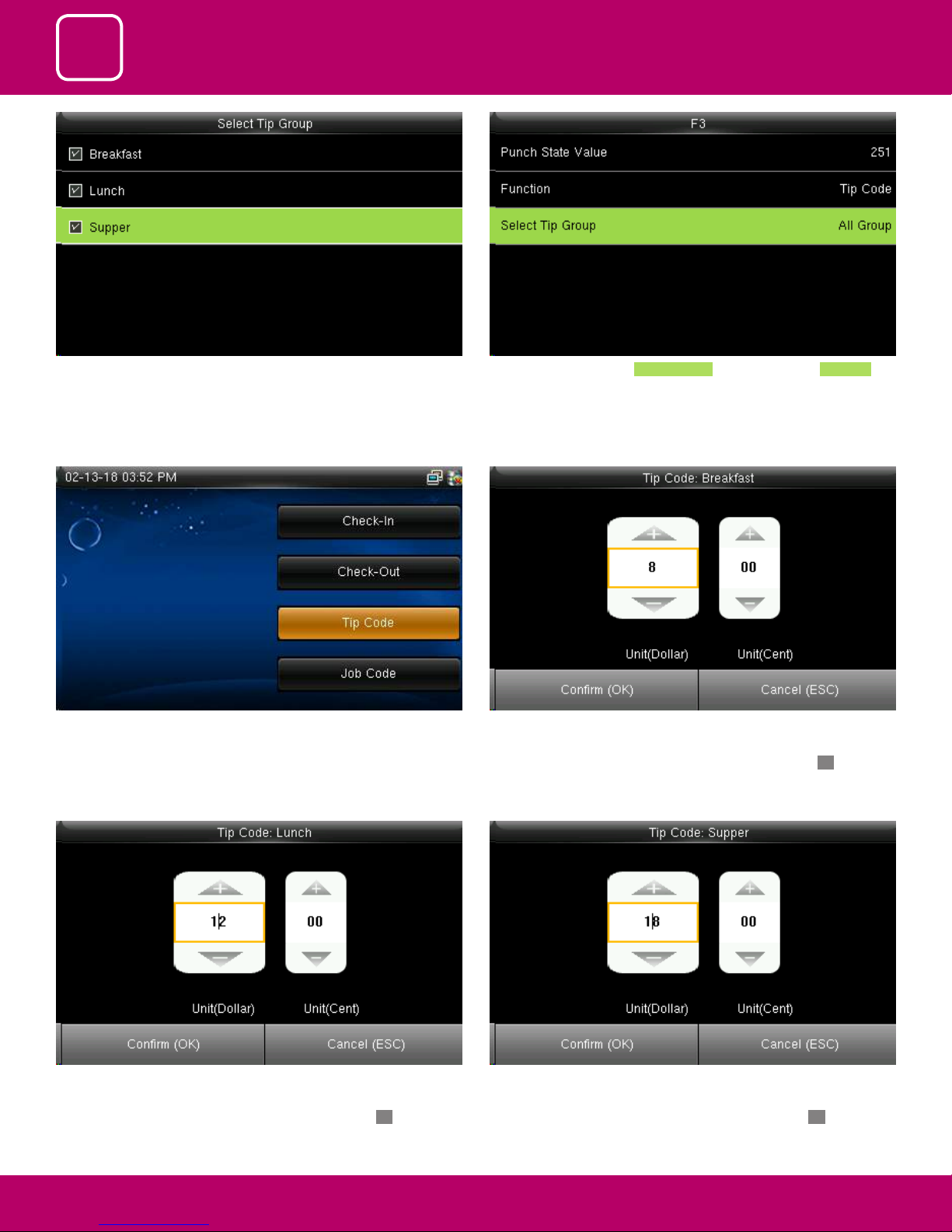
If you check mark all the groups as above all the Tip Group will be enabled. If all three tips are selected, Select Tip Grou will be displayed as All Group .
Select F3 key on the main screen as tip code. You can edit the tip in the amount of dollars by pressing up and down arrow
on the keypad according to group.
Here for breakfast tip is set to 8 dollars and then press conrm OK.
You can edit the tip in the amount of dollars by pressing up and down arrow
on the keypad according to group.
Here for Lunch tip is set to 12 dollars and then press conrm OK.
You can edit the tip in the amount of dollars by pressing up and down arrow
on the keypad according to group.
Here for Supper tip is set to 8 dollars and then press conrm OK.
94
94
94
Page 95
11
12
13
WORK CODE
JOB CODE
TIP CODE
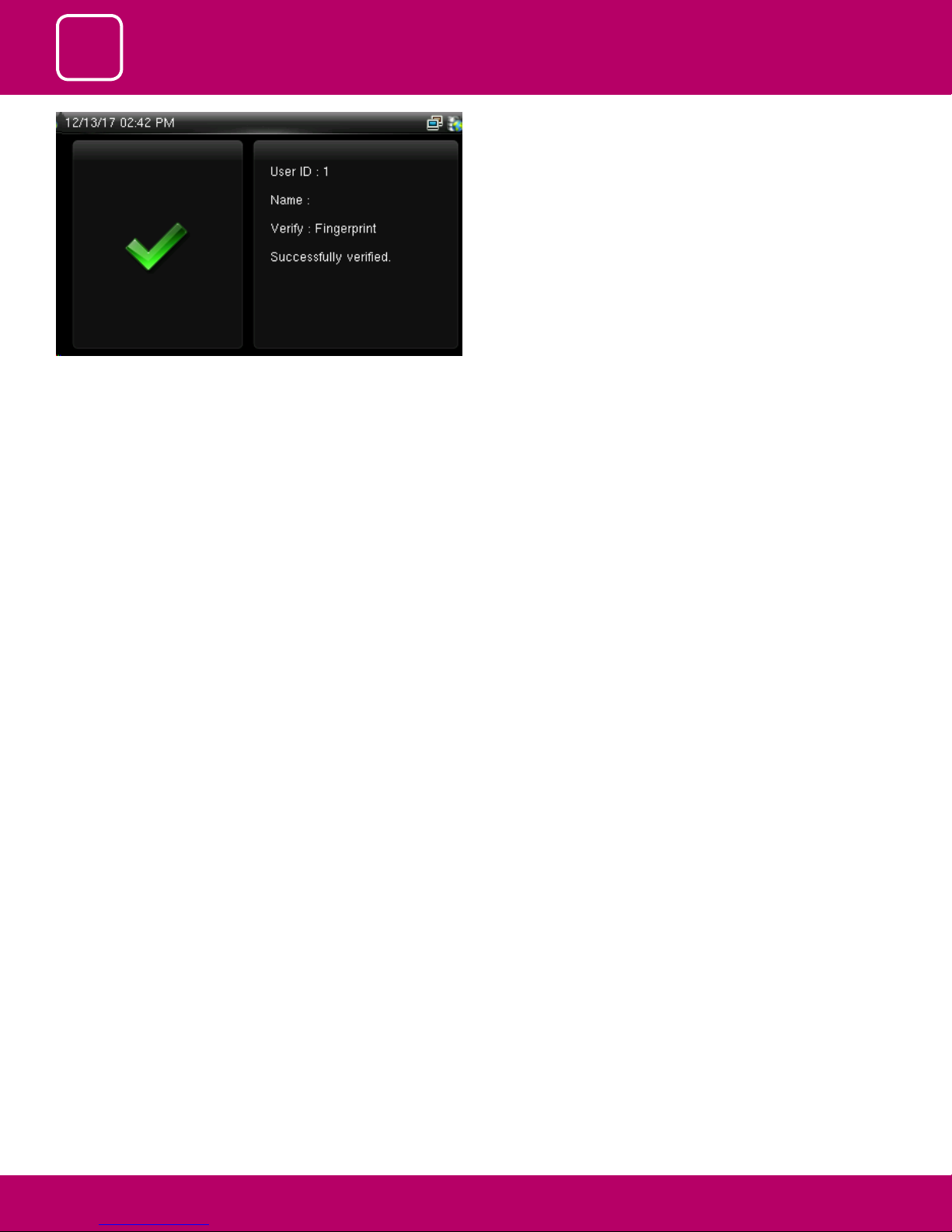
Once all the tip is set according to the group the user from the group can
easily punch in and punch out by their ngerprint and the above image will
displayed if the ngerprint is successfully veried.
95
95
95
Page 96

14
AUTOTEST
Page 97
14
AUTOTEST
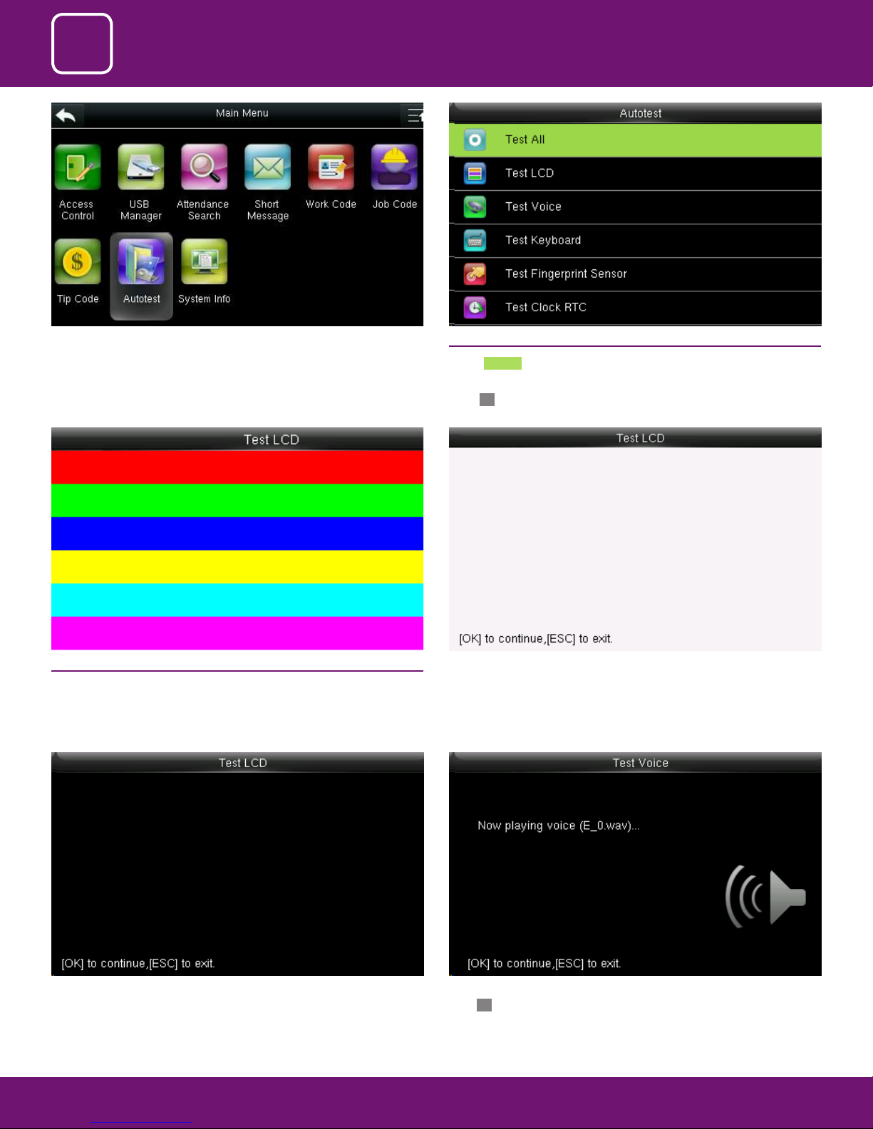
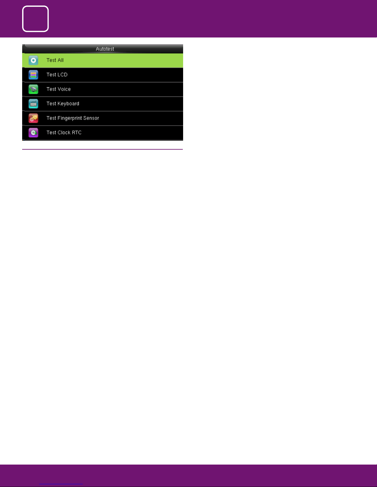
Select “Auto test” . 14.1 ALL TEST
Select Test All .
The terminal automatically tests the LCD, voice, sensor, keyboard and clock,
press OK to continue and press ESC to exit
14.2 TES T LCD
The terminal automatically tests the display eect of the color TFT display
by displaying full color, pure white and pure black and checks whether the
screen displays properly.
The terminal automatically tests the display eect of the color TFT display by
pure black
You can continue the test by touching the screen or exit it by pressing [ESC]
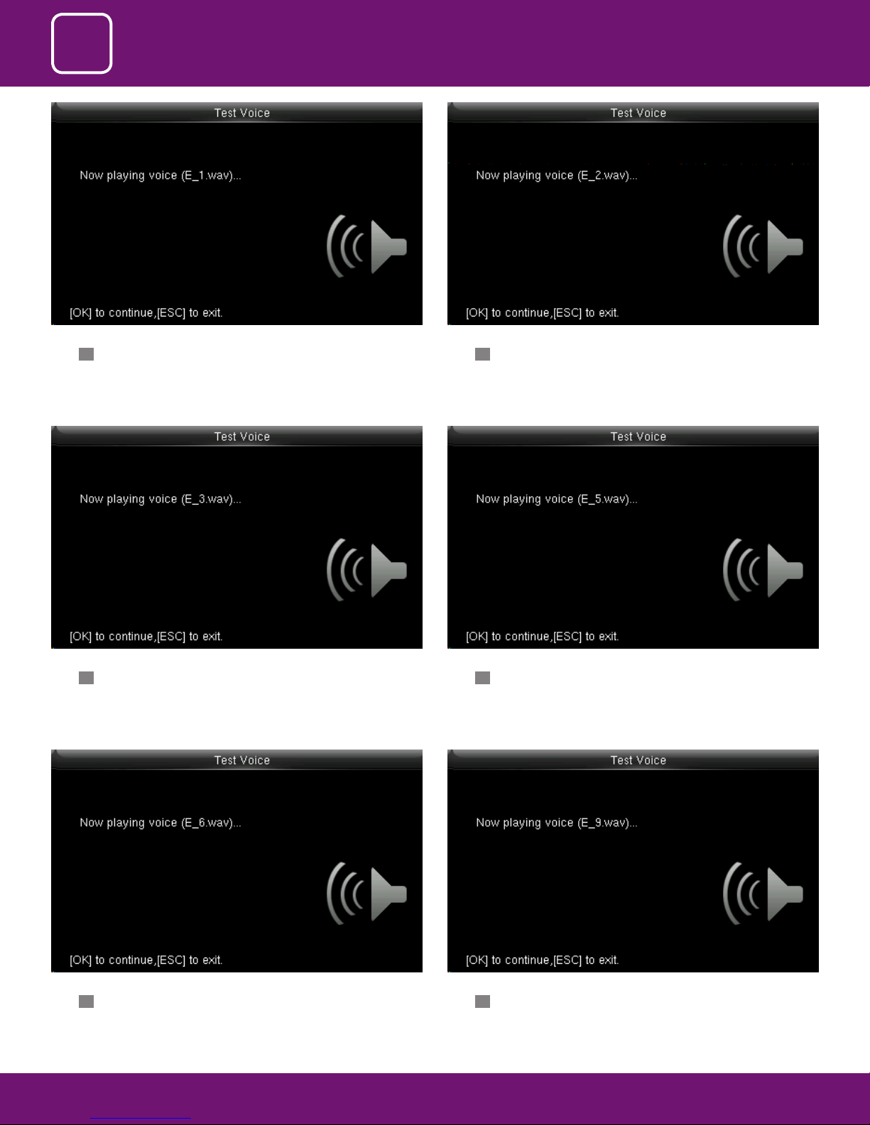
Here you can test the dierent voice wav le. To continue the voice test
press OK and to exit press ESC
97
Page 98
14
AUTOTEST
Here you can test the dierent voice wav le. To continue the voice test
press OK and to exit press ESC
Here you can test the dierent voice wav le. To continue the voice test
press OK and to exit press ESC
Here you can test the dierent voice wav le. To continue the voice test
press OK and to exit press ESC
Here you can test the dierent voice wav le. To continue the voice test
press OK and to exit press ESC
Here you can test the dierent voice wav le. To continue the voice test
press OK and to exit press ESC
Here you can test the dierent voice wav le. To continue the voice test
press OK and to exit press ESC
98
Page 99
14
AUTOTEST
14.3 TEST VOICE
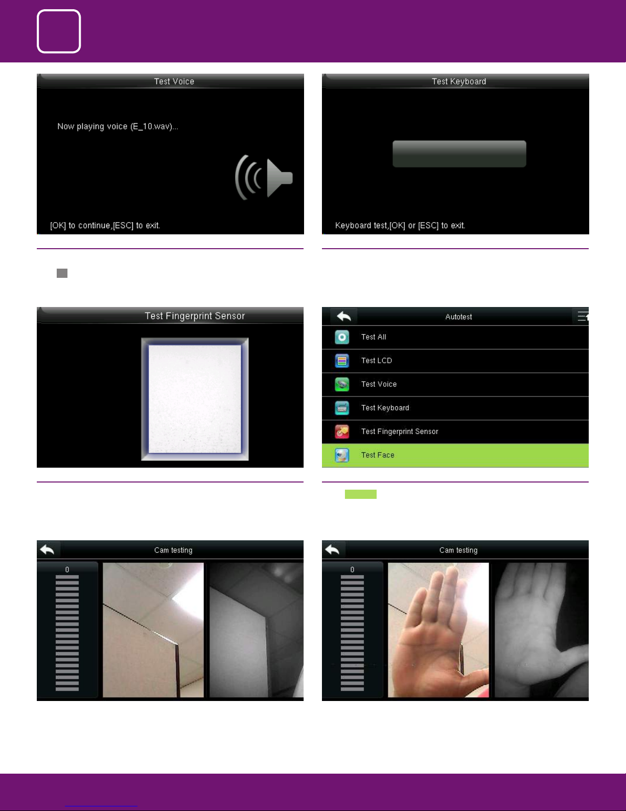
Here you can test the dierent voice wav le. To continue the voice test
press OK and to exit press ESC
14.5 TEST FINGERPRINT SENSOR
The terminal automatically tests whether the ngerprint collector works
properly by checking whether the ngerprint images are clear and acceptable.
When the user places his/her nger in the ngered guide, the collected ngerprint image is displayed on the screen in real-time. Press [ESC] to exit the test
14.4 TEST KEYBOARD
The terminal tests whether every key on the keyboard works normally. Press
any key on the [Keyboard Test] interface to check whether the pressed key
matches the key displayed on screen. The keys are dark-gray before pressed,
and turn blue after pressed. Press [ESC] to exit the test.
14.6 TEST FACE
Select Test Face
When you select to test the face the above image will be displayed where
you can put your face and verify whether the cam is working properly.
Here I took the sample picture to test the camera.
99
Page 100
14
AUTOTEST
14.7 XS TEST CLOCK RTC
Test Clock RTC: The terminal tests whether its clock works properly by
checking the stopwatch of the clock. Touch the screen to start counting, and
touch it again to stop to check whether the counting is accurate. Press [ESC]
to exit the test.
100
 Loading...