

Page 1

1
Technical Service Guide
Compact Dishwasher (6 settings)
MODEL SERIES: WQP6-3705-AU
IMPORTANT SAFETY NOTICE
The information in this service guide is intended for use by individuals possessing adequate backgrounds of
electrical, electronic, and mechanical experience. Any attempt to repair a major appliance may result in personal
injury and property damage. The manufacturer or seller cannot be responsible for the interpretation of this
information, nor can it assume any liability in connection with its use.
WARNING
To avoid personal injury, disconnect power before servicing this product. If electrical power is required for diagnosis
or test purposes, disconnect the power immediately after performing the necessary checks.
RECONNECT ALL GROUNDING DEVICES
If grounding wires, screws, straps, clips, nuts, or washers used to complete a path to ground are removed for
service, they must be returned to their original position and properly fastened.
MIDEA CONSUMER PRODUCTS
TECHNICAL SERVICE GUIDE
COPYRIGHT. 2014
ALL RIGHTS RESERVED. THIS SERVICE GUIDE MAY NOT BE REPRODUCED IN WHOLE OR IN PART, IN ANY FORM, WITHOUT
WRITTEN PERMISSION FROM THE MIDEA DISHWASHER MANUFACTURING COMPANY.
CONTENTS
Introduction ............................................................................................................................................................. 3
Specification ........................................................................................................................................................... 3
Control Panel Features ......................................................................................................................................... 3
Component Locator Views ................................................................................................................................... 4
Dishwasher Components ..................................................................................................................................... 5
Main control board ......................................................................................................................................... 6
Floater assembly ........................................................................................................................................... 7
Heating pump motor assembly .................................................................................................................... 7
Heating pump assembly ............................................................................................................................... 8
Motor assembly .............................................................................................................................................. 9
Drain pump assembly ................................................................................................................................. 10
Check plate ................................................................................................................................................... 11
Inlet valve ...................................................................................................................................................... 11
Control panel ................................................................................................................................................ 12
Page 2

2
Operating board ........................................................................................................................................... 13
Outer Door .................................................................................................................................................... 13
Dispenser ...................................................................................................................................................... 14
Inner Door ..................................................................................................................................................... 14
Shell ............................................................................................................................................................... 15
Door lock assembly ..................................................................................................................................... 16
Air breaker .................................................................................................................................................... 16
Hinge assembly and spring system .......................................................................................................... 17
Tank assembly ............................................................................................................................................. 18
..................................................................................................................................................... 19
Troubleshooting .....................................................................................................................................................21
Test program
Page 3
3
WQP6-3705-AU compact electrical dishwasher with 6 washing cycles offers good washing
performance to satisfy every washing requirement. Its electronic control is easy and convenient to
operate. The rack can hold up to 6 sets of dishes. The size (width * depth * height: 550mm *
500mm * 438mm) can easily fit in any corner of the kitchen, and it’s recommended to locate at
which the water hose connection is accessible.
Rated voltage: 220~240V / 50Hz
Rated power: 1170-1380W
Water pressure: 0.04~1.0MPa
Water temperature:
maximum 60℃
Capacity: 6 settings
Note:
all models have different control panel features and appearances. All detail can be
referred to user manuals of the model.
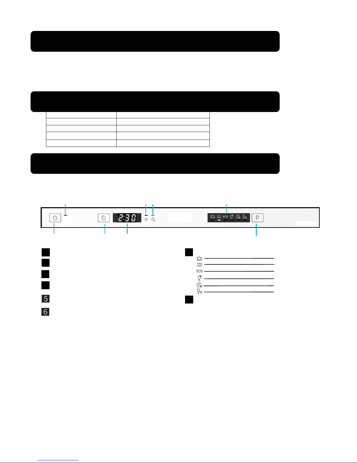
Control Panel Features
Specification
Introduction
1
2
3
4
7
Power Button: To turn on/off the power supply.
Delay Button : To press the button to delay.
Display screen: To show the reminding time
and the state(running state, delay time etc ) .
Rinse Aid Warning Light : To be on when the
rinse aid dispenser needs to be refilled.
.
8
Faucet Light : To be on when the faucet is opened.
1
3
2
4
5
6
8
7
Power indicator
Program Button : To press the button to choose
the pro gramme.
Program indicator expla ins as belo w:
Intensi ve
Heavy
ECO
Glass
90Min
Rapid
Page 4
4
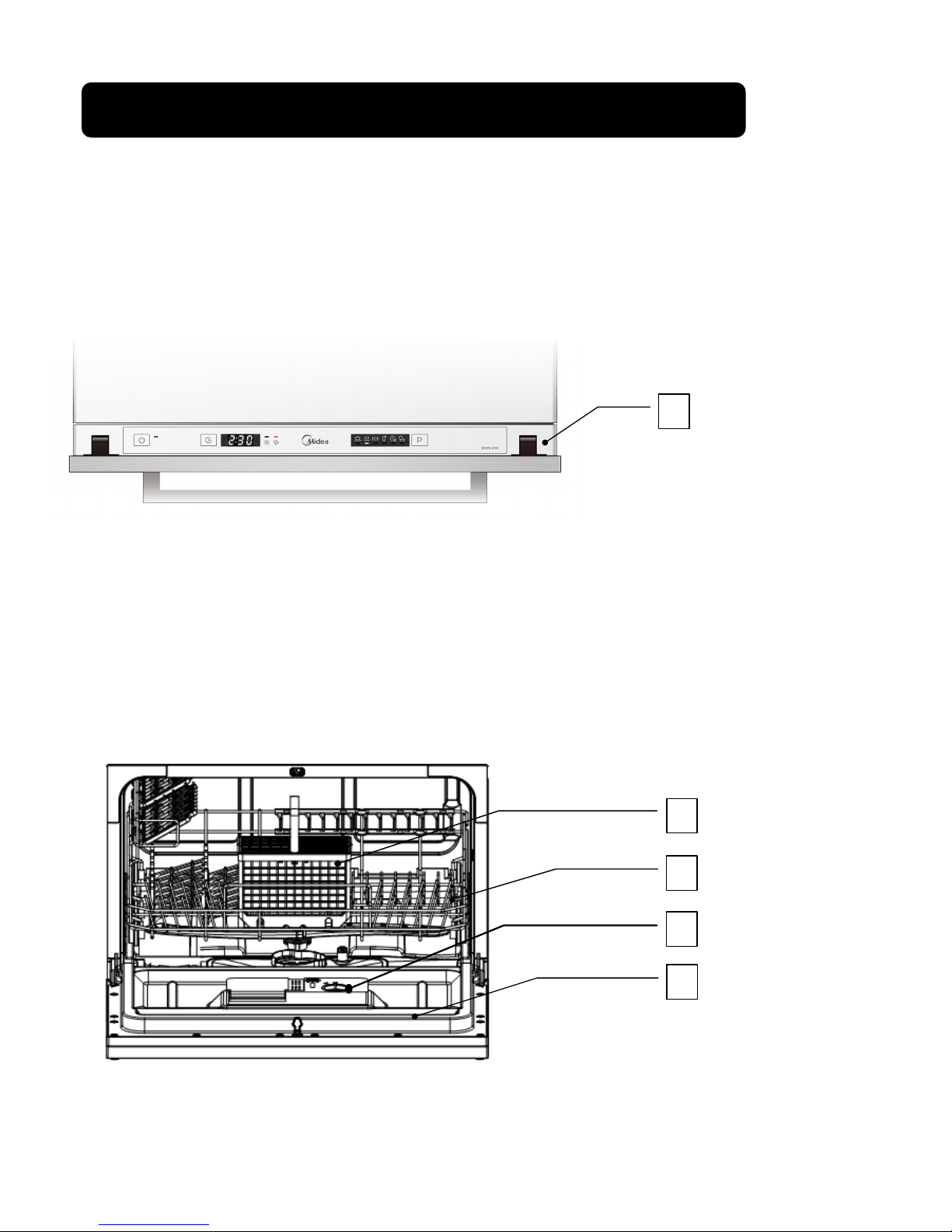
Front View
Part Name:1 – –
outer door
–
Interior View (with basket)
Part Name: 1
–
cutlery basket 2 – basket 3 – dispen
ser
4 – inner d
oor
Component Locator Views
1
2
3
4
1
Page 5
5
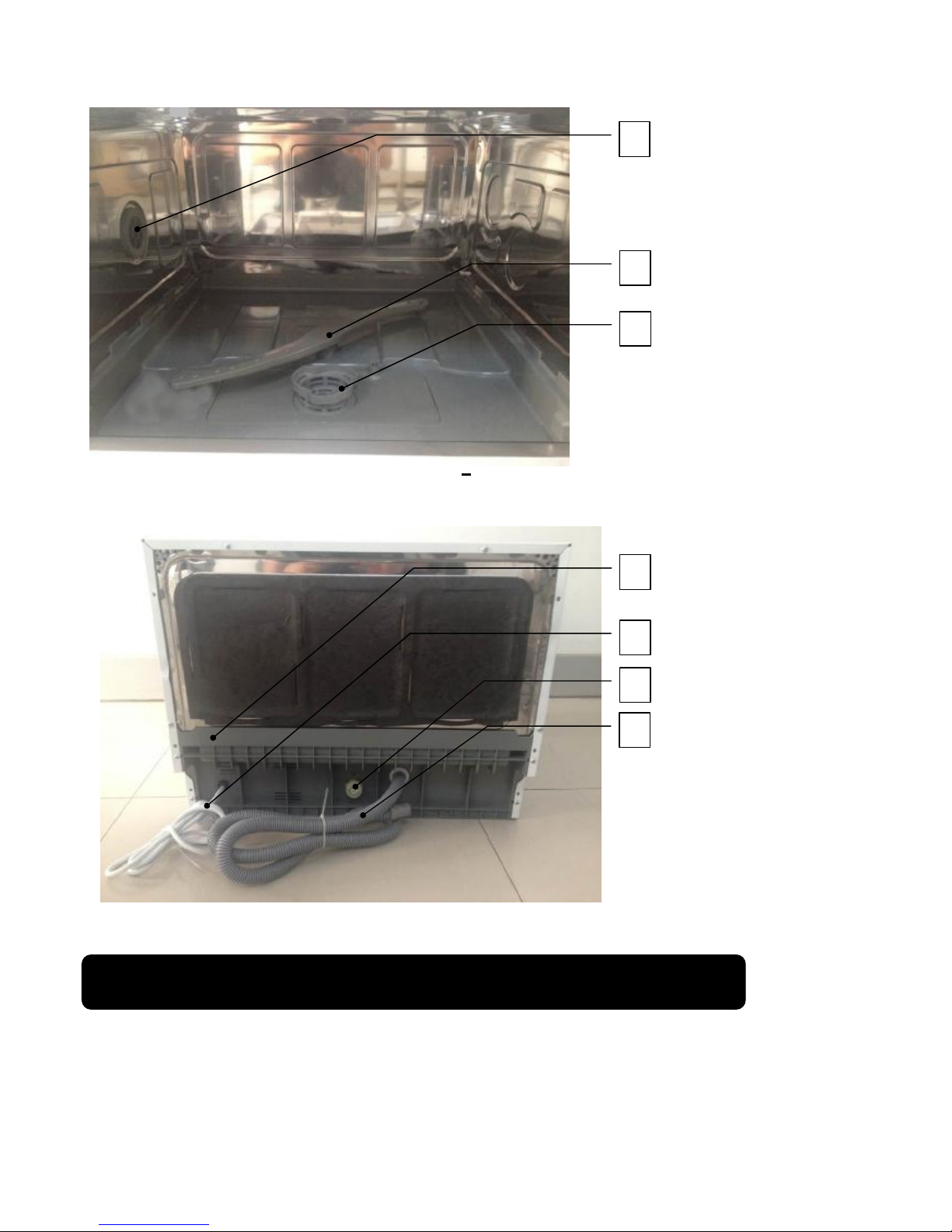
Interior View (With Basket Removed)
Part Name: 1
–
Nut of air breaker
–
2–Sprayer
3
–
Back View
Part Name: 1
–
Bottom board 2 –Power cord 3 –Inlet hose connecter
4 – Outer drain hose
Note: Throughout this manual, features and appearance may vary from your model.
WARNING: Always turn off the electric power supply before servicing any electrical component,
making ohmmeter checks, or replacing any parts.
Note: All voltage checks should be made with a voltmeter having a full scale range of 250 volts
Dishwasher Components
1
2
1
2
3
4
3
Filter System
Page 6
6
or higher. After service is completed, be sure all safety grounding circuits are complete,
all electrical connections are secure, and all access panels are in place.
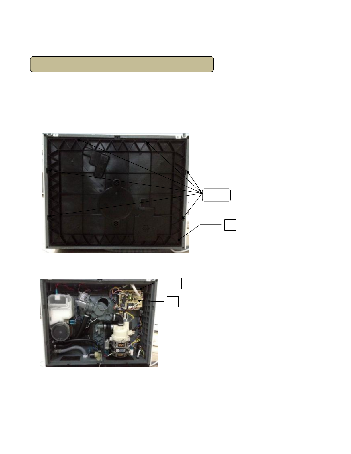
The main control board controls all electrical elements in the dishwasher machine. It located in
the protecting box in the bottom of dishwasher machine. And it easy is replaced when it cannot
work.
Removal and Replacement
1. Disconnect power supply.
2. Take off cutlery basket, basket and filter system.
3. Turn the dishwasher machine. And unfix all snaps for fixing cover of bottom board
.
Part Name: 1
–
cover of bottom board
4. Pull out all housings and terminals (including some locking terminals), then unfix all snaps
for fixing main control board.
Part name: 1 – protecting box 2 – main control board
Note: mark all housings and terminals’ positions and colors before pulling out them.
Note: some terminals are locking terminals.
5. Reverse the above procedure to install. And check out all connectors connects well.
Main control board
1
1
2
snap
s
Page 7
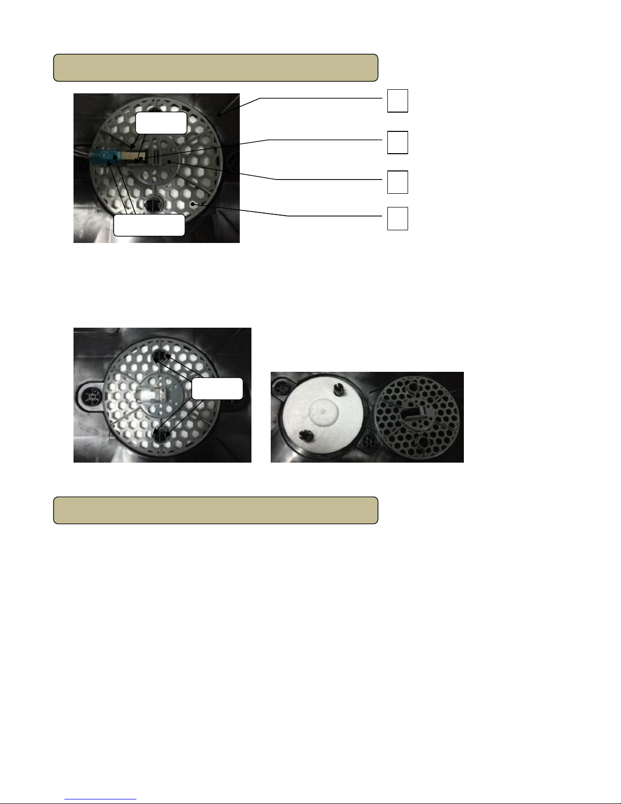
7
Part Name: 1
–
cover of bottom board 2 – microswitch
3 – floater holder 4 – floater
Removal and Replacement
1. Remove cover of bottom board. (see main control board removal and replacement)
2. Pull out all terminals of microswitch.
3. Unfit snaps fixing microswitch to floater holder.
4. Unfit snaps fixing floater holder to cover of bottom board.
5. Reverse the above procedure to install. And check out all connectors connected well.
Floater assembly
Heating pump motor assembly
2
1
3
4
Terminlals
Sn
aps
Sn
aps
Page 8
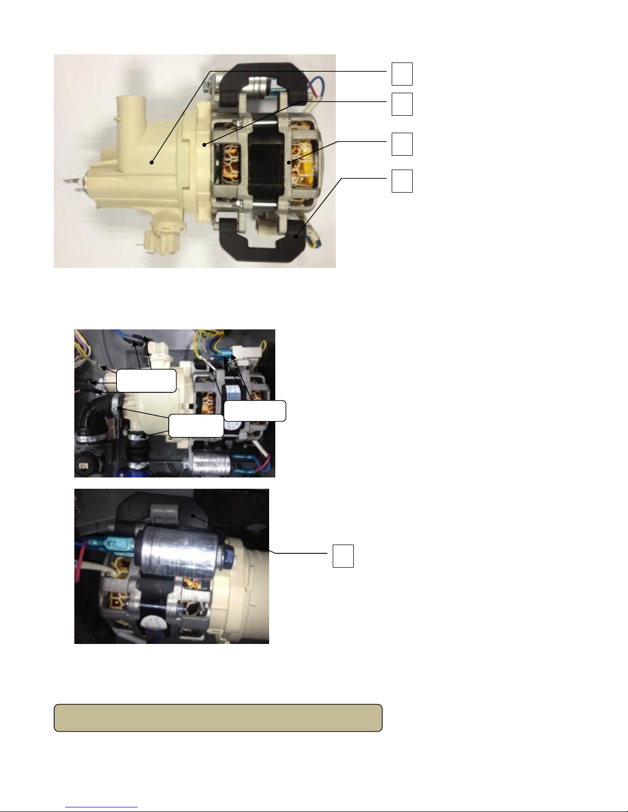
8
Part Name: 1
–
heating pump assembly 2 – lower pump cover
3 – motor assembly 4 – motor hunger
Removal and Replacement
1. Remove cover of bottom board. (see main control board removal and replacement)
2. Pull out all terminals of heating pump motor assembly.
Part Name: 1 – motor hunger
3. Remove clamps fixing heating pump motor assembly to sump of bottom board.
4. Unfit motor hungers fixing heating pump motor assembly to bottom board.
5. Reverse the above procedure to install. And check out all connectors connected well.
Heating pump assembly
2
1
3
4
Clamps
Terminals
Terminals
1
Page 9

9
Part Name: 1
–
upper pump cover 2 – heating element
3 – pressure switch assembly
Removal and Replacement
1. Take out heating pump motor assembly from the dishwasher machine. (see main heating
pump motor assembly removal and replacement)
2. Unfit snap of heating pump assembly, and contrarotate heating pump assembly.
3. Reverse the above procedure to install. And check out all connectors connected well.
Motor assembly
2
1
3
Snap
Page 10

10
Part Name: 1
–
motor hunger 2 – impeller assembly 3 – pump seal ring
4 – lower pump 5 – motor assembly
Removal and Replacement
1. Take out heating pump motor assembly from the dishwasher machine. (see main heating
pump motor assembly removal and replacement)
2. Disassemble heating pump motor assembly. (see heating pump assembly removal and
replacement)
3. Take out two motor hungers, and remove screws for fixing impeller assembly and lower
pump to motor assembly.
4. Reverse the above procedure to install. And check out all connectors connected well.
Removal and Replacement
1. Remove cover of bottom board. (see main control board removal and
replacement)
Drain pump assembly
2
1
3
5
Screws
4
Page 11

11
2. Pull out all terminals of drain pump assembly.
3. Unfit snap of drain pump assembly, and contrarotate drain pump assembly to take it out.
4. Reverse the above procedure to install. And check out all connectors connected well.
Removal and replacement
1. Remove cover of bottom board. (see main control board removal and
replacement)
2. Remove clamp fixing inner drain hose to bottom board, and pull it out .
Part Name: 1 – inner drain hose 2 –check plate assembly
3. Pull out check plate from check plate holder, and replace a new check plate.
4. Reverse the above procedure to install. And check out all connectors connects well.
Removal and Replacement
1. Remove cover of bottom board. (see main control board removal and replacement)
2. Pull out all terminals of inlet valve.
Check plate
Inlet valve
Terminals
Snap
1
2
Page 12

12
3. Remove clamp for fixing connecting hose to inlet valve, and contrarotate inlet valve to take it
out.
4. Reverse the above procedure to install. And check out all connectors connected well.
The outer door covers the door to the dishwasher and protects the detergent dispenser.
Removal and Installation
1. Open the door of dishwasher. And remove all screws for fixing control panel.
2. Remove screw, and unfix all snaps for fixing the pcb cover,then take out operating board.
Part Name: 1
–
Control panel 2
–
operating board
–
3. Reverse the above procedure to install. And check out all connectors connected well.
Control Panel
Clamps
Terminals
Screws
1
2
Page 13

13
Removal and Replacement
1. Disconnect power supply.
2. Remove all screws for fixing control panel. (see control panel removal and installation)
3. Put out all housings for connecting operating board.
4. Remove screw and unfix all snaps for fixing the operating board. (see control panel
removal and installation)
5. Reverse the above procedure to install. And check out all connectors connected well.
The outer door covers the door to the dishwasher and protects the detergent dispenser.
Removal and Installation
1. Open the door of dishwasher. And remove all screws for fixing outer door.
2. Reverse the above procedure to install. And check out all connectors connected well.
Front View (with outer door assembly removed)
Part Name: 1
–
stream resistant cotton 2 – dispen
ser
3 – sound absorbing
cotton 4 –door hinge (left) 5 –door hinge(right) 6 – rod for door
hinges 7 – kick board
Operating board
Outer Door
5
1
2
3
4
6
7
Screws
Page 14

14
The dispenser automatically dispenses both the detergent and the rinse agent at the appropriate
times. The dispenser is activated twice during a wash cycle.
The first time, the dispenser is activated, the lever slides up the right-hand path of the
connecting rod. This action moves the cover catch and releases the detergent cover. When
deactivated, the lever resets to rest under the notch in the center of the connecting rod. When
activated for the second time in a cycle, the lever lifts the connecting rod by the notch, lifting
the rinse dispenser plunger and releasing the rinse agent. When deactivated, the lever returns
to its original starting position. The magnetic sensor is connected to rinse aid warning light at
control panel by wires. When the indicator lights up, it should add more rinse aid.
Part Name: 1
–
cover catch 2 – detergent power compartment
3 – cover 4 –sight glass 5 – rinse agent cap
6 – detergent tablet compartment
Part Name: 1
–
electromagnetic valve 2 – lever
3 – plunger 4 – connecting rod
5 – magnetic sensor
Removal and Replacement
1. Remove outer door assembly. (see outer door removal and installation)
2. Pull out all terminals of dispenser. Then remove all screws for fixing dispenser.
Part Name: 1 – dispenser brackets 2 – dispenser
3. Reverse the above procedure to install. And check out all connectors connected well.
Caution: Inner door of edges are sharp.
Inner Door
Dispenser
5
1
2
3
4
6
4
1
2
3
5
terminals
2
1
Screws
Page 15

15
Removal and Replacement
1. Remove outer door assembly. (see outer door removal and installation)
2. Remove control panel .(see control panel removal and installation)
3. Remove dispenser. (see dispenser removal and replacement)
4. Remove all screws for fixing inner door to right hinge assembly and left hinge assembly.
5. Remove dispenser. (see dispenser removal and replacement)
6. Reverse the above procedure to install. And check out all connectors connected well.
Removal and Installation
1. Remove all screws for fixing shell with tank and bottom board assembly in the rear of
dishwasher machine.
2. Push the shell from front to back. And take it away from the machine.
3. Reverse the above procedure to install. And check out all connectors connects well.
Top View (with shell removed)
Shell
Screws
Screws
Page 16

16
Part Name: 1
–
door switch assembly 2 – absorber 3 – 4 –backboard
Removal and Replacement
1. Disconnect power supply.
2. Remove shell. (see shell removal and installation)
3. Unfit snap of door lock assembly, and push it out.
4. Pull out all terminals of microswitch fixed on the door lock assembly.
5. Reverse the above procedure to install. And check out all connectors connected well.
Removal and Replacement
1. Remove shell. (see shell removal and installation)
2. Take out absorbing cotton, upper basket and lower basket.
3. Contrarotate nut of air breaker and take out it.
4. Pull out terminal of air breaker, and unfit snaps of air breaker fixing on softener.
Door Lock Assembly
A
ir breaker
1
2
3
4
Snap
Locking terminals
clamps
Page 17

17
5. Turn the dishwasher machine, remove the cover of bottom board. (see main control board
removal and installation)
6. Remove all clamps for fixing connecting hoses to air breaker.
7. Reverse the above procedure to install. And check out all connectors connected well.
Part Name: 1 – spring holder 2 – spring 3 – friction strip 4 – absorbing cotton
5 – hinge assembly
Removal and Replacement
1. Remove shell. (see shell removal and installation)
2. Take out absorbing cotton.
3. Take off spring holder from the slot of bottom board.
Caution: This operation must be more carefully, it is easy to be injured by the friction strip.
Hinge assembly and Spring system
snap
1
2
3
4
5
Page 18

18
4. Remove all screws for fixing hinge assembly to bottom board.
5. Reverse the above procedure to install. And check out all connectors connected well.
Removal and Installation
1. Remove shell. (see shell removal and installation)
2. Take out absorbing cotton.
3. Remove air breaker. (see air breaker removal and replacement)
4. Remove all screws for fixing tank assembly to bottom board.
5. Reverse the above procedure to install. And check out all connectors connected well.
Tank assembly
Screws
Screws
Page 19

Test Program
During test program running you can press Program button to jump into
next step except inlet valve step
,
().
How to activate Test Program
In order to check the operation of components of appliance and find out the malfunction, we
designed this program for technician.
How to ac tivate
Test Program
With door opened,
Program+ Power
Start Test
Program
Close the door
Jump into next
step
Program
E1
E3
E4
E6
E7
Test Program Operation
19
To activate test program, with the door opened and within 60s after power on,
hold down the Program button and press the POWER button until the
machine enter into Test Program.
Then close the door to start the Test Program.
E1
E3
E4
E6
E7
Page 20

Test Program
No. Process
0 Intialization
1 Inlet Valve
2
Washing Pump
and Heating
Element
3 Washing Pump
and Dispenser
4
static
5DrainPump
6 finish
Procedure of Test Program
(for models controlling w ater filling by flowmeter)
Display on
the screen
05 or
Turbidity
value
03
Description
8:88 Power on, stand by
Open inlet valve and feeds with 1.9L wate
04/Temper-
ature value
Run washing pump and 10s later run heating
element until the water temperature reaches 57℃. Then the
machine will pause.
Press Program button to jump into the next step.
F* Buzz one sound, stop, and stand by.
washing pump for 10s, dispenser will
act for 45s in this step.
static 30s.02
01 Drain for 30s.
Running fan closed after 10 seconds
20
Page 21

21
Troubleshooting
E1 Water filling exceed pre-set time
If the inlet valve has been opened for 4 minutes but the water quantity hasn’t reached the
desired value(measure by pluses), E1 would occur.
When E1 occurs, the drain pump will run until flowmeter keep motionless for 2 minutes
and all the other components will be stopped immediately.At the same time, the buzzer
will alarm for 30 seconds and error 1 will be shown.
How does the appliance react when error code occurred
E3 Heating exceed pre-set time
If the heating element has been working for 60 minutes but the water temperature
detected by NTC hasn’t reached desired value. E3 would occur.
When E3 occurs, the drain pump will run until flowmeter keep motionless for 2 minutes.
and all the other components will be stopped immediately.At the same time, the buzzer
will alarm for 30 seconds and the error 3 will be shown.
E4 Overflow
In test program, once open-circuit failure of thermistor is detected by controller, the E6
would occur. When E6 occurs, the drain pump will run until flowmeter keep motionless for 2
minutes. and all the other components will be stopped immediately.
At the same time, the buzzer will alarm for 30 seconds and error 6 will be shown.
E6 Open-circuit failure of thermistor
At any time, if overflow micro-switch act and keep for longer than 2 seconds, the E4 would
occur. When E4 occurs, the drain pump will run until flowmeter keep motionless for 2
minutes . and all the other components will be stopped immediately.
At the same time, the buzzer will alarm for 30 seconds and error 4 will be shown.
Note: Priority level of E4 is the highest. E4 operation is valid after other error operations
have done. When E4 operation has done, all the others are invalid.
Page 22

22
’
In test program, once short-circuit failure of thermistor is detected by controller, the E7
would occur. When E7 occurs, the drain pump will run until flowmeter keep motionless for 2
minutes . and all the other components will be stopped immediately. At
the same time, the buzzer will alarm for 30 seconds and error 7 will be shown.
E7 Short-circuit failure of thermistor
Page 23

E1 Tree
If the problem has not been solved through all
the inspection mentioned above, maybe the
PCB has a malfunction. So, replace PCB and
test again.
E1 code
Longer inlet time
Make a check of Tap
No water
Not open
Open it to solve the
problem
Opened
Check whether the Inlet
Valve circuit is correct or
not. (mentioned in section
4)
solve the problem
Not
Correct
Make a check of the
Hydraulic pressure.
(0.04-1.0MPa is ok)
Little water
Give advice to
consumer
Lower
Make a check of
Drain Hose
OK
Is there any
water in the Tub?
Reconnect the wire of
Inlet Valve circuit and
check again
OK
Still wrong
Replace the Inlet
Valvetosolve
problem
Make a check of Inlet
Hose
solve the problem
Inlet Hose is blocked or
kinked
OK
Failure Failure
Make a check of inlet
hose of AQUASTOP,
(only for the dishwasher
with AQUASTOP device)
Replace it to solve
the problem
Failure
Hang correctly to
solve the problem
Wrong
Check whether the
Flowmeter circuit is correct
or not. (mentioned in
section 4)
Reconnect the wire of
Flowmeter circuit and
check again
Not
solve the problem
OK
Replace the
Flowmeter to solve
problem
Still wrong
Model with Flowmwter
23
Page 24

E3
Longer heating time
Check water
temperature in the tub
Low
Check whether the
NTC circuit is correct
or not.(mentioned in
section 4)
High
Not
Make a check of over heat
proof heating Micro-switch.
Replace Switch to
solve the problem
Failure
OK
Make a check of Heater.
(mentioned in section 4)
Failure
solve the problem
Reconnect the wire of
Heater circuit and check
again
OK
Still wrong
Replace the Inlet
Valvetosolve
problem
Check whether the
Washing Pump circuit is
correct or not. (mentioned
in section 4)
Reconnect the wire of
Washing Pump circuit
and check again
Not
solve the problem
OK
Replace the
WashingPumpto
solve problem
Still wrong
OK
Reconnect the wire of
NTC circuit and check
again
solve the problem
OK
Replace the NTC to
solve problem
Still wrong
Check whether the filter is
jammed severely or not
Clear or replace filter
to solve the problem
Jammed
OK
E3 Tree
24
Page 25

E4
Overflow
Is there any water on
the bottom board?
Makeacheckof
Flooding Switch
circuit(normally closed)
solve the problem
Reconnect the wire of
Flooding Switch circuit
and check again
OK
Still wrong
Repair or Replace it
to solve problem
No water
Check whether Flooding
Switch is blocked or not
Blocked
Failure
Makeacheckof
Drain Hose
Some
water
Drain Hose is kinked
or blocked
Solve the problem
Failure Failure
OK
Make sure consumer use
the proper detergent and
rinse
Give advice
OK
Improper
Do as follows
Remove the water from the bottom board and make sure there is no water at the bottom board.
Restart the dishwasher with a strong or standard wash program as a leakage could easily repeat at a higher temperature and after a long period
of running time.
Observe the bottom tray every twenty minutes.
If any water appears, you will found out which areas, such as motor, drain pump, sump, softener, and hoses between them, and also clips at the
end of each hose, besides the weld seam at the bottom of the tub.
If hours passed, but no water comes out, you should stop the dishwasher with sufficient water in the inner tub, and observe it again after leaving
it alone for one to two hours.
Check whether the
Flowmeter circuit is correct
or not. (mentioned in
section 4)
Reconnect the wire of
Flowmeter circuit and
check again
Not
solve the problem
OK
Replace the
Flowmeter to solve
problem
Still wrong
Correct
Model with
Flowmeter
E4 Tree
25
Remove the shell
Page 26

E6
Open-circuit failure of
thermistor
Check whether the NTC
circuit is correct or not.
(mentioned in section 4)
Reconnect the wire of
Flowmeter circuit and
check again
Not
solve the problem
OK
Replace the NTC to
solve problem
Still wrong
E7
Short-circuit failure of
thermistor
Check whether the NTC
circuit is correct or not.
(mentioned in section 4)
Reconnect the wire of
Flowmeter circuit and
check again
Not
solve the problem
OK
Replace the NTC to
solve problem
Still wrong
E6-E7 Tree
If the problem has not been solved through all the inspection mentioned above, maybe the
PCB has a malfunction. So, replace PCB and test again.
Caution:
Because the real situation is unpredictable, inspection trees mentioned in this manual are
for reference only.
26
 Loading...