

Page 1

INSTALLATION & OWNER’S MANUAL
Thank you very much for purchasing our product,
Before using your unit, please read this manual carefully and keep it for future reference.
ALL IN ONE Type Air-source Heat Pump Water Heater
Page 2
HOT WATER CAN BE DANGEROUS
Warning – Hot water burns. As a safety precaution, young children should always be supervised around
hot water fixtures.
Heat pump water heaters can store water at temperatures that can cause scalding. Water temperatures
over 50°C can scald and care needs to be taken to ensure that injuries do not occur through incorrect
use of your water heater.
As heat pump water heaters can generate water temperatures in excess of 60°C, regulations require
that a tempering valve be fitted to the heater to prevent water temperatures going to the home exceeding a preset safe maximum. The tempering valve must be connected to the hot water outlet line from
the water heater. The valve must be fitted by an authorized plumber at the time of installation or in retrofitting to existing systems.
Care should be taken to avoid coming into contact with any pipe work or fixtures associated with the
water heater pipe lines.
Under NO circumstances should any ‘home handy man’ type modifications be
attempted.
• This appliance is not intended for use by persons (including children) with reduced physical sensory
or mental capabilities, or lack of experience and knowledge, that prevents them from using the appliance safely without supervision or instruction. Children should be supervised by a responsible
person for their safety to ensure that they do not play with the appliance.
• DANGER: Failure to operate the relief valve easing gear at least once every six months may result
in the water heater exploding. Continuous leakage of water from the valve may indicate a problem
with the water heater.
•
THE INSTALLATION MUST COMPLY WITH THE REQUIREMENTS OF AS/NZS 3500.4, AS/NZS 3000, and
all local codes and regulatory authority requirements. In New Zealand, the installation must conform
to the New Zealand Building Code G12.
The power supply must be protected by an individual circuit breaker at the main electrical supply
switchboard and rated to suit the booster size. The supply to the heat pump water heater can be operated directly from the switchboard or via a remotely mounted switch or time clock as requested by the
customer. The heater must be provided with a suitable means for disconnecting the power supply.
WARNING
This unit is required reliable earthing
before usage, may otherwise result in
death or injury.
If you can't make sure that your house power supply is earthed
well, please don't install the unit.
The unit must be installed by a licensed tradesperson and in
accordance with:
•
Midea installation instructions.
•
AS/NZS 3500.4-"National Plumbing and Drainage Code Hot
Water Supply Systems-Acceptable Solutions".
•
AS/NZS 3000-Wiring Rules.
•
Local authority regulations.
•
Buliding Codes of Australia
•
Local Occupational Health and Satety (OH&S) Regulations.
This water heater must be installed by a licensed person as required by the Building Act. Only a
licensed person will give you a compliance certificate, showing that the work complies with all the
relevant standards and only a licensed person will have insurance protecting their workmanship for
6 years.
NOTICE TO CUSTOMERS
Please read and understand this booklet.If you have any questions,please contact our service representative on 1300 367 565.
Page 3

PARTS NAMES
NOTE
All the picture in this manual are for explanation purpose only. They may be slightly different from the heat pump water heater you
purchased (depending on model). Please refer to the real product instead of the picture of this manual.
When ordering repair parts please always give the following information:
1) Model, serial and product number.
2) Part name on location.
Fan Assy
PTR Valve
Top Cover
Evaporator Filter
Magnesian Stick
Rear Cover
Front Cover
Water Outlet
Water Inlet
Drain port
Electric Heater
Front Decorative Board
Temperature Sensor T5
Electronic Control Box
Power Connect Box and cover
Compressor
Display
Magnesian Stick Cover
ATCO
TCO
Electric Heater Cover
Page 4
1
Installation & Owner‘s Manual
CONTENTS PAGE
WARNING
2. SAFETY INFORMATION
Please read thoroughly all of the instrucitons before installing or
operating the unit.
The following safety warnings are very important, always read and
obey all safety symbols:
● The unit must be earthed effectively.
● A RCD breaker must be installed adjacent to the power supply.
●
Do not remove, cover or deface any permanent instructions,
lables, or the data label from either the outside of the unit or
inside of unit panels.
● Only qualified persons should perform the installation of this unit
in accordance with local national regulations and this manual.
Improper installation may result in water leakage, electric shock
or fire.
● Ask qualified person for relocating, repairing and maintaining the
unit.
Improper installation may result in water leakage, electric shock
or fire.
● Electric connection work should comply with the instructions of
local power company, local electric utility and this manual.
● Never use an incorrectly fuse rated, otherwise the unit may break
down and risk of electrical fire.
● Do not insert fingers, rods or other objects into the air inlet
or outlet. The fan is rotating at high speed, and may cause injury.
● Never use a flammable spray such as hair spray, lacquer paint
near the unit. It may cause a fire.
●
This appliance is not intended for use by persons (including
children) with reduced physical, sensory or mental capabilities,
or lack of experience and knowledge, unless they have been
given supervision or instruction concerning use of the appliance
by a person responsible for their safety. Children should be
supervised to ensure that they do not play with the appliance.
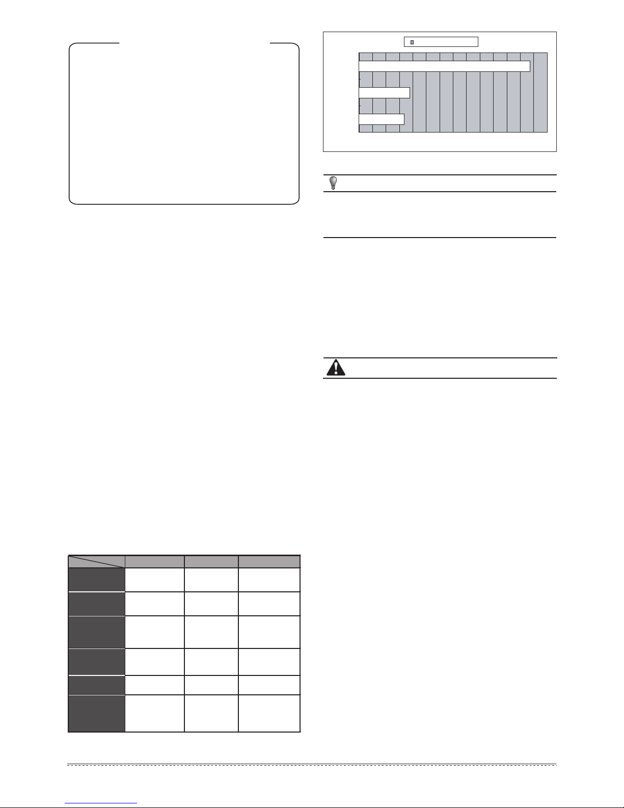
NOTE
Above calculations are based on ideal conditions, the final
amount will be different the actual running will vary with
conditions, such as running period, ambient temperature, etc.
0 1 2 3 4 5 6 7 8 9 10 11 12 13
HPWH
Gas Burner
E-heater
Running Cost AUD
Fig.1-1
1. BASIC OPERATION PRINCIPLE
We know from experience, the natural flow of heat, moves from a
higher to a lower temperature source, a heat pump can transfer heat
from a lower temperature source to a higher temperature source with
high efficiency.
The advantage of a heat pump water heater is that it can supply more
heat energy,
normally 3:1 times than input electricity power by
extracting the heat from ambient atmosphere in a free-of charge way
and transfer to Sanitary Hot Water. Compared to a traditional water
heater, such as electric water heater or gas burner water heater, their
efficiency is normally less than 1:1, which means you can dramatically
cut off the bill of family daily SHW by the application of heat pump
water heater, the following examples will show more details.
Power consumption comparison under the same condition to heat 1
ton of water from 15˚C to 55˚C.
Q=cM(T1-T2)=1(kCal/kg*℃)X1000(kg)X(55-15)(℃)=40000kCal=168MJ
=46.67kW*h
1
1
2
4
6
9
12
14
15
16
BASIC OPERATION PRINCIPLE..............................................................
SAFETY INFORMATION..........................................................................
BEFORE INSTALLATION.........................................................................
INSTALLATION......................................................................................
TRIAL-RUNNING....................................................................................
OPERATION ..........................................................................................
TROUBLE SHOOTING.............................................................................
MAINTENANCE......................................................................................
SPECIFICATIONS...................................................................................
MIDEA– HEAT PUMP MANUFACTURER’S WARRANTY..........................
Table 1-1
HPWH Gas Burner E-heater
Energy
Resource
Air,Electricity Gas Electricity
Transfer Factor 860kCal/kW*h
8905kCal/m
³
860kCal/kW*h
Average
Efficiency
(W/W )
3.5 0.8 0.95
Unit Cost 0.25 AUD/kW*h
1.7C/MJ
0.25 AUD/kW*h
Running Cost
AUD
12.28 3.573.33
13.33kW*h 210MJ 49.13 kW *h
Energy
Consumption
Page 5
2
Installation & Owner‘s Manual
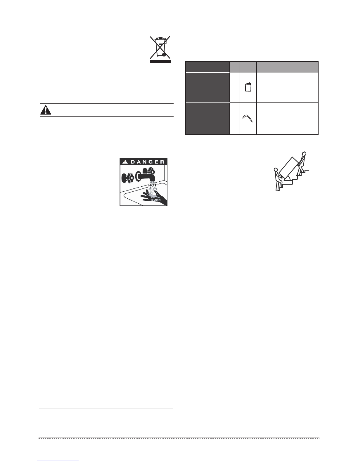
Table 3-1
Accessory Name Qty. Sharp Purpose
1
Owner’s & Installation
Manual
Installation and use instruction
This manual
1
Drain pipe for
water condensation
Use for draining the condensate
water (Has been connected to
the lower condensate drain port)
● If the supply cord is damaged, it must be replaced by the
manufacturer or its service agent or a similarly qualified person.
●
DISPOSAL: Do not dispose this product as
unsorted municipal waste. Collection of such
waste separately for special treatment is necessary. Do not dispose of electrical appliances as
unsorted municipal waste, use separate collection facilities. Contact your local government for
information regarding the collection systems
available.
● If electrical appliances are disposed of in landfills or dumps,
hazardous substances can leak into the groundwater and get
into the food chain, damaging your health and well-being.
3. BEFORE INSTALLATION
3.1 Unpacking
3.1.1 Accessories
3.1.2 How to transport
1) In order to avoid scratching or deforming
the unit surface, apply guard boards
to the contacting surfaces.
No contact of fingers and other things
with the vanes.
Don’t incline the unit more than 75°
in moving, and keep it vertical when
installing.
2) This unit is heavy, it needs to be carried by two or more persons,
othewise might cause injury and damage.
3.2 Location requirements
1) Enough space for installation and maintenance should be
preserved.
2)
The air inlet and outlet should be free from obstacles and strong
wind.
3) The base surface should be flat, surface should be inclined no
more than 2° and able to bear the weight of the unit and suitable
for installing the unit without increasing noise or vibration.
4) The operating noise and air flow expelled should not affect
neighbors.
5) No flammable gas nearby.
6) It should be convenient for piping and wiring.
7)
If it is installed in indoor space, it might cause indoor temperature
to decrease and noise, Please take preventive measures for this.
8) If the unit has to be installed on a metal part of building, make
sure the electric insulation meets the relevant local electric
standard.
>75°
Gradient limit>75°
CAUTION
● The earthing pole of socket must be well grounded, make sure
that power supply socket and plug are dry and connected tightly.
●
Before cleaning, be sure to stop the operation and turn the
breaker off or pull out the power plug. Otherwise, an electric
shock and injury may be caused.
● Water temperature over 50℃ can
cause severe burns instantly or
death from scalds.
Children,
disabled and elderly are at
highest risk of being scalded.
Feel water before bathing or
showering. Water temperature
limiting valves are required as
per AS 3500.
● Do not operate the unit with a wet hand. An electric shock may
be caused.
● The installation height of power supply should be over 1.8m, if
there is any water exposure, steps must be taken to separate
the power supply from water.
● A one-way valve must be installed on the water inlet side, as
well as an isolation value.
● It is normal for some water to be released from the PTR valve
during operation. But, if there is a large volume of water, call
your service agent for instructions.
After long term use, check
the unit base and fittings. If damaged, the unit may sink, resulting
in injury. Arrange the drain pipe to ensure smooth draining.
Improper drainage work may cause wetting of the building,
furniture etc. Do not touch the inner parts of the controller or
remove the front panel. Some parts inside are dangerous to
touch, and damage may be caused.
●
Do not turn off the power supply.
System will stop or restart heating automatically. A continuous
power supply for water heating is necessary, except service
and maintenance.
Hydrogen gas is extremely flammable, and may build up if no
water is drawn of for several weeks.
To reduce the risk of
injury under these conditions, it is recommended that the hot
water tap is opened for several minutes at the kitchen sink
before using any electrical appliance connected to the hot
water system. When hydrogen is present, there will probably
be an unusual sound such as air escaping through the pipe as
the water begins to flow. There should be no smoking or open
flame near the tap at the time it is open.
Page 6
3
Installation & Owner‘s Manual
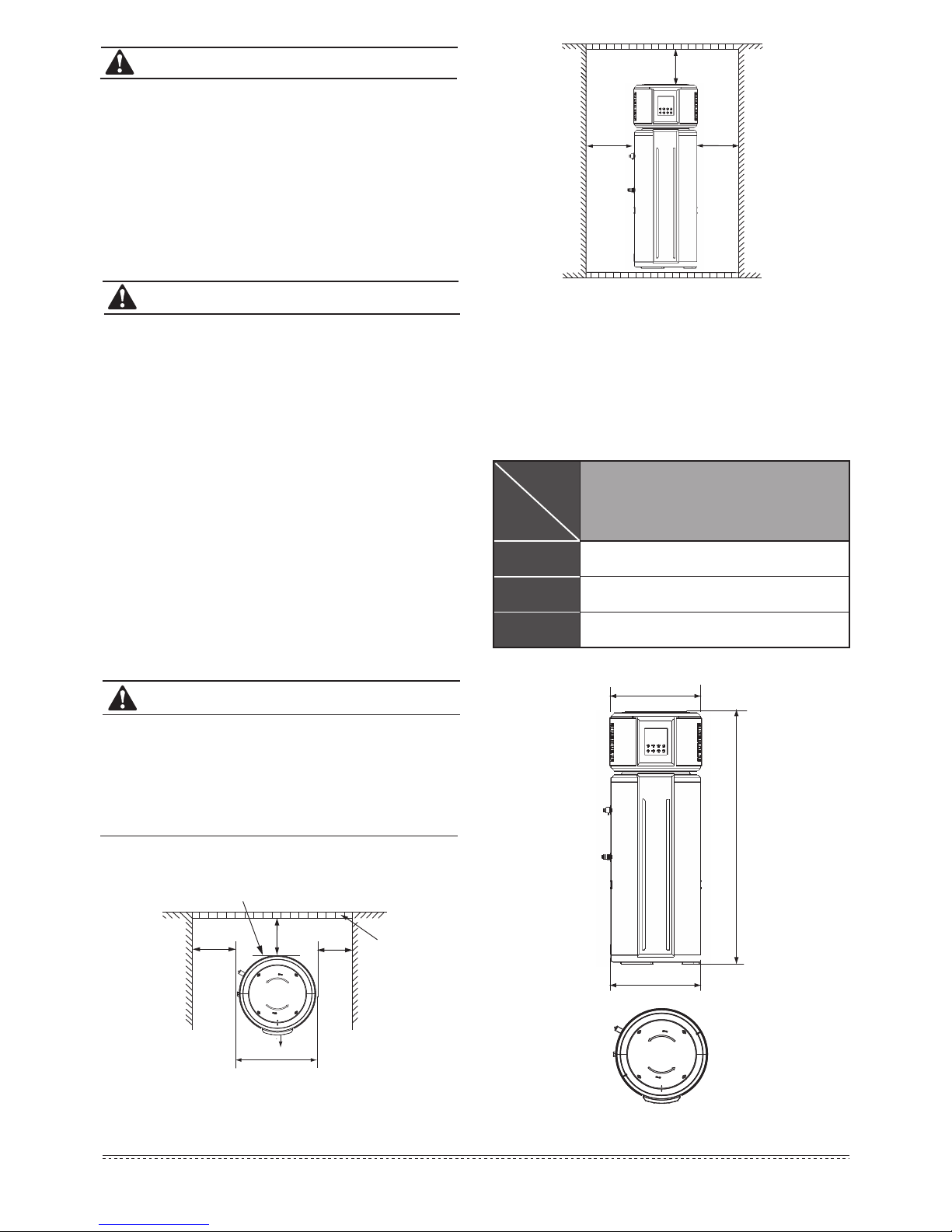
3.4 If installed in inclosed space
The water heater must be located in a space >15m³, and must have
unrestricted air flow. As an example, a room that has an 2.5 tall
ceiling and is 3 meter long by 2 meter wide would contain 15m³ .
3.5 Unit outline dimension (unit: mm)
Fig.3-2
Fig.3-1
ΦA
H
ΦB
Table 3-2
H 1580
ΦA
552
568
Φ
B
RSJ-15/190RDN3-E
Dimension
Model
≥600
≥500
≥300
3.3 Maintenance space requirements (unit: mm)
● The ambient air temperature must also be considered when
installing this unit, in heat pump mode the ambient air temperature must be above 5℃ and below 43℃.If the ambient air
temperature falls outside these upper and lower limits,the
electrical elements will activate to meet the hot water demand
and the heat pump will not operate.
●
The unit should be located in an area not subject to freezing
temperatures. A unit located in unconditioned spaces (i.e.,
garages, basements, etc.) may require the water piping, condensate piping, and drain piping to be insulated to shelter agianst
freezing.
CAUTION
CAUTION
WARNING
● The unit must be securely fixed, otherwise, noise and vibartion
may result.
● Make sure that there are no obstacle around the unit.
● In places where there are strong winds like seaside, fix the unit
in a location protected from the wind.
Installing the unit in any of the following places may lead to
malfunction (If it is inevitable, consult the supplier prior to purchase).
● The site contains mineral oils such as lubricant of cutting
machines.
● Seaside or where the air contains salt.
● Hot spring area where corrosive gases exist, e.g., sulfide gas.
● Factories where the power voltage fluctuates seriously.
● Inside a car or cabin.
● Places with direct sunlight and other heat supplies. If there’s no
way to avoid these, please install a cover.
● Places like kitchen where oil may permeate system.
● Place where strong electromagnetic fields exist.
● Place where flammable gases or materials exist.
● Place where acidic or alkaline gases exist.
● Other special environments.
Display
Barrier
≥600
600
≥300
≥300
Air outlet
Page 7

4
Installation & Owner‘s Manual
4. INSTALLATION
The circulating air for every unit should be more than 350m3/h. Make sure there is enough installation space. Refer outline dimensional drawing
(see Fig.3-1,Fig.3-2)
4.1 Water System Piping
3) Installation of the One Way Valve: The one way valve thread is
RC3/4”. It is used to prevent water from flowing backwards.
4)
After conection of the water system piping work, turn on the cold
water inlet valve and hot water outlet valve and bleed all air from
the tank. When water flows smoothly out from water outlet pipe(tap
water outlet), the tank is full, turn off all valves and check pipeline
to make sure there is no any leakage.
5) If the inlet water pressure is less than 0.15MPa, a pump should be
installed at the water inlet.
To guarantee the safe usage of tank, a reducing valve should be
installed in the water inlet pipe if the water pressure exceeds
500kPa.
6) Condensate may leak from unit if drainage pipe is blocked, a
drainage pan is recommended as shown as following figure:
Fig.4-1
1) Installation of the water inlet or outlet pipes: The water inlet &
outlet thread is
G3/4” (external
thread). Pipes must be
heat-resistant and durable.
2) Installation of the pipe for PTR valve: The valve connecting
thread is
RC3/4” (
internal thread). After installation, it must be
confirmed that the drainpipe outlet is exposed in the air. When
drainpipe is joint to the pressure relief orifice of this valve, it must
be confirmed that the flexible drainpipe is downwards vertically
and exposed in the air.
Handle
Drainage
pipe
Note:
Water temperature limiting valve
is recommended for mixing the
inlet cold water with outlet hot
water to prevent burns caused
by hot water
Water Outlet
User
water Inlet
Drain port
Tap
Water in
Shut off
Valve
Shut off
Valve
One Way
Valve
Barrel-drain
expansion tank for pressure
relief(recommended)
PTR Valve
Upper
Condensate Outlet
Lower
Condensate Outlet
Water Temperature
Limiting Valve
WARNING
EXPLOSION
● Do not dismantle the PTR Valve,
● Do not block off the Drainage pipe, it will
cause explosion and injury.
CAUTION
● Piping water system as the above figure. In case of installing
where outside temperatures fall below 5℃, insulation must be
provided for all hydraulic components.
●
The PTR Valve should be operated every
6 month to make sure that there is no
restriction of the valve. Please beware of
the hot water from the valve. The drainage
pipe should be well insulated in order to
prevent water inside pipe from freezing in
cold weather.
Page 8

5
Installation & Owner‘s Manual
4.3.1 Electric Wiring Illustration
CAUTION
4.3 Electric Connection
Fig.4-2
50mm larger than
the dia. of unit
Max. 22mm
Heat Pump
Water Heater
WARNING
4.4 Installation checklist
4.4.1 Location
1) The flooring beneath the water heater must be able
to support
the weight of the water heater when filled with water (286kg full).
2) Located indoors (such as a basement or garage) and in a
vertical position. Sheltered from freezing temperatures.
4.2 Installation verticality requirement
To smoothly drain condensate from unit, please install the main unit is
on a horizontal floor. Otherwise, please ensuring the drain vent is at
the lowest place. Recommended inclination angle of unit to the ground
should be no more than 2°.
●
Set the electric leakage protector according to the relevant
electric technical standards of the State.
●
The power cord and signal cord shall be laid out neatly and
properly without mutual interference or contacting the connection pipe or valve.
● After wire connection, check it again and make sure of connec-
tion before power is turned on.
Fig.4-3
Drain
≤2
o
Drain
The unit must be installed with an RCD near the power supply
and must be effectively earthed.
Fig.4-4
T3:
Evaporator Temp. Sensor
T4:
Ambient Temp. Sensor
T5L:
Tank Temp. Sensor
TP: Discharge Temp. Sensor
Earthing
TH: Suction Temp. Sensor
Ambient temperature sensor
Suction temperature sensor
CN20
SW3
SW3-2
SW2
SW2-1
Without
2150W
1070W 3200W
1600W
Fan capacitor
Page 9

Installation & Owner‘s Manual
6
5.1 Water affusion before operation
5. TRIAL-RUNNING
Water Affusion
Hot water outlet
Close
Water out
When water flows out from the water
outlet, the tank is full. Turn off the hot water
outlet valve and water affusion is finished.
Open
Open the cool water inlet valve and the hot
water outlet valve.
Cool water inlet
Hot water outlet
Open
Fig.5-1
Before using this unit, please follow the steps below.
Water Affusion: If the unit is used for the first time or used again after
emptying the tank, please make sure that the tank is full of water
before turning on the power.
Method: see Fig.5-1.
CAUTION
Close
Open
Drainpipe shut-off valve
Open
Cool water inlet
Close the cool water inlet valve, open the hot
water outlet valve and open drainpipe.
Hot water outlet
●
After powered on, the display lights up. Users can operate the
unit through the buttons under the display.
●
Emptying: If the unit needs cleaning, moving etc, the tank
should be emptied.
Method: See Fig.5-2:
●
Operation without water in water tank may result in the damage
of auxiliary e-heater. In case of such damage, the manufacturer
will not be liable for any damages caused by this issue.
3) Provisions made to shelter the area from water damage.
Metal drain pan installed and piped to an adequate drain.
4) Sufficient room to service the water heater.
5)
Sufficient air for the heat pump to function, the water heater
must be located in a space >15m³, and must have unrestricted
air flow.
6) The unit cannot be placed into any type of closet or small
enclosure.
7) The site location must be free from any corrosive elements in
the atmosphere such as sulfur, fluorine, and chlorine. These
elements are found in aerosol sprays, detergents, bleaches,
cleaning solvents, air fresheners, paint, and varnish removers,
refrigerants, and many other commercial and household
products. In addition excessive dust and lint may affect the
operation of the unit and require more frequent cleaning.
8) The ambient air temperature must be above 5ºC and below
43ºC.If the ambient air temperature falls outside these upper
and lower limits the electrical element will be activated to
meet the hot water demand.
4.4.2 Water System Piping
1) PTR valve (Temperature and pressure relief valve) properly
installed with a discharge pipe run to an adequate drain and
sheltered from freezing.
2) All piping properly installed and free of leaks.
3) Unit completely filled with water.
4)
Tempering valve installed per manufacturer’s instructions.
Condensate Drain Line Installed.
Must be located with access to an adequate drain or
condensate pump.
Condensate drain lines installed and piped to an adequate
drain or condensate pump.
4.4.3 Electrical Connections
1) The water heater requires 220~240 VAC for proper operation.
2) Wiring size and connections comply with all local applicable
codes and the requirements of this manual.
3) Water heater and electrical supply are properly grounded.
4)
Correctly sized overload fuse or circuit breaker protection
installed.
4.4.4 Post Installation Review
1) Understand how to use the User Interface Module to set the
various modes and functions.
2)
Understand the importance of routine inspection/maintenance
of the condensate drain pan and lines. This is to help prevent
any possible drain line blockage resulting in the condensate
drain pan overflowing.
3)
IMPORTANT: Water coming from the plastic shroud is an
indicator that both condensation drain lines may be blocked.
Immediate action is required.
4)
To maintain optimal operation check, remove and clean the air
filter.
Page 10

7
Installation & Owner‘s Manual
Fig.5-2
Emptying
Drainpipe shut-off valve
Close
After emptying, please replace the nut of
drainpipe.
5.2 Trial- running
5.2.1 Check list before commissioning.
1) Check list before trial-running.
2) Correct installation of the system.
3) Correct connection of water/air piping and wiring.
4) Condensate draining smoothly well insulated for all hydraulic
part.
5) Correct power supply.
6) No air in the water pipeline and all valves opened.
7) Effective RCD installed.
8) Sufficient inlet water pressure (between 0.15MPa and 0.65MPa)
(150-650kPa).
5.2.2 About Running
1) System Str
ucture Figure
This unit has two kinds of heat sources: Heat pump
(compressor) and electric heater.
The unit will automatically select heat sources to heat water to
the target temperature in different mode.
2) Water Temperature Display
The temperature shown on the display depends on the water
temperature sensor. It is normal that sometimes the display temperature decreases while the unit is running, it is caused when the
natural convection of the upper hot wate mixes with by the bottom
cold water which flows from inlet tap.
3)
Operating mode should be selected manually. Refer to table 5-1.
Running Temperature Range
Water temperature limits:
Tank
Water temperature sensor
Electric heater
Water inlet
Water outlet
Fig.5-3
③ Defrosting During Water-heating
In heat pump running period, if the evaporator becomes frosted in
lower ambient temperature, the system will defrost automatically
to keep effective performance (about 5~15min). At defrosting time,
the compressor will stop, but fan motor will still run.
④ Heat-up Time
There are different heat-up times at different ambient temperatures. Normally lower ambient temperature result in longer heat-up
times because of lower effective performance.
4) Heat Source Shift
①
The default heating source is heat pump.
If ambient temperature range is out of heat pump operating range,
heat pump will stop running, the unit will shift automatically to activate
E-heater and show the icon LA on the display, then if the ambient
temperature goes into the running range of heat pump again, it will
stop E-heater and shift automatically to heat pump again, and the
icon LA will be extinguished.
②
If the target water temperature is higher than maxinum temperature (Heat pump), the unit will activate heat pump firstly to the
maxinum temperature, then stop heat pump, activate E-heater to
continually heat water to the target temperature.
NOTE
If only using E-heater mode, approx 60% of the tank water will be
heated, so set a higher target water temperature if the ambient
temperature is out of the heat pump running range.
NOTE
If the system continuously reports heat pump protection, the latest
error code and will be shown on the display, then heat pump will
stop running, and the unit will shift automatically to E-heater mode
as the backup mode, but the code and will be shown until power
is reset.
--
65
Ambient temp.
range
Maxinum temp.
(Heat pump)
Table 5-1
Setting temp.
range
Operation
mode
Economy mode
Hybrid mode
E-heater mode
5~43
-20~43
-20~43
38~70
38~65
38~70
65
Page 11

8
Installation & Owner‘s Manual
NOTE
While the ambient temperature is below 5℃, heat pump
efficiency will decrease dramatically, the unit will automatically
shift to E-heater mode.
⑤ About TCO and ATCO
The power of compressor and E-heater will be automatically
shut-off or turn on by TCO and ATCO.
● If the water temperature is higher than 78℃, the ATCO will automati-
cally shut off the power of compressor and E-heater, and turn it on
it if the temperature fall down below 68℃.
●
If the water temperature is higher than 85℃, the TCO will automati-
cally shut off the power of compressor and E-heater, it must be
reset by an authorised service technician.
⑥
Restart After a Long Term Stop
When the unit is restarted after a long term stop (trail running
included), it is normal that outlet water is unclean. Turn the tap on
and the water will be flushed clean.
5.2.3 Basic function
1) Weekly disinfect function
Under disinfection mode, unit immediately starts to heat water up
to 65℃ to kill any potential of legionella bacteria inside water of
tank, icon will light on the display screen during disinfection;
Unit will quit disinfection mode when water temperature is higher
than 65℃ and extinguish icon.
2) How to turn on the unit:
I
f unit is OFF->press ->button will be unlocked ->press
to select mode ->press to set target water
temperature->press ->unit will automatically select mode
and start to heat water to target temperatur
e.
Fig.5-4
500
1000
1500
2000
2500
3000
5715202530323540
43
Capacity(W)
Ambient temp(℃)
15-45
15-55
15-65
Fig.5-5
1
2
3
4
5
6
7
5 7 1 5 20 25 30 32 35 40 43
COP(W/W)
Ambient tem p(℃)
15-45
15-55
15-65
Fig.5-6
0 :00: 00
2 :24: 00
4 :48: 00
7 :12: 00
9 :36: 00
12: 00: 00
14: 24: 00
5715202530323540
43
Time(h)
Ambient tem p(℃)
15-45
15-55
15-65
Page 12

9
Installation & Owner‘s Manual
6. OPERATION
6.1 Control Panel Explanation
6.2 Display Explanation
Fig. 6-1
Display
Operation
Fig.6-2
① ② ③ ④ ⑤ ⑥ ⑦ ⑧ ⑨
10
11
12
13 14 1615 17 18 19
11
10
12
13
⑤
⑥
⑦
⑨
⑧
WATER TEMP:
will be
displayed
all the time.
shows water temperature on normal time;
shows setting temperature when setting
temperature;
shows unit setting/running parameters,
error/protection code under query mode.
No Icon Description
DISINFECTION:
will be displayed when the unit is in
disinfection mode, otherwise will be
extinguished.
LOCK:
will be displayed if buttons are locked,
otherwise will be extinguished.
ECONOMY MODE:
will be displayed if unit is operating
in Economy Mode. When selecting mode,
will flash with 1Hz frequency if
Economy Mode is selected at the off time.
HYBRID MODE:
will be displayed if unit is operating
in Hybrid Mode. When selecting mode,
will flash with 1Hz frequency if
Hybrid Mode is selected at the off time.
E-HEATER MODE:
will be displayed if unit is operating
in E-heater Mode. When selecting mode,
will flash with 1Hz frequency if
E-heater Mode is selected at the off time.
ALARM:
When unit is displaying protection/error,
will flash with 5Hz frequency as well as
buzzer sounding 3 times every minute until
protection/error eliminated or press for 1
second.
HIGH TEMP:
If target water temp. is higher than 50℃,
will be lightened , otherwise will be
extinguished.
FILL WATER:
will be displayed and flash with 1Hz
frequency when the unit is re-powered on if
the unit was off at last time of power on,
then if press once, will be displayed
without flashing,then press again, will
be extinguished all the time. will not be
displayed when the unit is re-powered on if
the unit was on at last time of power on.
TEMP-UNIT:
will be
displayed
if displays temperature,
otherwise will be extinguished.
Table 6-1
①
②
③
AMBIENT TEMP OUTSIDE THE OPERATIONAL
RANGE OF HP:
will be displayed if the ambient temp. is
not in the operating range of the heat pump,
otherwise will be extinguished.
④
WIRE CONTROLLER (Reserved function):
will be displayed if connected to a wire
controller, otherwise will be extinguished.
COMPRESSOR:
will be displayed if compressor is activated,
otherwise will be extinguished.
No Icon Description
E-HEATER:
will be
displayed
if e-heater is activated,
otherwise will be extinguished.
14
Page 13

10
Installation & Owner‘s Manual
Fig. 6-3
6.2.1 Operation interface
20 21 22 23 27
24 25 26 28
Table 6-2
21
20
23
22
24
Mode Selection
Press button to select operation mode. The
unit can operate with three modes: Economy
Mode, Hybrid Mode and E-heater Mode.
Economy mode is the normal mode.
ECONOMY MODE:
The unit can heat water only by heat pump
system in this mode. The suitable operation ambient
temperature range is 5~43℃.
HYBRID MODE:
The unit can heat water by heat pump system,
e-heater, or together in this mode. The suitable
operation ambient temperature range is -20~43
℃. In this mode, if ambient temperature is lower
than 5℃, e-heater is the only heat source. If the
ambient temperature is between 5℃ and 10℃,
e-heater and the heat pump will active together.
If the ambient temperature is higher than 10℃, it
will only activate the heat pump when water
temperature is lower than 65℃ and only active
e-heater when water temperature is higher than
65℃.
E-HEATER MODE:
The unit can heat water only by e-heater in this
mode. The suitable operation ambient temperature range is -20~43℃.
Cancel
Unlock Control Panel:
In order to prevent wrong operation, a
special lock function has been designed. If
there is no operation for 1 minute, control
panel will be locked automatically, and
display the lock indicator . If the control
panel is locked, no button can be operated.
Press button for 3 seconds to unlock,
then all buttons could be operated normally.
15
16
17
18
19
SET-TEMP:
will be displayed when setting water
temp., otherwise will be extinguished.
OPERATION INDICATOR:
will be
displayed
if unit is ON, otherwise
will be extinguished.
CLOCK:
will be displayed all the time.
shows current clock on normal time;
shows setting clock when setting timer.
TIME CONFLICT (Reserved function):
will be displayed if the timer which has
been set on the control panel is not the same
as that set on the ware controller.
TIME OFF:
will be displayed if the timer is set.
TIME ON:
will be displayed if the timer is set.
Set Clock
The clock is for a 24-hour system and the initial
time is 00:00. To make a better use of this unit,
it is recommended to set the time for accurate
local time. Every time powered off, the clock will
be reset to the initial time 00:00.
Press the button to enter clock
setting, the hour value of clock will
flash slowly.
Press the button again or no
operation for 10 second, flashing will
stop and confirm the clock setting.
Press the button again, confirm
the hour setting. Then the minute
value of clock will flash slowly.
Set the hour value of clock.
Set the minute value of clock.
Auto-operation
If tank is full of water, press the button ,
the indicator will stop flashing and you
can continue to adjust other settings.
When all settings finished, press the button
again and the indicator will be
extinguished. And then the unit will operate
automatically.
CAUTION
ON/OFF
Press button can
turn on or turn off the unit.
Preparation before running the unit.
When the unit is powered on for the first time, all
the indicators on the display will be displayed for 3
seconds and the buzzer will “didi” ring twice at the
same time, then, display the nominal page. After
no operation for 1 minute, all indicators will be
extinguished automatically except indicator
(flash slowly) and water temperature. Buzzer will
“di” ring when you press any button.
Confirm the tank is full of water or
not when indicator is flashing.
Page 14

11
Installation & Owner‘s Manual
25
26
Set Timer-TIME ON ONLY
Time on only:
If the Timer is set to TIME ON, the unit will
automatically operate once between the setting
of the clock and the last 24 hours.
Cancel Timer-TIME ON ONLY
In the unlocked state, press the button for 3
second and the Timer-TIME ON function will be
canceled.
Set Timer-TIME ON & TIME OFF
Time on & Time off:
If set the Timer-TIME ON & TIME OFF, the unit
will automatically operate between the setting
TIME ON clock and TIME OFF clock.
If the TIME OFF clock is the same as TIME ON
clock, TIME OFF clock will be delayed 10
minutes automatically.
Press the button to enter
Timer-TIME ON setting. the hour
value of the clock will flash slowly.
Pressing the button again or no
operation for 10 second, flashing will
stop and confirm the Timer-TIME ON
setting.
Press the button again, confirm
the hour setting. Then the minute
value of clock will flash slowly.
Set the hour value of clock.
Set the minute value of clock.
Set the hour value of clock.
Set the minute value of clock.
27
28
Cancel Timer-TIME ON&TIME OFF
In the unlocked state, press the button for more
than 3 seconds and the Timer-TIME ON & TIME OFF
function will be canceled.
INCREASE/UP
If button is unlocked, corresponding value will
increase by pushing .
● When setting temperature, press for more
than 1s, temperature value will be increased
continuously;
● When Setting clock/timer, press for more
than 1s, Clock/timer value will be increased
continuously.
DECREASE/DOWN
If button is unlocked, corresponding value will
decrease by pushing .
● When setting temperature, press for more
than 1s, temperature value will be decreased
continuously;
●
When Setting clock/timer, press for more
than 1s, Clock/timer value will be decreased
continuously.
Press the button to enter
Timer-TIME OFF setting. the hour
value of the clock will flash slowly.
Press the button again, confirm
the hour setting. Then the minute
value of clock will flash slowly.
Pressing the button again or no
operation for 10 second, flashing will
stop and confirm the Timer-TIME
OFF setting.
Press the button to enter
Timer-TIME ON setting. The hour
value of the clock will flash slowly.
Pressing the button again or no
operation for 10 second, flashing will
stop and confirm the Timer-TIME ON
setting.
Press the button again, confirm
the hour setting. Then the minute
value of clock will flash slowly.
Set the hour value of clock.
Set the minute value of clock.
Page 15

12
Installation & Owner‘s Manual
6.3 Combination button
7. TROUBLE SHOOTING
7.1 Non-error tips
Q: Why can’t the compressor start immediately after setting?
A: Unit will wait for 3 min to balance the pressure of system before
starting compressor again, it is a self protection logic for the unit.
Q: Why is the temperature shown on the display panel sometimes
decrease while unit is running?
A: When the upper tank temperature is much higher than the bottom
part, upper part hot water will be mixed with the bottom cold water
which flows from inlet tap water, so that will decrease the average
temperature.
7.2 Something about self-protection of unit
1) When the self-protection mode activates, the system will be stopped
and start a self-check, and restart when the error is resolved.
2)
When the self-protection mode activates, the buzzer will buzz
every second minute, the will flash and error code will be
Table.7-1
Error
phenomenon
Possible reason solution
Cold water
out and
display screen
extinguished
No hot water
out
Water leakage
Hydraulic pipeline joints
are not sealed well.
Bad connection
between power supply
plug and socket;
Setting water
temperature too low;
Temper sensor broken ;
PCB of indicator broken;
Compressor broken.
1. Plug in;
2. Setting water temp. higher;
3. Contact service center.
Waiting for public water
supply recover;
Waiting for inlet water
pressure increase;
Open water inlet valve.
Check and reseal all joints.
Public water supply
ceased;
Cold water inlet pressure
too low (<0.15 Mpa);
Cold water inlet valve
closed.
1.
2.
3.
1.
2.
3.
1.
2.
3.
6.4 Auto-restart
If power is disconnected, the unit can remember some of the setting
parameters (On or Off state, operating mode, setting water temperature); when it re-powers on, the unit will be operated as per the
previous settings.
6.5 Button Auto Lock
When there is no operation of button for 1 minute, buttons will be
locked except Unlock button , Press for 3s, unlock buttons.
6.6 Screen Auto Lock
If there is no operation of button for 30s, screen back light will be
extinguished.Press any button will lighten the screen back light.
No. Icon Description
Clear error
code
Query
mode
+
+
Press the two buttons at
the same time to clear all
stored error & protect
codes, and the buzzer
will buzz one time.
Press the two buttons at
the same time for 1sec
to go into query mode.
Under query mode user
can check unit setting &
running parameters by
pressing
circularly. Press button
for 1s or no
button operation for 30s,
then quit query mode.
shown at water temperature indicator. Press button for 1sec
to stop buzz, but the and error code will not disappear until the
error is resolved.
3)
In the following circumstance, self-protection may happen:
If air inlet or outlet is blocked;
If the evaporator is covered with too much dust;
Incorrect power supply (exceeding the range of 220-240V).
7.3 When Error happens
1) If some cases of error happen, the unit will automatically shift to
E-heater for emergency SHW supply, please contact authorised
technician to repair.
2) In case of serious errors, the unit will not start, please contact
authorised technician to repair.
3)
For some errors, the buzzer will buzz 3 times every other minute
and the will flash fast. Press for 1 sec to stop the buzzer
but the alarm icon will keep flashing.
7.4 Trouble shooting
Page 16

13
Installation & Owner‘s Manual
The diagnostic codes listed above are the most common. If a diagnostic code not listed above is displayed, contact
residential technical assistance referencing the number on the front of this manual.
NOTE
7.5 Error code shooting table
Table.7-2
Malfunction Description Corrective action
Error of sensor T5L(lower water temperature sensor)
E1
Maybe the connection between sensor and PCB is
broken or sensor has been broken.
Contact a qualified person to service the unit.
Tank and wired controller communication error
E2
The connection between controller and PCB is
broken or PCB has been broken.
Evaporator temperature sensor T3 error
E4
The connection between sensor
and PCB is
broken or sensor has been broken.
Contact a qualified person to service the unit.
Ambient temperature sensor T4 error
E5
The connection between sensor and PCB is
broken or sensor has been broken.
Contact a qualified person to service the unit.
Compressor discharge temperature sensor TP error
E6
The connection between sensor and PCB is
broken or sensor has been broken.
Contact a qualified person to service the unit.
E
8
Some wires have been broken or bad wiring
connection.
Contact a qualified person to service the unit.
If PCB current_induction_circuit check the current
difference between L,N >14mA, system consider it as
"electric leakage error"
Electric leakage error
Compressor suction temperature sensor TH error
E9
The connection between sensor and PCB is
broken or sensor has been broken.
Contact a qualified person to service th
e unit.
E-heater open-circuit protection (IEH(Current difference
E-heater on & e-heater off )<1A)
Maybe the E-heater has been broken or bad wiring
connection after repair.
P2
High discharge temperature protection
Tp>115℃,Protection active
Tp<90℃,Protection inactive
System blocked, air or water or low
refrigerant(leakage) in system (after repair), water
temperature sensor malfunction, etc.
Contact a qualified person to servic
e the unit.
Compressor overloaded protection (10 secs after
compressor start up), Current checking starts ,
1)only compressor running, if it is >7A , the
compressor will be stopped and protected.
2)Compressor+e-heater opend, if it is >IEH+7,the
compressor will be stopped and protected.
Compressor broken, system blocked,
air or water or too much refrigerant in system (after
repair), water temperature sensor malfun
ction, etc.
℃
When the ambient temp T4 is out of Heat Pump
running range (5~43℃) Heat Pump will stop, unit will
show LA on the position of clock on display until T4
back to (5~43 ).
It is normal, and not necessary to repair.
Display
E1
E2
E4
E5
E6
E8
E9
P8
P2
P4
LA
Page 17

14
Installation & Owner‘s Manual
8.2 Recommended regular maintenance table
Checking
Item
Checking
content
Checking frequency Action
1
air filter
(inlet/outlet)
every month Clean the filter
2 anode rod every half year Replace if required
3 inner tank every half year Clean the tank
4
5
e-heater every half year Clean e-heater
Operate the
hander of PTR
valve to ensure
that waterways
are clear.
PTR valve
If water doesn't flow freely when operating the
handle, replace PTR valve with a new one
every year
Table.8-1
8. MAINTENANCE
8.1 Maintenance
1) Check the connection between power supply plug and socket
and ground wiring regularly;
2) In some cold areas (below 0℃), if the system will be stopped for
a long time, all the water should be released in case of freezing
of inner tank and damage of E-Heater.
3) It is recommended to clean the inner tank and E-Heater
regularly to keep an efficient performance.
① Cut off the power.
② Close the cold water inlet valve, open the hot water tap.
③ Use a flexible pipe to connect the drain port to a suitable sewage
draining exit. (The min. heat resistance of the drain pipe is not
less than 93℃, if the drain pipe can not meet the requirement,
please open the cold water inlet valve, open the hot water tap,
until there is no hot water flow out.)
④ Open the drain port of the water heater; drain out all the water in
the inner tank. If it is needed, use water to wash the inner tank
several times to clear the deposits.
⑤ Close the drain port, re-fill the inner tank with water, and
re-power on.
4) Check the anode every half year and change if required. For
more details, please contact the supplier or the service.
How to Change the anode
● Turn off the power, and turn off the water inlet valve.
● Open hot water tap, and decrease the pressure of the inner
container.
● Open the drain port, and release about 20L water.
● Unscrew anode according to instruction.
● Replace with a new one, and make sure effective sealed.
● Open cold water valve until hot water flows out, and turn off the
hot water tap.
● Restart and can be used normally.
NOTE
How to Take Off The Air Filter,remove screw from top cover.
Take the top cover,
and slide out the filter
Rotate top cover
counter clockwise
When installing the top cover please refer to the
direction of arrow, after assembling it should be line
up.
NOTE
Page 18

15
Installation & Owner‘s Manual
9. SPECIFICATIONS
The test conditions:
1) Test temperature 15/12℃(DB/WB);
2) Water temperature from 15℃ up to 45℃.
Model
Economy Mode Hybrid Mode E-Heater Mode
E-HeaterHeat Pump
1500W
2150W/9.3A780W/3.4A
2150W
Over-load Protector, Temp Controller&Protector,
Electric Leakage Protector, etc
Outer coil inner water tank
Hydrophilic aluminum fin, inner groove copper tube
40W
Air out from sideward
440W
2150W
1.0MPa
DN20
DN20
DN20
DN20
Default 63℃,(38℃-70℃ adjustable )
T20A 250VAC
Φ568×1580mm
190L
90kg
2780W/12.1A
1500W
2150W
Water pipeline system
RSJ-15/190RDN3-E
Table 9-1
Model
Mode
Hot water heating cap.
Rated input power/current
Power supply
Protection
Compressor power
E-heater power
Outlet water
temp.
Water side
exchanger
Inlet pipe Dia.
Outlet pipe Dia.
Drain water port
Dia.
Safety valve Dia.
Maxinum pressure
Material
Motor power
Outlet air type
Fusible link type
Regrigerant
Dimension
Water tank cap.
Net weight
Exchanger
air side
220-240V~ 50Hz
R134a(800g)
Page 19

Installation & Owner‘s Manual
16
10. MIDEA– HEAT PUMP MANUFACTUR ER’S WARRANTY
This warranty is provided by Midea. It applies to heat pumps installed
in a single family dwelling only and is provided only to those acquiring
the heat pump as consumers within the meaning of the Australian
Consumer Law. The terms of the warranty are effective from the date
the heat pump is installed. Midea may verify this date by requesting a
copy of the compliance certificate that accompanied the installation.
The compliance certificate is mandatory in all Australian states and
territories.
10.1 Warranty period
Midea warrants that the following heat pump components will remain
free of defects for the specified periods from the date of installation:
• Storage Tank - 5 years.
• Compressor- 3 years.
• All other components supplied by Midea, including valves,
elements, thermostats and sacrificial anodes - 1 year.
• Midea gives no warranty in relation to components not supplied by
Midea, for example tempering valves and cold water valve assem-
blies used by installers.
Subject to the conditions and exclusions specified in this warranty,
Midea will at its own expense repair or replace any defective heat
pump component covered by this warranty as soon as reasonably
practicable after the consumer has reported the defect to Midea.
10.2 Consumers must register the warranty
To be eligible to make a claim under this warranty, consumers must
complete all details in the Installation Report & Warranty Registration
form provided with the heat pump within 6 weeks of installation and
send it to the address shown on the form.
10.3 Procedure to make a claim under
warranty
Upon discovering a suspected defect, consumers should immediately
report the suspected defect:
• To the installer or supplier, if the suspected defect arises as a result
of the installation of the heat pump or relates to any components
not covered by this warranty.
• To Midea on the phone number below during the relevant warranty
period, if the suspected defect relates to any components covered
by this warranty.
10.4 Specific exclusions
To the extent permitted by law Midea does not accept liability under
this warranty:
1) If any component of the heat pump has been installed, repaired,
repositioned or modified by a person other than an appropriately
qualified person approved by Midea in accordance with Midea’s
installation and maintenance instructions and relevant local and
statutory requirements;
2)
For loss or damage caused by a fault or defect in the installation
of the heat pump;
3)
If corrosion has occurred because the anode has not been
changed in accordance with the owner’s manual;
4) If a cold water expansion valve, check valve and strainer is not
fitted in areas where mains pressure is likely to exceed 500 kPa;
5) For any damage arising as a result of an accident, act of God or
other circumstances beyond Midea’s control;
6) If the inner cylinder has collapsed as a result of an incorrect filling
and/or commissioning procedure;
7)
For components not supplied by Midea that are used in the installa-
tion of Midea heat pump water heaters e.g. tempering valves, cold
water valve assemblies, etc.
8) For extended or implied warranties not formally provided by Midea;
9) For external labour or equipment costs (e.g. cranes and lifting
devices) required for repairs;
10) For costs incurred for rectifying faults (or perceived faults) not
directly attributed to the Midea heat pump water heater;
11) For travel costs of service agents that exceed 30 kilometres;
12) For all consequential loss or damage arising from defects that can
lawfully be excluded;
13) For any other issues not directly attributable to defects in components supplied by Midea including:
(a) Damage caused by incorrect commissioning;
(b) Leakage from valves not supplied by Midea;
(c) Leakage from the pressure temperature relief valve where the
water pressure or temperature exceeds the limits specified in
Midea’s installation and maintenance instructions;
(d) Water hammer;
(e) External rust on the storage tank;
(f) Insufficient hot water because:
(i) The consumer refuses to use the auxiliary booster;
(ii) Of an incorrectly set or faulty tempering or mixing valve;
(iii) Of faulty or incomplete installation;
(iv) The water heater is too small for its required purpose;
(v) Of insufficient water flow as a result of “water saving” tap-ware or
appliances;
(vi) Of blown fuses, “tripped” electrical switches or inadequate house-
hold electrical wiring;
(vii) Insufficient water flow caused by debris accumulating in water
strainer.
10.5 Important Note
The benefits conferred by this warranty are in addition to any other
rights and remedies available to the consumer under a law in relation
to the goods or services to which the warranty relates.
Midea’s goods come with guarantees that cannot be excluded under
the Australian Consumer Law. Consumers are entitled to a replace-
ment or refund for a major failure and for compensation for any other
reasonably foreseeable loss or damage. Consumers are also entitled
to have the goods repaired or replaced if the goods fail to be of accept-
able quality and the failure does not amount to a major failure.
Contact Phone: 1300 367 565.
Page 20

MDV11IU-055BW(DZ)
2020001A9998
 Loading...