

Midea PREMIER Installation Manual
1. Dete rmine h ole pos ition s accor ding to l eft or ri ght sid e
of the In stall ation P late. Th e hole center is o btained by
measu ring th e dista nce as sh own in th e diagr am abov e.
2. Dril l the pip ing hol e with ¦6 5mm hol e-cor e drill .
3. Dril l the pip ing hol e at eith er the ri ght or th e left an d the
hole sh ould be s light ly slan ted dow n to the ou tdoor s ide.
4. Always t ake ste ps to pro tect th e pipe wh en dril ling me tal
grid, m etal pl ate or th e like.
INSTALLATION MANUAL
PREMIER SERIES
(Split Wall-Mounted Air Conditioner)
DRILL A HOLE IN THE WA LL
INSTALLATION PLATE MOUNTING
2
1
I
N
D
O
O
R
U
N
I
T
Please read the se safety pre cauti ons caref ully befo re instal latio n.
Be sure to follow all the preca ution s below, they are all impor tant for ensu ring safe ty.
This symb ol indica tes the possi bilit y of death or serious inj ury.
This symb ol indica tes the possi bilit y of injury or damage to prop erty.
1) This equipment must be grounded (earthed) and installed with ground leakage current breaker. It
may cause electrical shock if grounding isn ot perfect.
2) Do not install the unit in a place near where leakage of flammable gas may occur. If gas leaks and
accumulates near the unit, it may cause fire. Please follow local council’s guidelines and regulations.
3) Carry out drainage piping as mentioned in installation instructions. If drainage is not perfect, water
may enter the room and damage wall, furniture, floor and carpet.
1) Installation must be strictly in accordance to this installation instructions. If installation is defective, it
will cause water leakage, refrigerant leakage, damage, electrical shock, or fire.
2) Use the included accessories parts and specified parts for installation. Otherwise, it may cause the unit
to fall, water leakage, refrigerant leakage, damage, electrical shock or fire.
3) Install at a strong and firm location which is able to withstand the unit’s weight. If the installation position
is not strong enough orif the installation is not properly done, the set willd rop and cause injury.
4) For electrical work, follow the local national wiring standard, regulation and this installation instructions.
An independent circuit must be used. If electrical circuit capacity is insufficient or if there are defects in
electrical work, it will causeda mage to the unit, electrical shock or fire.
5) Use the specified cable and connect tightly. Clamp the cable so that no external force will be placed
upon the terminal. If connection or fixingi s not perfect, itw illcaus e heat-up or fire at the connection.
6) Wiring routing must be properly arranged so that control board cover is fixed properly. If the control board
cover is not fixed perfectly, it will overheat atthe termina l connection point, causing fire or electrical shock.
7) When carrying out piping connection, ensure that a proper vacuum is achieved and only specified
refrigerant enters the refrigeration cycle. Otherwise, it will cause lower capacity, abnormal high
pressure in the refrigeration cycle, possible explosion and injury.
8) Ensure that the unit is on a dedicated circuit wired to the switchboard with its own isolator and that it is
not on a shared circuit with other electrical appliances. Otherwise, it will cause fire orelect ricalsh ock.
SAFETY PRECAUTIONS
CAU TIO N
WAR NING
CAU TI ON
WA RN IN G
Please read this installation manual carefully to ensure correct installation is carried out.
If the power cord is damaged, replacement work must be performed by qualified personnel.
Electrical work must be performed in accordance with the national wiring standards by licensed
electrical personnel. The installer must hold appropriate refrigeration license for installation of this unit.
Contact an authorised service technician for repair, maintenance and installation of this unit.
This appliance is not intended for use by persons (including children) with reduced physical, sensory
or mental capabilities, or lack of experience and knowledge, unless they have been given supervision
or instruction concerning use of the appliance by persons responsible for their safety.
Children should be supervised to ensure that they do not play with the appliance.
All the illustrations in the instructions are for explanation purposes only. The actual shape may differ.
The design and specifications are subject to change without prior notice for product improvement.
Consult with the sales agency or manufacturer for further details.
There s hould n ot be any h eat sou rce or st ream
near th e unit.
There s hould b e no obst acles b locki ng the ai r
circu latio n.
Selec t a place w here th ere is go od air ci rcula tion.
Selec t a place w here dr ainag e can be ea sily ca rried o ut.
Selec t a place w here no ise pre venti on is tak en into
consi derat ion.
Do not in stall t he unit n ear the d oor way o r windo w.
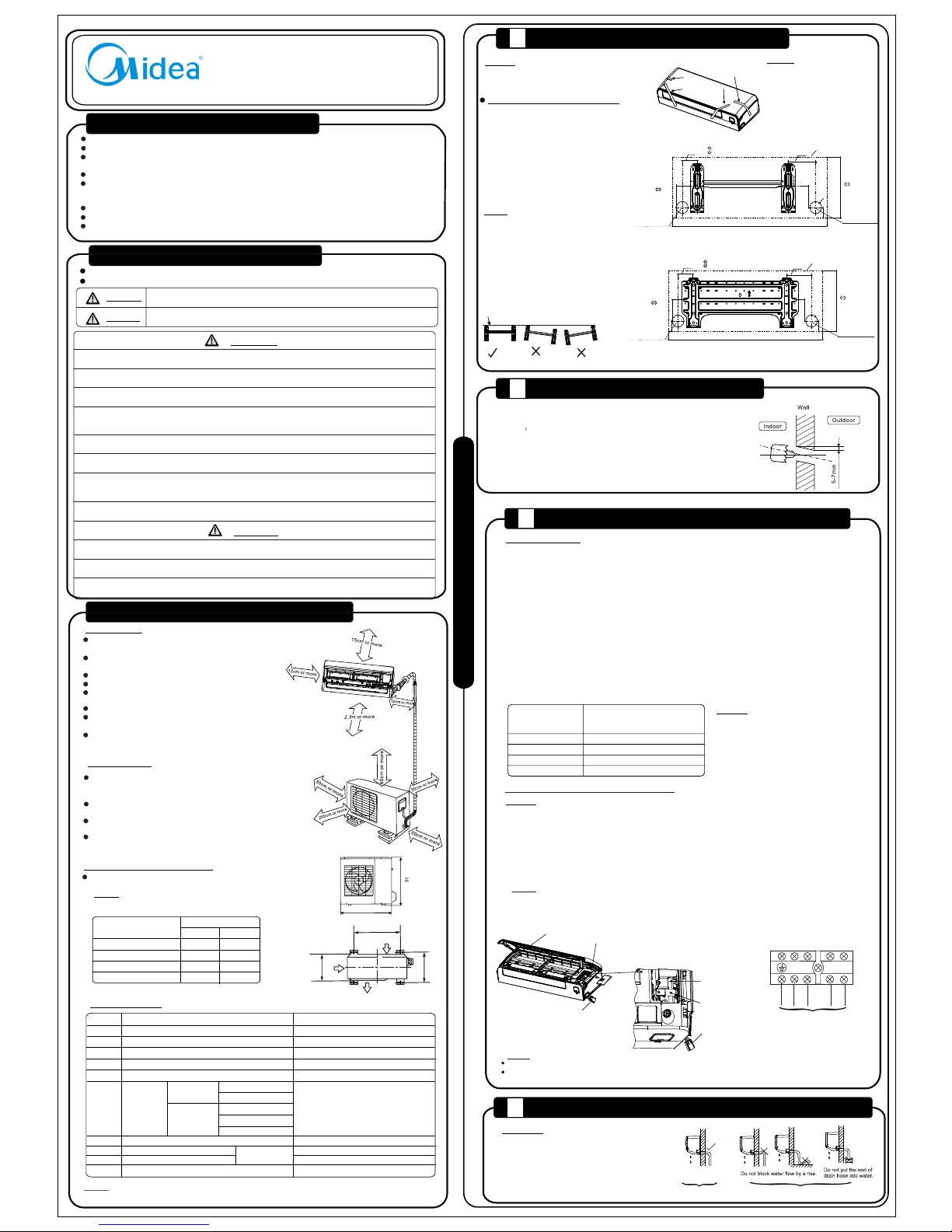
Ensur e there i s suffic ient space, in dicated by arr ows
from ad jacen t wall, c eilin g, wind ow or oth er obst acles .
There s hould b e no dire ct sunl ight on t he unit . If
unavo idabl e, sunl ight pr event ion sho uld be co nside red.
O
ut do
o
r U
n
it D
i
m
e
ns
i
on
m
m
(W
x
Hx
D
)
A( mm) B (mm)
53 0
29 0
56 0
33 5
48 1
54 9
27 6
27 6
Mo unti ng Dime nsi ons
67 0x54 0x2 65
78 0x54 0x2 50
76 0x59 0x2 85
84 5x70 0x3 20
In do or Unit
Ou td oo r Uni t
If an awn ing is bu ilt ove r the uni t to prev ent dir ect
sunli ght or ra in, be ca reful t hat hea t radia tion fr om
the con dense r is not ob struc ted.
There s hould b e no anim al or pla nt near by whic h
could b e affect ed by discharg e of hot or cold air.
Keep th e space s indic ated by a rrow fr om wall
ceili ng, fen ce or oth er obst acles .
Do not pl ace any o bstac les whi ch may ca use
a short c ircui t of the di schar ged air.
Ancho r the out door un it with b olts an d nuts ¦1 0 or ¦8
tight ly and ho rizon tally o n concr ete fee t or rigi d mount .
Se tt le me nt of Ou td oo r Uni t
NOTE: Th e outdoor unit y ou purchase ma y be one of
the fol lowin g. Inst all the o utdoo r unit ac cordi ng to the
dimen sions a s indic ated in t he tabl e below :
A
W
B
D
Air I nlet
Air O utlet
FRO NT
Air I nlet
INSTALLATION PRECAUTIONS
CONNECT THE CABLE TO THE I NDO OR UNIT
3
Mi ni mu m Nom in al Cro ss -S ec ti on al Are a of Con du ct or s :
Rat ed cur re nt
of app li an ce
(A)
>3 and <6
>6 and <10
>10 and <16
>16 and <25
Nom in al cro ss -s ec ti on al
ar ea
(mm 2)
0.75
1
1.5
2.5
The cable siz e and the current of the fuse
or switch are deter mined by the maxi mum
current ind icate d on the nameplat e which
is located on the side pane l of the unit.
Please refe r to the nameplat e before
selecti ng the cable, fus e and switch.
Terminal Block of Indoor Unit
Co nn ec t the Cab le to the Indo or Uni t
NOT E:
Befor e perfo rming a ny elec trica l work, t urn off t he main po wer to the syste m.
1. The ins ide and outsid e connecting c able can be conn ected withou t removing the f ront grille.
2. The ind oor power cord t ype is H05VV-F or H0 5V2V2-F, the outdo or power cord an d
inter conne cted co rd type i s H07RN -F.
3. Lift t he indo or unit p anel up , remov e the ele ctric al box co ver by lo oseni ng the sc rew.
4. Ensu re the co lour of w ires of o utdoo r unit an d the ter minal N umber s are the s ame as th ose to
the ind oor’s r espectivel y.
5. Wrap th ose cables not c onnected to te rminals with i nsulation ta pes, so that the y will not touch
any ele ctric al comp onent s. Secu re the ca ble ont o the con trol bo ard wit h the cor d clamp .
NOT E:
Electronic Box
Cover
Front Panel
Cables used for
test purposes
Cables used for
test purposes
Connecting Cables
Cord Clamp
NOTE:
The cables used for test purposes in the factory must be removed before connecting the cables.
While securing the cables with the cord clamp, the connecting cables should be mounted close to the right side.
To Outdoor Unit
L(1)
2(N)
S
1
1
2
3
4
5
7
8
9
10
6
Insta llati on Plat e
Clip Anch or
Self- tappi ng Scre w A ST3.9x25
Seal (f or cool ing & hea ting mo dels on ly)
Drain J oint (f or cool ing & hea ting mo dels on ly)
Co nne ct ing
Pi pe
As sem bl y
Li qui d Si de
Ga s Sid e
Remot e contr ol
Air Fre sheni ng Filt er (ins talle d on Air filt er)
Self- tappi ng Scre w B ST2.9 x10
¦6 .35 mm (1 /4" )
¦9 .52 mm (3 /8" )
¦9 .52 mm (3 /8" )
¦1 2.7 mm (1 /2" )
¦ 16 .0 mm (5/ 8")
Parts y ou must p urcha se. The pi pe
size di ffer fro m appliance to a ppliance.
Consu lt tech nicia n for the p roper
size.
1
5- 8(d ep end in g on mo del)
5- 8(d ep end in g on mo del)
1
1
1
2
1
1
Apart f rom the p arts pr ovide d above , other p arts ne eded du ring in stall ation m ust be
purch ased lo cally, (e. g. insulated c opper tubes, e lectrical wi res and extens ion drain).
Remot e Contr ol Hold er
ACC ES SO RI E S
Nu mb er
Na me of Ac ce ss or ie s
Qu an ti ty
NOT E:
Op tio na l
Pa rts
SELECT THE BEST LOCATION
NOTE: If used as MONO unit (single split-system), for standby control needs, the cross section area
of cable connected to L(1), 1, 2(N) must be sufficient for the maximum system current. The maximum
system current is equal to the sum of indoor unit’s and outdoor unit’s rated current. If used as MULTI
unit (multi split-system), L(1) on the terminal block does not need to be connected.
4
CONNECTIVE PIPE AND D RAINAGE INSTALLATION
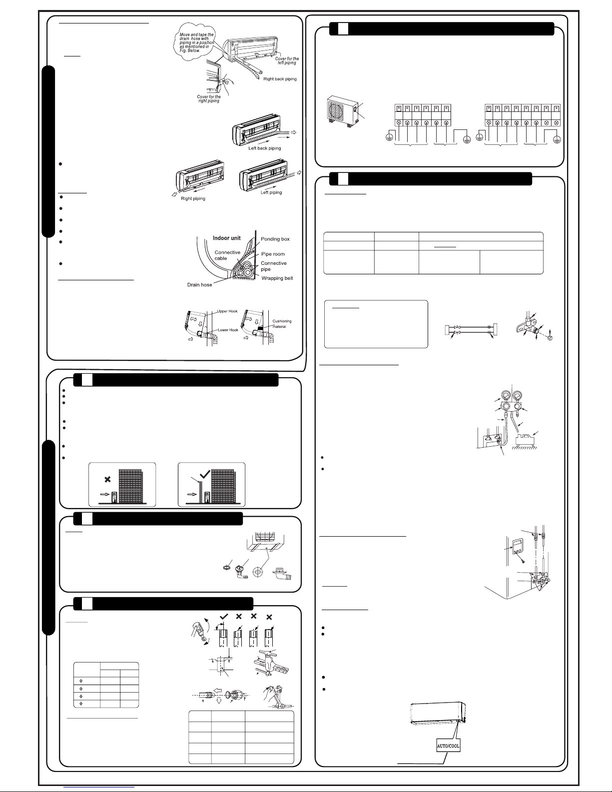
1. Run th e drain h ose slo ping do wnwar d. Take
care NO T to insta ll the drain hos e incorrectl y
as show n in the ‘W RONG’ fig ures illustr ated.
2. When c onnec ting ex tensi on drai n hose,
insul ate the c onnec ting pa rt of ext ensio n
drain h ose wit h a shiel d pipe. D o not all ow
the dra in hose t o be slac k.
Dr ai na ge
RIG HT
WRO NG
20 20 0 01 9 24 8 8 CS 160 I1- BP1 1P ( L) 2 0 13 031 8
Elect ric safet y regulat ions for the init ial insta llati on:
1. If there is seriou s safety prob lem regar ding the powe r supply, the techni cian should refuse to inst all
the air conditi oner unti l the problem is solv ed and explai n the health and safe ty situat ion to the client .
2. Power volt age shoul d be in the range of 90%~110% of rated volta ge.
3. A surge prote ctor or circu it breake r with at least 1.5 times cap acity of maximum curre nt of the
unit should be inst alled at the swit chboa rd.
4. Ensure the air con ditio ner is ground ed (earth ed).
5. Refer to the attac hed Elect rical Con necti on Diagra m located on the pane l of the outdoor unit for
wiring conn ectio ns.
6. All wiring must comp ly with local and nat ional ele ctric al codes and be insta lled by a qualifi ed and
license d electri cian.
7. An all-pole disc onnec tion devi ce which has at least 3mm sep arati on distan ce in all pole and a residual
current dev ice (RCD) wit h the rating of not excee ding 30mA shall be inco rpora ted in the fixed wiri ng
accordi ng to the nationa l rule.
8. An outdoor weath er-pr oof isola tor switc h must be availab le for the instal latio n of this air conditi oner.
El ec tr ic al Work
Cor rect Or ienta tion of
Ins talla tion Pl ate (le vel)
1. Fit th e insta llati on plat e horiz ontal ly on
struc tural p arts of t he wall w ith spa ces
aroun d the Ins talla tion Pl ate.
2. If the w all is ma de of bri ck, con crete o r
the lik e, dril l five to e ight 5m m diame ter
holes i n the wal l. Inse rt clip a nchor
for app ropri ate mou nting s crews .
3. Fit th e insta llati on plat e on the wa ll
with fi ve to eig ht type A screw s.
Mount t he Inst allat ion Pla te and dr ill
holes i n the wal l accor ding to t he wall
struc ture an d corre spond ing mou nting
point s on the in stall ation p late. Th e
Insta llati on Plat e provi ded wit h the
machi ne may di ffer fro m appliance to
appli ance. ( Dimen sions a re in “mm ”
unles s other wise st ated. )
NOT E:
NOT E:
NOT E:
In st al lat i on Plat e Mou nt in g
The mou nting w all mus t be stro ng and so lid
enoug h to prev ent any v ibrat ion.
To protect the f ront panel of th e
indoor u nit during tra nsportatio n,
adhesi ve tapes have be en put on
in the fac tory, as shown in th e
illust ration. Plea se remove all
the tape b efore instal lation.
Mod el A (9K & 12K ): (A:9 00, B:2 90, C:8 3, D:17 0)
Mod el B (18K & 2 1K): (A :1045 , B:305 , C:100 , D:170 )
120mm or
more to wall
120mm or
more to wall
A
A
B
B
1
15.4
1
15.4
115.4
1
15.4
43
43
43
43
C
C
D
D
150mm or more to ceiling
Adhensive tape
150mm or more to ceiling
Left rear side
refrigerant pipe
hole ¦65 mm
Left rear side
refrigerant pipe
hole ¦65 mm
Right rear side
refrigerant pipe
hole ¦65 mm
Right rear side
refrigerant pipe
hole ¦65 mm
Indoor unit outline
Indoor unit outline
120mm or
more to wall
120mm or
more to wall
¦65
Insta ll the ou tdoor u nit on a ri gid bas e to prev ent inc reasi ng nois e level a nd vibr ation .
Place o utdoo r unit on f eet whe n mount ed on the g round s o there i s suffic ient drainag e clearance.
Deter mine th e air out let dir ectio n where t he disc harge d air wil l not be bl ocked . If the in stall ation
locat ion is ex posed t o stron g wind su ch as a sea side, m ake sur e the fan o perat es prop erly by
putti ng the un it leng thwis e along t he wall o r using a d ust or sh ield pl ate.
In part icula rly win dy area , insta ll the un it in suc h a way tha t will pr event t he admi ssion o f wind.
If wall m ounte d insta llati on, the i nstal latio n brack et shou ld acco rd with t echni que req uirem ent
in the in stall ation b racke t diagr am. The in stallation w all should be so lid brick, con crete or the
same in tensi ty cons truct ion. If n ot, app ropri ate act ions to r einfo rce sho uld be ta ken.
The con necti on betw een bra cket an d wall, b racke t and the a ir cond ition er shou ld be fir m,
stabl e and rel iable .
Be sure t here is n o obsta cle whi ch will b lock ra diati ng air.
STR ONG
WIN D
STR ONG
WIN D
Bar rier
Inc orrec t
Cor rect
Seal
Drain jo int
Base pan h ole
of outdo or unit
(A)
(B)
The drai n joint could di ffer slightly, de pendi ng on
differ ent outdoor un it models.
For the d rain jo int wit h the sea l (Fig. A), f irst fi t the sea l onto
the dra in join t, then i nsert t he drai n joint i nto the b ase pan
O
hole of o utdoo r unit, r otate 9 0 to s ecurely asse mble them.
To install dr ain joi nt as sho wn in Fig . B, inse rt the dr ain
joint i nto the b ase pan h ole of ou tdoor u nit unt il it rem ains
fixed w ith a cli cking s ound. F or wate r drain ing off th e outdoor
unit du ring th e heati ng mode , conne ct the dr ain joi nt to an
exten sion dr ain hos e (loca lly pur chase d) if req uired .
2
DRAIN JOINT INSTALLATIO N
OUTDOOR INSALLATION P REC AUTION
3
REFRIGERANT PIPE CONNE CTION
1. Cut co pper tu be with a p ipe cut ter.
2. Put fl are nut s on pipe /tube a fter ha ving
compl eted bu rr remo val, th en flar e the pip e.
3. Firm ly hold t he copp er tube i n the die w ith the
dimen sion sh own in th e table b elow.
.
.
Align p ipes to b e conne cted.
Suffic iently tight en the flare nut w ith fingers,
then ti ghten i t with a sp anner a nd a Torque
Wrench t o the correct to rque setting a s shown.
Exces sive to rque ca n break n ut depe nding
on inst allat ion con ditio ns.
Outer Diam.
(mm)
A (mm)
Max.
Min.
6.35 1.3
0.7
9.52
1.6 1.0
12.7
1.8 1.0
12.7
16
1.8
2.2
1.0
2.0
Bar
Copper Tube
Clamp Handle
Handle
Bar
"A"
Indoor Unit Tubing Flare Nut Pipings
.
Outer
Diameter
Tightening
Torque(N.cm)
Additional Tightening
Torque(N.cm)
¦6.35mm
¦12.7mm
¦16mm
¦9.52mm
1500
(153kgf.cm)
1600
(163kgf.cm)
3500
(357kgf.cm)
4500
(459kgf.cm)
3600
(367kgf.cm)
4700
(479kgf.cm)
2500
(255kgf.cm)
2600
(265kgf.cm)
AIR PURGI NG AND TEST OPERATION
4
5
1. Remove the ele ctric al termin al cover from the out door unit by loos ening the scr ew.
2. Connec t the connect ive cable s to the terminal s identif ied with thei r respect ive match ed number s
on the terminal blo ck of indoor and outd oor units .
3. Secure the cab les onto the term inal with the cor d clamp.
4. To prevent the ing ress of water, form a loop of the connective cab les as illust rated in the installat ion
diagram of indo or and outdoo r units.
5. Insula te unused cor ds (condu ctors ) with PVC-ta pe. Proce ss them so they do not touch any
electri cal or metal part s.
Cover
Screw
Terminal Block of Outdoor Unit
Liquid side: ¦6.35 mm
R410A: (Pipe length-5)x20g/m
20g per meter over 5 meters
(for 9K, 12K & 18K models)
Liquid side: ¦9.52 mm
R410A: (Pipe length-5)x40g/m
40g per meter over 5 meters
(for 21K model)
Connective Pipe Length
Less than 5 meters
More than 5 meters
Air Purging Method
Use Vacuum Pump
Additional Amount of Refrigerant to be Charged
Open th e valve s tem unt il it hit s again st
the sto pper. Do no t try to op en it fur ther.
Tighten t he valve stem ca p securely wit h
a spann er or cre scent .
Valve stem c ap tightenin g torque - see
Tighten ing Torque ta ble.
.
.
.
.
Flare Nut
Stopper
Cap
Valve Body
Valve Stem
Use Vacuum Pump
For all R 410A refr igera nt mode ls, mak e sure th e refri geran t added i nto air c ondit ioner i s in
liqui d form. ( This is d one by tu rn the ch argin g refri geran t cylin der ups ide dow n to char ge.)
Addit ional r efrig erant i s only ad ded aft er the un it has be en vacu umed an d leak te sted.
.
.
.
.
The ind oor uni t and tub ing bet ween th e indoo r and out door un its mus t be evac uated w ith a
vacuu m pump to r emove n on-co ndens ables a nd mois ture fr om the sy stem an d leak te sted.
Check t hat eac h tube (b oth liq uid sid e and gas s ide) be tween t he indo or and ou tdoor u nits
have be en prop erly co nnect ed, fla re nuts t ighte n to the co rrect t orque s ettin gs.
Pipe le ngth an d addit ional a mount o f refri geran t to be cha rged ar e as foll ows:
Outdoor
Unit
Indoor
Unit
Refrigerant
Packed Valve
Flare Nut
Gas side
Liquid side
A
C
D
B
1. Comp letel y tight en the fl are nut s, A, B, C, D.
2. Conn ect the m anifo ld valv e charg e hose (b lue) to t he
servi ce port o f the pac ked val ve on the g as pipe s ide.
3. Conn ect the c harge h ose (ye llow) c onnec tion to t he
vacuu m pump. ( See ill ustra tion on t he righ t.)
4. Full y open th e handl e Lo-si de of the m anifo ld valv e.
5. Oper ate the v acuum p ump to ev acuat e. After st artin g
evacu ation , you can s light ly loos en the fl are nut o f the
packe d valve o n the gas p ipe sid e to chec k that ai r is
enter ing. (Vacu um pump operat ing noise will c hange
and a com pound m eter in dicat es zero i nstea d of minu s)
6. After th e evacu ation i s compl ete, fu lly clo se the ha ndle
Lo-si de of the m anifo ld valv e and sto p the ope ratio n of
the vac uum pum p. But fi rst:
Make ev acuat ion for a t least 1 5 minut es and ch eck
5
that th e compo und met er indi cates - 76cmH g (-1.0 x10 P a).
If a digi tal vac uum gau ge is use d, it sho uld rea d <200 mi crons .
O
7. Turn the s tem of th e packe d valve B a bout 45 cou nter clock wise fo r 6~7 sec onds to r eleas e refri geran t from th e
outdo or into t he syst em, the n tight en the pa cked va lve aga in.
Make su re the pr essur e displ ay in the p ressu re indi cator i s a
littl e highe r than at mosph eric pr essur e.
8. Remo ve the ch arge ho se from t he serv ice por t.
9. Full y open th e packe d valve s tems B an d A.
10. Sec urely t ighte n the cap o f the pac ked val ves (an d servi ce port ).
11. Add additi onal refrige rant in coolin g mode ONLY.
Manifold Valve
Compound Meter
-76cmHg
Handle Lo-Side
Handle Hi-Side
Charge Hose
Charge Hose
Vacuum Pump
Pressure Gauge
Packed Valves
(and Service Port)
Perfo rm test o perat ion aft er comp letin g refri geran t leak ch eck at th e flare n ut conn ectio ns, pac ked
valve s and ser vice po rt and al so afte r elect rical s afety c hecks h ave bee n done.
Check t hat all t ubing a nd wiri ng has be en prop erly co nnect ed.
Check t hat the g as and li quid si de serv ice val ves are f ully op en.
1. Once p ower is c onnec ted, pr ess the O N/OFF b utton o n the rem ote con trol to t urn the u nit on.
2. Use th e MODE bu tton to s elect C OOL, th en HEAT, then AUTO and th en FAN, testing ea ch mode
for sev eral mi nutes t o check t hat all t he func tions w ork wel l.
O
3. When t he room t emper ature i s too low ( lower t han 17 C), t he unit cannot b e controlled b y the
remot e contr ol to run i n cooli ng mode , you nee d to use th e manua l opera tion. M anual o perat ion
is only u sed whe n the rem ote con trol is d isabl ed or tes ts and ma inten ance ar e neces sary.
OneThe man ual con trol bu tton is o n the bot tom of th e unit as s hown in t he illu strat ion bel ow.
press o n the man ual con trol bu tton wi ll lead t o the for ced AUTO ope ration.
If pres sed twi ce with in five s econd s, the un it will o perat e under f orced C OOL opera tion.
4. The tes t operation sh ould take abou t 30 minutes.
Fl ar in g
Ti gh te ni ng Conn e ct io n
1. Vacuu m in g
2. Usin g th e Vac uu m Pum p
4. Test Run n in g
3. Safe ty and Leak ag e Ch ec k
A: Lo pac ked val ve B: Hi pa cked va lve
C and D are e nds of in door un it conn ectio n.
CAUTI ON
1. Soap y water m ethod :
Apply a soa py wate r or a liqu id neut ral det ergen t on the in door an d
outdo or unit f lare nu ts by a sof t brush t o check f or leak age of th e
conne cting p oints ( flare n uts) an d packe d valve s and ser vice po rt.
If bubb les com e out, it i ndica tes tha t there i s a leak.
2. Leak d etect or:
Use an el ectro nic lea k detec tor to ch eck for l eakag e.
O
U
T
D
O
O
R
U
N
I
T
CONNECT THE CABLE TO THE O UTD OOR UNIT
CAUTION
1
Check Points:
Indoor Unit
Flare Nuts
D
B
C
A
Check Points:
Outdoor Unit
Flare Nuts,
Valves and
Service Port
Cover
NOTE:
To Indoor Unit To Indoor Unit
Power Supply Power Supply
Oblique
Roughness
Burr
O
90
1 1
2(N) 2(N)
S S
L LN N
L(1) L(1)
Alway s conne ct the in door un it firs t,
then th e outdo or unit .
Do not al low the p iping t o come ou t from
the bac k of the in door un it.
Be care ful not t o let the d rain ho se beco me
slack .
Heat in sulat ion sho uld be st rappe d to the
exten sion dr ain hos e of indo or unit .
Be sure t hat the d rain ho se is loc ated at
the low est sid e of the bu ndle. L ocati ng at
the upp er side c an caus e the dra in pan to
overf low ins ide the i ndoor u nit.
Never i nter- cross n or inte r-twi st the po wer
wire wi th any ot her wir ing.
1. Pass t he pipi ng thro ugh the h ole in th e wall.
2. Hook t he indo or unit o nto the u pper po rtion
of Inst allat ion Pla te (eng age the i ndoor u nit
with th e upper e dge of th e Insta llati on Plat e).
Ensur e the hoo ks are pr operl y seate d on the
insta llati on plat e by movi ng it in le ft to rig ht.
3. Pipi ng can be e asily a ccomp lishe d by lift ing
the ind oor uni t with a su pport ing cus hioni ng
mater ial bet ween th e indoo r unit an d the wal l.
Then rem ove it after pip ing is finishe d.
4. Pres s the low er left a nd righ t sides o f the
unit ag ainst t he inst allat ion pla te unti l hooks
engag e with th eir slo ts.
CAU TI ON
In do or Unit Ins ta ll at io n
1. For th e left- hand an d right -hand p iping ,
remov e the pip e cover f rom the s ide pan el.
2. For th e right -back a nd left -back p iping ,
insta ll the pi ping as s hown.
NOTE: F or 9K & 12K m odels , there i s only
one-s ide dra inage s truct ure des ign. Fo r 18k
& 21K mod els, on e-sid e drain age str uctur e is
stand ard. Bo th side s drain age str uctur e is
optio nal and c an only b e custo mized f rom
facto ry. For both s ides drainag e structure, i t
can be ch osen fo r right , left or b oth sid es
drain age con necti on. If ch oosin g both si des
drain age con necti on, ano ther dr ain hos e is
neede d as ther e is only o ne drai n hose in clude d
from fa ctory. If ch oosing one sid e drainage
conne ction , make su re the dr ain hol e on the
other s ide is we ll plug ged. The c onnection
of the dr ain hos e shoul d be done b y a
quali fied in stall er to pre vent wa ter lea kage.
3. Bund le the tu bing, c onnec ting ca bles, a nd
drain h ose sec urely a nd even ly with t ape
as show n in illu strat ion on th e right .
Co nn ec ti ve Pipe Inst al la ti on
Becau se the co ndens ed wate r from th e rear
of the in door un it gath ers in po nding b ox
and is pi ped out o f the roo m. Do not p ut
anyth ing els e in the bo x.
I
N
D
O
O
R
U
N
I
T
Mo de l A
Mo de l B
Manual Control Button
 Loading...