

Page 1
Before using your air conditioner, please read
this manual carefully and keep it for future reference.
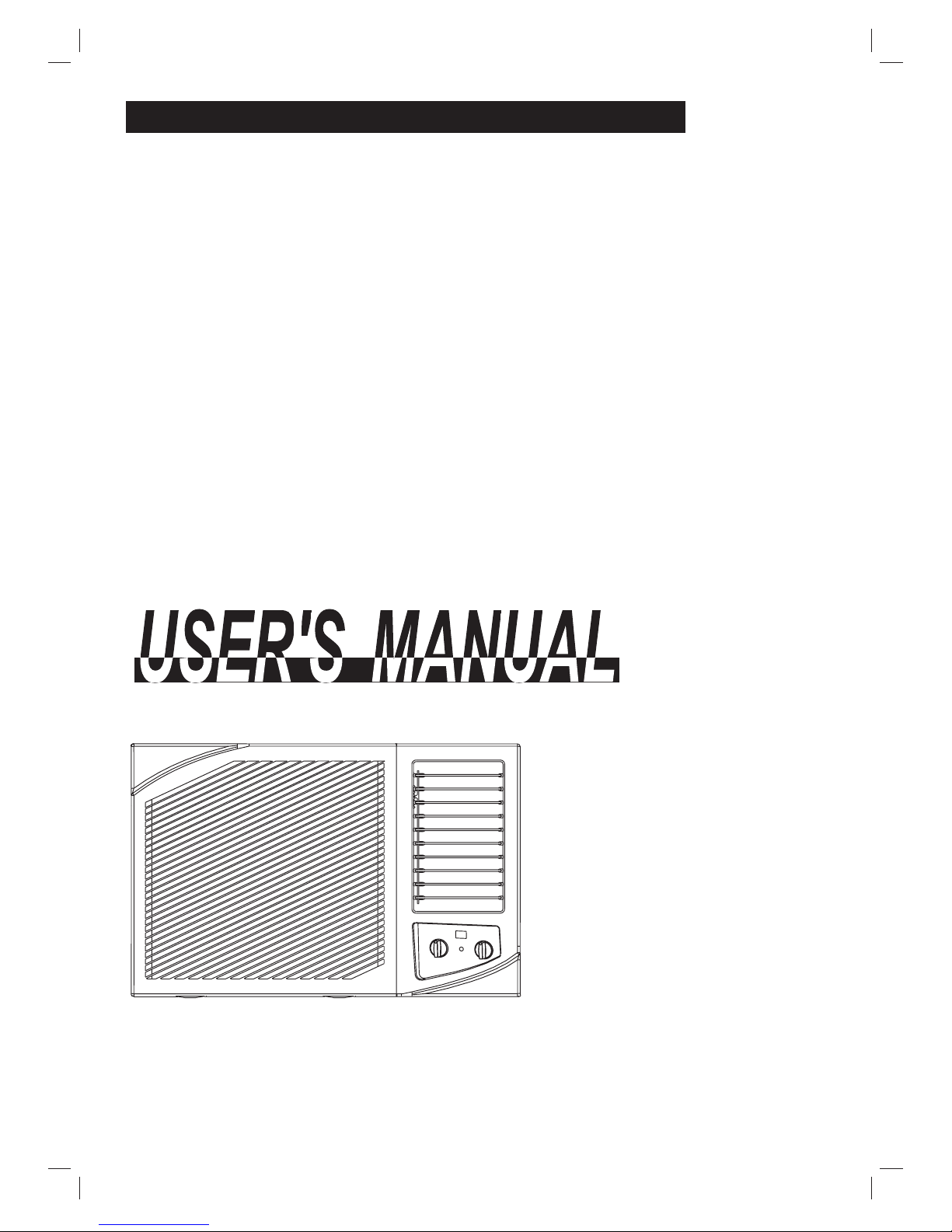
WINDOW/WALL TYPE
ROOM AIR CONDITIONER
-
Prior to installation this air-conditioning unit
must be submitted for approval by the utility
service which provides electricity.
Page 2
1
CONTENTS
1. IMPORTANT SAFETY INSTRUCTIONS.................................................2
2. .............................................3
3. UNIT PARTS IDENTIFICATION ................. .............................................4
4. AIR CONDITIONER FEATURES..............................................................5
5. CARE AND CLEANING ...........................................................................7
6. INSTALLATION.........................................................................................8
7. TROUBLESHOOTING TIPS.................................................................11
8. SPECIFICATIONS ................................................................................12
POINTS FOR USING AIR CONDITIONER
NOTE: This User s Manual provides specific
operating instructions for your model. Use the
room air conditioner only as instructed in this
User s Manual. These instructions are not
meant to cover every possible condition and
situation that may occur. Common sense and
caution must be practiced when installing,
operating, and maintaining any appliance.
Page 3
IMPORTANT SAFETY INSTRUCTIONS
All wiring must comply with local and national electrical codes and be installed
by a qualified electrician.
Never insert your fingers or any foreign objects into the air outlet.
Take special care to warn children of these dangers.
Be sure the air conditioner is properly grounded. To minimize shock and fire
hazards, proper grounding is important. The power cord is equipped with a threeprong grounding plug for protection against shock hazards.
Your air conditioner must be used in a properly grounded wall receptacle. If the
wall receptacle you intend to use is not adequately grounded or protected by a
time delay fuse or circuit breaker, have a qualified electrician install the proper
receptacle. Ensure the receptacle is accessible after the unit installation.
Do not run air conditioner with outside protective cover in place. This could result
in mechanical damage within the air conditioner.
The capacity of the room air conditioner must fit the room size for efficient and
satisfactory operation.
Install the room air conditioner on the shady side of your room.
Do not block air flow inside with blinds, curtains or furniture; or outside with shrubs,
enclosures, or other buildings.
Keep blinds and drapes in other windows closed during the sunniest part of the
day.
Clean the air filter as recommended in the section Care and Cleaning .
Do not use an extension cord or an adapter plug.
WARNING
For your safety
Do not store or use gasoline or other flammable vapors and liquids in the vicinity
of this or any other appliance.
Avoid fire hazard or electric shock. Do not use an extension cord or an adaptor
plug. Do not remove any prong from the power cord.
WARNING
Electrical Information
Energy Saving Ideas
2
Page 4
3
POINTS FOR USING AIR CONDITIONER
NOTE:
To begin operating the air conditioner, follow these steps:
If the air conditioner is turned off, wait 3 minutes before restarting. This
allows pressure inside the compressor and equalize. Failure to follow these
instructions may be harmful to your unit.
1. Set the thermostat to the highest number (coldest or cooler setting).
2. Set the selector control to the highest COOL setting.
3. Adjust the louver for comfortable air flow (see AUTO SWING).
4. Once the room has cooled, adjust the thermostat to the setting you find most
comfortable.
5. Make sure that the air flow inside and outside are not obstructed by anything.
WARNING
To reduce the risk of fire, electric shock, or injury to persons,
read the IMPORTANT SAFETY INSTRUCTIONS before
operating this appliance.
If the unit is operated beyond the conditions specified above, it may cause a failure
of the unit.
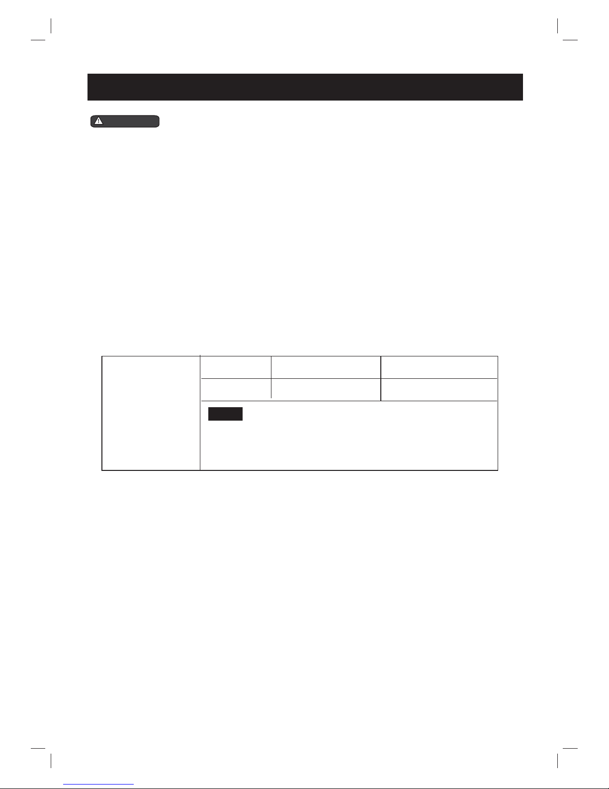
6. This air conditioner is designed to be operated under conditions as follows:
Cooling Operation
Outdoor temp.:
18-43
O
C(T Environment)1
Indoor temp.:
18-32 C
O
(T Environment)
1
Note:
The relative humidity of home should be less
than 80%. If the unit is used in a condition with a
relative humidity over 80%, there will be condensed
water on the appearance of the unit.
21-52OC(T Environment)3
18-32OC(T Environment)3
Page 5
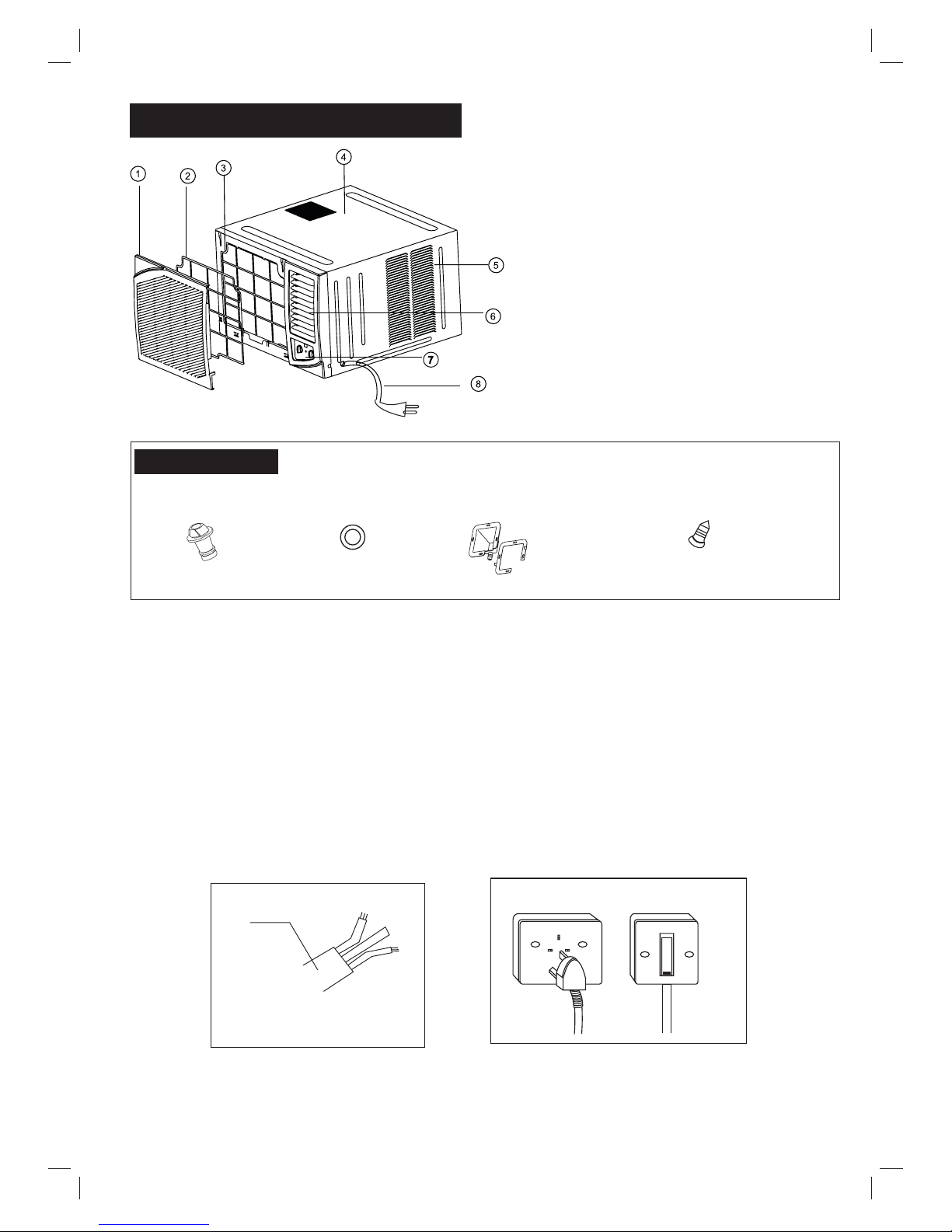
1. Front panel
2. Air filter
3. Frame
4. Cabinet
5. Air inlet grille (outdoor side)
6. Air outlet grille
7. Operation knob
8. Power supply cord and plug
4
UNIT PARTS IDENTIFICATION
ACCESSORIES
1
Screw(Fasten the front panel)
2
Drain Plug(option)
1
Drain Pan (option)
Seal
1
1. Power cord conductors are distinguished according to color as follows (see Fig.1)
2. For your safety and protection, this unit is earthed through the power cord (see Fig.2)
Please contact the manufacturer or its service agent or a similar qualified person if
you want to replace it.
3. Be sure that the unit being correctly grounded. The wall outlet (Air-break switch)should be
provided with reliable earth wire.
4. The unit should be provided with an individual circuit and the circuit breaker/fuse
rating should be the same as that of the power cord and wall outlet.
POWER
CORD
A
E
N
E-Earth wire, yellow/green
N-Neutral wire, blue
A-Active wire, brown
Fig.1
Fig. 2
Wall outlet Air-break switch
Page 6

NOTE: The outline of the operation panel is based on typical model, the function is the
same with your air conditioner while some difference may exist in appearance.
SELECTOR
POWER indicator(some models without): This indicator light remains on when the unit
is on and goes off when the SELECTOR is on OFF position.
AIR CONDITIONER FEATURES
THERMOSTAT
AUTO SWING
SELECTOR
OFF
ON
POWER
COOLER
HIGH
COOL
MED
COOL
LOW
COOL
HIGH
FAN
MED
FAN
LOW
FAN
WAIT THREE MINUTES
BEFORE RESTARTING
OFF
SELECTOR
OFF
HIGH
COOL
MED
COOL
LOW
COOL
HIGH
FAN
MED
FAN
LOW
FAN
The desired cool setting is selected by rotating the knob
to the right to the appropriate location.
has maximum cooling effect and airflow.
has minimum cooling effect and airflow.
has the intermediate cooling effect and
airflow.
will completely shut off the unit.
Rotate the knob to the left to select your choice of fan
speeds for air circulation.
When selecting a fan speed, the compressor will
not run.
The controls featured in this manual are representative
of many available models. Your model may offer slightly
different features.
Cool Mode
LOW
MED
OFF
Fan Mode
Note:
HIGH COOL
COOL
COOL
Note
When turning the SELECTOR knob from "LOW COOL" to "HIGH COOL", keep your speed slow as far
as possible. Do not change the operation mode between "LOW COOL" and "HIGH COOL" too often.
5
THERMOSTAT
SELECTOR
OFF
COOLER
HIGH
COOL
LOW
COOL
HIGH
FAN
LOW
FAN
WAIT THREE MINUTES
BEFORE RESTARTING
OFF
HIGH
COOL
LOW
COOL
HIGH
FAN
LOW
FAN
OFF
HIGH
COOL
MED
COOL
LOW
COOL
HIGH
FAN
LOW
FAN
Page 7

6
THERMOSTAT
THERMOSTAT
COOLER
To set the desired room temperature, rotate the
thermostat switch to the desired setting. After
the set temperature is achieved the thermostat
will automatically start and stop the compressor
in order to maintain the desired set temperature.
Rotate the thermostat selector clockwise for
higher cool settings. Higher cool settings will
provide lower room temperature. Rotate the
thermostat selector counter clockwise for lower
cool settings. Lower cool settings will provide
higher room temperature.
Thermostat
The thermostat is used to set the desired room
temperature when the unit is being operated in
the COOL MODE.
NOTE:
COOLER
During the cooling operation of the unit, when the
thermostat knob is rotated clockwise, allow at least three
minutes before turning back the knob to the
direction. Otherwise the fuse may blow due to an overload
of the unit.
AUTO SWING
OFF
ON
AUTO SWING
Horizontal air flow adjustment (automatically)
When the AUTO SWING switch is turned to ON
position, the vertical louvers automatically oscillate
right and left sweeping the cold air alternately to
obtain comfortable cooling. The vertical louvers may
be stopped at any position when the AUTO SWING
switch is turned OFF .
Page 8

Vertical air flow adjustment (manually)
To adjust vertical air flow direction, adjust any one of
the horizontal louver blades. When turning up or down
the horizontal louver blades, always keep horizontality
the top or bottom blades. This can effectively prevent
water drops condensed on the front panel of the unit.
Vent Control
The vent control is located above the control knobs. The operation method is different
on different models (see the following figures).
For maximum cooling efficiency, CLOSE the vent. This will allow internal air circulation.
OPEN the vent to discharge stale air.
CLOSE VENT OPEN
To open the vent, pull the lever toward you
To close it, push it in.
To open the vent, set the lever to the right position
To close it, set the lever in the left position.
CLOSE OPEN
NOTE: The VENTILATION LEVER should normally be kept in the CLOSED position during
cooling for maximum cooling effect. The "OPEN" position is used only for ventilation.
CARE AND CLEANING
Clean your air conditioner occasionally to keep it looking new. Be sure to unplug
the unit before cleaning to prevent chock or fire hazards.
CAUTION
Air Filter Cleaning
The air filter should be checked at least once a
month to see if cleaning is necessary. Trapped
particles in the filter can build up and cause an
accumulation of frost on the cooling coils.
7
Page 9

Hold the slot under the front panel, then uplift it onwards, and remove the front panel.
Pinch the handle under the air filter and make the air filter arched, remove it from the
underside to upside.
Wash the filter using liquid dishwashing detergent and warm water. Rinse filter thoroughly.
Gently shake excess water from the filter. Be sure the filter is thoroughly dry before
replacing.
Or, instead of washing you may vacuum the filter clean.
Never use hot waterNote:
over 40 C(104 F) to clean the air filter. Never attempt to
operate the unit without the air filter.
CARE AND CLEANING(CONTINUED)
Never use water over 50 C, alcohol, gasoline, acid, solvent or brush to
clean the front panel as this will damage the surface of the part.
NOTE:
If you plan to store the air conditioner during the winter, remove it carefully from the
window according to the installation instructions. Cover it with plastic or return it to
the original carton.
Winter Storage
Never use harsh cleaners, wax or polish on the cabinet front.
Be sure to wring excess water from the cloth before wiping around the controls.
Excess water in or around the controls may cause damage to the air conditioner.
Plug in air conditioner.
Cabinet Cleaning
Be sure to unplug the air conditioner to prevent shock or fire hazard. The cabinet
and front may be dusted with an oil-free cloth or washed with a cloth dampened in
a solution of warm water and mild liquid dishwashing detergent. Rinse thoroughly
and wipe dry.
& Select The Best Location
Install the unit at a place having sufficient strength to support the unit securely.
For maximum efficiency, install the air conditioner on a side of a house or building
which favors more shade than direct sunlight.
Provide sufficient clearance or space around the air inlet and air outlet so that air
flow will not be obstructed, following figures give detailed requirements.
Only trained and qualified service personnel should install, repair or service air
conditioning equipment. Users should not install the air conditioner by themselves.
F
F
F
F
INSTALLATION
8
Page 10

45
O
Scrape
5-10mm
Less than C
more than D
More thanA
More than B
Less than
more thanA
Wall thickness is less than C
If the wall thickness is more than
scrape the wall as shown above.
Make rear side lower so that water will drain
out smoothly.
C
C
Size(mm)
A
B
C
D
400
500
210
60
INSTALLATION(CONTINUED)
The Treatment of Condensed Water
9
To meet different requirement of different type of air
conditioner, there are two kinds of methods for your
choice to treat the condensed water. You can choose
back drainage or non-drainage. See the following
procedures to perform back drainage:
1. Fit the seal onto the drain joint (which provided with
your air conditioner accessory).
2. Remove the rubber plug from the back of the unit.
3. Attach the drain joint to the back of the cabinet
where you remove the plug and rotate 90 to securely
assemble them.
4. Connect the drain joint with a extension drain hose
(Locally purchased)
O
SEAL
DRAIN
JOINT
RUBBER
PLUG
Page 11

10
Installation Steps
Step 1. Remove the front panel and the air filter
1. Hold the slot under the front panel, then uplift it outwards, and remove the front panel
(See Fig.1).
2. Pinch the handle under the air filter and make the air filter arched, remove it from the
slot from underside to upside (See Fig.2).
6
4
5
Step 3. Installation
1. Remove th screws fix the chassis-fixing board and cabinet. some Models have
two more screws on the back of the cabinet. (see Fig.5)
2. Grasp the handle on the chassis and carefully slide the air conditioner out of the
cabinet. (see Fig.6)
3. When need to drain off water, intall the drain plug on the Chassis board. Then fix the
cabinet on the supporter (provide for yourself or contact the dealer)(see Fig.7).
4. Push the unit chassis into the cabinet. (see Fig.8)
5. Fix the chassis and cabinet. (see Fig.5)
e
Step 2. Remove the frame.
Remove the two fixed screws from the frame. (see Fig.3)
Grasp the left corner in the frame's underside, the loosen the frame. (see Fig.4)
1.
2.
Page 12

1. Install the frame. (see Fig.9)
2. Fix the screws on the frame. (see Fig.3)
1. Install the air filter into the frame's slot from
upside to underside. (see Fig.2)
2. Hang the front panel on the frame's buckle,
then press the front panel into the frame's
slot until hear a click. (see Fig.10)
Step 5. Install the front panel and the air filter.
Step 4. Install the frame
Before calling for service, review this list. It may save you time and expense. This list
includes common occurrences that are not the result of defective workman-ship or
materials in this appliance.
Solution
Air conditioner
does not start
Wall plug disconnected. Push plug firmly into wall outlet.
House fuse blown or circuit breaker tripped. Replace fuse with time delay type or
reset circuit breaker.
Selector Control in OFF position. Turn selector to the desired FAN or COOL setting.
TROUBLESHOOTING TIPS
Problem
Air from unit does
not feel cold
enough
Thermostat set too warm. Set thermostat to colder temperature.
Turn selector to a higher COOL position.
Room temperature below 18 C(64 F). Cooling may not occur until room temperature
rises above 18 C(64 F).
Temperature sensing tube touching cold coil, located behind air filter. Straighten
tube away from coil.
Unit turned off by moving thermostat to a higher number and then immediately
turning back to a colder number. Wait approximately 3 minutes. Listen for compressor
to start.
Unit turned off and then on too quickly. Turn unit off and wait 3 minutes before
restarting.
Thermostat set too low. Adjust thermostat to higher number for cooling.
O
O
O
O
Thermostat set too cold for night-time cooling. To defrost the coil, set selector to a
FAN position. Then, set thermostat to a warmer position.
Air filter may be dirty. Clean filter. Refer to Care and Cleaning section. To defrost,
set selector to FAN.
Air conditioner
cooling, but room
is too warm- ice
forming on cooling
coil behind
decorative front.
Outdoor temperature below 18 C(64 F). To defrost the coil, set selector to FAN
position. Then, set thermostat to warmer position.
O
O
11
Page 13

Solution
Problem
Air conditioner turns on
and off rapidly
Noise when unit is
cooling
Water dripping
INSIDE when
unit is cooling.
Improper installation. Tilt air conditioner slightly to the outside to
allow water drainage. Refer to installation instructions - check with
installer.
Dirty air filter- air restricted. Clean air filter.
Air movement sound. This is normal . If too loud, turn selector to
lower FAN setting.
Outside temperature extremely hot. Set to high cool to bring air
past cooling coils more frequently.
Sound of fan hitting water-moisture removal system. This is normal
when humidity is high. Close doors, windows and registers.
Window vibration - poor installation. Refer to installation instructions
or check with installer.
Water dripping
OUTSIDE when
unit is cooling.
Unit removing large quantity of moisture from humid room. This is
normal during excessively humid days.
Dirty air filter- air restricted. Clean air filter. Refer to Care and Cleaning section.
Unit recently turned on in hot room. Allow additional time to remove Stored heat from
walls, ceiling, floor and furniture.
Air conditioner
cooling, but room
is too warm- NO
ice forming on
cooling coil behind
decorative front.
Thermostat set too warm. Turn thermostat clockwise to a colder setting.
Air directional louvers positioned improperly. Position louvers for better air distribution.
Front of units is blocked by drapes, blinds, furniture, etc. - restricts air distribution.
Clear blockage in front of unit.
Doors, windows, registers, etc. Open- cold air escapes. Close doors, windows, registers.
SPECIFICATIONS
12
MODEL(Btu/h)
BODY DIMENSION(mm)
(WxHxD)
<9000
9000<Model<12000
450x345x560
600x380x560
>
18000
661x428x675
661x428x675
12000<Model<18000
Unit dimensions:
Page 14

13
Minimum norminal cross-sectional area of conductors:
Rated current of appliance
(A)
Nominal cross-sectional area
(mm )
2
0.75
1
1.5
2.5
Suggest Minimum Wire Size AWG: :()American Wire Gage
Appliance Amps
AWGWireSize
10
13
18
25
18
16
14
12
30
10
Page 15

CS355-U
2200019053
 Loading...