

Page 1
Instant Electric Water Heater
The diagram above is just for reference. Please take the
appearance of the actual product as the standard.
Instruction Manual
For Model: MWH-38P3
MWH-38P5
MWH-38P3-RS
Thank you very much for purchasing our water heater.
Before installing and operating your water heater, please
read this manual carefully and keep it for future reference.
Page 2

1
TABLE OF CONTENTS
TITLE PAGE
1.Cautions ...........................................................................................................................(2)
2.Product introduction .........................................................................................................(3)
3.Unit installation .................................................................................................................(7)
4.Methods of using ............................................................................................................(10)
5.Maintenance................................................................................................................... (11)
6.Troubleshooting.............................................................................................................. (12)
Sincerely thank you for selecting our electric water heater. Please read this manual carefully
before use; correctly grasp the methods for installation and use of this electrical water heater, to
make full use of its excellent performances. Please do preserve the instruction manual for future
reference.
Page 3
2
This water heater is for household, and it can be installed wherever place that need hot water.
Plug is not used for this water heater; this water heater must be connected directly with power
switch that comes with leakage-protection. Please distinguish live line (red/brown), neutral line
(blue) and earth line (green/yellow) during installation.
Do check whether the amperes of the household wiring enough before installation, and
dedicated circuit must be used when installation.
Before installing this water heater, check and confirm the earth electrode on the socket is reliably
earthed, without electricity.
The hot water from the water heater may cause scald, please test the temperature of the hot
water before use.
The distance between water heater installed and water output should be as nearby as possible
to avoid loss of heat.
The electric water heater may be damaged if the water hardness is too high. To ensure longer
product lifespan, please install and put it into use on condition that the local water hardness is
less than 450mg/L (CaCO3)
In time of lightning/thunder, switch “Off” the Miniature Circuit Breaker (MCB) in advance to
protect the water heater against possible damage.
Inspection on the built-in ELCB (once a month) to avoid a hazard to users such as damage to
property, serious injury or death.
Do cut-off power supply before any maintenance. Any maintenance or adjustment towards this
product by non-professional is highly prohibited.
The damage power cord must be replaced by a good power cord provided by the manufacturer,
and the replacement should be done by a qualified technician or engineer or professionals of
the similar products.
In order to avoid a hazard due to inadvertent resetting of the Earth Leakage Circuit Breaker
(ELCB), this appliance must not be supplied through an external switching device, such as timer
or connected to a circuit that is regularly switched “On” and “Off” by the utility.
Water heater is equipped with adjustable flow capacity safety valve. For safety use, please do
not change its installation location and do not block its water outlet.
For any improper installation and incorrect operation of this product, our company will not be
liable for any responsibility.
This water heater can be used for other purpose, eg. Washing hands, dishes or foods, and so on.
(Multi directional water supply is not available).
When the shower is used by someone such as child, old person, sick person and physical
handicapped person, the concern person is kindly requested to pay attention and check the
shower temperature by using hand from time to time.
The heater must be permanently connected to the electricity supply, direct from the consumer
unit via a double poles linked switch with a minimum contact gap of 3mm in both poles. The
switch must be readily accessible and clearly identifiable and out of reach of person using a fixed
bath or shower. The wiring must be connected to the switch without the use of a plug or socket
outlet.
To prevent personal injury, injury to others and property damage, the instructions below must be
followed. Incorrect operation due to failure to follow instructions will cause harm or damage.
Installation must be carried out by a qualified personnel and in compliance to the local authority
regulations.
WARNING
Special Cautions
The water heater should be earthed before use. Please ensure that the resistance of
household earth wire is <4Ω. Using water heater without earthed is highly prohibited.
!
1. CAUTIONS
●
●
●
●
●
●
●
●
●
●
●
●
●
●
●
●
●
Page 4
3
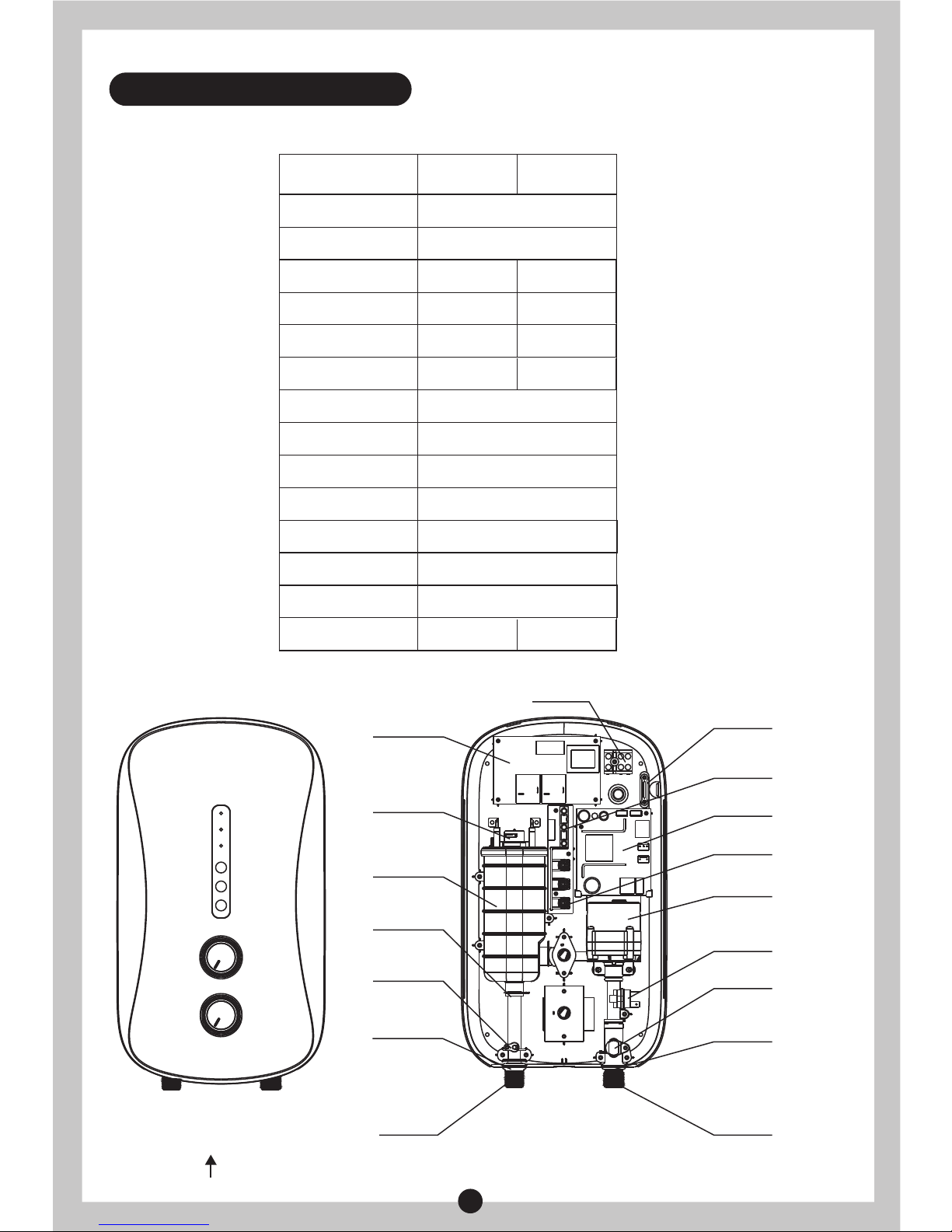
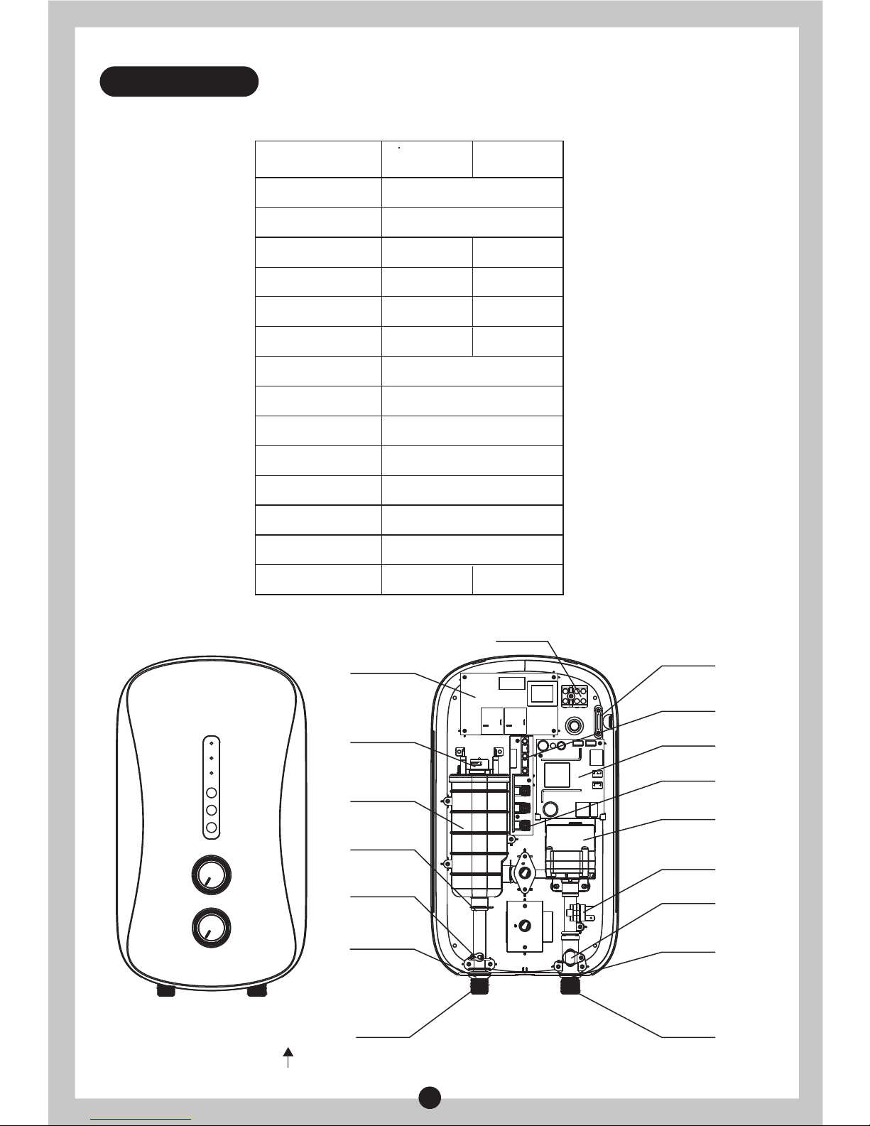
2. PRODUCT INTRODUCTION
2.2 Parts Identification
Terminal block
DC pump board
Indicator light board
Key board
Silicon control
DC pump
Flow sensor
Marker for
water inlet
Water inlet
Wire pressing board
Thermal
cut out
Main control board
Heating
elements
assembly
Stainless
steel circlip
Temperature
sensor
Marker for
wateroutlet
Water outlet
Red Blue
PRODUCT STRUCTURE FOR MWH-38P3 & MWH-38P3-RS
2.1 Technical Performance Parameters
Model
Rated Voltage
Rated Frequency
Rated Power
Rated Current
Dia. Of Wire Code
Air Switch
Rated Pressure
Minimum Flow Rate
Minimum Pressure
Maximum Pressure
Protection Class
Water Proof Class
Products Size
Knob Quantity
MWH-38P3
MWH-38P3-RS
MWH-38P5
3800W
16A
1.5mm²
≥20A
I
240V~
50Hz
0 MPa
2 Liters/minute
0.02 MPa
0.3 MPa
IP25
230×406×102 mm
2
3800W
16A
1.5mm²
≥20A
1
Page 5
4
Main control board
Terminal block
Indicator light board
Key board
Silicon control
Flow sensor
Marker for
water inlet
Water inlet
Wire pressing board
Thermal
cut out
Heating
elements
assembly
Stainless
steel circlip
Temperature
sensor
Marker for
wateroutlet
Water outlet
Red Blue
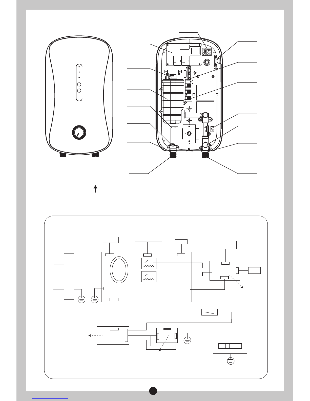
PRODUCT STRUCTURE FOR MWH-38P5
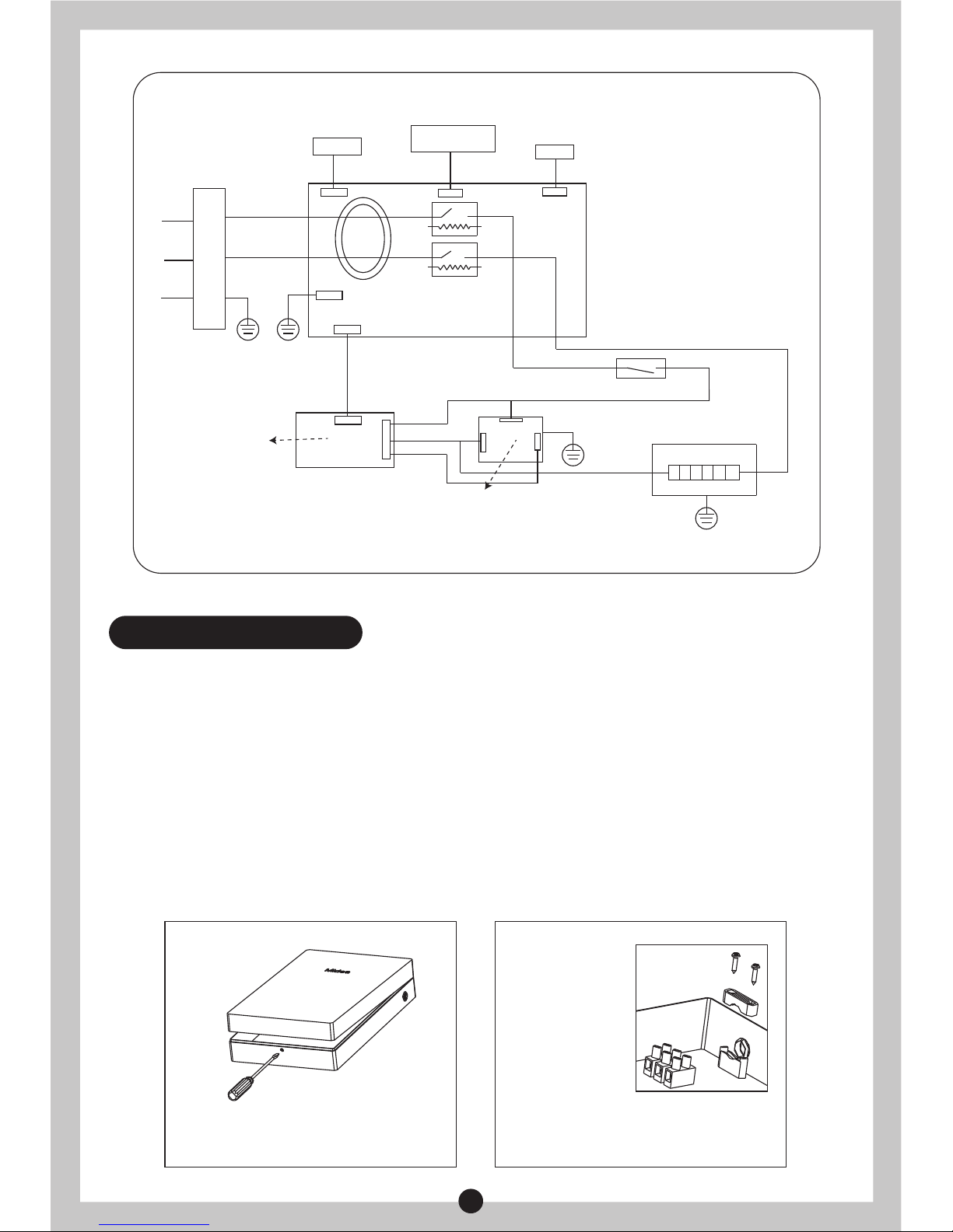
2.4 Internal Wire Diagram
WIRING DIAGRAM FOR MWH-38P3 & MWH-38P3-RS
Indicator Light
And
Key Board
Thermal Cut Out
L
N
E
Red
Blue
Yellow/Green
Temperature
Adjusting Board
Pump Adjusting Board
Heating Elements
Silicon Control
Main Control Board
Relay
Relay
Flow Sensor
Temperature Sensor
Terminal Block
ELCB
CN1
CN3
CN5
CN4
PE
CN2
CN1
CN2
CN1
CN4
CN2
CN3
G
T1
T2
DC Pump Board
DC Pump
Page 6
3.1 Installation Instruction
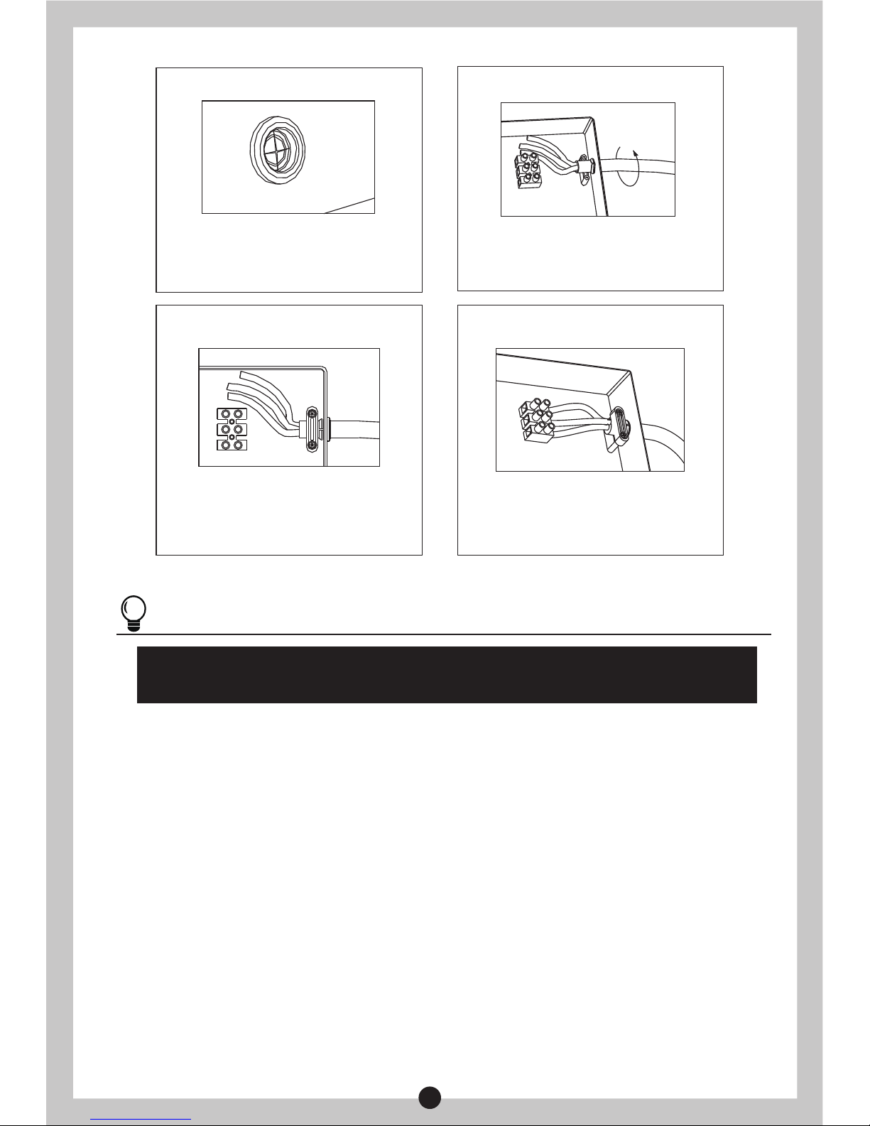
3.2 Power Cord Installation
Check the capacity of power circuit;
Power cord installation;
Water heater installation;
Plumbing connection;
Power supply connection;
①
②
③
④
⑤
Water Supply.
Step 1 Step 2
⑥
3. UNIT INSTALLATION
Remove the screws at the bottom of the unit. Lift
up the Main Switch Knob and Power Knob to
make it free. Remove the front plate gently.
Remove the power cord wire pressing plate and
keep the screws.
5
WIRING DIAGRAM FOR MWH-38P5
Indicator Light
And
Key Board
Thermal Cut Out
L
N
E
Red
Blue
Yellow/Green
Temperature
Adjusting Board
Heating Elements
Silicon Control
Main Control Board
Relay
Relay
Flow Sensor
Temperature Sensor
Terminal Block
ELCB
CN1
CN3
CN5
PE
CN2
CN1
CN2
G
T1
T2
Page 7
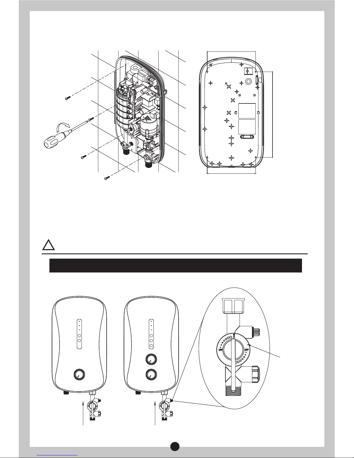
3.3 Water Heater Installation
①
②
③
④
NOTE
The installation position of neutral line (blue), live line (brown/red) and earth line
(green/yellow) should be corresponding to the other end on wiring terminals.
Make sure the distance between the unit and surrounding wall is not less than 300mm, so
that to have enough space for maintenance purpose.
Determine the position of four fixing screws (attached with the unit), make four holes with
corresponding depth in the wall by means of a drill and drive a wall plug into the hole.
Drive in the screws on the top and ensure certain distance between screw head and wall
(See Fig.1)
Determine installation position of the unit according to length of power cord / position
of air switch (Distance between bottom and floor should be ≥1.6m).
Step 3 Step 4
Step 5 Step 6
Gash the middle of the film of the power cord
jacket with a sharp knife in order to put into
power lines.
Tighten the wire-pressing plate with screws to
primary position, ensure that the power cord not
be pulled out more than 60N.
Screw the power cord into the jacket for
installation of wire pressing plate.
Connect the power cord to wiring terminals; the
method is as shown in picture.
6
Page 8
(Fig.2)
Water flow
adjusting
valve with
filter
Cold water inlet
Cold water inlet
3.4 Plumbing Connection
⑤
Mount the unit on the wall and tighten with two screws at bottom, connect the wires and
install top cover with the screws.
①
②
Shower flexible tube should be connected with water outlets and shower head separately,
attached sealing ring should be used at end face.
Water valve with filter should be installed at water inlet of the unit, sealing ring with filter
should be used at end face. (See Fig.2).
(Fig.1)
WARNING
Metallic / chromed hose and conductive control valve shall not be used.
!
7
170
170
300
Page 9
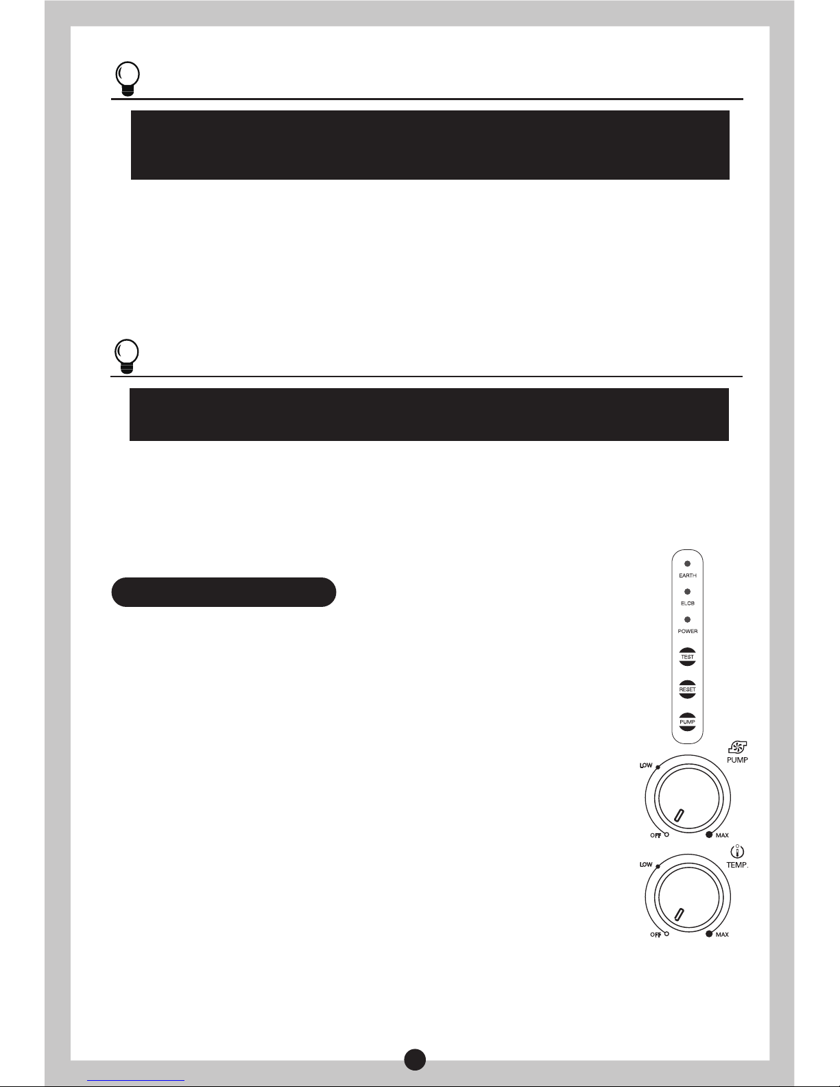
4.1 Operating Of The Unit
4.2 Leakage Testing
4.3 To Adjust Water Flow
Switch on the power supply, the unit will take self-inspection for 2s, “ELCB” green
indicator light will be on (under the condition of no electricity leakage). When the
water flow exceeds 1.2L/min, rotate the knob clockwise to switch on heating
power rotate switch, heating indicator light will be on, the unit start to work.
4. METHODS OF USING
When the water heater is working normally (including working state of PUMP),
press “TEST” button, if the leakage test circuit is no problem, “ELCB” green
indicator light will be off, and the unit will not heat. Press “RESET”, testing will
be canceled, and “ELCB” green indicator light will be on, the unit will be back
to working state set before. If the circuit leaks, press “RESET” button can’t
cancel leakagetesting, “EARTH”、“ELCB” and “POWER” indicator light is
twinkling flicker, it means the water heater has problems and can’t be used; all
the buttons are invalid, heating is stopped, and pump will be closed.
Rotate the handle of water flow adjusting valve to adjust the water flow.
4.4 Electricity Leakage Protection
When the electricity leakage testing circuit is working normally, if the leakage current is bigger
than certain value between 7.5mA and 15mA, “EARTH”、“ELCB” and “POWER” indicator light
will be twinkling flicker, no heating; it can only be used after the failure is excluded. (When
electricity leakage is tested, red and green indicator lights are all off, stop heating and close the
pump system.)
3.5 Power Supply Connection
3.6 Water Supply
①
②
③
Choose air switch with leakage protection according to power of water heater;
When connecting the water heater to electric network, please pay attention to connect live
line (red/brown), neutral line (blue) and earth line (yellow/green) with corresponding line in
electric network.
Adjust power selection knob to“OFF”;
NOTE
Water flow adjusting valve with filter must be used when install the unit. Blue marker
stands for water inlet, red marker stands for water outlet. Do not overexert to avoid
damaging the water heater.
NOTE
A private power cord should be used for this unit. After connecting to electric network,
please check the earth condition and make sure the earth resistance is <4Ω.
After all the plumbing is
finished
connecting, open water inlet valve of the product and supply
water to the unit to drain away air inside until there is stable water flow comes out from shower
head. Check whether there is leakage at joints or not. If there is, check whether the connecting
parts are fastened or not, then re-supply water.
8
Page 10
This electric water heater should be installed at the place without sunshine or rain spray.
Please cut off power supply if not use for long time.
Please blow down the water for about 10 seconds to drain away the impurities in the pipe before
connecting the water source to the electric water heater to avoid blockage of water heater.
If long time no use the unit, check the water heater first before use. Electrify after the water
flows out stably.
Do not spray water to air switch or heater body directly, to avoid moist.
Please cut off the power in the weather of thunder and rain to avoid damaging the water heater.
If not use for long period of time, please cut off water inlet to prolong the lifespan of the water
heater.
Check the power cord connecting terminals frequently to make sure that they are well and
reliably contacted, no overheating phenomenon, and grounding is good or not.
Disassembly shower head and sealing ring with filter to clean periodically.
DECLARATION: this water heater can only be maintained by authorized service personnel,
incorrect installation and using method may cause serious injury or loss of property.
●
●
●
●
●
●
●
●
5. MAINTENANCE
WARNING
Do cut off power supply before maintenance, to avoid danger like electric shock.
!
4.5 To Adjust Water Temperature
Rotate the handle of water flow adjusting valve to adjust to proper water flow. Adjust power by rotating
knob, clockwise rotate, power will be increased and water temperature increase accordingly or vice
versa.
NOTE
For first time using, ensure electrify after the unit is filled fully with water and there is
stable water flow comes out from shower head.
The electric water heater may be damaged if the water hardness is too high. To
guarantee the normal service life, please install and put it into use on condition that the
local water hardness is less than 450mg/L (CaCO3).
The water pressure is increased when Pump is started; Rotate Pump knob to adjust water pressure,
rotate clockwise, water pressure is increased and vice versa.
4.7 To Adjust Water Pressure (For MWH-38P3 & MWH-38P3-RS)
If the water flow is small and power is high while using the unit, outlet water temperature is rather
high; the unit will stop heating automatically. At this time, please lower the power and adjust the
water flow faster in order to avoid inconsistency of water temperature.
4.8 Use After Overheating Protection
9
When the unit is working under normal condition, press “PUMP”, The pump will start immediately and
has been working until the water flow insufficient 1.2L/min for more than 3 seconds.
4.6 To Activate Pump Function (For MWH-38P3 & MWH-38P3-RS)
Page 11
10
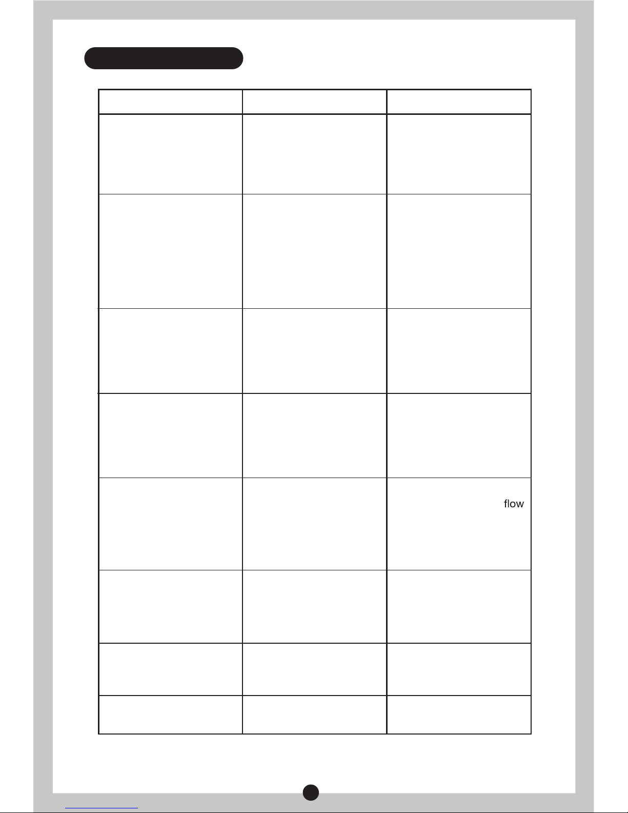
SUGGESTIONS
1. Check whether power
is cut
2. Contact authorized
service personnel for
repair.
1. Rotate “TEMP” knob
2. Repair or replacement
the PCB
1. Press the reset handle
of the thermal cut out
after checking and
troubleshooting
2. Change the heating
elements
3. Adjustable water flow
4. Change the flow sensor
5. Open the flow sensor
and clean the rotor
1. Wait for restoration of
running water supply;
2. Open the inlet valve of
running water.
Adjust the heating power
lower, make the water
bigger.
Contact authorized service
personnel for repair.
Contact authorized service
personnel for repair.
REASONS
1. Power supply error;
2. PCB error;
1. The “TEMP” knob is off;
2.
3. The water flow
insufficient 1.2L/min;
PCB error;
4. Impurities clogging the
flow sensor of the rotor
1. The running water
supply is cut off;
2. The inlet valve of running
water is not open.
1. Water pressure is not
stable.
2. Outlet water temperature
is too high, overheating
protection again and
again.
Electricity leaks.
PUMP error.
Temperture sensor
is broken
Change the temperture
sensor
SYMPTOMS
The heating indicator light
is off and the outlet
water is cold.
The heating indicator light
is on and the outlet
water is cold.
6. TROUBLESHOOTING
Switch on the power
supply, ELCB indicator
light is off.
No water flows out from
the shower head.
Outlet water temperature
sometimes is hot,
sometimes is cold.
Pressure can’t be
increased.
1. The thermal cut out
is cut off
2. Heating elements
is broken
“EARTH”、“ELCB”and
“POWER” indicator light
is twinkling flicker at the
same time
“POWER” indicator light
is twinkling flicker
Page 12

www.midea.com/global
Page 13

Alat Pemanas Air Segera Elektrik
Diagram di atas hanya untuk rujukan. Sila jadikan penampilan produk
yang sebenar sebagai standard.
Panduan Pengguna
Model: MWH-38P3
MWH-38P5
MWH-38P3-RS
Terima kasih kerana telah membeli alat pemanas air Midea.
Sila baca buku panduan ini dengan teliti sebelum pemasangan
dan pengendalian, dan disimpan untuk rujukan kelak.
Page 14

1
KANDUNGAN
Tajuk mukasurat
1.Amaran.............................................................................................................................(2)
2.Pengenalan produk ..........................................................................................................(3)
3.Pemasangan Unit.............................................................................................................(7)
4.Cara-cara penggunaan ..................................................................................................(10)
5.Penyelenggaraan ...........................................................................................................(11)
6.Masalah-masalah dan cara-cara penyelesaian.............................................................. (12)
Terima kasih kerana telah membeli Alat Pemanas Air Midea. Sila baca buku panduan ini dengan
teliti sebelum menggunakan unit ini bagi mengetahui cara-cara pemasangan dan penggunaan
yang betul demi memaksimumkan prestasinya. Simpan buku panduan ini dengan baik-baik
untuk rujukan kelak
Page 15

2
2
Unit ini adalah untuk kegunaan di rumah. Ia sesuai dipasangkan di mana-mana tempat yang
memerlukan air panas.
Unit ini tidak menggunakan palam. Ia mesti disambung terus kepada suis kuasa yang dilengkapi
dengan perlindungan kebocoran. Sila bezakan dawai hidup (merah/perang), dawai neutral (biru) dan
dawai bumi (hijau/kuning) sewaktu pemasangan.
Periksa sama ada ampere pendawaian rumahtangga adalah bersesuaian sebelum pemasangan,
dan pastikan litar rekaan khas digunakan ketika pemasangan.
Sebelum memasang unit ini, periksa dan pastikan elektrod bumi pada soket dibumikan dengan
sempurna dan tidak mengandungi sebarang arus elektrik.
Air panas yang mengalir keluar dari unit ini mungkin mengakibatkan kelecuran, sila periksa suhu air
panas sebelum diguna.
Jarak antara tempat pemasangan unit ini dengan output air hendaklah seberapa dekat yang boleh
bagi mengelakkan kehilangan haba.
Unit ini mungkin akan rosak jika kekerasan air adalah terlalu tinggi. Untuk jangka hayat produk yang
lebih panjang, sila pastikan unit ini dipasang dan digunakan di tempat dengan tahap kekerasan air
tempatan kurang daripada 450mg/L (CaCO3).
Ketika berkilat/berguruh, matikan pemutus litar kenit (MCB) bagi melindungi unit ini daripada
kerosakan yang mungkin timbul.
Periksa ELCB (pemutus litar bocor ke bumi) terbina dalam sekali setiap bulan bagi mengelakkan
kebahayaan terhadap pengguna, seperti kerosakan harta benda, kecederaan serius atau kematian.
Padamkan bekalan elektrik sebelum melakukan sebarang kerja penyelenggaraan. Sebarang kerja
penyelenggaraan atau penyelarasan terhadap unit ini oleh orang yang bukan pakar adalah dilarang
sama sekali.
Kord kuasa yang rosak mesti diganti dengan kord kuasa yang disediakan khas oleh pengilang, dan
kerja penggantian mesti dilakukan oleh juruteknik bertauliah atau jurutera atau pakar dalam produk
yang seumpamanya.
Bagi mengelakkan kebahayaan akibat ELCB (pemutus litar bocor ke bumi) diset semula secara tidak
sengaja, unit ini tidak boleh dibekalkan melalui peranti pertukaran luaran, seperti pemasa atau
disambungkan kepada litar yang kerap “dihidupkan” atau “dimatikan” mengikut kegunaan.
Unit ini dilengkapi dengan injap keselamatan bagi mengawal kapasiti aliran air. Demi keselamatan
penggunaan, jangan sesekali mengubahsuai kedudukan injap atau menutup outlet airnya.
Pihak Syarikat tidak akan menanggung sebarang tanggungjawab ke atas pemasangan atau
pengendalian yang tidak betul.
Unit ini boleh digunakan untuk kegunaan lain seperti membasuh tangan, pinggan mangkuk atau
makanan, dan sebagainya (tidak disediakan bekalan air pelbagai arah.
Apabila unit ini digunakan oleh individu seperti kanak-kanak, warga tua, pesakit atau orang kurang
upaya, penjaga mereka hendaklah memberi perhatian dan memeriksa suhu air mandi dengan
tangan dari masa ke semasa.
Alat pemanas ini mesti disambung kekal pada bekalan elektrik dan secara langsung dari unit
pengguna melalui suis dua kutud dengan jurang sambungan sekurang-kurangnya 3 mm pada
kedua-dua kutud. Suis berkenaan mesti mudah dicapai dan dapat dikenal pasti dengan jelas, serta
berada di luar jangkauan orang yang menggunakan tab mandi atau pancuran tetap. Dawai mesti
disambung pada suis tanpa menggunakan plag atau soket.
Arahan-arahan berikut wajib dipatuhi bagi mengelakkan kecederaan peribadi, kecederaan terhadap orang
lain dan kerosakan harta benda. Pengendalian yang salah akibat tidak mematuhi arahan berikut bakal
menimbulkan kecederaan atau kerosakan. Kerja pemasangan mesti dijalankan oleh pekerja yang
berkelayakan dengan mematuhi peraturan-peraturan yang ditetapkan oleh pihak berkuasa tempatan.
AMARAN
Amaran Khas:
Unit ini mesti dibumikan sebelum penggunaan. Sila pastikan rintangan bagi dawai bumi
kegunaan rumahtangga adalah <4 Ω. Penggunaan alat pemanas air tanpa pembumian
adalah dilarang sama sekali.
!
1.AMARAN
●
●
●
●
●
●
●
●
●
●
●
●
●
●
●
●
●
Page 16

3
2.PENGENALAN PRODUK
2.2 Identikasi bahagian
Blok terminal
Papan pam DC
Papan lampu petunjuk
Papan kekunci
Kawalan Silikon
Pam DC
Sensor aliran air
Tanda untuk
inlet air
Inlet air
Papan Penekan dawai
Pemutus
termal
Papan kawalan utama
Elemen
pemanasan
Klip Lingkaran
keluli tahan karat
Sensor suhu
Tanda untuk
outlet air
Outlet air
Merah
Biru
Struktur Produk untuk MWH-38P3 & MWH-38P3-RS
2.1 Parameter prestasi teknikal
Model
Voltan terkadar
Frekuensi terkadar
Kuasa terkadar
Arus terkadar
Diameter Kod Dawai
Suis Udara
Tekanan Terkadar
Kadar Aliran Minimum
Tekanan Minimum
Tekanan Maksimum
Kelas Perlindungan
Kelas Kalis Air
Saiz Produk
Kuantiti Tombol
MWH-38P3 &
MWH-38P3-RS
MWH-38P5
3800W
16A
1.5mm²
≥20A
I
240V~
50Hz
0 MPa
2 liter/minit
0.02 MPa
0.3 MPa
IP25
230×406×102 mm
2
3800W
16A
1.5mm²
≥20A
1
Page 17

4
Papan Kawalan utama
Blok terminal
Papan lampu petunjuk
Papan kekunci
Kawalan Silikon
Sensor aliran air
Tanda untuk
inlet air
Inlet air
Papan Penekan dawai
Pemutus
termal
Elemen
pemanasan
Sensor suhu
Tanda untuk
outlet air
Outlet air
Merah Biru
PRODUCT STRUCTURE FOR MWH-38P5
2.4 Diagram Pendawaian
Diagram Pendawaian Untuk MWH-38P3 & MWH-38P3-RS
Lampu petunjuk
dan papan kekunci
Pemutus termal
L
N
E
Merah
Biru
Kuning/Hijau
Papan Pelaras
suhu
Papan Pelaras pam
Elemen pemanasan
Kawalan silikon
Papan Kawalan Utama
Relay
Relay
Sensor aliran air
Sensor suhu
Blok Terminal
ELCB
CN1
CN3
CN5
CN4
PE
CN2
CN1
CN2
CN1
CN4
CN2
CN3
G
T1
T2
Papan Pam DC
Pam DC
Klip lingkaran
keluli tahan karat
Page 18

3.1Arahan Pemasangan
3.2 Pemasangan kord kuasa
Periksa kapasiti litar kuasa;
Pemasangan kord kuasa;
Pemasangan alat pemanas air;
Penyambungan sistem paip;
Penyambungan bekalan kuasa;
①
②
③
④
⑤
Bekalan air.
Langkah 1 Langkah 2
⑥
3. PEMASANGAN UNIT
Tanggalkan skru pada bahagian bawah unit
berkenaan. Keluarkan Tombol Suis Utama dan
Tombol Kuasa bagi membuat ia tidak terhalang.
Tanggalkan plat hadapan secara perlahan-lahan.
Tanggalkan papan penekan dawai kord kuasa dan
simpan skru-skru.
5
Diagram Pendawaian Untuk MWH-38P5
Lampu petunjuk dan
papan kekunci
Pemutus termal
L
N
E
Merah
Biru
Kuning/Hijau
Papan Pelaras
suhu
Elemen pemanasan
Kawalan silikon
Papan Kawalan
Utama
Relay
Relay
Sensor aliran air
Sensor suhu
Blok Terminal
ELCB
CN1
CN3
CN5
PE
CN2
CN1
CN2
G
T1
T2
Page 19

3.emasangan alat pemanas air
①
②
③
④
⑤
NOTA
Kedudukan pemasangan dawai neutral (biru), dawai hidup (perang/merah) dan dawai
bumi (hijau/kuning) hendaklah selaras dengan terminal dawai pada hujung yang lain.
Pastikan jarak antara unit dengan dinding di sekeliling tidak kurang daripada 330 mm,
untuk menyediakan ruangan yang mencukupi bagi tujuan penyelenggaraan.
Tetapkan kedudukan bagi keempat-empat batang skru (disertakan bersama unit ini), tebuk
empat lubang yang sedalam palam dinding dengan saiz kepala gerudi yang bersesuian,
masukkan palam dinding ke dalam lubang.
Masukkan skrew di bahagian atas dan pastikan ditinggalkan jarak tertentu antara kepala
skru dengan dinding (rujuk gambarajah 1).
Pasangkan unit ini pada dinding dan ketatkannya dengan dua batang skru di bahagian
bawah, sambungkan dawai dan pasangkan penutup atas dengan skru. Gambarajah 1
Tetapkan tempat pemasangan unit berdasarkan panjang kord kuasa / kedudukan suis
udara (jarak antara bahagian bawah unit dan lantai hendaklah≥1.6 m).
Langkah 3 Langkah 4
Langkah 5 Langkah 6
Hiris lapisan nipis bagi jaket kord kuasa dengan
pisau yang tajam untuk memasukkan dawai
kuasa.
Ketatkan plat penekan dwai dengan skru pada
kedudukan primer, pastikan kord kuasa tidak
ditarik keluar melebihi 60N.
Skru kord kuasa ke dalam jaket untuk memasang
plat penekan dawai.
Sambungkan kord kuasa pada terminal dawai
mengikut cara seperti ditunjukkan dalam
gambarajah.
6
Page 20

(Gambarajah 2)
Injap pelaras
aliran air
dengan
penapis
Inlet air sejuk
Inlet air sejuk
3.4 Penyambungan sistem paip
①
②
Tiub fleksibel pancuran hendaklah disambungkan pada outlet air dan kepala pancuran
secara berasingan, gelang pengedap hendaklah dipasang pada bahagian hujung.
Injap air dengan penapis hendaklah dipasang pada inlet air unit ini, gelang pengedap dengan
penapis hendaklah dipasang pada bahagian hujung. (rujuk gambarajah 2)
(Gambarajah .1)
AMARAN
Hos logam/krom dan injal kawalan konduktif tidak boleh diguna pakai.
!
7
170
170
300
Page 21

4.1 Cara mengendalikan unit ini
4.2 Ujian kebocoran
4.3 Menyelaraskan aliran air
Hidupkan bekalan kuasa, unit ini akan melakukan pemeriksaan kendiri selama 2
saat, lampu petunjuk hijau ELCB akan bernyala (dalam keadaan tidak berlaku
kebocoran elektrik). Apabila aliran air melebihi 1.2L/min, putar tombol mengikut
arah ikut jam untuk hidupkan suis kuasa pemanasan, dengan itu lampu petunjuk
pemanasan akan bernyala dan unit ini mula berfungsi.
4.CARA-CARA PENGGUNAAN
Pada ketika unit ini berfungsi secara normal, tekan butang TEST. Jika ujian
kebocoran menunjukkan litar tiada masalah, lampu petunjuk hijau ELCB akan
padam, dan unit ini tidak akan menjalankan proses pemanasan. Tekan
butang RESET, ujian berkenaan akan dibatalkan dan lampu petunjuk lampu
hijau ELCB akan bernyala, dengan itu unit ini akan kembali berfungsi seperti
tetapan sebelumnya. Jika terdapat kebocoran pada litar, ujian kebocoran
tidak dapat dibatalkan dengan menekan butang RESET, manakala lampu
petunjuk ELCB dan KUASA akan berkelip-kelip. Ini bermakna unit ini ada
masalah dan tidak boleh digunakan; semua butang tidak dapat berfungsi,
proses pemanasan akan berhenti dan pump akan dimatikan.
Putar pemegang injap pelaras aliran air untuk menyelaraskan aliran air
4.4 Perlindungan kebocoran
Pada ketika litar ujian kebocoran elektrik berfungsi secara normal, jika kebocoran arus elektrik
melebihi nilai tertentu antara 7.5mA dan 15mA, lampu petunjuk merah KUASA dan lampu
petunjuk hijau ELCB akan padam, dan tiada proses pemanasan dijalankan. Unit ini hanya boleh
digunakan semula apabila masalah berkenaan telah diselesai (Apabila kebocoran elektrik diuji,
lampu petunjuk ELCB dan KUASA akan berkelip-kelip dan proses pemanasan akan berhenti.)
3.5Penyambungan bekalan kuasa
3.6Bekalan Air
①
②
③
Pilih suis udara dengan perlindungan kebocoran berdasarkan kuasa alat pemanas air.
Apabila menyambung alat pemanas air pada jaringan elektrik, sila memberi perhatian
ketika memasang dawai hidup (merah/perang), dawai neutral (biru) dan dawai bumi
(kuning/hijau) supaya selaras dengan dawai pada jaringan elektrik
Selaraskan tombol pilihan kuasa pada kedudukan “OFF”.
NOTA
Injap pelaras aliran air dengan penapis mesti dipasang apabila memasang unit ini.
Tanda biru untuk inlet air, tanda merah adalah untuk outlet air. Jangan diketatkan secara
berlebihan bagi mengelakkan unit ini daripada mengalami kerosakan.
NOTA
Kord kuasa secara berasingan hendaklah digunakan untuk unit ini. Setelah
disambungkan pada jaringan elektrik, sila periksa keadaan pembumian dan memastikan
rintangan bumi adalah <4Ω
Setelah sistem paip siap disambung, buka injap inlet air pada produk dan bekalan air ke unit ini
untuk membuang keluar udara di dalamnya, sehingga aliran air mengalir keluar dari pancuran
air menjadi mantap. Periksa bahagian penyambung sama ada terdapat sebarang kebocoran.
Jika ia, periksa sama ada alat penyambung diketatkan dengan kemas, kemudiannya
disalurkan air semula
8
Page 22

Unit ini hendaklah dipasang di tempat yang terselindung daripada sinaran matahari atau
percikan air hujan. Sila padamkan bekalan kuasa jika unit ini tidak digunakan untuk
jangkamasa yang panjang.
Sila salurkan air keluar selama 10 saat bagi membuang bendasing di dalam paip sebelum
menyambungkan sumber air kepada unit ini bagi mengelakkan unit ini daripada tersumbat.
Jika unit ini tidak digunakan untuk jangkamasa panjang, sila periksa sebelum penggunaan.
Arus elektrik hanya dihidupkan apabila air mengalir keluar secara mantap.
Jangan menyimbah air pada suis udara atau badan unit ini secara terus bagi mengelakkan ia
menjadi basah.
Putuskan kuasa pada hari hujan berguruh dan berkilat bagi mengelakkan unit ini daripada
kerosakan.
Jika unit ini tidak digunakan untuk jangkamasa panjang, sila putuskan inlet air bagi
memanjangkan jangka hayat unit ini.
Periksa kord kuasa yang bersambungan pada terminal secara kerap bagi memastikan ia
berkeadaan baik dan disambungkan dengan baik, tidak berlakunya kejadian kepanasan
melampau dan sama ada pembumian berkeadaan baik.
Tanggalkan kepala pancuran dan gelang pengedap dengan penapis bagi membersihkannya
secara tetap.
PENGUMUMAN:Unit ini hanya boleh diselenggara oleh juruteknik bertauliah, cara
pemasangan dan penggunaan yang salah mungkin akan mengakibatkan kecederaan atau
kehilangan harta benda yang serius.
●
●
●
●
●
●
●
●
5.PENYELENGGARAAN
4.5 Menyelaraskan suhu air
Putar pemegang injap pelaras aliran air untuk menyelaraskan aliran air yang bersesuaian. Putar
tombol untuk menyelaraskan kuasa. Suhu air akan meningkat apabila tombol diputar mengikut arah
ikut jam, dan sebaliknya.
NOTA
Untuk penggunaan kali pertama, pastikan arus elektrik dihidupkan setelah unit ini diisi
penuh dengan air dan aliran air yang mengalir keluar dari kepala pancuran adalah
mantap.
Unit ini mungkin menjadi rosak jika kekerasan air adalah terlalu tinggi. Bagi memastikan
jangka hayat penggunaan yang normal, unit ini harus dipasang dan digunakan di tempat
yang kekerasan air tempatan tidak melebihi 450 ml/L (CaCO3)
Tekanan air akan meningkat apabila pam dihidupkan; putar tombol Pam bagi menyelaraskan
tekanan air. Jika diputar mengikut arah ikut jam, tekanan air akan meningkat dan sebaliknya.
4.7 Menyelaraskan tekanan air (untuk MWH-38P3 & MWH-38P3-RS)
Jika aliran air menjadi kecil dan kuasanya adalah tinggi apabila unit ini digunakan, suhu air yang
mengalir keluar akan menjadi agak tinggi dan ini akan menyebabkan proses pemanasan berhenti
secara automatik. Jika keadaan ini berlaku, sila rendahkan kuasanya dan mempercepatkan aliran
air bagi mengelakkan masalah suhu air tidak konsisten.
4.8 Penggunaan selepas perlindungan kepanasan melampau
9
Pada ketika unit ini berfungsi secara normal, tekan “PAM”, dengan itu, pam akan mula berfungsi
dengan serta merta, dan berfungsi sehingga aliran air tidak melebihi 1.2L/min untuk masa lebih
daripada 3 saat.
4.6Mengaktifkan fungsi pam (untuk MWH-38P3 & MWH-38P3-RS)
Page 23

AMARAN
Padamkan bekalan kuasa sebelum kerja penyelenggaraan bagi mengelakkan
kebahayaan seperti kejutan elektrik.
!
10
Cara-cara penyelesaian
1. Periksa sama ada kuasa
telah dipadam.
2.Hubungi juruteknik untuk
dibaiki.
1. Putar tombol TEMP.
2. Membaiki atau
menggantikan PCB.
1. Tolak pemegang reset
pemutus termal selepas
diperiksa dan
masalahnya diatasi.
2.Tukar elemen pemanas.
3. Selaraskan aliran air.
4. Tukar sensor aliran air.
5. Buka sensor aliran air
dan bersihkan rotornya.
1.Tunggu sehingga bekalan
air dipulih;
2. Buka injap inlet air bagi
membenarkan air
mengalir masuk.
Selaraskan kuasa
pemanasan yang lebih
rendah dan aliran air
yang lebih besar.
Hubungi juruteknik
untuk dibaiki.
Hubungi juruteknik untuk
dibaiki.
Punca-puncanya
1. Kegagaan bekalan kuasa
elektrik;
2. Kegagalan PCB.
1. Tombol TEMP telah
dipadam;
2.
3. Aliran air tidak melebihi
1.2L/min;
Kegagalan PCB;
4. Rotor sensor aliran air
tersumbat oleh bendasing.
1. Bekalan air tergendala;
2. Injap inlet air tidak dibuka.
1. Tekanan air tidak stabil;
2. Suhu air outlet terlalu
tinggi dan perlindungan
kepanasan melampau
berfungsi secara
berulangan.
Kebocoran elektrik berlaku.
Pam gagal berfungsi.
Sensor suhu sudah rosak. Tukar sensor suhu.
Simptom-simptom
Lampu petunjuk pemanasan
tidak bernyala dan air yang
mengalir keluar adalah sejuk.
Lampu petunjuk pemanasan
bernyala dan air yang
mengalir keluar adalah sejuk.
6. MASALAH-MASALAH DAN CARA-CARA PENYELESAIAN
Apabila bekalan kuasa
dihidupkan, lampu
petunjuk ELCB tidak
bernyala.
Tiada air mengalir
keluar dari kepala.
Suhu air keluar kadang
kala panas dan kadang
kala sejuk.
Tekanan tidak dapat
ditambahkan.
1. Pemutus termal telah
dipadam;
2. Elemen pemanas sudah
rosak.
Lampu petunjuk BUMI,
ELCB dan KUASA
berkelip-kelip pada masa
sama.
Lampu petunjuk KUASA
berkelip-kelip.
Page 24

www.midea.com/global
Produk ini boleh ditukar tanpa sebarang notis.
Sila simpan buku panduan ini dengan baik.
Page 25

以上图片仅供参考,请以实物为准。
安装和使用说明手册
For Model: MWH-38P3
MWH-38P5
MWH-38P3-RS
感谢您购买我们的热水器,安装和使用热水器前请仔细阅读本说明书。
注意:用户需要每月至少检查一次剩余电流装置(电流型漏电
保护装置)是否正常运行。
快热式电热水器
Page 26

1
标题 页数
1.注意事项 ...........................................................................................................................(2)
2.产品介绍 ...........................................................................................................................(3)
3.电器原理图 .......................................................................................................................(4)
4.安装说明 ...........................................................................................................................(5)
5.固定热水器 .......................................................................................................................(6)
6.连接管路 ...........................................................................................................................(7)
7.使用说明 ...........................................................................................................................(8)
8.使用注意事项....................................................................................................................(9)
9.故障及其处理方法........................................................................................................... (10)
由衷地感谢你选用“美的”牌快热式电热器。在使用前请你仔细阅读本说明书,以便充分利用它
的优异性能,请务必保存好此说明书以备将来参考使用。
目 录
Page 27

2
本热水器必须由合资格人士或美的授权的技术人员进行安装和维护,对于非正确安装和使用,或
者不遵守本说明书操作指引,造成的人身或财产损失,我司不承担任何责任。
1. 注意
本热水器适用于家庭使用,可安装于需要即开即用的场所,提供洗澡、洗手、洗菜等生活用热
水。
本热水器不能使用电源插头,必须直接与带漏电保护的空气开关接驳。接线时注意区分火线、
零线与接地线。
安装前必须检查家庭线路容量是否足够,必须使用专用线路安装。
电热水器必须可靠接地。
本电热水器只能在室内且温度不低于0℃的场所安装和使用,如果热水器中的水已结冰,则在化
冰前禁止接通电源。
热水器可能导致烫伤,使用前请用手试好水温。
安装点应尽量靠近用水点,以减少热量在管路中损失。
水质硬度过高易损坏电热水器,为保证正常使用寿命,请在地区水质硬度〈450 mg/L(CaCO3)
条件下安装使用。
雷雨天气请切断电源,以防止雷击损坏电热水器 。
对热水器进行任何维护保养和维修前必须断开电源。非专业人员不得调整和维修热水器。
如果电源线损坏,必须使用制造厂提供的专用电源线,并由制造商、其维修部门或类似部门的
专业人员进行替换。
为避免由热断路器的误复位产生危险,器具不能通过外部开关装置供电,例如定时器或者连接
到由通用部件定时进行通、断电路。
热水器配有流量调节阀,为安全使用,不可擅自更改其安装位置,严禁在热水器出水口安装阀
门。
对于本热水器的非正确安装和使用,我司恕不承担任何责任。
热水器必须可靠地连接到用户家中固定的电路中,严禁使用插头、插座,其连接的固定布线中
必须按布线规则安装一个跳断距离大于3mm的双极断开开关,该开关必须易于操控并且清晰易
见,安装在淋浴者触碰范围之外。
警 告
特别注意事项
电热水器必须可靠接地才能通电使用,且需确保家庭地线接地电阻〈4Ω,严禁在无可靠接
地的情况下使用热水器。
!
1.
2.
3.
4.
5.
6.
7.
8.
9.
10.
11.
12.
13.
14.
15.
Page 28
3
2.2 产品示意图
接线端子
水泵电源板
指示灯板
按键板
可控硅
直流水泵
流量传感器
进水管接头
压线板
主控板
加热元件
温度传感器
出水标记套
进水标记套
蓝色
MWH-38P3 & MWH-38P3-RS产品结构图
2.1 技术参数
型号
额定电压
额定频率
额定功率
额定电流
电源线径
空气开关
额定压力
最小流量
最小工作压力
最大工作压力
电器等级
防水等级
产品尺寸
旋钮数量
MWH-38P3
MWH-38P3-RS
MWH-38P5
3800W
16A
1.5mm²
≥20A
I
240V~
50Hz
0 MPa
2 Liters/minute
0.02 MPa
0.3 MPa
IP25
230×406×102 mm
2
3800W
16A
1.5mm²
≥20A
1
限温器
不锈钢卡簧
红色
出水管接头
2. 产品介绍
Page 29

4
接线端子
指示灯板
按键板
可控硅
流量传感器
进水标记套
进水管接头
压线板
主控板
加热元件
温度传感器
出水标记套
蓝色
MWH-38P5产品结构图
2.3电器原理图
MWH-38P3 & MWH-38P3-RS电器原理图
L
N
E
水泵调节旋钮
Relay
Relay
ELCB
CN1
CN3
CN5
CN4
PE
CN2
CN1
CN2
CN1
CN4
CN2
CN3
G
T1
T2
水泵电源板
直流水泵
指示灯及按键板
限温器
温度调节板
加热元件
可控硅
主控板
流量传感器
温度传感器
红色
蓝色
黄色/绿色
接线端子
限温器
不锈钢卡簧
红色
出水管接头
Page 30

3.1 安装顺序
3.2 安装电源线:(黄/绿线较长端与机器连接)
检查入户线路容量;
安装电源线;
固定热水器;
连接管路;
电源连接;
①
②
③
④
⑤
通水
。
步骤1 步骤2
⑥
拧出固定上下壳螺钉,拆下上壳。
拆下电源线压线板,注意保留安装螺
钉。
5
MWH-38P5电器原理图
指示灯及按键板
限温器
L
N
E
红色
蓝色
黄色/绿色
温度调节板
加热元件
可控硅
Relay
Relay
流量传感器
温度传感器
接线端子
ELCB
CN1
CN3
CN5
PE
CN2
CN1
CN2
G
T1
T2
3. 安装说明
Page 31

3.3 固定热水器
①
②
③
④
⑤
注 意
确定热水器四周到墙壁的距离不小于300mm,以便需要时有空间进行维修。
确定四个固定螺钉(随机附件)位置,用冲击钻(直径6mm)钻4个相应深度的孔,插入塑
料涨管。
拧入上方的螺钉并确保螺钉下端面距离墙壁有一定距离(图.1)。
挂上热水器两个并拧入下方两个固定螺钉,装好内部连接线及上壳,拧上外壳安装螺钉。
参考电源线长度、空气开关位置确定热水器安装位置(下端距离地面 ≥1.6m)。
步骤3 步骤4
步骤5 步骤6
将电源线护套中间薄膜用利刃划开,
以便装入电源线。
用拆下的螺钉将压线板装回原位,确
保电源线不能被小于60N的力拉出。
将电源线旋转拧入护套至适合安装压
线板的位置。
将电源线接入接线端子,安装方法参
考图示。
6
零线(蓝),火线(棕色/红色)和地线(黄绿色)安装位置与接线端子另一端接线相对应。
Page 32

(图.2)
带滤网流量
调节阀
进冷水
进冷水
3.4 连接管路
①
②
花洒软管两端分别连接主机出水口和花洒,出水口端面间加装附送的密封圈。
带滤网流量调节阀安装在主机进水口,进水口端面加装带过滤网密封圈(图2)。
(图.1)
注 意
不得使用金属/镀铬软管和导电性的控制阀。
!
7
170
170
300
Page 33

4.1 运行热水器
4.2 漏电检测
4.3 调节流量
接通电源,先自检测试2秒后,ELCB绿色指示灯亮(在无漏电的前提下),当
水流量略超过1.2L/min时,顺时针旋转接通加热功率旋转开关,加热指示灯亮,
热水器开始工作。
在热水器正常工作时(包括PUMP的工作状态),按下漏电试验键(
TEST),漏电试验电路正常时,ELCB绿色指示灯灭,机器不加热;接着
按下复位键(RESET)可取消漏电试验;如果漏电试验电路不正常时,按
下复位键(RESET)不能取消漏电试验,ELCB绿色指示灯应为常“灭”
状态,代表有故障不能使用热水器,全部按键无效,红色和绿色都不亮,
停止加热关闭水泵系统。
通过旋转带滤网流量调节阀的手柄调节进水流量大小。
4.4 漏电保护
漏电试验电路正常工作时,如果检测到漏电电流大于(7.5mA~15mA)之间的某个值时,
POWER红色和ELCB绿色指示灯灭,不加热;待漏电故障排除后方可使用。(机器上电时,如
果检测到有漏电检测故障,红色和绿色都不亮,停止加热关闭水泵系统)。
3.5 电源连接
3.6 通水
①
②
③
根据热水器功率选择带漏电保护的空气开关。
将电热水器接入电网时,注意确认热水器火线(红色和棕色)、零线(蓝色)和接地线(黄
/绿色)与电网的火线、零线和接地线相对应。
将功率选择旋钮调至OFF档。
注 意
1.安装热水器时必须安装带滤网流量调节阀。
2.蓝色标识为进水口,红色标识为出水口。
3.安装时禁止用力过猛,避免损坏热水器。
注 意
1.热水器必须使用专线供电。
2.热水器接入电网后,检测接地情况并确保接地电阻<4Ω。
所有管路都连接好后,打开热水器进水阀门将热水器通水,排出空气直到花洒有均匀的水喷出,
检查所有连接处是否有漏水,如果有漏水,检查连接处是否未拧紧,然后重新通水。
8
4. 使用说明
Page 34

热水器必须安装在无日晒雨淋的地方,长期不使用时请关闭外接的电源开关。
在将水源接入电热水器之前,请先放水10秒左右,将供水管道内的杂物冲出,以免堵塞电热水
器。
长时间未使用热水器之前,使用前应先进行通水检查,待通畅出水后再通电源使用。
使用时避免将水直接喷洒到空气开关或机身上,以免受潮。
雷雨天气请切断电源,以防止雷击损坏电热水器。
长时间不使用,应关闭进水阀以防热水器长期承压,影响使用寿命。
声明:本热水器仅应由合格的服务人员进行维护保养,不正确的安装和使用方法可能引起严重的
伤害事故或财产损失。
1
2
3
4
5
6
警 告
在打开热水器的外壳对热水器进行维修前,请务必断开电源连接,防止触电等危险出现。
!
4.5 调节水温
通过带滤网流量调节阀调到合适的用水量。通过旋钮调节功率,顺时针转动,功率增大水温升高,
逆时针转动加热功率极减小水温减低。
注 意
1.首次使用必须先注满水,确保花洒有稳定的水流喷出后再通电。
2.水质硬度过高易损坏电热水器,为保证正常使用寿命,请在地区水质硬度〈450mg/L
(CaCO3)条件下使用。
使用过程中,当水流量过小而功率调节得比较大时,出水温度过高时,热水器自动停止加热,此时,
请及时调小加热功率并调大进水流量,以避免水温忽冷忽热的情况。
4.8 超温保护后的使用
9
在水泵启动时, 增加水压。通过调节“PUMP”旋钮调节水压,顺时针转动,水压升高,逆时针转动
水压降低(MWH-38P3 & MWH-38P3-RS产品)。
4.7 调节压力 (仅限于MWH-38P3 & MWH-38P3-RS)
5. 使用注意事项
当“PUMP”旋钮处于开启状态时,按“PUMP”按键,水泵启动工作,如果进水流量小于
1.2L/min,则水泵工作3秒后停止,如果进水流量大于1.2L/min,则水泵继续工作。此按键只是用
于进水流量不足时强行启动水泵,除此之外的状态下,按此键无效。
4.6 水泵的使用 (仅限于MWH-38P3 & MWH-38P3-RS产品)
Page 35

10
1.
2.
1.
2.
1. 1.
2. 2.
故障现象 原因 处理方法
接通电源,ELCB绿色
指示灯不亮
电源故障
电源板故障
检查是否停电
通知维修人员维修
出水忽冷忽热
不能增压
水压不稳定
出水温度过高,
反复超温保护
水压稳定后再使用
调小加热功率,
调大水流量
水泵出现故障
通知维修人员维修
通知维修人员维修
“POWER”指示灯闪烁 温度传感器损坏 通知维修人员维修
“EARTH”、“ELCB”
和 “POWER” 同时闪烁
出现漏电故障
不出水
1.
2.
自来水停水
自来水进水阀未打开
1.
2.
等待自来水供水恢复
打开进水阀
1.
2.
1.
2. 加热器损坏
通知维修人员维修
加热指示灯亮,
并且出水为冷水
3. 3.
4. 4.
1. 1.
2. 2. 通知维修人员维修
“TEMP”旋钮是“off”
加热指示灯不亮,
并且出水为冷水
PCB故障
水流量不足1.2l/min
流量传感器堵塞 打开流量传感器清洁
打开“TEMP”旋钮
待水压升高时使用
限温器故障
检查和排除故障后,
按下限温器复位手柄
6. 故障及其处理方法
Page 36

特别声明:本资料上所有内容均经过认真核对,如有任何印刷错
漏或内容上的误解,本公司保留解释权。
另:产品如有技术改进,会编进新版说明书,恕不另行通知:产
品外观、颜色如有变动,以实物为准。
芜湖美的厨卫电器制造有限公司
地址:安徽省芜湖市经济技术开发区东区万春东路美的工业园
网址:http://www.midea.com 邮政编码:241000
 Loading...