

Midea MWH-38EU3-GR, MWH-38EU5-GR, MWH-38EU3-RS-GR, MWH-38EU5-RS-GR User Manual

Instant Electric Water Heater
Instruction Manual
For Model:
MWH-38EU3-GR
MWH-38EU5-GR
MWH-38EU3-RS-GR
MWH-38EU5-RS-GR
The diagram above is just for reference. Please take the
appearance of the actual product as the standard.
Thank you very much for purchasing our water heater. Before installing and operating your
water heater, please read this manual carefully and keep it for future reference.
The user needs to test the built-in earth leakage circuit breaker(ELCB) at least once a month.

Sincerely thank you for selecting our electric water heater. Please read this manual carefully
before use; correctly grasp the methods for installation and use of this electrical water heater, to
make full use of its excellent performances. Please do preserve the instruction manual for future
reference.
TABLE OF CONTENTS
TITLE PAGE
1.Cautions ...........................................................................................................................(2)
2.Product introduction .........................................................................................................(3)
3.Unit installation .................................................................................................................(7)
4.Methods of using ............................................................................................................(10)
5.Maintenance...................................................................................................................(11)
6.Troubleshooting.............................................................................................................. (12)
1

1. CAUTIONS
To prevent personal injury, injury to others and property damage, the instructions below must be
followed. Incorrect operation due to failure to follow instructions will cause harm or damage.
Special Cautions
●
This water heater is for household, and it can be installed wherever place that need hot water.
●
Plug is not used for this water heater; this water heater must be connected directly with power
switch that comes with leakage-protection. Please distinguish live line (red/brown), neutral line
(blue) and earth line (green/yellow) during installation.
●
Do check whether the amperes of the household wiring enough before installation, and
dedicated circuit must be used when installation.
●
Before installing this water heater, check and confirm the earth electrode on the socket is reliably
earthed, without electricity.
●
The hot water from the water heater may cause scald, please test the temperature of the hot
water before use.
●
The distance between water heater installed and water output should be as nearby as possible
to avoid loss of heat.
●
The electric water heater may be damaged if the water hardness is too high. To ensure longer
product lifespan, please install and put it into use on condition that the local water hardness is
less than 450mg/L (CaCO3)
●
In time of lightning/thunder, switch “Off” the Miniature Circuit Breaker (MCB) in advance to
protect the water heater against possible damage.
●
Inspection on the built-in ELCB (once a month) to avoid a hazard to users such as damage to
property, serious injury or death.
●
Do cut-off power supply before any maintenance. Any maintenance or adjustment towards this
product by non-professional is highly prohibited.
●
The damage power cord must be replaced by a good power cord provided by the manufacturer,
and the replacement should be done by a qualified technician or engineer or professionals of
the similar products.
●
In order to avoid a hazard due to inadvertent resetting of the Earth Leakage Circuit Breaker
(ELCB), this appliance must not be supplied through
or connected to a circuit that is regularly switched “On” and “Off” by the utility.
●
Water heater is equipped with adjustable flow capacity safety valve. For safety use, please do
not change its installation location and do not block its water outlet.
●
For any improper installation and incorrect operation of this product, our company will not be
liable for any responsibility.
●
This water heater can be used for other purpose, eg. Washing hands, dishes or foods, and so on.
(Multi directional water supply is not available).
●
When the shower is used by someone such as child, old person, sick person and physical
handicapped person, the concern person is kindly requested to pay attention and check the
shower temperature by using hand from time to time.
an external switching device, such as timer
!
The water heater should be earthed before use. Please ensure that the resistance of
household earth wire is <4Ω. Using water heater without earthed is highly prohibited.
WARNING
2
2. PRODUCT INTRODUCTION
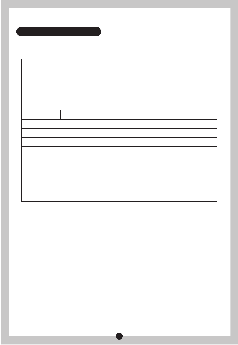
2.1 Technical Performance Parameters
Model
Rated Voltage
Rated Frequency
Rated Power
Rated Current
Dia. Of Wire Core
Air Switch
Rated Pressure
Minimum Flow Rate
Minimum Pressure
Maximum Pressure
Protection Class
Water Proof Class
Products Size
Knob Quantity
MWH-38EU3-GR MWH-38EU3-RS-GR
MWH-3EU5-GR MWH-3EU5-RS-GR
240V~
50Hz
3800W
0~16A
2.5mm²
≥20A
0 MPa
1.5 Liters/minute
0.03 MPa
0.3 MPa
I
IP25
232×406×103 mm
1
3

2.2 Parts Identification
Terminal Block
Thermal
cut out
Tank
Main control board
DC pump
Display board
Temperature
sensor
Water outlet
PRODUCT STRUCTURE FOR
MWH-38EU3-GR MWH-38EU3-RS-GR
Terminal Block
Thermal
cut out
Tank
Temperature
sensor
Silicon control
Flow Sensor
Water inlet
Main control
board
Display board
Silicon control
Flow Sensor
Water outlet
PRODUCT STRUCTURE FOR
MWH-38EU5-GR MWH-38EU5-RS-GR
4
Water inlet

2.3 Internal Wire Diagram
N
PE
2
L
1
3
T1
CN8
N
N
L
RL1RL2
6
T1 G
CN1
CN5
CN2
CN4
CN6
4
CN27CN2
8
T2
T1
G
①:Thermal cut out
②:Terminal Block
③:Heating Elements
④:Flow Switch
⑤:Silicon Control
⑥:Main Control Board
⑦:Display Board
⑧:DC Pump
5
7
WIRING DIAGRAM FOR
MWH-38EU3-GR MWH-38EU3-RS-GR
T1
CN8
2
L
N
PE
RL1RL2
N
N
L
①:Thermal cut out
6
T1 G
CN1
CN5
1
3
CN4
CN6
4
T2
T1
G
②:Terminal Block
③:Heating Elements
④:Flow Switch
⑤:Silicon Control
⑥:Main Control Board
⑦:Display Board
5
7
WIRING DIAGRAM FOR
MWH-38EU5-GR MWH-38EU5-RS-GR
5
3. UNIT INSTALLATION
3.1 Installation Instruction
Check the capacity of power circuit;
①
Power cord installation;
②
③
Water heater installation;
④
Plumbing connection;
⑤
Power supply connection;
Water Supply.
⑥
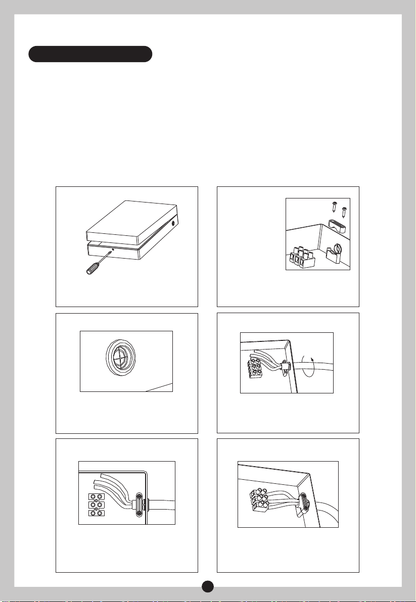
3.2 Power Cord Installation
Step 1 Step 2
Remove the screws at the bottom of the unit. Lift
up the Main Switch Knob and Power Knob to
make it free. Remove the front plate gently.
Remove the power cord wire pressing plate and
keep the screws.
Step 3 Step 4
Gash the middle of the film of the power cord
jacket with a sharp knife in order to put into
power lines.
Screw the power cord into the jacket for
installation of wire pressing plate.
Step 5 Step 6
Tighten the wire-pressing plate with screws to
primary position, ensure that the power cord not
be pulled out more than 60N.
Connect the power cord to wiring terminals; the
method is as shown in picture.
6

NOTE
The installation position of neutral line (blue), live line (brown/red) and earth line
(green/yellow) should be corresponding to the other end on wiring terminals.
3.3 Water Heater Installation
Determine installation position of the unit according to length of power cord / position
①
of air switch (Distance between bottom and floor should be ≥1.6m).
Make sure the distance between the unit and surrounding wall is not less than 300mm, so
②
that to have enough space for maintenance purpose.
Determine the position of four fixing screws (attached with the unit), make four holes with
③
corresponding depth in the wall by means of a drill and drive a wall plug into the hole.
④
Drive in the screws on the top and ensure certain distance between screw head and wall
(See Fig.1)
⑤
Mount the unit on the wall and tighten with two screws at bottom, connect the wires and
install top cover with the screws.
10
295
150
3.4 Plumbing Connection
Water valve with filter should be installed at water inlet of the unit, sealing ring with filter
①
should be used at end face. (See Fig.2).
Shower flexible tube should be connected with water outlets and shower head separately,
②
attached sealing ring should be used at end face.
!
Metallic / chromed hose and conductive control valve shall not be used.
WARNING
7
(Fig.1)
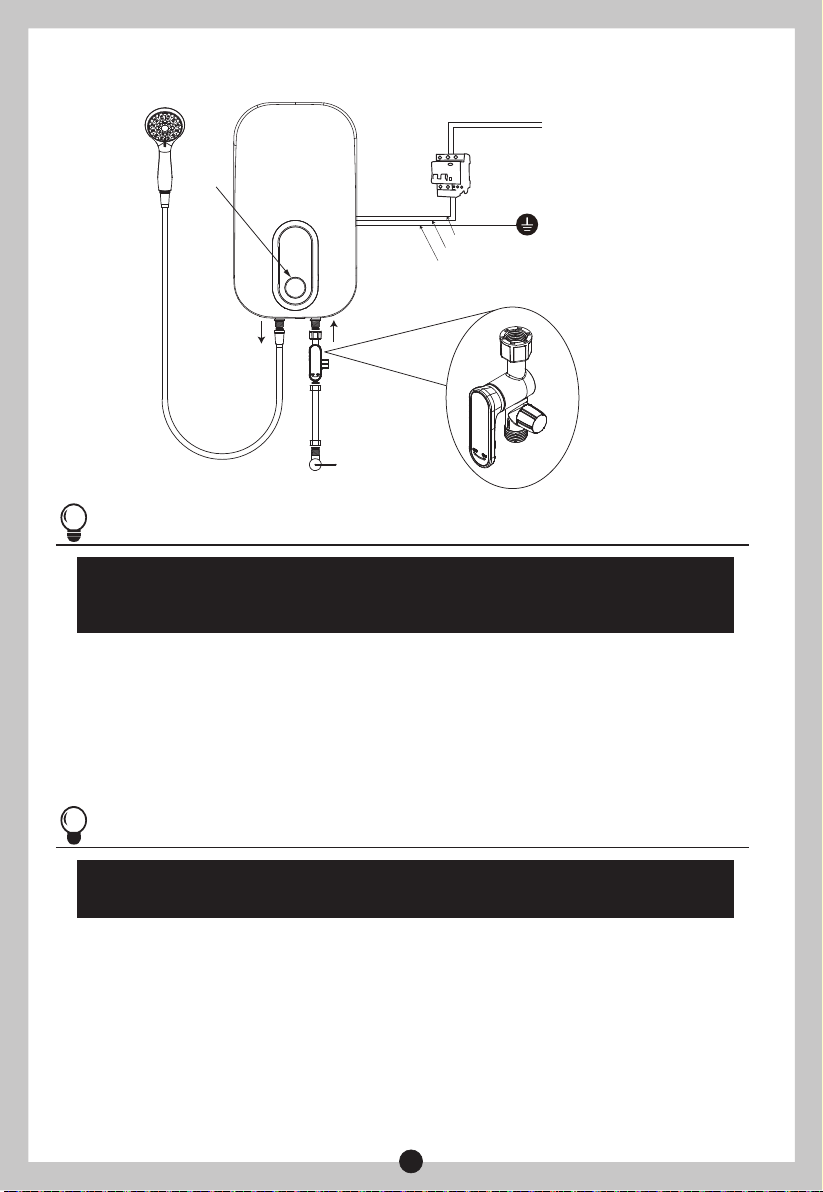
Power
knob
Outlet Inlet
To main line
wire
L(Red)
N(Blue)
E(Yellow/Green)
Circuit
breaker
Valve
Valve
Water flow
adjusting
valve with
filter
(Fig.2)
NOTE
Water flow adjusting valve with filter must be used when install the unit. Blue marker
stands for water inlet, red marker stands for water outlet. Do not overexert to avoid
damaging the water heater.
3.5 Power Supply Connection
Adjust power selection knob to“OFF”;
①
Choose air switch with leakage protection according to power of water heater;
②
When connecting the water heater to electric network, please pay attention to connect live
③
line (red/brown), neutral line (blue) and earth line (yellow/green) with corresponding line in
electric network.
NOTE
A private power cord should be used for this unit. After connecting to electric network,
please check the earth condition and make sure the earth resistance is <4Ω.
3.6 Water Supply
After all the plumbing is finished connecting, open water inlet valve of the product and supply
water to the unit to drain away air inside until there is stable water flow comes out from shower
head. Check whether there is leakage at joints or not. If there is, check whether the connecting
parts are fastened or not, then re-supply water.
8
 Loading...