

Page 1
Window Air Conditioner
MAW
Capacity: 10000BTU/h
en
USER MANUAL
Warning notices: Before using
this product, please read this
manual carefully and keep it for
future reference. For additional
support, please call customer
service at 1-866-646-4332.
The design and specifications are
subject to change without prior
notice for product improvement.
Consult with your dealer or
the manufacturer for details.
version E - 09 - 2020 (PREVIEW06)
version B - 02 - 2020
MW10MSWBA4RCM
midea.com
Page 2
Owner’s Manual
SAFETY PRECAUTIONS ............................................................................. 3
OPERATING INSTRUCTIONS .................................................................... 8
INSTALLATION INSTRUCTIONS .............................................................. 13
CARE AND CLEANING ............................................................................. 25
TROUBLESHOOTING TIPS ...................................................................... 26
REMOTE CONTROL AND APP INSTRUCTIONS ..................................28
WARRANTY ................................................................................................ 35
Read This Manual
Inside you’ll find many helpful hints on how to use and maintain your air conditioner
properly. Just a little preventive care on your part can save you a great deal of time
and money over the life of your air conditioner. You’ll find many answers to common
problems in the troubleshooting tips - you should be able to fix most of them quickly
before calling service. These instructions may not cover every possible condition of
use, so common sense and attention to safety is required when installing, operating
and maintaining this product.
CAUTION
• For support, please call the Service Center at 1-866-646-4332.
• This appliance is not intended for use by people (including children) with reduced
physical, sensory, or mental capabilities or lack of experience and knowledge,
unless they have been given supervision or instruction concerning use of the
appliance by a person responsible for their safety.
• Children should be supervised to ensure that they do not play with the appliance.
• The appliance shall be installed in accordance with national wiring regulations.
• Do not operate your air conditioner in a humid room such as a bathroom or laundry
room.
Page 2
Page 3
SAFETY PRECAUTIONS
To prevent injury to the user or other people and property damage, the instructions
shown here must be followed. Incorrect operation due to ignoring of instructions may
cause harm or damage. The level of risk is shown by the following indications.
Precautions
Safety
WARNING
CAUTION
NOTICE
This symbol indicates a hazardous situation which, if not
avoided, could result in death or serious injury.
This symbol indicates a hazardous situation, which, if not
avoided, could result in minor or moderate injury.
This symbol addresses practices not related to physical
injury.
WARNING
• Be sure the air conditioner has been securely and correctly installed according to
the installation instructions in this manual. Save this manual for possible future use
in removing or installing this unit.
• Plug in power cord plug properly.
Otherwise, it may cause electric shock or fire due to excess heat generation.
• Do not modify power cord length or share the outlet with other appliances as it
may cause electric shock or fire due to overheating.
• Always ensure effective grounding.
Incorrect grounding may cause electric shock.
• Unplug the unit if you notice unusual sounds or smells or smoke coming from it.
A damaged product may cause fire and electric shock.
• Ventilate room before operating the air conditioner if there is a gas leakage from
another appliance.
• Do not operate or stop the unit by inserting or pulling out the power cord plug.
• Do not operate with wet hands or in very humid environments.
It may cause electric shock.
• Do not allow water to come into contact with any electric parts.
It may cause failure or electric shock.
• Do not use the socket if it is loose or damaged.
It may cause fire and electric shock.
• Do not use or keep the power cord close to heating appliances.
It may cause fire and electric shock.
• Do not use any devices or materials for installation that are not recommended in
this manual.
Page 3
Page 4
Precautions
Safety
WARNING
• Do not disassemble or modify unit.
It may cause failure and electric shock.
• Do not damage or use an alternate power cord.
It may cause fire and electric shock.
If the power cord is damaged, it must be replaced by the manufacturer or an
authorized service center or a similarly qualified person in order to avoid a hazard.
• Do not direct airflow straight into persons to avoid possible health hazard.
• Do not open the unit during operation.
It may cause electric shock.
• Do not use the power cord near flammable gas or combustibles, such as gasoline,
benzene, thinner, etc.
It may cause an explosion or fire.
• Do not let children hang on the air conditioner or bracket.
A serious injury may occur.
• Avoid fire hazard or electric shock. Do not use an extension cord or an adaptor
plug. Do not remove any prongs from the power cord.
• Be sure the air conditioner is properly grounded. To minimize shock and fire
hazards, proper grounding is important. The power cord is equipped with a
three-prong grounding plug for protection against shock hazards.
• Your air conditioner must be used in a properly grounded wall receptacle. If the
wall receptacle you intend to use is not adequately grounded or protected by a
time delay fuse or circuit breaker, have a qualified electrician install the proper
receptacle. Ensure the receptacle is accessible after the unit installation.
• Be sure the electrical service is adequate for the model you have chosen. This
information can be found on the serial plate, which is located on the side of the
cabinet and behind the grille.
• Do not drink the drain water. It may contain mold and bacteria that can lead to
death if ingested.
CAUTION
• When the air filter is to be removed, do not touch the metal parts of the unit.
It may cause injury.
• When the unit needs cleaning, switch off, and turn off the circuit breaker.
Do not clean unit when power is on as it may cause fire, electric shock or injury.
• Do not place obstacles around air inlets or inside of air outlet.
It may cause failure or accident.
• Clean with a soft cloth only. Do not use strong detergents that contain wax or
thinners as it may damage the product.
• Use caution when unpacking and installing. Sharp edges could cause injury.
Page 4
Page 5

CAUTION
• Do not clean the air conditioner with water.
Water may enter the unit and degrade the insulation which could lead to
electric shock.
• Do not put a pet or house plant where it will be exposed to direct air flow.
This could injure the pet or harm the plant.
• Hold the plug by the head of the power plug when taking it out.
Otherwise, it may cause electric shock and damage.
• Ensure that the installation is properly secured to prevent the product from
potentially falling.
• Do not place heavy objects on the power cord and ensure that the cord is not
compressed.
Otherwise, there is danger of fire or electric shock.
• If water is spilled on the unit, turn off the unit and switch off the circuit breaker.
Isolate supply by taking the power-plug out and contact a qualified service
technician.
• Do not use near gas stove or other gas burning appliances, as air flow may affect
gas combustion.
• Do not use for any purpose other than room comfort.
Do not use this air conditioner to preserve precision devices, food, pets, plants,
and art objects. It may cause deterioration.
• Turn off the main power switch if the unit is not to be used for an extended time.
• Always insert the filters securely. Clean filter once every two weeks.
Operation without filters may cause failure.
Precautions
Safety
Page 5
Page 6
Precautions
Safety
Operation of Current Device
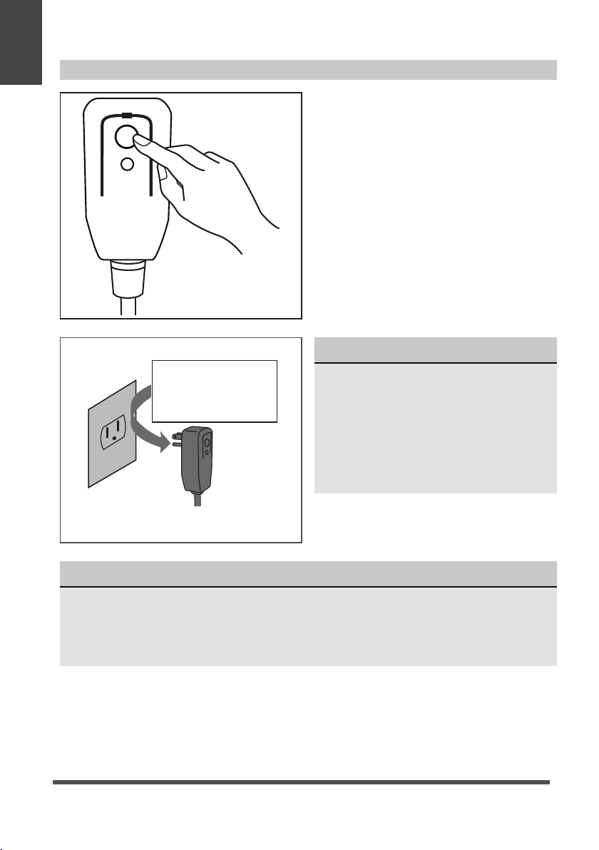
Plug in &
press RESET
RESET
TEST
Grounding type wall receptacle
Do not, under any
circumstances, cut,
remove or bypass
the grounding prong.
The power supply cord contains a current
measuring device that detects damage to
the power cord. Test your power supply
cord as follows:
1. Plug in the air conditioner.
2. The power supply cord will have TWO
buttons on the plug head. Press the
TEST button. You will notice a click as
the RESET button pops out.
3. Press the RESET Button. You will
notice a click as the button engages.
4. The power supply cord is now
supplying electricity to the unit. (On
some products this is also indicated
by a light on the plug head.)
NOTICE
The power supply cord with this
air conditioner contains a current
detection device designed to reduce
the risk of fire.
In the event that the power supply
cord is damaged, it can not be
repaired. It must be replaced with a
cord from the manufacturer.
Power supply cord with 3-prong grounding
plug and current detection device.
NOTICE
• Do not use this device to turn the unit on or off.
• Always make sure the RESET button is pushed in for correct operation.
• The power supply cord must be replaced if it fails to reset when either the TEST
button is pushed, or it can not be reset. Please contact Customer Service.
Page 6
Page 7
Precautions
Safety
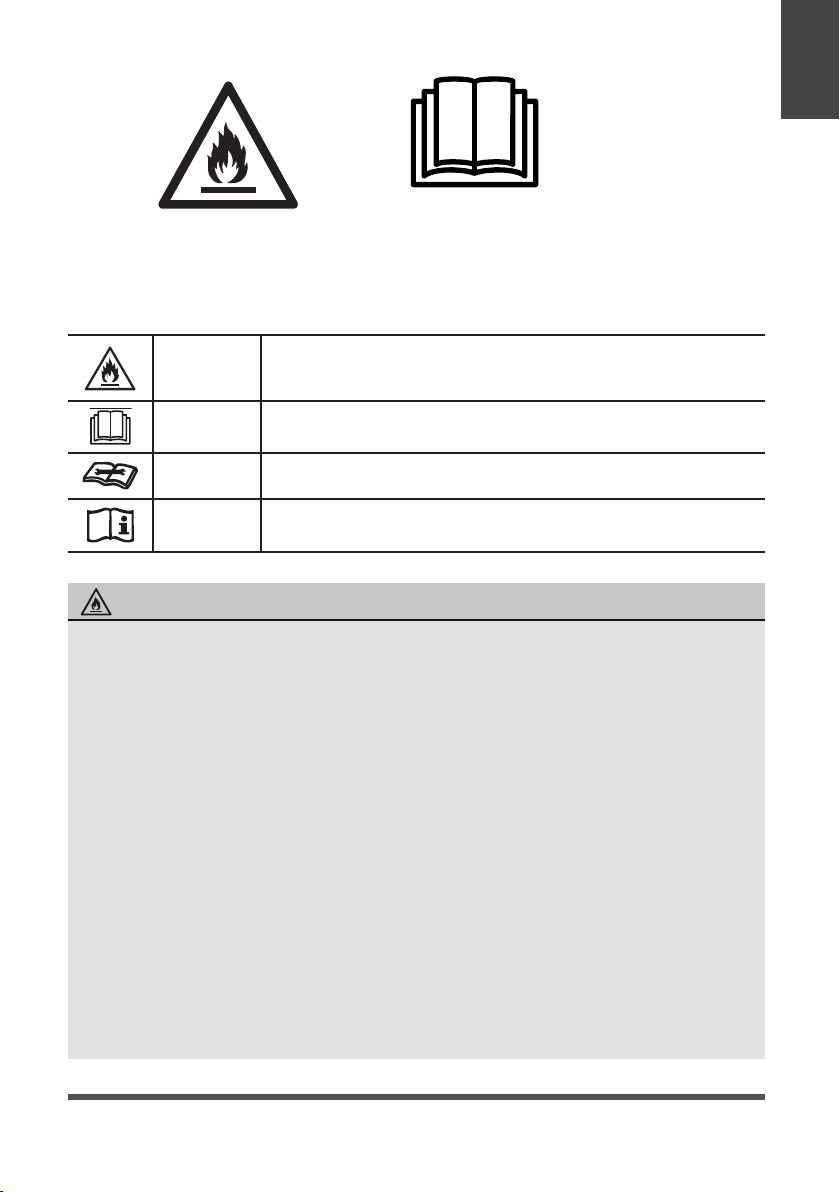
Ca ution: Ris k of fire /
flammable ma terials
(Required fo r R32/R 290 units on ly)
IMPORTANT NOTE :Read t his manual
carefully be fore installing o r operating
your new air con ditio ning unit. M ake sure
to s ave this man ual for future refe rence.
EXPLANATION OF SYMBOLS DISPLAYED ON THE UNIT
WARNING
CAUTION
CAUTION
CAUTION
This symbol shows that this appliance used a flammable
refrigerant. If the refrigerant is leaked and exposed to an
external ignition source, there is a risk of fire.
This symbol shows that the operation manual should be read
carefully.
This symbol shows that a service personnel should be handling
this equipment with reference to the installation manual.
This symbol shows that information is available such as the
operating manual or installation manual.
WARNING
• Do not try to accelerate the defrosting process or methods of cleaning that are
not recommended by the manufacturer.
• The appliance shall be stored in a room without a continuously operating ignition
source (for example, open flames or an operating gas appliance) or an ignition
source (for example, an operating electric heater) close to the appliance. The
appliance shall also be stored in a room without ignition sources.
• Do not pierce or burn.
• Be aware that the refrigerants may not contain an odor.
• Keep ventilation openings clear of obstruction.
• Unit is only to be serviced by a Midea authorized servicer, please call Customer
Service at 1-866-646-4332 for support.
• Flammable refrigerant R32 is used within air conditioner. Please follow the
instructions carefully to handle, install, clean, and service the air conditioner
to avoid damage or hazard. Do not dispose of air conditioner in regular trash.
Contact qualified agency for proper disposal.
• No open fire or devices that generate spark/arcing shall be around the air
conditioner to avoid causing ignition of the flammable refrigerant used. Please
follow the instructions carefully to store or maintain the air conditioner to
prevent mechanical damage from occurring.
Page 7
Page 8

OPERATING INSTRUCTIONS
Normal Sounds
High Pitched Chatter
Instructions
Operating
Vibration
Unit may vibrate and
Trickling Sound
Sound Performance
The following table shows the sound performance data for these window air conditioners.
Please use your specific model number to reference the correct sound power number
in the table.
Sound of Rushing Air
In front of the unit, you
may hear the sound of
rushing air being moved
by the fan.
Gurgle/Hiss
noises may be heard
Model Number Sound Power, dB(A)*
MW12MSWBA4RCM 42
* per ISO 3744 at low fan speed
NOTICE
All the illustrations in this manual are for explanation purpose only. The actual
installation may vary.
Page 8
Page 9

Air Conditioner Operation
WARNING
To reduce the risk of fire, electrical shock, or injury to people or property, read the
SAFETY PRECAUTIONS before operating this appliance.
Cooling Operation
Outdoor temp.: 18°C ~ 43°C / 64°F ~ 109°F
Indoor temp.: 16°C ~ 32°C / 60°F ~ 90°F
NOTICE
• The relative humidity of the room should be less than 80%. If the unit is used in a condition
with a relative humidity over 80%, there will be condensed water on the surface of the unit.
• Performance may be reduced outside of these operating temperatures.
NOTICE
Always wait 3 minutes when turning the unit off and then on again, or when changing from
cool to fan and back to cool. This prevents damage from occurring to the compressor.
To begin operating the air conditioner, follow these steps:
1. Plug in the air conditioner (be sure to follow the power cord instructions).
2. Turn the power on to the air conditioner, using the ON/OFF button.
3. Set the thermostat to the coldest temperature setting.
4. Select the Cool mode setting.
5. Adjust the louver for comfortable air flow (see Air Directional Louvers).
6. Once the room has cooled, adjust the thermostat to the setting you find most comfortable.
7. Make sure the air flow inside and outside is not obstructed by anything.
Air Directional Louvers
The louvers will allow you to direct the air
flow up or down (on some models) and left
or right throughout the room as needed.
Use the SWING button until the desired
up/down direction is obtained.
Move the louvers from side to side until the
desired left/right direction is obtained.
Use SWING button for up/down direction
Instructions
Operating
Adjust louvers for left/right direction
Air Direction
Page 9
Page 10
Air Conditioner Features
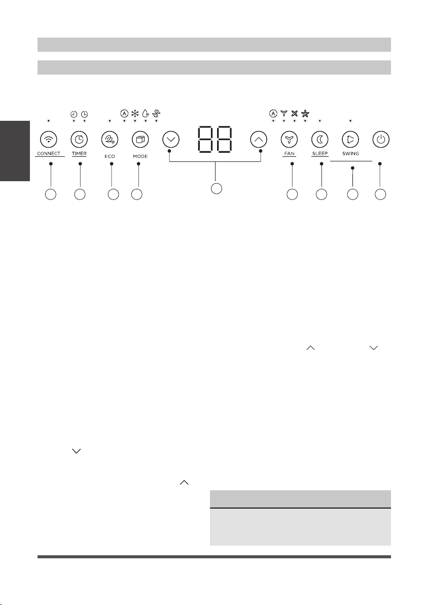
ELECTRONIC CONTROL OPERATING INSTRUCTIONS
Before you begin, thoroughly familiarize yourself with the control panel as shown below
and all its functions, then follow the symbol for the functions you desire. The unit can be
controlled by the control panel, remote control, smart phone app or voice control.
Instructions
Operating
CONNEXION MIN VENT VEILLE
2
3 4
1. ON/OFF Button
Press ON/OFF button to turn unit on or
off.
2. CONNECT Button
When connecting your air conditioner
to WiFi, press the CONNECT button
for 3 seconds to initiate the WiFi
connection mode. The display shows
‘AP’ to indicate the unit is in the WiFi
connection mod
section for further instructions.
If connection (router) is successful
within 8 minutes, the unit will exit WiFi
connection mode automatically and the
CONNECT indicator illuminates.
If connection failed within 8 minutes,
the unit exits WiFi connection mode
automatically and the CONNECT
indicator does not illuminate.
After WiFi connection is successful,
you can press and hold CONNECT an
DOWN (
for 3 seconds to turn off WiFi function
and the LED DISPLAY shows ‘OF’ for 3
seconds, press CONNECT and UP (
buttons at the same time to turn on WiFi
function and the LED DISPLAY shows
‘On’ for 3 seconds.
) buttons at the same time
5
e. Refer to the WiFi
6
3. Timer Button: Auto Start/Stop Feature
• When the unit is on, press the Timer
button. The “Timer off” LED indicator
light will illuminate indicating the Auto
stop feature has been activated.
• When the unit is off, press the Timer
button. The “Timer on” LED indicator
light will illuminate indicating the Auto
start feature has been activated.
• When the time of TIMER ON is displayed,
press the Timer button again. The TIMER
OFF indicator light illuminates. It indicates
the Auto Stop program has initiated.
• Press or hold the UP (
button to change the Auto time by 0.5 hour
increments, up to 10 hours, then at 1 hour
increments up to 24 hours. The control will
count down the time remaining until start.
• The selected time will register in 5
seconds, and the system will automatically
revert back to display the previous
temperature setting or room temperature
when the unit is on. (when the unit is off,
d
there is no display.)
• Turning the unit ON or OFF at any time
or adjusting the timer setting to 0.0 will
cancel the Auto Start/Stop timed program.
)
7 8 9
) or DOWN ( )
NOTICE
To cancel timer operation, press and
hold the timer button for 2 seconds until
the beep/buzzer is heard.
3s reset filter
Réinitialiser le filtre (3s)
1
Page 10
Page 11

4. EC0 Button
Press the ECO button to initiate the Energy
Saver function. This function is available
on COOL, DRY, and AUTO (only AUTOCOOLING and AUTO-FAN) modes. The fan
will continue to run for 3 minutes after the
compressor shuts off.
The fan then cycles on for 2 minutes
at 10 minute intervals until the room
temperature is above the set temperature,
at which time the compressor turns back
on and Cooling Starts.
5. MODE Button
• To choose the operating mode, press
the MODE button. Each time you press
the button, a mode is selected in a
sequence that goes from Auto, Cool,
Dry and Fan. The indicator light beside
the button will be illuminated and
remain on once that mode is selected.
• When the unit is turned off and back
on via the power button, the unit will
automatically switch on the Energy
Saver Function for the following modes:
Cool, Dry, Auto.
To operate on AUTO feature:
• When you set the air conditioner to
AUTO mode, it will automatically select
cooling or fan only operation, depending
on what temperature you have selected
and the current room temperature.
• The air conditioner will automatically
control the room temperature according
to the temperature you’ve set.
• In this mode, the fan speed cannot be
adjusted and is automatically controlled
based on the temperature setting and
room temperature.
To operate on COOL mode:
• Choose Cool Mode to set the cooling
function. Use the UP (
(
) buttons to choose the desired
) or DOWN
temperature. When Cool Mode is
selected, the fan speed can be adjusted
by pressing the FAN button.
To operate on DRY mode:
• In this mode, the air conditioner will
generally operate as a dehumidifier.
Since the conditioned space is a closed
or sealed area, some degree of cooling
will continue. On Dry mode, the fan
speed is not adjustable.
To operate on FAN mode:
• Use this function only when cooling
is not desired, such as for room air
circulation. You can choose any fan
speed you prefer.
• In Fan Only mode, the temperature can
not be adjusted and the display will show
the actual room temperature, not the set
temperature as in the cooling mode.
6. UP/DOWN Button
Press UP (
) or DOWN ( ) button to
change temperature setting.
7. FAN SPEED Button
Press FAN button to select the Fan Speed
in four steps - Auto, Low, Med or High.
Each time the button is pressed, the fan
speed mode is shifted.
8. SLEEP Button
Press SLEEP button to initiate the
sleep mode. In this mode the selected
temperature will increase (in cooling
mode) by 1°C (2°F) 30 minutes after
the mode is selected. The temperature
will then increase (in cooling mode) by
another 1°C (2°F) after an additional 30
minutes.
This new temperature will be maintained
for 7 hours before it returns to the
originally selected temperature.
This ends the Sleep mode and the unit
will continue to operate as originally
programmed. The Sleep mode program
can be cancelled at any time during
operation by pressing the SLEEP button
again.
Instructions
Operating
Page 11
Page 12
9. SWING Button
Use the SWING button to initiate the
auto swing feature for the outlet louver.
When the auto swing is on, pressing the
SWING button can stop the louver at the
desired angle.
Check Filter Feature:
The Check Filter feature is a reminder
Instructions
Operating
to clean the air filter for a more
efficient operation. The light above the
button will illuminate after 250 hours
of operation. After cleaning the filter,
press the SWING button for 3 seconds
to reset the Check Filter feature turning
the light off.
Error codes:
The unit may stop operation due to a
malfunction with the unit. If this occurs,
an error code may appear on the display
like below.
Wait 10 minutes as the problem may
resolve itself. If not, disconnect the
power, then connect it again. Turn the
unit on.
If the problem persists, disconnect the
power and contact customer service.
Error code appears and begins with the
letters as the following in the window
display of indoor unit:
EH(xx), EL(xx), EC(xx) , PH(xx), PL(xx),
PC(xx).
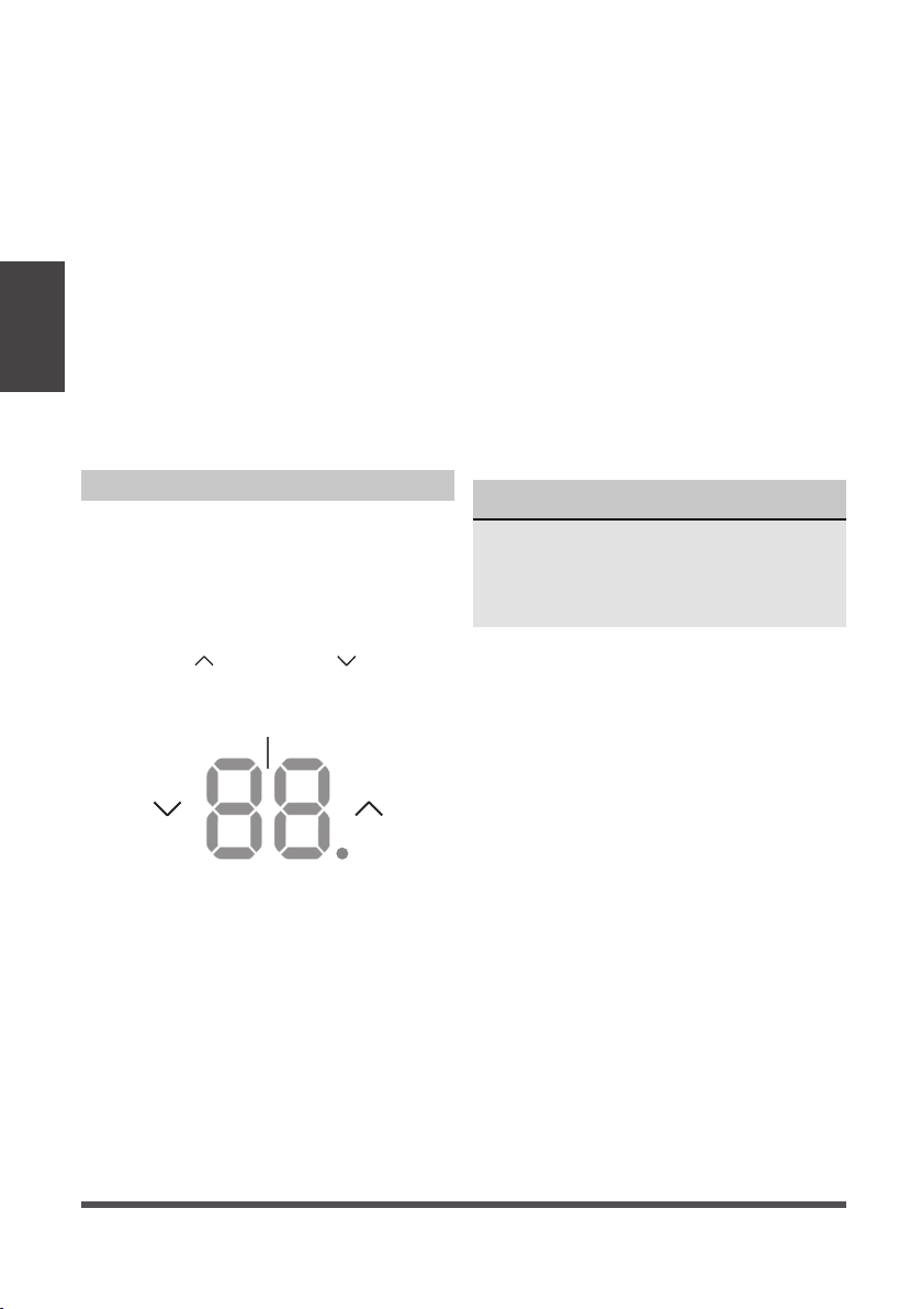
DISPLAYS
LED Display:
Shows the set temperature in “°C” or
“°F” and the Auto-timer settings. While
on Fan Only mode, it shows the room
temperature.
To change between °F and °C, press and
hold the UP (
at the same time for 3 seconds.
) and DOWN ( ) buttons
Display
NOTICE
If the unit turns off unexpectedly due to
the power being cut, it will automatically
restart with the previous function setting
when the power resumes.
Page 12
Page 13

INSTALLATION INSTRUCTIONS
Installation Video
Scan the QR code with your mobile device to
watch an installation video of the Midea U.
Instructions
Installation
Page 13
Page 14
Instructions
Installation
WARNING - Before You Begin
Read these instructions completely
and carefully.
• IMPORTANT - Save these instructions.
• IMPORTANT - Observe all governing
codes and ordinances.
We recommend that two people
install this product.
Proper installation is the responsibility
of the installer.
Product failure due to improper
installation is not covered under the
Limited Warranty.
You MUST use all supplied parts and
use proper installation procedures as
described in these instructions when
installing this air conditioner.
Do not, under any circumstances, cut
or remove the third (ground) prong
from the power cord.
Do not change the plug on the power
cord of the air conditioner.
Aluminum house wiring may present
special problems - consult a qualified
electrician.
When handling the air conditioner, be
careful to avoid cuts from sharp metal
edges and aluminum fins on front and
rear coils. Please wear cut-resistant
gloves.
Bracket should only be used for
its intended purpose. If not, the
warranty will be voided.
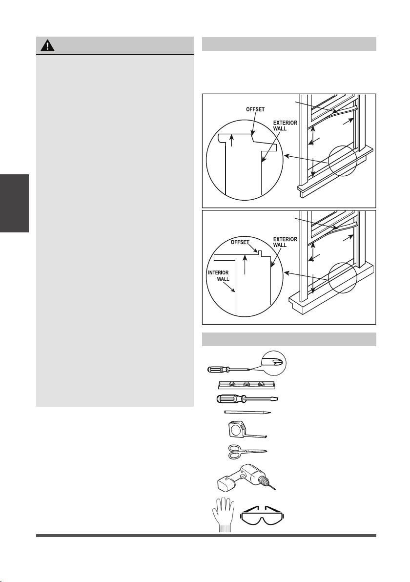
Window Requirements
Your air conditioner is designed to install in
standard double hung windows with opening
widths of 558mm to 914mm (22 to 36 inches)
and a window height of 349mm (13.75”).
SEAL FOAM
22" to 36"
(558 mm to 914mm)
INNER
WINDOW SILL
INTERIOR
WALL
13.75" min
(349 mm)
Wooden Windows
SEAL FOAM
22" to 36"
(558 mm to 914mm)
13.75" min
INNER
WINDOW SILL
(349 mm)
Vinyl-Clad Windows
Tools You Will Need
Phillips
Screwdriver
Level
Flathead Screwdriver
Pencil
Page 14
Ruler or tape measure
Scissors or knife
Drill and 1/8” drill bit
Proper PPE
Page 15

Installation Hardware
1/2” Type B Screw 2*
1/4” Type B Screw 2*
Right Extension Arm
(For 26”-36” windows)
Right Extension Arm – Short
(For 22”-26” windows)
Main Support Pin
Cotter Pin
1/2” Type A Screw 3*
Open Window Bracket – RH
Open Window Bracket – LH 1
Side Arm Foam 2
Rear Cross
Brace
Main Support
Window Sash Lock
Window Sash Foam
1Main Bracket
Window Sealing Foam
Bracket Sealing Foam
1
Additional Side Arm Foam
1
* Denotes extra hardware provided in
2*
separate bag.
2*
NOTICE
1” Type A Screw 2*
Save carton and these Installation
Instructions for future reference. The
1
carton is the best way to store unit during
winter, or when not in use.
If any piece of hardware is missing, DO
NOT INSTALL THE PRODUCT, and call
customer service at 1-866-646-4332.
1
1
1
1
2
Instructions
Installation
Right
Extension
Arm
Spring Push Pin
Left
Extension
Arm
Angled Support Arms
Horizontal Bracket
Fig. 1
1. Prepare the Window
Lower sash must open sufficiently to allow a clear vertical opening of 13.75 inches. Side
louvers and the rear of the AC must have clear air space to allow enough airflow through
the condenser for heat removal. The rear of the unit must be outdoors, not inside a
building or garage. Find the center of your window and lightly mark with a pencil.
Page 15
Page 16
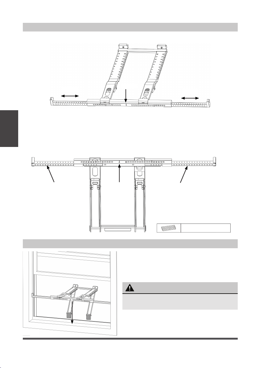
2. Prepare the Bracket
Remove the air conditioner, bracket and hardware from the carton and set on a flat surface.
Fig. 2
Adjust
Instructions
Installation
A. Pressing the Spring Push Pin, adjust the Left Extension Arm out and then install the
Center
Adjust
Right Extension Arm.
Measure the width of the inner windowsill on your window. Making sure that the center
of the bracket will line up with the center of the window, adjust the Extension Arms to
the width just measured. Note, the bracket will be offset to the left when centered.
B. Apply Bracket Sealing Foam strips to the bottom of the bracket as shown.
Apply Bracket
Sealing Foam
Fig. 3
Apply Bracket
Sealing Foam
Bottom View
Apply Bracket
Sealing Foam
Bracket Sealing Foam
Bracket Sealing Foam
3. Install Support Bracket
A. Install the Main Support Bracket into
the window opening. Ensure that the
Horizontal Bracket and Extension Arms are
located on the indoor side of the window.
Fig. 4
Page 16
WARNING
Maintain control of the bracket until
installation is complete.
Page 17

Vinyl Lip
OUTSIDE
INSIDE
Wooden Windows
INSIDE
Vinyl-Clad Windows
OUTSIDE
Fig. 5
Vinyl Type Windows with a Lipped Sill
A1. Secure the bracket to the windowsill by drilling 1/8” pilot holes and installing the
1/2” Type A screws as shown in Fig. 6.
Instructions
Installation
1/2” Type A
1/2” Type A
Fig. 6
Wooden Type Windows with a Flat Sill
A2. Secure the bracket to the windowsill by drilling 1/8” pilot holes and installing the
1/2” and 1” Type A screws as shown in Fig. 7.
1” Type A
1” Type A
1/2” Type A 1/2” Type A
Fig. 7
Depending on the
level used, place at
either location below
to check level.
Here is what
1/4 bubble on
the level
should look
like.
B. Move the Angled Support Arms
toward the exterior wall until
the feet touch the wall. Place
the level on the bracket and
adjust the Support Arms so that
it is level or tilted 1/4 bubble
downward and towards the
outside.
Fig. 8
Page 17
Page 18
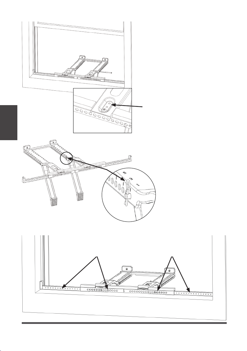
Fig. 9
C. Insert the Main Support Pin
through the holes the Main
Support and Angled Support Arm.
Using the numbers on the Main
Support, repeat the adjustment
for the other Angled Support Arm
matching the hole number from
the first support arm.
Instructions
Installation
If further adjustment is needed,
use alternate holes where the
Main Supports attach to the
Horizontal Bracket
D. Check the level again and
ensure the bracket feels secure.
After making any necessary
adjustments, insert the cotter
pins into the Main Support Pins.
Cotter Pin
Fig. 10
E. If necessary, cover the holes on the front of the bracket with the Bracket Sealing Foam.
Cover holes with
Bracket Sealing Foam
Cover holes with
Bracket Sealing Foam
Fig. 11
Page 18
Page 19

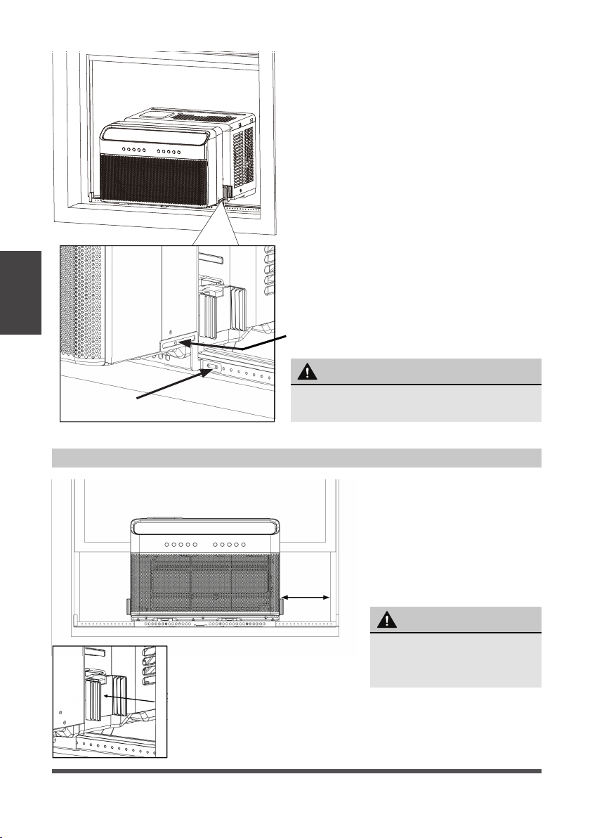
4. Install Air Conditioner
NOTICE
Measure the width of your window
track (the vertical track your window
slides up and down in) before installing
your air conditioner. If it measures 1/2“
or less, flip the Anti-Tip Bracket so the
small end faces out, then continue with
your air conditioner installation.
A. Set the air conditioner on top of the
support bracket. Ensure the grooves
on the bottom of the air conditioner
align with the Main Supports. Using
a level, check for proper tilt towards
the outside.
Fig. 12
B. Pull the window down into the slot to help align the unit in the correct location. Keep
the window partially inserted into the window slot to help support the air conditioner
during installation.
Fold down both Side Arm Hinges.
WARNING
Do not leave the unit unattended during
installation.
Fig. 13
This side faces indoors
Instructions
Installation
Fig. 14
Fig. 15
Page 19
Page 20
Instructions
Installation
Fig. 16
Use the 1/4”
Type B screw.
5. Foam Installation
C. Next, you must install the Open
Window Brackets using the provided
screws as shown.
Use the 1/2” Type B screw.
WARNING
Failing to install the Open Window Brackets
could cause injury or property damage.
Page 20
Fig. 17
A. Measure the distance
between the Side Arm
Hinge and the closest
part of the window frame
in line with the Side Arm.
Add 1/4” to this distance
and cut the Side Arm
Foam to length.
WARNING
Do not leave the unit
unattended during
installation.
Page 21

B. Apply Window Sealing Foam to the Side Arm Foam as shown. Note that the
Window Sealing Foam attaches to the side next to the air conditioner.”
Vinyl Type Windows with Lipped Sill
Air Conditioner Side
Side Arm Foam Side Arm FoamAir Conditioner Side
Wooden Type Windows with Flat Sill
Additional Side
Arm Foam
Instructions
Installation
Window
Sealing Foam
Window Sealing Foam
Window Sealing Foam
Fig. 18
Window
Sealing Foam
Window Sealing Foam
Window Sealing Foam
C. Insert Side Arm Foam into Side
Arm Hinge until the top front of
the Side Arm is flush with the
top of the hinge.”
To p
Front
Fig. 20
NOTICE
Repeat the side arm foam installation steps on the other side of the unit as well.
Fig. 19
Page 21
Page 22
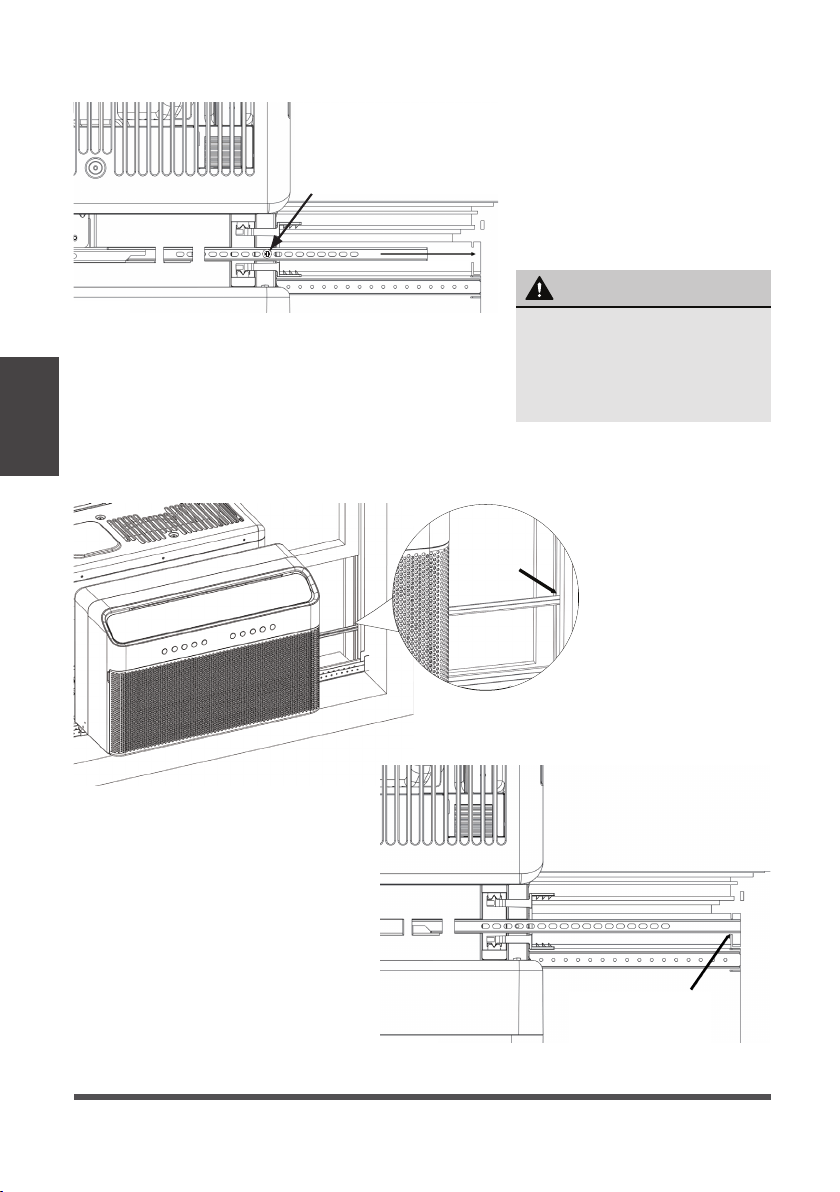
D. The Anti-Tip Brackets
must be extended into the
window track opening (the
vertical track your window
slides up and down in) until
they stop.
Secure the brackets in place
Top of Unit
Top view
The factory installed 1/2“ screw
must be re-used to secure the
Anti-Tip Bracket. Failing to use
this screw could damage the
air conditioner.
by using the provided 1/2“
Phillips head screw.
Extend into Window Track
WARNING
Fig. 21
Instructions
Installation
The images below show how the Anti-Tip Bracket is to be installed in the window track.
Note the Side Arm Foam was removed for illustration purposes only.
You must extend the
Anti-Tip Brackets into the
Window Track Opening.
Failure to follow this warning
may cause serious injury.
Fig. 22
Page 22
Fig. 23
Top view
Anti-Tip Bracket
Installed in Window
Track Opening
Page 23

E. Install a strip of Window Sealing
Foam to the bottom of your lower
sash sealing any small gaps between
the window and air conditioner. Then
close the window and check for gaps.
Fill any gaps with the included foam
as needed.
F. Extend the Integrated Window Locks
(located in the U channel) until they
contact the window. For additional
security you can install the optional
Sash Lock as shown.
Fig. 24
Fig. 25
Fig. 26
FOAM SEAL
G. To secure the lower sash in place,
attach right angle sash lock with 1/2”
Type A Screws as shown.
H. Cut window sash foam and insert it
in the space between the upper and
lower sashes.
Window Sash Foam
Window Sash Foam
Instructions
Installation
Page 23
Page 24

Instructions
Installation
Final Check: Review the installation
and check for any gaps or
openings to the outdoor air. Cover
these gaps with the provided
foam ensuring no outdoor air leaks
inside. See image for areas to
check for gaps.
Check for Gaps
Check
for Gaps
Fig. 27
IF AC IS BLOCKED BY STORM WINDOW
SASH
Storm window
frame or other
obstruction.
OUTSIDE INSIDE
Fig. 28
1-1/2" min
(38 mm)
Board thickness as
required, for proper
pitch to rear, along
entire sill. Fasten
with nails or screws.
Page 24
Add wood as shown, or remove
storm window before air
conditioner is installed.
If storm window frame must
remain, be sure the drain holes or
slots are not caulked or painted
shut. Accumulated rain water or
condensation must be allowed to
drain out.
You must secure the support
bracket to the added wood piece
using the provided 1” Type A
Screws. Refer to the Open Window
Bracket installation step.
Page 25

CARE AND CLEANING
CAUTION
Clean your air conditioner occasionally to keep it looking new. Be sure to unplug the
unit before cleaning to prevent shock or fire hazards.
Air Filter Cleaning
The air filter should be checked at
least once every two weeks to see if
cleaning is necessary. Trapped particles
in the filter can build up and cause an
accumulation of frost on the cooling coils
and reduce performance.
• Grasp the filter by the center and pull
up and out.
• Wash the filter using warm water. Rinse
filter thoroughly.
• Gently shake excess water from the filter. Be sure the filter is thoroughly dry
before replacing.
• Instead of washing, you may also vacuum the filter clean rather than washing.
NOTICE
Never use hot water over 40°C (104°F) to clean the air filter. Never atte mpt to
operate the unit without the air filter.
Care and
Cleaning
Cabinet Cleaning
• Be sure to unplug the air conditioner to prevent shock or fire hazard. The cabinet and
front may be dusted with an oil-free cloth or washed with a cloth dampened in a solution
of warm water and mild liquid dishwashing detergent. Rinse thoroughly and wipe dry.
• Never use harsh cleansers, wax, or polish on the air conditioner.
• Be sure to wring excess water from the cloth before wiping around the controls.
Excess water in or around the controls will cause damage to the air conditioner.
• Plug in air conditioner.
Winter Storage
If you plan to store the air conditioner during the winter, remove it carefully from the
window according to the installation instructions. Be careful not to spill any potentially
standing water from the unit’s base pan. If water is present, carefully drain it. Cover
the unit with plastic or return it to the original carton.
Page 25
Page 26

TROUBLESHOOTING TIPS
Before calling for service, review this list. It may save you time and expense. This list
includes common occurrences that are not the result of defective workmanship or
materials in this appliance.
Problem Solution
Wall plug disconnected. Push plug firmly into wall outlet.
Circuit breaker tripped. Reset circuit breaker.
Air conditioner
does not start.
Air from unit
does not feel
cold enough.
Troubleshooting
Tips
Air conditioner
cooling, but
room is too
warm- ice
forming on
cooling coil
behind air filter.
Air conditioner
cooling, but
room is too
warm- NO ice
forming on
cooling coil
behind air filter.
Check if the light on the plug is on. If it is off, press the RESET
button.
Power is OFF. Turn power ON.
Unit turned off and then on quickly. Turn unit off and wait 3 minutes
before restarting.
Room temperature below 17°C (62°F). Cooling may not occur until
room temperature rises above 17°C (62°F).
Temperature sensor behind the air filter is touching the cold coil.
Try to move it so it does not contact the cold coil.
Reset to a lower temperature.
Compressor shut-off by changing modes. Wait approximately
3 minutes and listen for compressor to restart when set in the
COOL mode.
Check for potential obstructions blocking the outdoor intake/
exhaust. Clear any obstructions.
Outdoor temperature below 18°C (64°F). To defrost the coil, set to
FAN ONLY mode.
Air filter may be dirty. Clean filter. Refer to Care and Cleaning
section. To defrost, set to FAN ONLY mode.
Thermostat set too cold for night-time cooling. To defrost the coil,
set to FAN ONLY mode. Then, set temperature to a higher setting
Dirty or restricted air filter. Clean filter. Refer to Care and Cleaning
section. To defrost, set to FAN ONLY mode.
Temperature is set too high, set temperature to a lower setting.
Air directional louvers positioned improperly. Position louvers for
better air distribution.
Front of unit is blocked by drapes, blinds, furniture, etc. - restricts
air distribution. Clear obstruction in front of unit.
Any open doors, windows, or registers may allow cold air to escape.
Close any doors, windows, or registers.
The room may be too warm. Allow additional time to remove
“stored heat” from walls, ceiling, floor and furniture.
.
Page 26
Page 27

Problem Solution
Air conditioner
turns on and
off rapidly.
Dirty air filter- air restricted. Clean air filter.
Outside temperature extremely hot. Set FAN speed to a higher
setting to bring air past cooling coils more frequently.
Check for potential obstructions blocking the outdoor intake/
exhaust. Clear any obstructions.
Noise when
unit is cooling.
Water dripping
INSIDE when
unit is cooling.
Water dripping
OUTSIDE when
unit is cooling.
Remote sensing
deactivating
prematurely
(some models).
Air movement sound. This is normal. If too loud, set to a slower FAN setting.
Window vibration - poor installation. Refer to installation
instructions or check with installer.
Improper installation. Tilt air conditioner slightly to the outside to
allow water drainage.
Refer to installation instructions - check with installer.
Unit removing large quantity of moisture from humid room. This is
normal during excessively humid days.
Remote control not located within range. Place remote control
within 26 feet & 180°, radius of the front of the unit, and pointed
in the general direction of the air conditioner unit.
Remote control signal obstructed. Remove obstruction.
Room too cold. Temperature setting too low. Increase temperature setting.
Noise when
unit starts.
Window does
not insert into
the U-shaped
slot.
A “da-da” sound may occur for thirty seconds when the unit is
turned on due to the compressor starting. It is normal.
Ensure that the “U-shaped” slot is in line with the window, if not,
align the slot with the window.
Ensure that the unit is not slanted too much to cause interference
with the top of the unit. Reference the installation instructions for
more information.
Unit will not
connect to
For additional support and troubleshooting tips, follow the link in
this QR code:
WiFi or App
does not work
(some models).
Troubleshooting
Tips
Page 27
Page 28

REMOTE CONTROL AND APP INSTRUCTIONS
Handling the Remote Control
Location of the remote control
Use the remote control within a distance of 8m (26 ft).
from the air conditioner, pointing it towards the unit.
The unit will beep when it receives a signal.
CAUTION
• The air conditioner will not operate if curtains, doors
or other materials block the signals from the remote
control to the unit.
• Prevent any liquid from spilling onto the remote
26 ft (8 meters)
Inserting and Replacing Batteries
control. Do not expose the remote control to direct
sunlight or heat.
• If the infrared signal receiver on the indoor unit is
exposed to direct sunlight, the air conditioner may
not function properly. Use curtains to prevent the
sunlight from falling on the receiver.
• If other electrical appliances react to the remote
control, either move these appliances or consult
your local dealer.
Remote Control
Instructions
and App
Page 28
Your air conditioning unit may come
with two batteries (some units). Put the
batteries in the remote control before use.
1. Slide the back cover from the remote
control downward, exposing the battery
compartment.
2. Insert the batteries, paying attention to
match up the (+) and (-) ends of the
batteries with the symbols inside the
battery compartment.
3.
Slide the battery cover back into place.
-Do not mix old and new batteries;
-Do not mix alkaline, standard
(Carbon-Zinc) or rechargeable (Ni-Cd,
Ni- MH, etc.) batteries.
Page 29

Remote Control Specifications
Rated Voltage 3.0V ( Dry batteries R03/LR03x2)
Signal Receiving Range 8m (26ft)
Environment -5 °C ~ 60 °C (23°F ~ 140°F)
Function Buttons
Turns the unit on or off.
Increases temperate in
1°F (1°C) increments.
Max. temperature is
86°F (30°C).
Scrolls through operation
functions as follows:
Comfort Sense ( )
AP mode ( ) Fresh...
The selected symbol will
flash on the display area,
press the OK button to
confirm.
Decreases temperature
in 1°F (1°C) increments.
Min. temperature is
60°F (16°C).
Switches the fan
speed as follows:
Auto
Medium High ...
ON/OFF
TEMP
SET
TEMP
FAN SPEED
Low
MODE
Switches the operating
modes as follows:
Cool Dry Fan
Auto
ENERGY SAVER
Press this button to toggle
energy saver mode.
OK
Press to send the desired
settings to the AC unit.
SWING
Starts and stops the
horizontal louver
movement.
TIMER OFF
Sets timer to turn unit off
(see How to Use Basic
Functions for instructions)
°C/°F
Change the temperature
units between °C and °F.
.
Remote Control
Instructions
and App
TIMER ON
Sets timer to turn
unit on (see How
to Use Basic
Functions for
instructions).
SLEEP
Saves energy during
sleeping hours.
LED
Turn the unit’s LED display and
control panel beeps on or off.
Page 29
Page 30

Remote Screen Indicators
Information is displayed when the remote control is powered on.
Sleep mode display
Comfort Sense feature display
Wireless control feature display
Low battery detection display
(If flashes)
MODE display
Transmission Indicator
Lights up when remote
sends signal to indoor
unit.
TIMER ON display
TIMER OFF display
Displays the current mode,
including:
ECO display
Not available for this unit
Remote Control
Instructions
and App
FAN SPEED display
Displays selected
fan speed:
LOW
MED
HIGH
AUTO
This fan speed can not be
adjusted in AUTO or DRY
mode.
Page 30
Horizontal louver
auto swing display
Temperature/Timer/
Fan speed display
Displays the set temperature
by default, or fan speed or
timer setting when using
TIMER ON/OFF functions.
Temperature range:
16-30°C / 60-86°F
Timer setting range:
0-24 hours
This display is blank when
operating in FAN mode.
Page 31

Setting the TIMER
TIMER ON/OFF - Set the amount of time after which the unit will automatically turn on/off.
TIMER ON SETTING
Press TIMER ON
button to initiate the
ON time sequence.
Press up or down button for
multiple times to set the desired
time to turn on the unit.
x5
TIMER OFF SETTING
Press TIMER OFF
button to initiate the
OFF time sequence.
Press up or down button for
multiple times to set the desired
time to turn off the unit.
x10
NOTICE
1. When setting the TIMER ON or TIMER OFF, the time will increase by 30 minutes
increments with each press, up to 10 hours. After 10 hours and up to 24, it will increase in
1 hour increments. (For example, press 5 times to get 2.5h, and press 10 times to get 5h,).
The timer will revert to 0.0 after 24.
2. Cancel either function by setting its timer to 0.0h.
Point remote to unit and wait
1sec, the TIMER ON will be
activated.
1sec
Point remote to unit and wait
1sec, the TIMER OFF will be
activated.
1sec
TIMER ON & OFF SETTING (EXAMPLE)
Keep in mind that the time periods you set for both functions refer to hours after the current time.
xnxn
Example: If current timer is
1:00PM, to set the timer as
above steps, the unit will turn
on 2.5h later (3:30PM) and
turn o at 6:00PM.
Timer
starts
Current
time 1PM
xn
2:00PM 3:00PM
2.5 hours later
5 hours later
Unit turns
ON
3:30PM
4PM 5PM
Unit turns
OFF
6PM
Page 31
Remote Control
Instructions
and App
Page 32

Remote Control
Instructions
and App
DECLARATION OF CONFORMITY
We hereby declare that this AC is in compliance with the essential requirements and
other relevant provisions of Directive 1999/5/EC.
SPECIFICATION OF WIRELESS MODULE
Model: US-OSK103 Dimensions: 41 x 24 x 5 (mm)
Standard: IEEE 802.11 b/g/n Operation Temperature: 0°C ~ 45°C / 32°F ~ 113°F.
Antenna Type: External
omnidirectional Antenna
Frequency: 2.4 GHz (wireless) Power Input: DC 5V/300 mA
Maximum Transmitted Power:
15 dBm Max
Operation Humidity: 10% ~ 85%
PRECAUTIONS
1. Supports operating systems: iOS 7+ or Android 4+.
2. In the event of a OS update, there may be a delay between the update of the OS
and a related software update during which your OS may or may not be supported
until a new version is released. Your specific mobile phone or problems in your
network may prevent the system from working and Midea will not be responsible
for any problems that could be caused by incompatibility or network issues.
3. This Smart AC only supports WPA-PSK/WPA2-PSK (recommended) encryption.
4. To ensure proper scanning of the QR code, your smart phone must have at least a
5-megapixel camera.
5. Due to unstable network connectivity, requests may time out. If this happens, rerun the network configuration.
6. Due to unstable network connectivity, commands may time out. If this happens,
the smartphone app and the actual product may display conflicting information.
The information displayed on the actual product is always the most accurate
available. Refresh the app to re-sync.
NOTICE
Midea will not be responsible for any problems that could be caused by
incompatibility or network issues, your wireless router and mobile phone.
Page 32
Page 33

SYSTEM OVERVIEW
Devices required to use the Smart AC:
1. Smart Phone with compatible iOS or Android system.
2. Wireless Router
3. Smart Air Conditioner
DOWNLOAD AND INSTALL THE APP
Android QR code Apple QR code
Scan to download app.
• You can also go to Google Play or App Store and search for Midea Air.
NOTICE
All the images in this manual are for reference only, your product and app may look
slightly different. The actual product and app instructions have to be considered.
Page 33
Remote Control
Instructions
and App
Page 34

CREATE YOUR ACCOUNT
• Make sure your smartphone is connected to your wireless router and your wireless
router has a working 2.4GHz internet connection.
• It is recommended to activate your account immediately to be able to recover your
password by email.
6.1 Press “Sign Up”. 6.2 Enter your email address and password.
Remote Control
Instructions
and App
6.3 Press “Registration”. 6.4 If you forget your password, press
“Forgot password?” on the main
menu and enter your email address.
Then press “Reset Password”.
NOTICE
• Make sure your smartphone is able to connect to the wireless network which will be used.
• Make sure also that the device is not connecting to other networks in range.
Page 34
Page 35

WARRANTY
These products have been made to quality standards and are guaranteed for domestic use
against manufacturing faults.
One (1) year full warranty from original purchase date and limited 2nd through 5th year
sealed system warranty if used for normal domestic purposes.
This warranty does not affect your statutory rights. In case of any malfunction of your
product (failure, missing part, etc.), please contact one of our service technicians at our tollfree service line at 1-866-646-4332 from 8 AM to 6 PM EST, Monday to Friday, and 8 AM to 4
PM EST, Saturday. Midea reserves the right to repair or replace the defective product, at its
discretion.
Any warranty is invalid if the product has been overloaded or subject to neglect, improper
use or an attempted repair other than by an authorized agent. Heavy-duty or daily
professional/commercial usage are not guaranteed. Due to continuous product
improvement, we reserve the right to change product specifications without prior notice.
For instructions on how to properly drain Freon, please contact our customer service at
1-866-646-4332. Thank you.
Page 35
Warranty
Page 36

Page 37

Climatiseur de fenêtre
MAW
Capacité : 10000BTU/h
MANUEL DE L'UTILISATEUR
Avis d'avertissement : Avant d'utiliser ce
produit, veuillez lire attentivement ce
manuel et le conserver pour référence
ultérieure. Pour toute assistance supplémentaire, veuillez appeler le service
clientèle au 1-866-646-4332.
La conception et les spécifications sont
susceptibles d'être modifiées sans préavis
pour améliorer le produit. Consultez votre
revendeur ou le fabricant pour plus de
détails.
version EB -0 092 -2 2002200 (PREVIEW06)
MW10MSWBA4RCM
midea.com
Page 38

Manuel du propriétaire
PRÉCAUTIONS DE SÉCURITÉ
INSTRUCTIONS D'UTILISATION
INSTRUCTIONS D'INSTALLATION
LES SOINS ET LE NETTOYAGE
CONSEILS DE DÉPANNAGE
TÉLÉCOMMANDE ET INSTRUCTIONS DE L'APPLICATION
GARANTIE
Lire ce manuel
Vous trouverez à l'intérieur de nombreux conseils utiles sur l'utilisation et l'entretien de votre climatiseur. Un petit soin préventif de votre part peut vous faire économiser beaucoup de temps et
d'argent pendant la durée de vie de votre climatiseur. Vous trouverez de nombreuses réponses aux
problèmes courants dans les conseils de dépannage - vous devriez pouvoir résoudre la plupart
d'entre eux rapidement avant d'appeler le service après-vente. Ces instructions peuvent ne pas
couvrir toutes les conditions d'utilisation possibles, c'est pourquoi il faut faire preuve de bon sens et
d'attention à la sécurité lors de l'installation, de l'utilisation et de l'entretien de ce produit.
ATTENTION
• Pour obtenir de l'aide, veuillez appeler le Centre de services au 1-866-646-4332.
• Cet appareil n'est pas destiné à être utilisé par des personnes (y compris les enfants) dont les
capacités physiques, sensorielles ou mentales sont réduites ou qui manquent d'expérience et
de connaissances, sauf si elles ont été supervisées ou ont reçu des instructions concernant
l'utilisation de l'appareil par une personne responsable de leur sécurité.
• Les enfants doivent être surveillés afin de s'assurer qu'ils ne jouent pas avec l'appareil.
• L'appareil doit être installé conformément aux réglementations nationales en matière de
câblage.
• Ne faites pas fonctionner votre climatiseur dans une pièce humide telle qu'une salle de bain ou
une buanderie.
Page 39

PRÉCAUTIONS DE SÉCURITÉ
Pour éviter de blesser l'utilisateur ou d'autres personnes et de causer des dommages matériels, les
instructions indiquées ici doivent être suivies. Une utilisation incorrecte due à l'ignorance des
instructions peut causer des dommages ou des dégâts. Le niveau de risque est indiqué par les
indications suivantes.
AVERTISSEMENT
Ce symbole indique une situation dangereuse qui, si elle n'est pas
évitée, pourrait entraîner la mort ou des blessures graves.
Précautions
Sécurité
ATTENTION
AVIS
Ce symbole indique une situation dangereuse qui, si elle n'est pas
évitée, pourrait entraîner des blessures légères ou modérées.
Ce symbole concerne les pratiques non liées à des blessures physiques.
AVERTISSEMENT
• Assurez-vous que le climatiseur a été installé correctement et en toute sécurité conformément
aux instructions d'installation figurant dans ce manuel. Conservez ce manuel pour une
éventuelle utilisation future lors du retrait ou de l'installation de cet appareil.
• Branchez correctement la fiche du cordon d'alimentation. Sinon, elle peut provoquer un choc
électrique ou un incendie en raison d'une production excessive de chaleur.
• Il ne faut pas modifier la longueur du cordon d'alimentation ni partager la prise de courant avec
d'autres appareils, car cela pourrait provoquer un choc électrique ou un incendie en raison
d'une surchauffe.
• Assurez-vous toujours qu'il y a une bonne mise à la masse. Une mauvaise mise à la masse
peut provoquer un choc électrique.
• Débranchez l'appareil si vous remarquez des bruits ou des odeurs inhabituels ou de la fumée
en provenance de celui-ci. Un produit endommagé peut provoquer un incendie et un choc
électrique.
• En cas de fuite de gaz provenant d'un autre appareil, il faut ventiler la pièce avant de faire
fonctionner le climatiseur.
• Ne faites pas fonctionner ou n'arrêtez pas l'appareil en insérant ou en retirant la fiche du
cordon d'alimentation.
• N'utilisez pas l'appareil avec des mains mouillées ou dans un environnement très humide.
Cela pourrait provoquer un choc électrique.
• Ne laissez pas l'eau entrer en contact avec les pièces électriques. Cela pourrait provoquer une
panne ou un choc électrique.
• N'utilisez pas la prise de courant si elle est lâche ou endommagée. Elle peut provoquer un
incendie et un choc électrique.
• N'utilisez pas ou ne gardez pas le cordon d'alimentation à proximité d'appareils de chauffage.
Cela peut provoquer un incendie et un choc électrique.
• N'utilisez pas d'appareils ou de matériels pour l'installation qui ne sont pas mentionnés dans
ce manuel.
Page 40

Précautions
Sécurité
AVERTISSEMENT
• Ne pas démonter ou modifier l'appareil, car cela pourrait provoquer une panne et un choc
électrique.
• N'endommagez pas et n'utilisez pas un autre cordon d'alimentation, car cela pourrait
provoquer un incendie et un choc électrique.
Si le cordon d'alimentation est endommagé, il doit être remplacé par le fabricant ou un centre
de service agréé ou une personne ayant une qualification similaire afin d'éviter tout risque.
• Ne dirigez pas le flux d'air directement sur les personnes pour éviter tout risque pour la santé.
• N'ouvrez pas l'appareil pendant son fonctionnement, car cela pourrait provoquer un choc
électrique.
• N'utilisez pas le cordon d'alimentation à proximité de gaz inflammable ou de produits inflammables, tels que l'essence, le benzène, les diluants, etc.
Cela peut provoquer une explosion ou un incendie.
• Ne laissez pas les enfants s'accrocher au climatiseur ou à son support.
Une blessure grave peut se produire.
• Évitez tout risque d'incendie ou de choc électrique. N'utilisez pas de rallonge ou de prise
d'adaptateur. Ne retirez aucune broche du cordon d'alimentation.
• Assurez-vous que le climatiseur est correctement mis à la masse. Pour éviter les risques de
choc électrique et d'incendie, il est important que la masse soit correctement mise à la terre.
Le cordon d'alimentation est équipé d'une fiche à trois broches avec mise à la terre pour la
protection contre les risques d'électrocution.
• Votre climatiseur doit être utilisé dans une prise murale correctement mise à la terre. Si la
prise murale que vous comptez utiliser n'est pas correctement mise à la terre ou protégée par
un fusible à retardement ou un disjoncteur, demandez à un électricien qualifié d'installer la
prise appropriée. Assurez-vous que la prise est accessible après l'installation de l'appareil.
• Assurez-vous que le
Cette information se trouve sur la plaque de série, qui se trouve sur le côté de l'armoire et
derrière la grille.
• Ne buvez pas l'eau d'évacuation. Elle peut contenir des moisissures et des bactéries qui
peuvent entraîner la mort si elles sont ingérées.
service électrique est adéquat pour la m odèle que vous avez choisie.
ATTENTION
• Lorsque le filtre à air doit être retiré, ne touchez pas les parties métalliques de l'appareil.
Cela pourrait provoquer des blessures.
• Lorsque l'appareil a besoin d'être nettoyé, éteignez-le et coupez le disjoncteur. Ne nettoyez
pas l'appareil lorsqu'il est sous tension, car cela pourrait provoquer un incendie, un choc
électrique ou des blessures.
• Ne placez pas d'obstacles autour des entrées d'air ou à l'intérieur de la sortie d'air
• Nettoyez avec un chiffon doux uniquement. N'utilisez pas de détergents puissants
contenant de la cire ou des diluants, car cela pourrait endommager l'appareil.
• Faites preuve de prudence lors du déballage et de l'installation. Les bords tranchants
pourraient causer des blessures.
Page 41

ATTENTION
• Ne nettoyez pas le climatiseur avec de l'eau, car l'eau pourrait pénétrer dans l'appareil et
dégrader l'isolation, ce qui pourrait entraîner un choc électrique.
• Évitez de placer un animal de compagnie ou une plante d'intérieur dans un endroit où il
sera exposé à un flux d'air direct, ce qui pourrait blesser l'animal ou nuire à la plante.
• Tenez la fiche par la tête de la prise de courant lorsque vous la retirez.
Sinon, vous risquez de provoquer un choc électrique et des dommages.
• Veillez à ce que l'installation soit correctement fixée pour éviter que le produit ne tombe
éventuellement.
• Ne placez pas d'objets lourds sur le cordon d'alimentation et veillez à ce que le cordon ne
soit pas comprimé.
Sinon, il y a risque d'incendie ou de choc électrique.
• Si de l'eau est renversée sur l'appareil, éteignez l'appareil et coupez le disjoncteur. Isolez
l'alimentation en débranchant la fiche d'alimentation et contactez un technicien de
maintenance qualifié.
• N'utilisez pas l'appareil à proximité d'une cuisinière à gaz ou d'autres appareils à gaz, car
le flux d'air peut affecter la combustion du gaz.
• Veillez à ne pas l'utiliser à d'autres fins que le confort de la chambre.
N'utilisez pas ce climatiseur pour préserver des appareils de pointe, de la nourriture, des
animaux domestiques, des plantes et des objets d'art. Il pourrait provoquer une détérioration.
• Éteignez l'interrupteur principal si l'appareil ne doit pas être utilisé pendant une période
prolongée.
• Insérez toujours les filtres de manière sûre. Nettoyez le filtre une fois toutes les deux
semaines.
Le fonctionnement sans filtre peut entraîner une défaillance.
Précautions
Sécurité
Page 42

Précautions
Sécurité
Fonctionnement du dispositif de courant
Branchez et appuyez
sur RÉINITIALISER
RÉINITIALISER
TEST
Prise murale de type masse
Il ne faut en aucun cas
couper, enlever ou
contourner la broche
de masse.
Le cordon d'alimentation contient un appareil de
mesure du courant qui détecte les dommages
causés au cordon d'alimentation. Testez votre
cordon d'alimentation comme suit :
1. Branchez le climatiseur.
2. Le cordon d'alimentation aura DEUX boutons
sur la tête de la prise. Appuyez sur le bouton
TEST. Vous remarquerez un clic lorsque le
bouton RÉINITIALISER apparaîtra.
3. Appuyez sur le bouton RÉINITIALISER. Vous
remarquerez un clic lorsque le bouton
s'enclenche.
4. Le cordon d'alimentation alimente maintenant
l'appareil en électricité. (Sur certains produits,
cela est également indiqué par un voyant sur
la tête de la prise).
AVIS
Le cordon d'alimentation de ce climatiseur
contient un dispositif de détection de courant
conçu pour réduire le risque d'incendie.
Si le cordon d'alimentation est endommagé,
il ne peut pas être réparé. Il doit être
remplacé par un cordon du fabricant.
Cordon d'alimentation avec prise de masse à 3
broches et dispositif de détection de courant
AVIS
• N'utilisez pas ce dispositif pour allumer ou éteindre l'appareil.
• Assurez-vous toujours que le bouton RÉINITIALISER est bien enfoncé pour un fonctionnement
correct.
• Le cordon d'alimentation doit être remplacé s'il ne se réinitialise pas lorsque le bouton TEST est
enfoncé, ou s'il ne peut pas être réinitialisé. Veuillez contacter le service clientèle.
Page 43

Précautions
Sécurité
Attention : Risque d'incendie/ matériaux
(Requis pour les appareils R32/R290
EXPLICATION DES SYMBOLES AFFICHÉS SUR L'APPAREIL
inflammables
uniquement)
AVER-
TISSE-
MENT
ATTENTION
ATTENTION
ATTENTION
Ce symbole indique que cet appareil a utilisé un réfrigérant inflammable. Si le fluide frigorigène fuit et est exposé à une source d'inflamma-
tion externe, il y a un risque d'incendie.
Ce symbole indique que le manuel d'utilisation doit être lu attentivement.
Ce symbole indique qu'un personnel de service doit manipuler cet
équipement en se référant au manuel d'installation.
Ce symbole indique que des informations sont disponibles, telles que
le manuel d'utilisation ou le manuel d'installation.
REMARQUE IMPORTANTE : Lisez attentivement
ce manuel avant d'installer ou d'utiliser votre
nouveau climatiseur. Veillez à conserver ce
manuel pour toute référence ultérieure.
AVERTISSEMENT
• N'essayez pas d'accélérer le processus de décongélation ou de nettoyage qui ne sont pas
recommandés par le fabricant.
• L'appareil doit être stocké dans une pièce sans source d'inflammation fonctionnant en continu
(par exemple, des flammes nues ou un appareil à gaz en fonctionnement) ou une source
d'inflammation (par exemple, un chauffage électrique en fonctionnement) à proximité de
l'appareil. L'appareil doit également être stocké dans un local sans source d'inflammation.
• Ne pas percer ou brûler.
• Sachez que les réfrigérants peuvent ne pas contenir d'odeur.
• Maintenez les ouvertures de ventilation libres de toute obstruction.
• L'appareil ne doit être réparé que par un réparateur agréé Midea, veuillez appeler le service
clientèle au 1-866-646-4332 pour obtenir de l'aide.
• Le réfrigérant inflammable R32 est utilisé dans les climatiseurs. Veuillez suivre attentivement
les instructions pour manipuler, installer, nettoyer et entretenir le climatiseur afin d'éviter tout
dommage ou danger. Ne jetez pas le climatiseur dans les ordures ménagères. Contactez un
organisme qualifié pour une élimination appropriée.
• Aucun feu ouvert ou dispositif produisant des étincelles ne doit se trouver autour du climatiseur
pour éviter de provoquer l'inflammation du réfrigérant inflammable utilisé. Veuillez suivre
attentivement les instructions pour stocker ou entretenir le climatiseur afin d'éviter tout
dommage mécanique.
Page 44

INSTRUCTIONS D'UTILISATION
Sons normaux
Fonctionnement
Instructions
Vibration
L'appareil peut vibrer et
faire du bruit en raison
d'une mauvaise
construction des murs
ou des fenêtres ou d'une
installation incorrecte.
Bruit aigu
Les compresseurs à haut rendement peuvent avoir un son aigu
pendant le cycle de refroidissement.
Le bruit de l'air qui s'engouffre
Devant l'appareil, vous
pouvez entendre le bruit de
l'air qui s'écoule par le ventilateur.
Le son du
chatouillement
Les gouttelettes d'eau qui
frappent le condenseur
pendant le fonctionnement
normal peuvent provoquer un
bruit de ruissellement.
Gargouillis/sifflement
Des gargouillements ou des
sifflements peuvent être
entendus en raison du
réfrigérant qui circule dans
l'évaporateur pendant le
fonctionnement normal.
Performance sonore
Le tableau suivant présente les données relatives aux performances sonores de ces climatiseurs
de fenêtre. Veuillez utiliser votre numéro de modèle spécifique pour faire référence au numéro de
puissance sonore correct dans le tableau.
Numéro de modèle
MW12MSWBA4RCM
* selon ISO 3744 à faible vitesse de ventilation
Puissance sonore, dB(A)*
42
AVIS
Toutes les illustrations de ce manuel ont pour seul but de fournir des explications. L'installation
réelle peut varier.
Page 45

Fonctionnement du climatiseur
AVERTISSEMENT
Pour réduire le risque d'incendie, de choc électrique ou de blessure aux personnes ou aux biens,
lisez les PRÉCAUTIONS DE SÉCURITÉ avant d'utiliser cet appareil.
Fonctionnement du
refroidissement
Température extérieure : 18 °C ~ 43 °C / 64 °F ~ 109 °F
Température intérieure : 16 °C ~ 32 °C / 60 °F ~ 90 °F
AVIS
• L'humidité relative de la pièce doit être inférieure à 80 %. Si l'appareil est utilisé dans un état où
l'humidité relative est supérieure à 80 %, il y aura de l'eau condensée sur la surface de l'appar-
eil.
• Les performances peuvent être réduites en dehors de ces températures de fonctionnement.
AVIS
Attendez toujours 3 minutes lorsque vous éteignez puis rallumez l'appareil, ou lorsque vous
passez du mode « froid » au mode « ventilateur » et que vous revenez au mode « froid ». Cela
permet d'éviter que le compresseur ne soit endommagé.
Pour commencer à faire fonctionner le climatiseur, suivez les étapes suivantes :
1. Branchez le climatiseur (veillez à suivre les instructions du cordon d'alimentation).
2. Allumez le climatiseur à l'aide du bouton MARCHE/ARRÊT.
3. Réglez le thermostat sur la température la plus froide.
4. Sélectionnez le réglage du mode « Froid».
5. Ajustez la grille pour une circulation d'air confortable (voir Grilles d'aération directionnelles).
6. Une fois que la pièce a refroidi, réglez le thermostat sur le réglage que vous trouvez le plus confortable.
7. Assurez-vous que la circulation de l'air à l'intérieur et à l'extérieur n'est pas entravée par quoi que
ce soit.
Persiennes directionnelles de l'air
Les persiennes vous permettront de diriger le flux
d'air vers le haut ou le bas (sur certains modèles) et
vers la gauche ou la droite dans toute la pièce selon
les besoins. Utilisez le bouton BALANCEMENT
jusqu'à ce que vous obteniez la direction souhaitée
vers le haut ou vers le bas.
Déplacez les persiennes d'un côté à l'autre jusqu'à
obtenir la direction gauche/droite souhaitée.
Utiliser la touche BALANCEMENT pour
le sens de montée et de descente
Fonctionnement
Instructions
Régler les persiennes pour la direction
gauche/droite
Direction de l'air
Page 46

Avant de commencer, familiarisez-vous avec le panneau de contrôle comme indiqué ci-dessous et toutes
ses fonctions, puis suivez le symbole correspondant aux fonctions que vous souhaitez. L'appareil peut être
commandé par le panneau de contrôle, la télécommande, l'application smart phone ou la commande
vocale.
Fonctionnement
Instructions
Caractéristiques des climatiseurs
MODE D'EMPLOI DE LA COMMANDE ÉLECTRONIQUE
CONNEXION MIN VENT VEILLE
2
3 4
1. Bouton MARCHE/ARRÊT
Appuyez sur le bouton MARCHE/ARRÊT
pour allumer ou éteindre l'appareil.
2. Bouton CONNECTER
Lorsque vous connectez votre climatiseur au
WiFi, appuyez sur le bouton CONNECTER
pendant 3 secondes pour lancer le mode de
connexion WiFi. L'écran affiche « AP » pour
indiquer que l'appareil est en mode de
connexion WiFi. Reportez-vous à la section
WiFi pour de plus amples instructions.
Si la connexion (routeur) est réussie dans les
8 minutes, l'unité sortira automatiquement du
mode de connexion WiFi et le voyant
CONNECTER s'allumera.
Si la connexion échoue dans les 8 minutes,
l'unité quitte automatiquement le mode de
connexion WiFi et le voyant CONNECTER ne
s'allume pas.
Une fois la connexion WiFi réussie, vous
pouvez appuyer et maintenir enfoncés les
boutons CONNECTER et BAS ( ) en même
temps pendant 3 secondes pour désactiver la
fonction WiFi et l'affichage LED indique 'OF'
pendant 3 secondes, appuyer sur les boutons
CONNECTER et HAUT ( ) en même temps
pour activer la fonction WiFi et l'affichage
LED indique 'On' pendant 3 secondes.
5
6
3. Bouton de minuterie : Fonction de démarrage/arrêt
automatique
• Lorsque l'appareil est allumé, appuyez sur le bouton
Minuterie. Le voyant LED « Minuterie en arrêt »
s'allumera, indiquant que la fonction d'arrêt automatique
a été activée.
• Lorsque l'appareil est éteint, appuyez sur le bouton
Minuterie. Le voyant LED « Minuterie en marche »
s'allumera, indiquant que la fonction de démarrage
automatique a été activée.
• Lorsque l'heure de la mise en MINUTERIE EN MARCHE
est affichée, appuyez à nouveau sur le bouton de la
minuterie. Le voyant lumineux MINUTERIE EN ARRÊT
s'allume. Il indique que le programme d'arrêt automatique a été lancé.
• Appuyez ou maintenez enfoncée la touche HAUT (
BAS ( ) pour modifier l'heure automatique par
incréments de 0,5 heure, jusqu'à 10 heures, puis par
incréments de 1 heure jusqu'à 24 heures. La commande
décompte le temps restant jusqu'au démarrage.
• L'heure sélectionnée sera enregistrée en 5 secondes, et
le système reviendra automatiquement à l'affichage du
réglage de température précédent ou de la température
ambiante lorsque l'appareil est en marche. (lorsque
l'appareil est éteint, il n'y a pas d'affichage).
• La mise en MARCHE ou L'ARRET de l'appareil à tout
moment ou le réglage de la minuterie à 0,0 annule le
programme de démarrage/arrêt automatique.
7 8 9
AVIS
Pour annuler le fonctionnement de la minuterie,
appuyez sur le bouton de la minuterie et
maintenez-le enfoncé pendant 2 secondes jusqu'à
ce que le signal sonore/tambour se fasse entendre.
3s reset filter
Réinitialiser le filtre (3s)
1
) ou
Page 47

4. Bouton ÉCO
Appuyez sur le bouton ÉCO pour lancer la
fonction d'économie d'énergie. Cette fonction est
disponible en modes FROID, SEC et AUTO
(uniquement en mode REFROIDISSEMENT
AUTOMATIQUE et VENTILATEUR AUTOMATIQUE). Le ventilateur continuera à fonctionner
pendant 3 minutes après l'arrêt du compresseur.
Le ventilateur se met ensuite en marche pendant
2 minutes à intervalles de 10 minutes jusqu'à ce
que la température de la pièce soit supérieure à la
température réglée, après quoi le compresseur se
remet en marche et le refroidissement
commence.
5. Bouton MODE
• Pour choisir le mode de fonctionnement,
appuyez sur la touche MODE. Chaque fois
que vous appuyez sur le bouton, un mode est
sélectionné dans une séquence qui va de
Auto, Froid, Sec et Ventilateur. Le témoin
lumineux à côté du bouton s'allume et reste
allumé une fois le mode sélectionné.
• Lorsque l'appareil est éteint et rallumé via le
bouton d'alimentation, l'appareil active
automatiquement la fonction d'économie
d'énergie pour les modes suivants : Froid, Sec,
Auto.
Pour fonctionner sur la fonction AUTO :
• Lorsque vous réglez le climatiseur sur le mode
AUTO, il sélectionnera automatiquement le
fonctionnement du refroidissement ou du
ventilateur uniquement, en fonction de la
température que vous avez sélectionnée et de
la température ambiante actuelle.
• Le climatiseur contrôlera automatiquement la
température de la pièce en fonction de la
température que vous avez définie.
• Dans ce mode, la vitesse du ventilateur ne peut
pas être ajustée
et est automatiquement
contrôlée en fonction de la température réglée
et de la température ambiante.
Pour fonctionner en mode FROID :
• Choisissez le mode Froid pour régler la
fonction de refroidissement. Utilisez les
boutons HAUT ( ) ou BAS ( ) pour choisir
la température souhaitée. Lorsque le mode
Froid est sélectionné, la vitesse du ventilateur
peut être ajustée en appuyant sur le bouton
VENTILATEUR.
Pour fonctionner en mode SEC :
• Dans ce mode, le climatiseur fonctionne
généralement comme un déshumidificateur.
Comme l'espace conditionné est une zone
fermée ou étanche, un certain degré de froid
sera maintenu. En mode SEC, la vitesse du
ventilateur n'est pas réglable.
Pour fonctionner en mode VENTILATEUR
(FAN) :
• Utilisez cette fonction uniquement lorsque le
refroidissement n'est pas souhaité, par
exemple pour la circulation de l'air dans la
pièce. Vous pouvez choisir la vitesse du
ventilateur que vous préférez.
• En mode Ventilateur seul, la température ne
peut pas être ajustée et l'écran affichera la
température réelle de la pièce, et non la
température réglée comme en mode de
refroidissement.
6. Bouton HAUT/BAS
Appuyez sur la touche HAUT ( ) ou BAS ( )
pour modifier le réglage de la température.
7. Bouton VITESSE DU VENTILATEUR
Appuyez sur la touche VENTILATEUR pour
sélectionner la vitesse du ventilateur en quatre
étapes - Auto, Basse, Moyenne ou Haute.
Chaque fois que vous appuyez sur la touche, le
mode de vitesse du ventilateur est modifié.
8. Bouton VEILLE
Appuyez sur le bouton VEILLE pour lancer le
mode veille. Dans ce mode, la température
sélectionnée augmentera (en mode de refroidissement) de 1 °C (2 °F) 30 minutes après la
sélection du mode. La température augmentera
ensuite (en mode de refroidissement) de 1°C (2
°F) après 30 minutes supplémentaires.
Cette nouvelle température sera maintenue
pendant 7 heures avant de revenir à la température initialement choisie.
Cela met fin au mode veille et l'appareil continuera à fonctionner comme prévu initialement. Le
programme du mode Veille peut être annulé à
tout moment pendant le fonctionnement en
appuyant à nouveau sur le bouton VEILLE.
Fonctionnement
Instructions
Page 48

9. Bouton BALANCEMENT
Utilisez le bouton BALANCEMENT pour lancer
la fonction de balancement automatique de la
grille de sortie. Lorsque la fonction de balancement automatique est activée, une pression
sur le bouton BALANCEMENT peut arrêter la
grille à l'angle souhaité.
Vérifiez la fonction de filtrage :
La fonction de vérification du filtre est un
Fonctionnement
rappel pour nettoyer le filtre à air pour un
Instructions
fonctionnement plus efficace. Le voyant
au-dessus du bouton s'allume après 250
heures de fonctionnement. Après avoir nettoyé
le filtre, appuyez sur le bouton BALANCE-
MENT pendant 3 secondes pour réinitialiser la
fonction de vérification du filtre en éteignant la
lumière.
Codes d'erreur :
L'appareil peut s'arrêter de fonctionner en
raison d'un dysfonctionnement de l'appareil.
Dans ce cas, un code d'erreur peut apparaître
sur l'écran comme ci-dessous.
Attendez 10 minutes, car le problème peut se
résoudre de lui-même. Sinon, débranchez
l'appareil, puis rebranchez-le. Allumez l'appareil.
Si le problème persiste, débranchez l'appareil et
contactez le service clientèle.
Un code d'erreur apparaît et commence par les
lettres suivantes dans la fenêtre d'affichage de
l'unité intérieure :
EH(xx), EL(xx), EC(xx) , PH(xx), PL(xx), PC(xx).
AFFICHEURS
Afficheur LED :
Indique la température réglée en « °C » ou « °F
» et les réglages du minuteur automatique. En
mode Ventilateur seul, il indique la température
de la pièce. Si la température ambiante est trop
élevée ou trop basse, il affiche « HI » ou « LO ».
Pour passer de °F à °C, appuyez simultanément
sur les boutons HAUT ( ) et BAS ( ) et
maintenez-les enfoncés pour 3 secondes.
Affichage
AVIS
Si l'unité s'éteint de manière inattendue en
raison d'une coupure de courant, elle
redémarre automatiquement avec le réglage
de fonction précédent lorsque l'alimentation
électrique reprend.
Page 49

INSTRUCTIONS D'INSTALLATION
Vidéo d'installation
Scannez le code QR avec votre appareil
mobile pour regarder une vidéo d'installation
du Midea U.
D'INSTALLATION
INSTRUCTIONS
Page 50

AVERTISSEMENT - Avant de
commencer
Lisez ces instructions complètement et
attentivement.
• IMPORTANT - Conservez ces instructions.
• IMPORTANT - Respectez tous les codes et
ordonnances en vigueur.
Nous recommandons que deux personnes
installent ce produit.
L'installation correcte est la responsabilité de
l'installateur.
La défaillance du produit due à une installation incorrecte n'est pas couverte par la
garantie limitée.
D'INSTALLATION
INSTRUCTIONS
Vous DEVEZ utiliser toutes les pièces
fournies et suivre les procédures d'installation
appropriées décrites dans ces instructions
lorsque vous installez ce climatiseur.
Ne coupez ou ne retirez en aucun cas la
troisième broche (de masse) du cordon
d'alimentation.
Ne changez pas la fiche du cordon d'alimentation du climatiseur.
Le câblage domestique en aluminium peut
présenter des problèmes particuliers consultez un électricien qualifié.
Lorsque vous manipulez le climatiseur, veillez
à éviter les coupures par des bords
métalliques tranchants et des ailettes en
aluminium sur les bobines avant et arrière.
Veuillez porter des gants résistants aux
coupures.
Le support ne doit être utilisé que pour
l'usage auquel il est destiné. Dans le cas
contraire, la garantie sera annulée.
Exigences relatives aux fenêtres
Votre climatiseur est conçu pour être installé dans des
fenêtres à guillotine double standard dont la largeur d'ouverture est comprise entre 558 mm et 914 mm (22 à 36 pouces)
et la hauteur de la fenêtre est de 349 mm (13,75 pouces).
MOUSSE DE PHOQUE
DÉCALAGE
MUR
APPUI DE
FEN ÊTR E
INTÉRIEUR
MUR
INTERIEUR
EXTÉRIEUR
22 po à 36 po
(558 mm à 914 mm)
Fenêtres en bois
MOUSSE DE PHOQUE
MUR
EXTÉRIEUR
22 po à 36 po
(558 mm à 914 mm)
MUR
INTERIEUR
DÉCALAGE
APPUI DE
FEN ÊTRE
INTÉRIEUR
Fenêtres en vinyIe-cIad
Les outils dont vous aurez besoin
Tournevis Phillips
Niveau
Tournevis plat
Crayon
Règle ou mètre ruban
Ciseaux ou couteau
Perceuse et mèche de 1/8 po
EPI adéquate
Page 51

Matériel d'installation
Vis 1/2 po de type B
Vis 1/4 po de type B
Support principal
Bras d'extension droit (pour les
fenêtres de 26 à 36 pouces)
Bras d'extension droit - court
(pour les fenêtres de 22 à 26
pouces)
Broche de soutien principal
Épingle à nourrice
Vis 1/2 po de type A
Support de fenêtre ouverte RH
Support de fenêtre ouverte LH
Mousse pour bras latéraux
Traverse arrière
Soutien principal
Serrure pour châssis de fenêtre
Mousse pour châssis de fenêtre
Mousse d'étanchéité pour fenêtre
Mousse de scellement des
supports
Mousse supplémentaire pour
les bras latéraux
Vis 1 po de type A
* Désigne le matériel supplémentaire fourni dans un
sac séparé.
AVIS
Conservez le carton et ces instructions d'installation pour référence ultérieure. Le carton est le
meilleur moyen de ranger l'appareil en hiver ou
lorsqu'il n'est pas utilisé.
S'il manque une pièce de matériel,
N'INSTALLEZ PAS LE PRODUIT et appelez le
service clientèle au 1-866-646-4332.
D'INSTALLATION
INSTRUCTIONS
Bras d'extension droit
Broche à ressort
Bras d'extension gauche
Bras de soutien coudé
Support horizontal
Fig. 1
1. Préparer la fenêtre
Le châssis inférieur doit s'ouvrir suffisamment pour permettre une ouverture verticale nette de 13,75
pouces. Les persiennes latérales et l'arrière du AC doivent avoir un espace libre pour permettre un
flux d'air suffisant à travers le condensateur pour l'évacuation de la chaleur. L'arrière de l'appareil doit
être à l'extérieur, et non à l'intérieur d'un bâtiment ou d'un garage. Trouvez le centre de votre fenêtre
et marquez-le légèrement avec un crayon.
Page 52

2. Préparez le support
Retirez le climatiseur, le support et le matériel du carton et posez-les sur une surface plane.
Fig. 2
Centrer
Ajuster
D'INSTALLATION
INSTRUCTIONS
Ajuster
A. En appuyant sur la goupille de poussée à ressort, ajustez le bras d'extension gauche et installez
ensuite le bras d'extension droit.
Mesurez la largeur de l'appui de fenêtre intérieur de votre fenêtre. En vous assurant que le centre
du support s'aligne avec le centre de la fenêtre, ajustez les bras de rallonge à la largeur qui vient
d'être mesurée. Remarque : le support sera décalé vers la gauche lorsqu'il sera centré.
B. Appliquez des bandes de mousse d'étanchéité sur le bas du support comme indiqué.
Appliquer la mousse de
scellement des supports
Vue du bas
Fig. 3
Appliquer la
mousse de
scellement des
supports
Appliquer la mousse
de scellement des
supports
Mousse d'étanchéité du
support
3. Installation du support
A. Installez le support principal dans l'ouverture de la
fenêtre. Veillez à ce que le support horizontal et les
bras de rallonge soient situés du côté intérieur de la
fenêtre.
Fig. 4
AVERTISSEMENT
Gardez le contrôle du support jusqu'à ce que l'installation soit terminée.
Page 53

Lèvres en vinyle
INTÉRIEUR
Fig. 5
EXTERIEUR
Fenêtres en bois
INTÉRIEUR
Fenêtres revêtues de vinyle
EXTERIEUR
Fenêtres de type vinyle avec un rebord à lèvres
A1. Fixez le support au rebord de la fenêtre en perçant des trous pilotes de 1/8 po et en installant
les vis de 1/2 po de type A comme indiqué à la figure 6.
1/2" po de Type A
Fig. 6
1/2" po de Type A
Fenêtres en bois avec un appui plat
A2. Fixez le support au rebord de la fenêtre en perçant des trous pilotes de 1/8 po et en installant
les vis de 1/2 po et 1 po de type A comme indiqué à la figure 7.
1 po de Type A
1 po de Type A
D'INSTALLATION
INSTRUCTIONS
Fig. 7
Fig. 8
1/2" po de Type A
En fonction du niveau
utilisé, placez-vous à
l'un ou l'autre endroit en
dessous pour vérifier le
niveau.
Voici à quoi doit
ressembler 1/4
de bulle sur le
niveau.
1/2" po de Type A
B. Déplacez les bras de support
angulaires vers le mur extérieur
jusqu'à ce que les pieds touchent le
mur. Placez le niveau sur le support
et ajustez les bras de support de
façon à ce qu'il soit à niveau ou
incliné 1/4 de bulle vers le bas et
vers l'extérieur.
Page 54

Fig. 9
C. Insérez la broche du support principal
dans les trous du support principal et du
bras de support angulaire. En utilisant les
numéros du support principal, répétez
l'ajustement pour l'autre bras de support
angulaire en faisant correspondre le
numéro du trou du premier bras de
support.
D'INSTALLATION
INSTRUCTIONS
Si un ajustement supplémentaire est
nécessaire, utilisez des trous alternatifs
où les supports principaux se fixent au
support horizontal
D. Vérifiez à nouveau le niveau et
assurez-vous que le support est bien fixé.
Après avoir effectué les réglages nécessaires, insérez les goupilles fendues
dans les goupilles de support principales.
Épingle à nourrice
Fig. 10
E. Si nécessaire, recouvrez les trous à l'avant du support avec la mousse d'étanchéité du support.
Recouvrez les trous avec la
mousse d'étanchéité du
support
Recouvrez les trous avec la
mousse d'étanchéité du support
Fig. 11
Page 55

4. Installer un climatiseur
AVIS
Mesurez la largeur du rail de votre fenêtre (le
rail vertical dans lequel votre fenêtre coulisse
de haut en bas) avant d'installer votre climatiseur. Si elle mesure 1/2 po ou moins, retournez
le support antibasculement de manière à ce
que la petite extrémité soit tournée vers
l'extérieur, puis continuez l'installation de votre
climatiseur.
A. Placez le climatiseur sur le dessus du
Ce côté est tourné vers l'intérieur
support. Assurez-vous que les rainures du
bas du climatiseur s'alignent avec les
supports principaux. À l'aide d'un niveau,
vérifiez que l'appareil est bien incliné vers
l'extérieur.
Fig. 12
AVERTISSEMENT
Ne laissez pas l'appareil sans surveillance
pendant l'installation.
Fig. 13
B. Tirez la fenêtre vers le bas dans la fente pour aider à aligner l'appareil au bon endroit. Gardez la
fenêtre partiellement insérée dans la fente pour aider à soutenir le climatiseur pendant l'installation.
Rabattez les deux charnières des bras latéraux.
D'INSTALLATION
INSTRUCTIONS
Fig. 14
Fig. 15
Page 56

Fig. 16
D'INSTALLATION
INSTRUCTIONS
Utilisez la vis 1/4 po
de type B.
5. Installation de la mousse
C. Ensuite, vous devez installer les supports de
fenêtre ouverte à l'aide des vis fournies,
comme indiqué.
Utilisez la vis 1/2 po de type B.
AVERTISSEMENT
Le fait de ne pas installer les supports de fenêtre
ouverte peut causer des blessures ou des
dommages matériels.
A. Mesurez la distance entre la
charnière du bras latéral et la
partie la plus proche du cadre
de la fenêtre dans l'alignement
du bras latéral. Ajoutez 1/4 po à
cette distance et coupez la
mousse du bras latéral à la
longueur voulue.
Fig. 17
AVERTISSEMENT
Ne laissez pas l'appareil sans
surveillance pendant l'installation.
Page 57

B. Appliquez la mousse d'étanchéité pour fenêtres sur la mousse pour bras latéraux comme
indiqué. Remarquez que la mousse d'étanchéité pour fenêtre se fixe sur le côté à côté du
climatiseur.
Fenêtres de type vinyle avec appui à lèvres
Côté air conditionné
Mousse pour bras latéraux
Fenêtres en bois avec appui plat
Côté air conditionné
Mousse pour bras latéraux
Mousse
supplémentaire pour
les bras latéraux
D'INSTALLATION
INSTRUCTIONS
Mousse d'étanchéité pour fenêtre
Fig. 18
Fig. 19
Mousse d'étanchéité pour fenêtre
Mousse d'étanchéité pour
fenêtre
Mousse d'étanchéité pour
fenêtre
C. Insérez la mousse du bras latéral dans
la charnière du bras latéral jusqu'à ce
que la partie supérieure avant du bras
latéral soit au même niveau que le haut
de la charnière.
Partie supérieure
Face avant
Fig. 20
AVIS
Répétez également les étapes d'installation de la mousse sur le bras latéral de l'autre côté de
l'appareil.
Page 58

Partie supérieure de l'unité
Fig. 21
D'INSTALLATION
INSTRUCTIONS
Les images ci-dessous montrent comment installer le support antibasculement dans le rail de la
fenêtre. Remarque : la mousse du bras latéral a été retirée à des fins d'illustration uniquement.
Vue de dessus
La vis 1/2 po installée en usine
doit être réutilisée pour fixer le
support antibasculement. Le fait
de ne pas utiliser cette vis pourrait
endommager le climatiseur.
Étendus dans la rail de la fenêtre
D. Les supports antibasculement
doivent être prolongés dans
l'ouverture du rail de la fenêtre
(le rail vertical dans lequel votre
fenêtre coulisse de haut en bas)
jusqu'à ce qu'ils s'arrêtent.
Fixez les supports en place à
l'aide de la vis cruciforme de 1/2
po fournie.
AVERTISSEMENT
Vous devez étendre les supports
antibasculement dans l'ouverture
du rail de la fenêtre. Le
non-respect de cet avertissement
peut entraîner des blessures
graves.
Fig. 22
Fig. 23
Vue de dessus
Support antibasculement
installé dans l'ouverture
du rail de la fenêtre
Page 59

Fig. 24
Fig. 25
E. Installez une bande de mousse
d'étanchéité pour fenêtres au bas de votre
châssis inférieur, afin d'étanchéifier les
petits espaces entre la fenêtre et le climatiseur. Fermez ensuite la fenêtre et vérifiez
qu'il n'y a pas d'interstices. Remplissez les
interstices avec la mousse fournie, si
nécessaire.
F. Prolongez les verrous de fenêtre intégrés
(situés dans le canal en U) jusqu'à ce
qu'ils entrent en contact avec la fenêtre.
Pour plus de sécurité, vous pouvez installer le verrou du châssis optionnel comme
indiqué.
G. Pour fixer le châssis inférieur en place,
fixez la serrure à angle droit du châssis
avec des vis 1/2 po de type A, comme
indiqué.
D'INSTALLATION
INSTRUCTIONS
Fig. 26
JOINT EN MOUSSE
H. Couper la mousse des châssis de fenêtre
et l'insérer dans l'espace entre les châssis
supérieur et inférieur.
Mousse pour châssis de
fenêtre
Page 60

D'INSTALLATION
INSTRUCTIONS
Fig. 27
Contrôle final : Examinez l'installation et
vérifiez qu'il n'y a pas de trous ou d'ouvertures vers l'air extérieur. Couvrez ces espaces avec la mousse fournie en vous assurant
qu'il n'y a pas de fuite d'air extérieur à
l'intérieur. Voir l'image pour les zones à
vérifier.
Vérifier les lacunes
Vérifier les lacunes
SI L'AC EST BLOQUÉ PAR UNE CONTRE-FENÊTRE
CHÂSSIS
Cadre de la
contre-fenêtre
ou autre
obstruction.
EXTERIEUR
Fig. 28
1-1/2 po min
(38 mm)
Épaisseur de la
planche selon les
besoins, pour un
bon pas vers
l'arrière, le long de
tout le seuil. Fixer
avec des clous ou
des vis.
INTÉRIEUR
Ajoutez du bois comme indiqué, ou retirez
la contre-fenêtre avant d'installer le climatiseur.
Si le cadre de la contre-fenêtre doit rester
en place, assurez-vous que les trous ou
les fentes d'évacuation ne sont pas
calfeutrés ou peints. L'eau de pluie ou la
condensation accumulée doit pouvoir
s'écouler.
Vous devez fixer le support à la pièce de
bois ajoutée à l'aide des vis de type A de 1
po fournies. Reportez-vous à l'étape
d'installation du support pour fenêtre
ouverte.
Page 61

LES SOINS ET LE NETTOYAGE
ATTENTION
Nettoyez votre climatiseur de temps en temps pour qu'il ait l'air neuf. Veillez à débrancher l'appareil
avant de le nettoyer afin d'éviter tout risque de choc ou d'incendie.
Nettoyage du filtre à air
Le filtre à air doit être vérifié au moins une fois
toutes les deux semaines pour voir si un nettoyage est nécessaire. Les particules piégées dans
le filtre peuvent s'accumuler et provoquer une
accumulation de givre sur les serpentins de
refroidissement et réduire les performances.
• Saisissez le filtre par le centre et tirez vers le
haut et vers l'extérieur.
• Lavez le filtre à l'eau chaude. Rincez le filtre à
fond.
• Secouez doucement l'excès d'eau du filtre. Assurez-vous que le filtre est bien sec avant de
le remplacer.
• Au lieu de le laver, vous pouvez également nettoyer le filtre à l'aspirateur.
AVIS
N'utilisez jamais d'eau chaude à plus de 40°C (104°F) pour nettoyer le filtre à air. N'essayez
jamais de faire fonctionner l'appareil sans le filtre à air.
LE NETTOYAGE
LES SOINS ET
Nettoyage de l'armoire
• Veillez à débrancher le climatiseur pour éviter tout risque de choc ou d'incendie. L'armoire et la
façade peuvent être dépoussiérées avec un chiffon non huilé ou lavées avec un chiffon humidifié
dans une solution d'eau chaude et de détergent à vaisselle liquide doux. Rincez abondamment
et essuyez.
• N'utilisez jamais de nettoyants agressifs, de cire ou de produit de polissage sur le climatiseur.
• Veillez à essorer l'excès d'eau du tissu avant d'essuyer les contrôles.
Un excès d'eau dans ou autour des commandes endommagera le climatiseur.
• Branchez le climatiseur.
Stockage hivernal
Si vous prévoyez de ranger le climatiseur pendant l'hiver, retirez-le soigneusement de la fenêtre en
suivant les instructions d'installation. Faites attention à ne pas renverser d'eau potentiellement
stagnante du socle de l'appareil. Si de l'eau est présente, vidangez-la avec précaution. Recouvrez
l'appareil de plastique ou replacez-le dans son carton d'origine.
Page 62
CONSEILS DE DÉPANNAGE
Avant d'appeler le service après-vente, consultez cette liste. Cela peut vous faire gagner du temps
et de l'argent. Cette liste comprend des cas courants qui ne sont pas le résultat d'un défaut de
fabrication ou de matériaux dans cet appareil.
CONSEILS DE
DÉPANNAGE
Problème
Le climatiseur ne
démarre pas.
L'air de l'appareil
n'est pas assez
froid.
Le climatiseur refroidit,
mais la pièce est trop
chaude - de la glace
se forme sur le
serpentin de
refroidissement
derrière le filtre à air.
Le climatiseur refroidit,
mais la pièce est trop
chaude - PAS de
formation de glace sur
le serpentin de
refroidissement
derrière le filtre à air.
Solution
La prise murale est débranchée. Enfoncer fermement la fiche dans la prise murale.
Le disjoncteur s'est déclenché. Réinitialisez le disjoncteur.
Vérifiez si le voyant de la prise est allumé. Si elle est éteinte, appuyez sur le bouton
RÉINITIALISER.
Le courant est coupé. Mettez l'appareil sous tension.
L'appareil s'éteint puis se rallume rapidement. Éteignez l'appareil et attendez 3 minutes avant de
le redémarrer.
La température ambiante est inférieure à 17°C (62°F). Le refroidissement ne peut avoir lieu que
lorsque la température ambiante dépasse 17°C (62°F).
Le capteur de température situé derrière le filtre à air touche le serpentin froid. Essayez de le
déplacer pour qu'il ne soit pas en contact avec le serpentin froid.
RÉINITIALISEZ à une température plus basse.
Arrêt du compresseur en changeant de mode. Attendez environ 3 minutes et écoutez le
redémarrage du compresseur lorsqu'il est réglé en mode « FROID».
Vérifiez s'il n'y a pas d'obstructions potentielles bloquant l'entrée/sortie extérieure.
Dégagez les obstructions éventuelles.
La température extérieure est inférieure à 18°C (64°F). Pour dégivrer le serpentin, réglez
sur le mode VENTILATEUR SEULEMENT.
Le filtre à air est peut-être sale. Nettoyez le filtre. Consultez la section Entretien et
nettoyage. Pour dégivrer, réglez sur le mode VENTILATEUR SEULEMENT.
Le thermostat est trop froid pour le refroidissement nocturne. Pour dégivrer le serpentin, réglez sur
le mode VENTILATEUR SEULEMENT. Ensuite, réglez la température à un niveau plus élevé.
Filtre à air sale ou obstrué. Nettoyez le filtre. Consultez la section Entretien et
nettoyage. Pour dégivrer, réglez sur le mode VENTILATEUR SEULEMENT.
La température est trop élevée, réglez la température à un niveau inférieur.
Persiennes directionnelles mal positionnées. Positionnez les persiennes pour une meilleure
distribution de l'air.
L'avant de l'appareil est bloqué par des rideaux, des stores, des meubles, etc. - restreint la
distribution de l'air. Dégagez l'obstruction à l'avant de l'appareil.
Toute porte, fenêtre ou registre ouvert peut permettre à l'air froid de s'échapper. Fermez toutes
les portes, fenêtres ou grilles.
La pièce peut être trop chaude. Prévoyez un délai supplémentaire pour éliminer la « chaleur
stockée » des murs, du plafond, du sol et des meubles.
Page 63

Problème
Le climatiseur se
met en marche et
s'arrête rapidement.
Bruit lorsque
l'appareil est froid.
Gouttelettes d'eau à
l'INTÉRIEUR lorsque
l'appareil est froid.
L'eau s'écoule à
L'EXTERIEUR lorsque
l'appareil est froid.
Solution
Filtre à air sale - air restreint. Filtre à air propre.
La température extérieure est extrêmement élevée. Réglez la vitesse du ventilateur à un niveau
plus élevé pour que l'air passe plus fréquemment devant les serpentins de refroidissement.
Vérifiez s'il n'y a pas d'obstructions potentielles bloquant l'entrée/sortie extérieure. Dégagez les
obstructions éventuelles.
Bruit de mouvement de l'air. Ceci est normal. Si c'est trop fort, réglez le ventilateur sur une
vitesse plus lente.
Vibration de la fenêtre - mauvaise installation. Reportez-vous aux instructions d'installation
ou consultez l'installateur.
Mauvaise installation. Inclinez légèrement le climatiseur vers l'extérieur pour permettre
l'écoulement de l'eau.
Reportez-vous aux instructions d'installation - vérifiez auprès de l'installateur.
L'appareil élimine une grande quantité d'humidité de la pièce humide. Ceci est normal
pendant les journées excessivement humides.
Désactivation prématurée
de la télédétection
(certains modèles).
La pièce est trop froide.
Bruit au démarrage
de l'appareil.
La fenêtre ne
s'insère pas dans la
fente en forme de U.
L'appareil ne se
connecte pas au
WiFi ou l'application
ne fonctionne pas
(certains modèles).
La télécommande ne se trouve pas à portée. Placer la télécommande à moins de 26 pieds
et à 180°, dans un rayon de l'avant de l'unité, et pointer dans la direction générale du
climatiseur.
Signal de la télécommande obstrué. Enlever l'obstruction.
Réglage de la température trop bas. Augmenter le réglage de la température.
Un bruit « da-da » peut se produire pendant trente secondes lorsque l'appareil est mis en
marche en raison du démarrage du compresseur. C'est normal.
Assurez-vous que la fente en forme de U est alignée avec la fenêtre, sinon, alignez la fente
avec la fenêtre.
Assurez-vous que l'appareil n'est pas trop incliné pour ne pas causer d'interférences avec le
haut de l'appareil. Pour plus d'informations, reportez-vous aux instructions d'installation.
Pour obtenir une assistance supplémentaire et des conseils de dépannage, suivez le lien
figurant dans ce code QR :
CONSEILS DE
DÉPANNAGE
Page 64

TÉLÉCOMMANDE ET INSTRUCTIONS DE L'APPLICATION
Manipulation de la télécommande
Emplacement de la télécommande
Utilisez la télécommande à une distance de 8 m (26 ft) du
climatiseur, en la dirigeant vers l'appareil. L'appareil émet un bip
lorsqu'il reçoit un signal.
ATTENTION
• Le climatiseur ne fonctionnera pas si des rideaux, des
portes ou d'autres matériaux bloquent les signaux de la
télécommande vers l'unité.
• Empêchez tout liquide de se déverser sur la télécommande.
8 mètres (26 pieds)
N'exposez pas la télécommande à la lumière directe du
soleil ou à la chaleur.
• Si le récepteur de signaux infrarouges de l'unité intérieure
est exposé à la lumière directe du soleil, le climatiseur peut
ne pas fonctionner correctement. Utilisez des rideaux pour
éviter que la lumière du soleil ne tombe sur le récepteur.
• Si d'autres appareils électriques réagissent à la télécommande, déplacez ces appareils ou consultez votre
revendeur local.
Insertion et remplacement des piles
ET INSTRUCTIONS
DE L'APPLICATION
TÉLÉCOMMANDE
Votre appareil de climatisation peut être équipé
de deux piles (certains appareils). Mettez les piles
dans la télécommande avant de l'utiliser.
1. Faites glisser le couvercle arrière de la
télécommande vers le bas, en exposant le
compartiment des piles.
2. Insérez les piles, en faisant attention à faire
correspondre les extrémités (+) et (-) des piles
avec les symboles à l'intérieur du compartiment des piles.
3. Faites glisser le couvercle du compartiment
des piles pour le remettre en place.
-Ne pas mélanger des piles anciennes et neuves;
-Ne pas mélanger des piles alcalines, standard
(carbone-zinc) ou rechargeables (Ni-Cd, Ni-MH,
etc.).
Page 65

Spécifications de la télécommande
Tension nominale
Portée de réception des signaux
Environnement
Boutons de fonction
Permet d'allumer ou d'éteindre l'appareil.
Augmente la température par
incréments de 1°F (1°C)
La température maximale est
de 86°F (30°C)..
Faites défiler les fonctions d'opération
comme suit : Commande
ComfortSense( )→ mode AP ( )→
Froid...
Le symbole sélectionné clignote
dans la zone d'affichage, appuyez
sur la touche OK pour confirmer.
Diminue la température par
paliers de 1°C (1°F). La
température minimale est de
60°C (16°C).
MARCHE/ARRÊT
TEMP
RÉGLAGE
TEMP
VITESSE DU VENTILA-
Commute la vitesse du
ventilateur comme suit :
Au to→Ba sse→Moy en→
Élevé ...
TEUR
3,0V (batterie sèches R03/LR03x2)
8m (26ft)
-5 °C ~ 60 °C (23°F ~ 140°F)
MODE
Les modes de fonctionnement sont
commutés comme suit : Auto→Froid
→Sec→Vent
ÉCONOMIE D'ÉNERGIE
Appuyez sur ce bouton pour
basculer en mode d'économie
d'énergie.
OK
Appuyez sur cette touche pour
envoyer les réglages souhaités à
l'unité AC.
BALANCEMENT
Démarre et arrête le
mouvement persienne
horizontale.
MINUTERIE EN ARRÊT
Règle la minuterie pour éteindre
l'appareil (voir les instructions dans la
section Comment utiliser les fonctions
de base).
°C/°F
Changez les unités de température
entre °C et °F.
TÉLÉCOMMANDE ET
INSTRUCTIONS DE
L'APPLICATION
MINUTERIE EN MARCHE
Règle la minuterie pour
mettre l'appareil en marche
(voir Comment utiliser les
fonctions de base pour les
instructions).
SOMMEIL
Permet d'économiser de l'énergie
pendant les heures de sommeil.
LED
Allumez ou éteignez l'écran LED de l'appareil et
les bips du panneau de contrôle.
Page 66

Indicateurs d'écran à distance
Les informations sont affichées lorsque la télécommande est allumée.
Affichage du mode veille
Affichage de la fonction de la commande
ComfortSense
Affichage des fonctions de commande sans fil
Affichage de détection de batterie faible (si
clignote)
Indicateur de transmission
S'allume lorsque la télécommande envoie un signal à
l'unité intérieure.
MARCHE
Afficheur MINUTERIE
EN MARCHE
ARRÊT
Afficheur MINUTERIE
EN ARRÊT
Affichage de la VITESSE
DU VENTILATEUR
Affiche la vitesse du
ventilateur sélectionné :
BASSE
MOY
TÉLÉCOMMANDE ET
INSTRUCTIONS DE
L'APPLICATION
ÉLEVÉ
AUTO
Cette vitesse du ventilateur
ne peut pas être réglée en
mode AUTO ou SEC.
AUTO
AUTO FROID
RÉGLAGE
DE LA TEMP.
MARCHE
ARRÊT
Persienne horizontale
affichage de l'oscillation automatique
SEC
CHAUD
AUTO
FAN
Affichage du MODE
Affiche le mode actuel, y compris :
AUTO
FROID
Affichage ÉCO
Non disponible pour cette unité
VERROUILLAGE de l'affichage
S'affiche lorsque la fonction de
VERROUILLAGE est activée.
Affichage de la température, de la
minuterie et de la vitesse du
ventilateur
Affiche la température réglée par
défaut, ou la vitesse du ventilateur ou
le réglage de la minuterie lors de
l'utilisation des fonctions MINUTERIE
EN MARCHE/ARRÊT.
SEC
CHAUD FAN
• Plage de température : 16
à 30°C / 60 à 86°F
• Plage de réglage de la
minuterie : 0-24 heures
Cet affichage est vide en
mode VENTILATEUR.
Page 67

Réglage de la minuterie
MINUTERIE EN MARCHE/ARRÊT - Définissez la durée après laquelle l'appareil s'allume/éteint automatiquement.
RÉGLAGE MINUTERIE EN MARCHE
Appuyez sur le boutonMINUTERIE EN MARCHE pour
lancer la séquence
temporelle MARCHE.
Minuterie en
marche
Appuyez plusieurs fois sur le bouton haut ou
bas pour régler l'heure souhaitée de mise en
marche de l'appareil.
RÉGLAGE MINUTERIE EN ARRÊT
Appuyez sur le bouton
MINUTERIE EN ARRÊT
pour lancer la séquence de
temps OFF (ARRÊT).
Minuterie en
marche
Appuyez plusieurs fois sur le bouton haut
ou bas pour régler l'heure souhaitée d'arrêt
de l'appareil.
AVIS
1. Lorsque vous réglez le MINUTERIE EN MARCHE ou le MINUTERIE EN ARRÊT, le temps
augmente de 30 minutes à chaque pression, jusqu'à 10 heures. Après 10 heures et jusqu'à 24
heures, il augmentera par incréments d'une heure (par exemple, appuyez 5 fois sur la touche
pour obtenir 2,5h, et 10 fois pour obtenir 5h). Le minuteur reviendra à 0,0 après 24.
2. Annulez l'une ou l'autre de ces fonctions en réglant son minuteur sur 0,0h.
Pointez la télécommande vers l'appareil et
attendez 1sec, le MINUTERIE EN
MARCHE sera activé.
1 SEC
Pointez la télécommande vers l'appareil et
attendez 1sec, le MINUTERIE EN ARRÊT
sera activé.
1 SEC
RÉGLAGE DE MINUTERIE EN MARCHE/ARRÊT (EXEMPLE)
Gardez à l'esprit que les périodes que vous fixez pour les deux fonctions se réfèrent à des heures
après l'heure actuelle.
Minuterie en
marche
Démarrage
du
chronomètre
L'unité
s'allume
Minuterie en
marche
L'unité
s'éteint
Exemple : Si la minuterie
actuelle est à 13h00, pour
régler la minuterie comme
ci-dessus, l'appareil se mettra
en marche 2,5h plus tard
(15h30) et s'éteindra à 18h00.
Heure actuelle 13h
2
2,5 heures plus tard
5 heures plus tard
TÉLÉCOMMANDE ET
INSTRUCTIONS DE
L'APPLICATION
Page 68

DÉCLARATION DE CONFORMITÉ
Nous déclarons par la présente que la présente AC est conforme aux exigences essentielles et
aux autres dispositions pertinentes de la directive 1999/5/CE.
SPÉCIFICATION DU MODULE SANS FIL
Modèle : US-OSK103
Standard : IEEE 802,11 b/g/n
Type d'antenne : Antenne externe
omnidirectionnelle
Dimensions : 41 x 24 x 5 (mm)
Température de fonctionnement : 0°C ~ 45°C / 32°F ~ 113°F.
Opération Humidité : 10 % ~ 85
Fréquence : 2,4 GHz (sans fil)
Puissance maximale transmise :
15 dBm Max
PRÉCAUTIONS
1. Prend en charge les systèmes d'exploitation : iOS 7+ ou Android 4+.
2. En cas de mise à jour du système d'exploitation, il peut y avoir un délai entre la mise à jour du
3. Ce Smart AC ne prend en charge que le cryptage WPA-PSK/WPA2-PSK (recommandé).
4. Pour garantir un balayage correct du code QR, votre smart phone doit être équipé d'un appareil
TÉLÉCOMMANDE ET
INSTRUCTIONS DE
L'APPLICATION
5. En raison d'une connectivité réseau instable, les demandes peuvent prendre du retard. Si cela
6. En raison d'une connectivité réseau instable, les commandes peuvent prendre du retard. Si cela
AVIS
Midea ne sera pas responsable des problèmes qui pourraient être causés par une incompatibilité
ou des problèmes de réseau, votre routeur sans fil et votre téléphone portable.
Entrée d'alimentation : DC 5V/300 mA
système d'exploitation et la mise à jour d'un logiciel connexe, pendant lequel votre système
d'exploitation peut ou non être pris en charge jusqu'à la sortie d'une nouvelle version. Votre
téléphone portable spécifique ou des problèmes dans votre réseau peuvent empêcher le
système de fonctionner et Midea ne sera pas responsable des problèmes qui pourraient être
causés par une incompatibilité ou des problèmes de réseau.
photo d'au moins 5 mégapixels.
se produit, relancez la configuration du réseau.
se produit, l'application du smartphone et le produit lui-même peuvent afficher des informations
contradictoires. Les informations affichées sur le produit réel sont toujours les plus précises
disponibles. Rafraîchissez l'application pour la resynchroniser.
Page 69

APERÇU DU SYSTÈME
Appareils nécessaires pour utiliser le Smart AC :
1. Téléphone intelligent avec système iOS ou Android compatible.
2. Routeur sans fil
3. Climatiseur intelligent
TÉLÉCHARGER ET INSTALLER L'APPLICATION
Code QR Android
Code QR Apple
Scanner pour télécharger l'application.
• Vous pouvez également aller sur Google Play ou App Store et rechercher Midea Air.
AVIS
Toutes les images de ce manuel sont données à titre indicatif, votre produit et votre application
peuvent être légèrement différents. Les instructions relatives au produit et à l'application doivent
être prises en compte.
TÉLÉCOMMANDE ET
INSTRUCTIONS DE
L'APPLICATION
Page 70

CRÉATION DE VOTRE COMPTE
• Assurez-vous que votre smartphone est connecté à votre routeur sans fil et que ce dernier dispose
d'une connexion internet 2,4 GHz en état de marche.
• Il est recommandé d'activer votre compte immédiatement pour pouvoir récupérer votre mot de
passe par courrier électronique.
TÉLÉCOMMANDE ET
INSTRUCTIONS DE
L'APPLICATION
AVIS
• Assurez-vous que votre smartphone est capable de se connecter au réseau sans fil qui sera
• Assurez-vous également que l'appareil ne se connecte pas à d'autres réseaux à portée.
6.1 Appuyez sur « S'inscrire ».
6.3 Appuyez sur « Inscription ».
utilisé.
6.2 Entrez votre adresse électronique et votre mot de passe.
6.4 Si vous avez oublié votre mot de passe,
appuyez sur « Mot de passe oublié » dans
le menu principal et entrez votre adresse
électronique. Puis appuyez sur « RÉINITIALISER LE MOT DE PASSE ».
Page 71

GARANTIE
Ces produits ont été fabriqués selon des normes de qualité et sont garantis pour un usage
domestique contre tout défaut de fabrication.
Une (1) année de garantie complète à partir de la date d'achat initiale et une garantie limitée
du système scellé de la 2e à la 5e année si l'appareil est utilisé à des fins domestiques
normales.
Cette garantie n'affecte pas vos droits légaux. En cas de dysfonctionnement de votre
produit (panne, pièce manquante, etc.), veuillez contacter l'un de nos techniciens de service
à notre ligne de service gratuite au 1-866-646-4332 de 8h à 18h EST, du lundi au vendredi,
et de 8h à 16h EST, le samedi. Midea se réserve le droit de réparer ou de remplacer le
produit défectueux, à sa discrétion.
Toute garantie est invalide si le produit a été surchargé ou a fait l'objet d'une négligence,
d'une mauvaise utilisation ou d'une tentative de réparation autre que par un agent autorisé.
L'utilisation intensive ou quotidienne à des fins professionnelles/commerciales n'est pas
garantie. En raison de l'amélioration continue des produits, nous nous réservons le droit de
modifier les spécifications des produits sans préavis.
Pour obtenir des instructions sur la manière de vider correctement le fréon, veuillez
contacter notre service clientèle au 1-866-646-4332. Nous vous remercions.
GARANTIE
Page 72

Mettez-vous à l'aise
 Loading...