

Midea MV6-i252WV2GN1-E, MV6-i450WV2GN1-E, MV6-i280WV2GN1-E, MV6-i335WV2GN1-E, MV6-i400WV2GN1-E Service Manual
...Page 1
Commercial Air Conditioners
R410A
Series
MV6-i252WV2GN1-E
MV6-i280WV2GN1-E
MV6-i335WV2GN1-E
MV6-i400WV2GN1-E
MV6-i450WV2GN1-E
MV6-i500WV2GN1-E
MV6-i560WV2GN1-E
MV6-i615WV2GN1-E
MV6-i670WV2GN1-E
MV6-i730WV2GN1-E
MV6-i785WV2GN1-E
MV6-i850WV2GN1-E
MV6-i900WV2GN1-E
Service
Manual
Page 2

V6-i VRF 50/60Hz
CONTENTS
CONTENTS
Part 1 General Information ............................................................................ 3
Part 2 Component Layout and Refrigerant Circuits ................................... 11
Part 3 Control ............................................................................................... 33
Part 4 Field Settings ..................................................................................... 49
Part 5 Electrical Components and Wiring Diagrams .................................. 55
Part 6 Diagnosis and Troubleshooting ......................................................... 69
1
Page 3

V5 X VRF 50/60Hz
Midea V6-i Series Service Manual
2
Page 4

V6-i VRF 50/60Hz
Part 1
- General Information
Part 1
General Information
1 Indoor and Outdoor Unit Capacities .................................................. 4
2 External Appearance ............................................................................ 6
3 Combination Ratio ................................................................................ 8
3
Page 5
V6-i VRF 50/60Hz
Midea V6-i Series Engineering Data Book
Abbreviation
code
Type
Abbreviation
code
Type
Q1
One-way Cassette
T1
High Static Pressure Duct
Q2
Two-way Cassette
G
Wall-mounted
Q4C
Compact Four-way Cassette
DL
Ceiling & Floor
Q4
Four-way Cassette
F
Floor Standing
T2
Medium Static Pressure Duct
Z
Console
Capacity
Capacity
index
Q1
Q2
Q4C
Q4
T2
T1 G DL F Z
kW
HP
1.8
0.6
18
18
— — — — — — —
18 — 2.2
0.8
22
22
22
22 — 22 — 22 — 22
22
2.8 1 28
28
28
28
28
28 — 28 — 28
28
3.6
1.25
36
36
36
36
36
36 — 36
36
36
36
4.5
1.6
45
45
45
45
45
45 — 45
45
45
45
5.6 2 56
56
56 — 56
56 — 56
56
56 — 7.1
2.5
71
71
71 — 71
71
71
71
71
71 — 8.0 3 80
— — —
80
80
80
80
80
80 — 9.0
3.2
90
— — —
90
90
90
90
90
90 — 10.0
3.6
100
— — —
100
— — — — —
—
11.2 4 112
— — —
112
112
112 — 112
—
—
14.0 5 140
— — —
140
140
140 — 140
—
—
16.0 6 160
— — — — —
160 — 160
—
—
20.0 7 200
— — — — —
200
— — —
—
25.0 9 250
— — — — —
250
— — —
—
28.0
10
280
— — — — —
280
— — —
—
40.0
14
400
— — — — —
400
— — —
—
45.0
16
450
— — — — —
450
— — —
—
56.0
20
560
— — — — —
560
— — —
—
Capacity
12.5kW
14kW
20kW
25kW
28kW
Capacity index
125
140
200
250
280
Capacity
200m3/h
300m3/h
400m3/h
500m3/h
800m3/h
1000m3/h
1500m3/h
2000m3/h
1 Indoor and Outdoor Unit Capacities
1.1 Indoor Units
1.1.1 Standard indoor units
Table 1-1.1: Standard indoor unit abbreviation codes
Table 1-1.2: Standard indoor unit capacity range
1.1.2 Fresh air processing unit
Table 1-1.3: Fresh air processing unit capacity range
1.2 Heat recovery ventilator
Table 1-1.4: Heat recovery ventilator capacity range
4
Page 6
V6-i VRF 50/60Hz
Part 1 - General Information
Capacity
Model Name
8HP
MV6-i252WV2GN1-E
10HP
MV6-i280WV2GN1-E
12HP
MV6-i335WV2GN1-E
14HP
MV6-i400WV2GN1-E
16HP
MV6-i450WV2GN1-E
18HP
MV6-i500WV2GN1-E
20HP
MV6-i560WV2GN1-E
22HP
MV6-i615WV2GN1-E
24HP
MV6-i670WV2GN1-E
26HP
MV6-i730WV2GN1-E
28HP
MV6-i785WV2GN1-E
30HP
MV6-i850WV2GN1-E
32HP
MV6-i900WV2GN1-E
1.3 Outdoor Units
Table 1-1.5: Outdoor unit capacity range
5
Page 7
V6-i VRF 50/60Hz
Midea V6-i Series Engineering Data Book
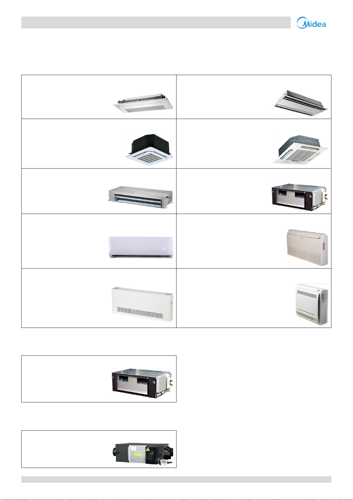
One-way Cassette
Two-way Cassette
Q1 Q2
Compact Four-way Cassette
Four-way Cassette
Q4C
Q4
Medium Static Pressure Duct
High Static Pressure Duct
T2 T1
Wall-mounted
Ceiling & Floor
G DL
Floor Standing
Console
F Z
Fresh Air Processing Unit
FA
Heat Recovery Ventilator
2 External Appearance
2.1 Indoor Units
2.1.1 Standard indoor units
Table 1-2.1: Standard indoor unit appearance
2.1.2 Fresh air processing unit
Table 1-2.2: Fresh air processing unit appearance
2.2 Heat Recovery Ventilator
Table 1-2.3: Heat recovery ventilator appearance
6
Page 8
V6-i VRF 50/60Hz
Part 1
- General Information
8/10/12HP
(with single fan)
14/16/18HP
(with single fan)
20/22HP
(with dual fans)
24/26/28/30/32HP
(with dual fans)
2.3 Outdoor Units
Table 1-2.4: Outdoor unit appearance
7
Page 9
V6-i VRF 50/60Hz
Midea V6-i Series Engineering Data Book
Type
Minimum
combination ratio
Maximum combination ratio
Standard indoor
units only
Fresh air processing
units only
Fresh air processing units and
standard indoor units together
V6-i Series outdoor units
50%
130%
100%
100%1
Outdoor unit capacity
Sum of capacity indexes of
connected indoor units (standard
indoor units only)
Sum of capacity indexes of connected indoor
units (fresh air processing units and standard
indoor units together)
Maximum number of
connected indoor
units
kW
HP
Capacity
index
25.2 8 252
126 to 327.6
126 to 252
13
28.0
10
280
140 to 364
140 to 280
16
33.5
12
335
167.5 to 435.5
167.5 to 335
20
40.0
14
400
200 to 520
200 to 400
23
45.0
16
450
225 to 585
225 to 450
26
50.0
18
500
250 to 650
250 to 500
29
56.0
20
560
280 to 728
280 to 560
33
61.5
22
615
307.5 to 799.5
307.5 to 615
36
67.0
24
670
335 to 871
335 to 670
39
73.0
26
730
365 to 949
365 to 730
43
78.5
28
785
392.5 to 1020.5
392.5 to 785
46
85.0
30
850
425 to 1105
425 to 850
50
90.0
32
900
450 to 1170
450 to 900
53
Combination ratio =
Sum of capacity indexes of the indoor units
Capacity index of the outdoor unit
3 Combination Ratio
Table 1-5.1: Indoor and outdoor unit combination ratio limitations
Notes:
1. When fresh air processing units are installed together with standard indoor units, the total capacity of the fresh air processing units must not exceed 30%
of the capacity of the outdoor unit and the combination ratio must not exceed 100%.
Table 1-5.2: Combinations of Indoor and outdoor units
8
Page 10

-i V6-i VRF 50/60Hz
Part 2
- Component Layout
and
Refrigerant Circuits
Part 2
Component Layout and
Refrigerant Circuits
1 Layout of Functional Components ....................................................... 10
2 Piping Diagrams .................................................................................. 16
3 Refrigerant Flow Diagrams .................................................................. 22
9
Page 11
V6-i VRF 50/60Hz
Midea V6-i Series Service Manual
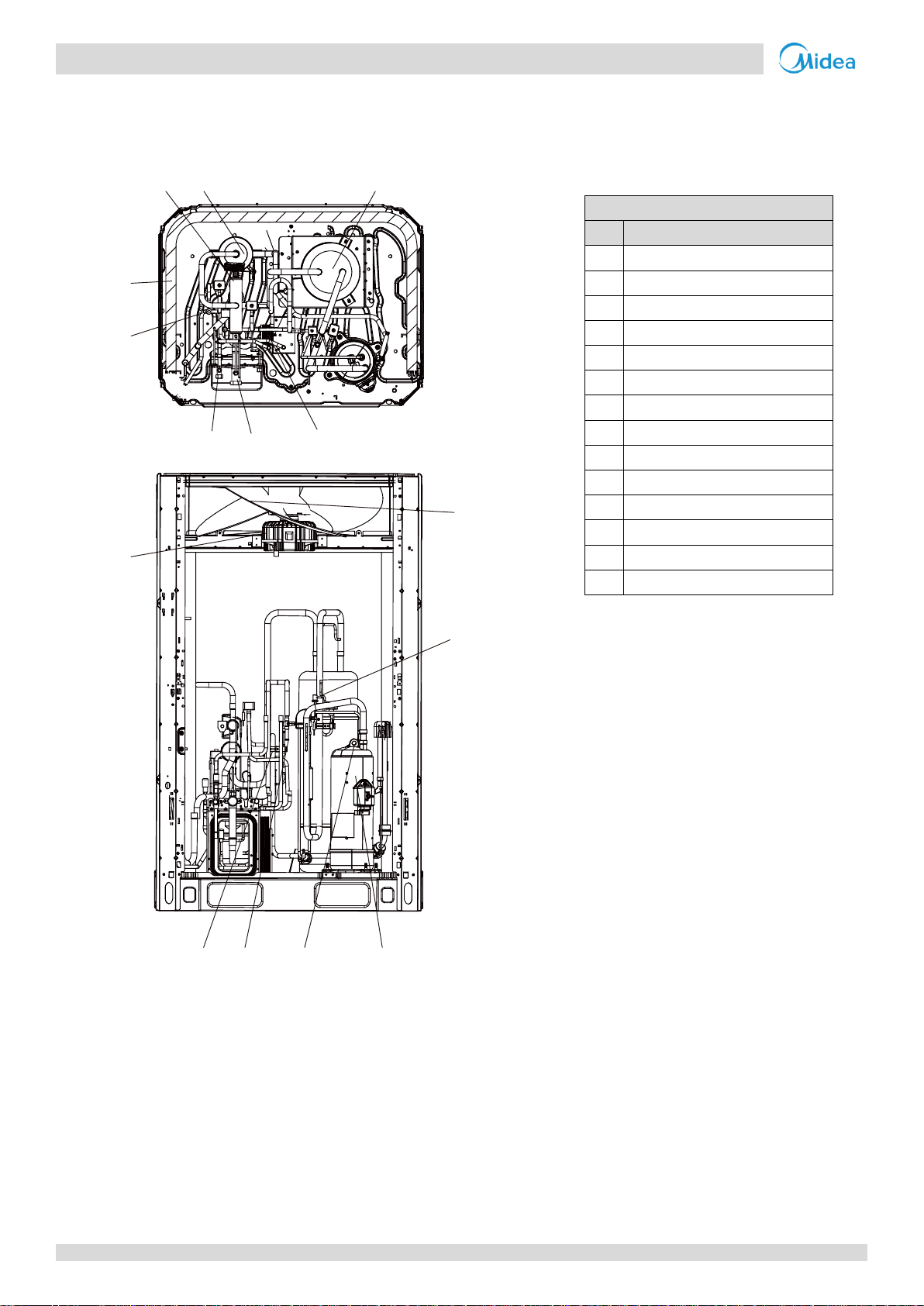
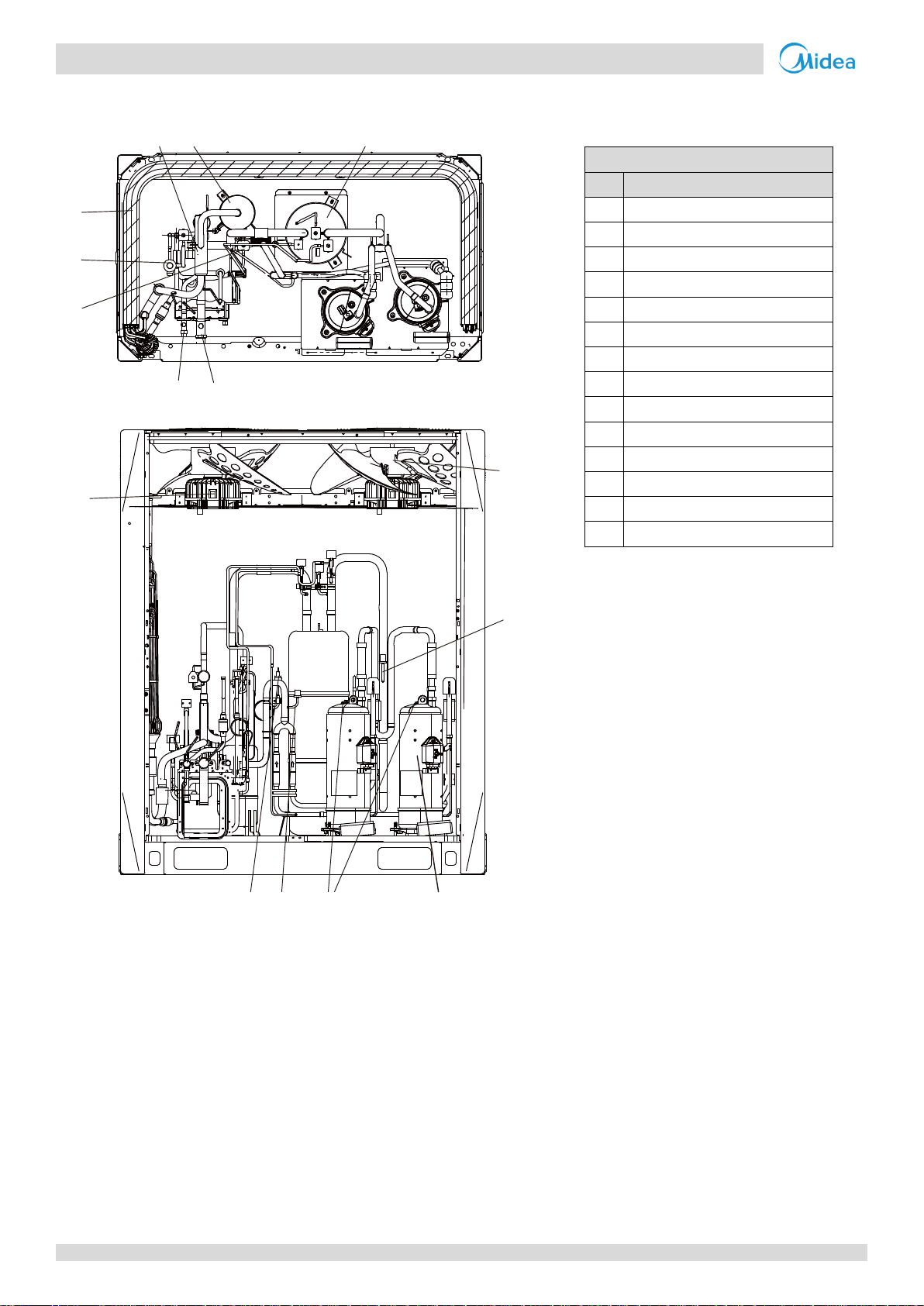
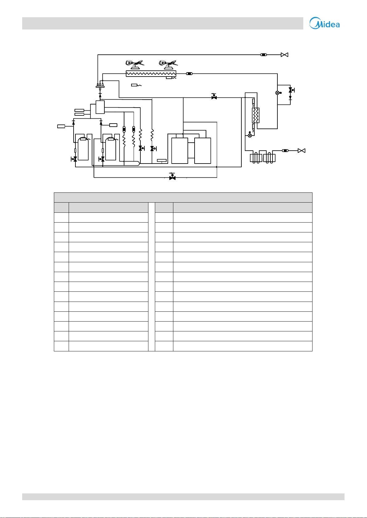
Legend
No.
Parts name
1
Compressor
2
Discharge temperature switch
3
High pressure switch
4
High pressure sensor
5
Oil separator
6
Four-way valve
7
Heat exchanger
8
Electronic expansion valve (EXV)
9
Low pressure switch
10
Fan motor
11
Fan
12
Stop valve (liquid side)
13
Stop valve (gas side)
14
Plate heat exchanger
15
56
7
8
12
13
14
11
9
10
3
4 2
1
1 Layout of Functional Components
8/10/12HP
Figure 2-1.1: 8/10/12 layout of functional components
10
Page 12
-i V6-i VRF 50/60Hz
Part 2
- Component Layout
and
Refrigerant Circuits
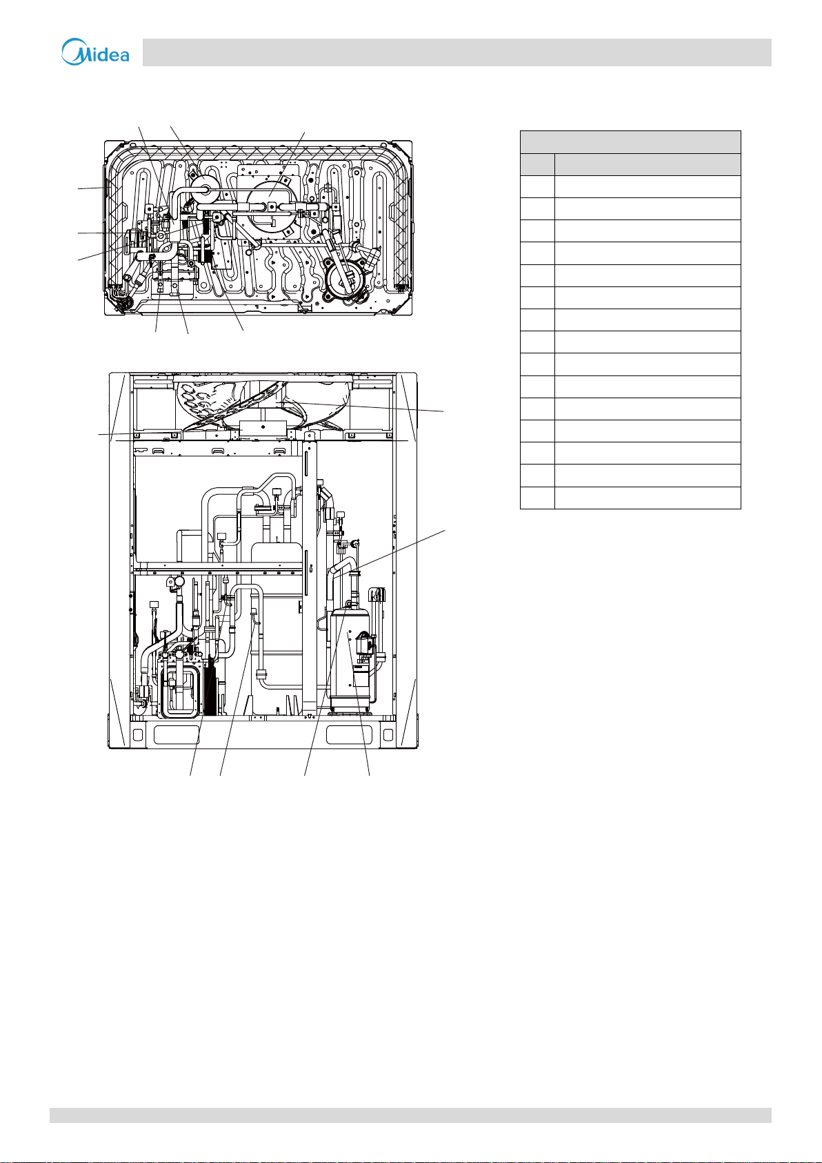
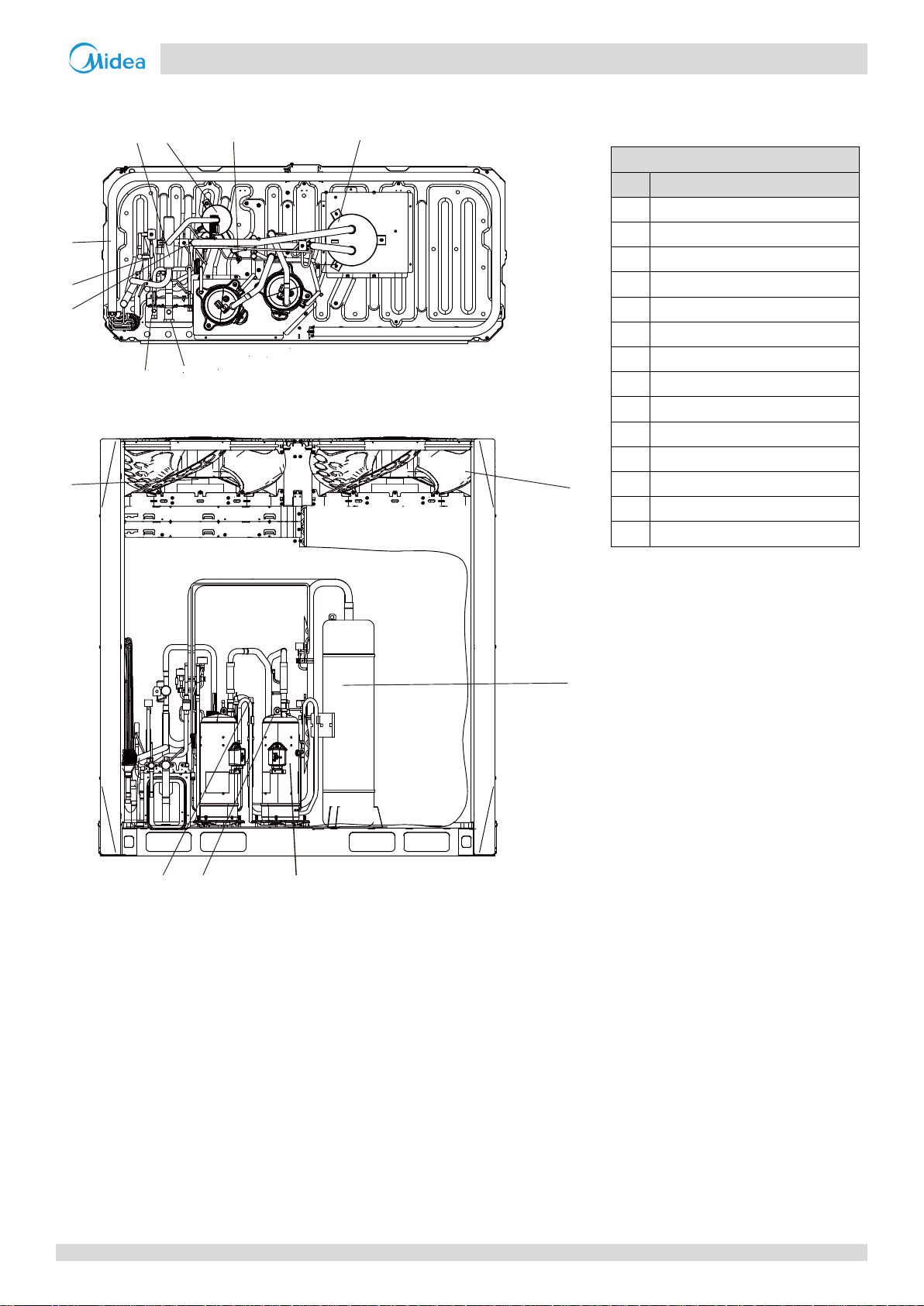
Legend
No.
Parts name
1
Compressor
2
Discharge temperature switch
3
High pressure switch
4
High pressure sensor
5
Oil separator
6
Four-way valve
7
Heat exchanger
8
Electronic expansion valve (EXV)
9
Low pressure switch
10
Fan motor
11
Fan
12
Stop valve (liquid side)
13
Stop valve (gas side)
14
Plate heat exchanger
15
Accumulator
15
5
6
7
8
9
12
13
14
11
9
10
3
4
2
1
14/16/18HP
Figure 2-1.2: 14/16/18 layout of functional components
11
Page 13
V6-i VRF 50/60Hz
Midea V6-i Series Service Manual
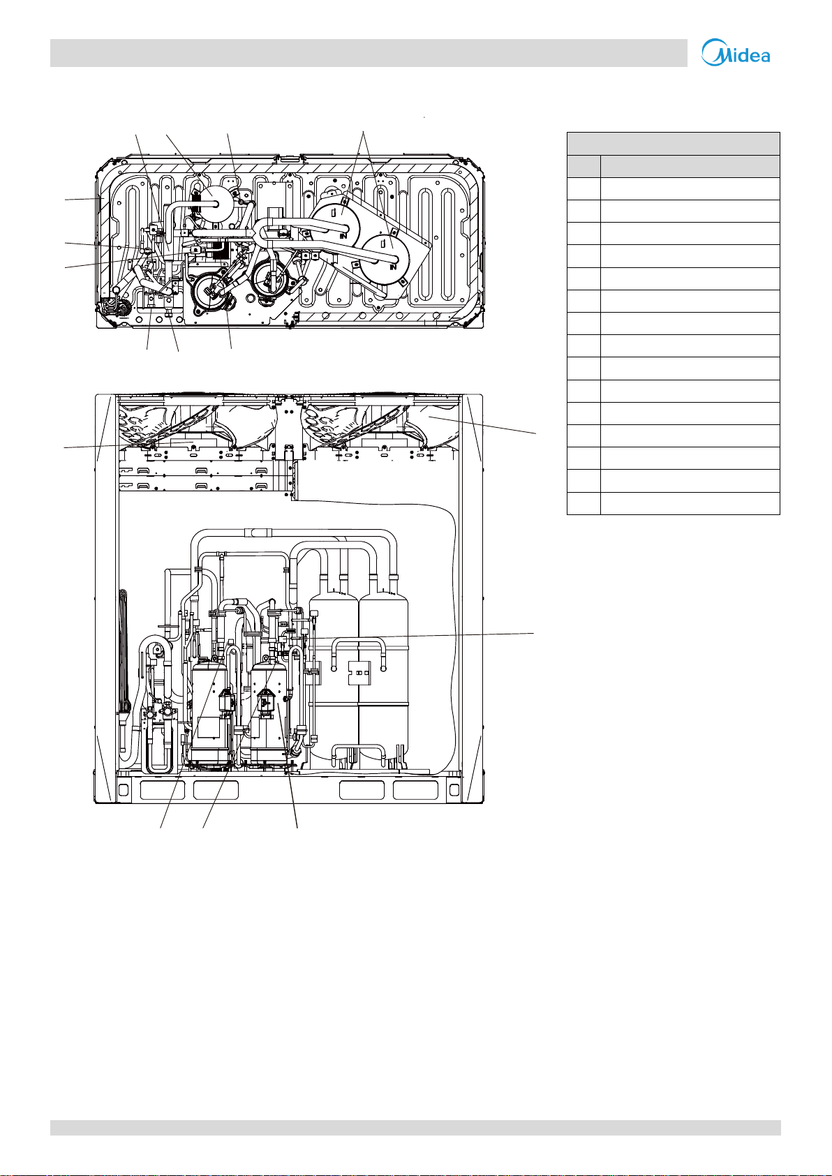
Legend
No.
Parts name
1
Compressor
2
Discharge temperature switch
3
High pressure switch
4
High pressure sensor
5
Oil separator
6
Four-way valve
7
Heat exchanger
8
Electronic expansion valve (EXV)
9
Low pressure switch
10
Fan motor
11
Fan
12
Stop valve (liquid side)
13
Stop valve (gas side)
15
Accumulator
1556
7
8
9
12
13
11
9
10
3
4
2
1
20/22HP
Figure 2-1.3: 20/22 layout of functional components
12
Page 14
-i V6-i VRF 50/60Hz
Part 2
- Component Layout
and
Refrigerant Circuits
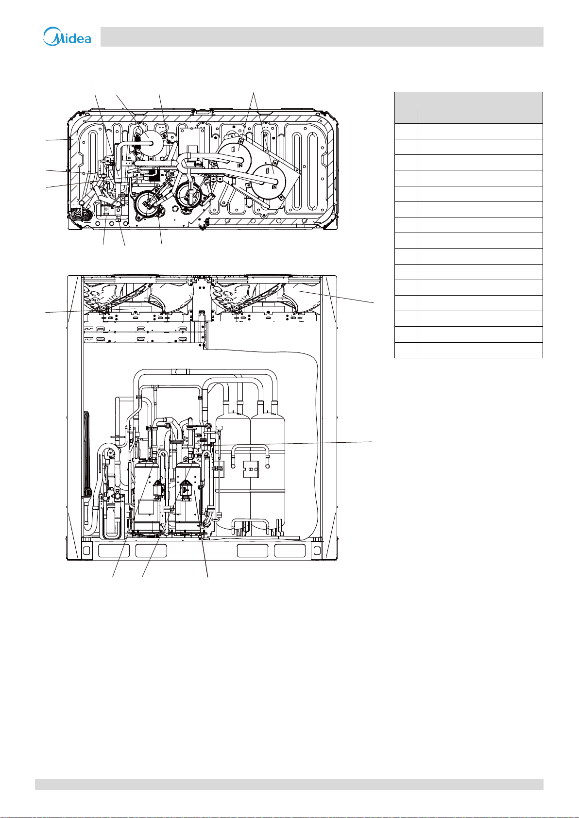
Legend
No.
Parts name
1
Compressor
2
Discharge temperature switch
3
High pressure switch
4
High pressure sensor
5
Oil separator
6
Four-way valve
7
Heat exchanger
8
Electronic expansion valve (EXV)
9
Low pressure switch
10
Fan motor
11
Fan
12
Stop valve (liquid side)
13
Stop valve (gas side)
15
Accumulator
15
5
4
6
7
8
9
12
13
11
9
10
3
2
1
24HP
Figure 2-1.4: 24 layout of functional components
13
Page 15
V6-i VRF 50/60Hz
Midea V6-i Series Service Manual
Legend
No.
Parts name
1
Compressor
2
Discharge temperature switch
3
High pressure switch
4
High pressure sensor
5
Oil separator
6
Four-way valve
7
Heat exchanger
8
Electronic expansion valve (EXV)
9
Low pressure switch
10
Fan motor
11
Fan
12
Stop valve (liquid side)
13
Stop valve (gas side)
14
Plate heat exchanger
15
Accumulator
15
5
4
6
7
8
9
12
13
14
11
9
10
3
2
1
26/28HP
Figure 2-1.5: 26/28 layout of functional components
14
Page 16
-i V6-i VRF 50/60Hz
Part 2
- Component Layout
and
Refrigerant Circuits
Legend
No.
Parts name
1
Compressor
2
Discharge temperature switch
3
High pressure switch
4
High pressure sensor
5
Oil separator
6
Four-way valve
7
Heat exchanger
8
Electronic expansion valve (EXV)
9
Low pressure switch
10
Fan motor
11
Fan
12
Stop valve (liquid side)
13
Stop valve (gas side)
14
Plate heat exchanger
15
Accumulator
15
5
4
6
7
8
9
12
13
14
11
9
10
3
2
1
30/32HP
Figure 2-1.6: 30/32 layout of functional components
15
Page 17
V6-i VRF 50/60Hz
Midea V6-i Series Service Manual
Legend
No.
Parts name
No.
Parts name
1
Compressor
14
Plate heat exchanger
2
Discharge temperature switch
15
Accumulator
3
High pressure switch
T3
Heat exchanger temperature sensor
4
High pressure sensor
T4
Outdoor ambient temperature sensor
5
Oil separator
T6A
Plate heat exchanger inlet temperature sensor
6
Four-way valve
T6B
Plate heat exchanger outlet temperature sensor
7
Heat exchanger
T7C1
Compressor A discharge temperature sensor
8
Electronic expansion valve (EXV)
T7C2
Compressor B discharge temperature sensor
9
Low pressure switch
SV4
Oil return valve
10
Fan motor
SV5
Fast defrosting (in heating) and unloading (in cooling) valve
11
Fan
SV6
Refrigerant bypass EXV valve
12
Stop valve (liquid side)
SV8A
Compressor A vapor injection valve
13
Stop valve (gas side)
7
1
15 12
9
3
2
4
5
6
11
10
14
8
8
13
EXVA
EXVC
E
S
C
T3
T4
T6B
T7C1
T7C2
T6A
SV8A
SV4
SV5
SV6
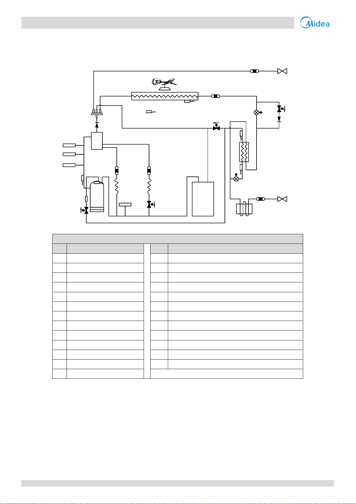
2 Piping Diagrams
8/10/12HP
Figure 2-2.1: 8/10/12HP piping diagram
16
Page 18
-i V6-i VRF 50/60Hz
Part 2
- Component Layout
and
Refrigerant Circuits
Legend
No.
Parts name
No.
Parts name
1
Compressor
14
Plate heat exchanger
2
Discharge temperature switch
15
Accumulator
3
High pressure switch
T3
Heat exchanger temperature sensor
4
High pressure sensor
T4
Outdoor ambient temperature sensor
5
Oil separator
T6A
Plate heat exchanger inlet temperature sensor
6
Four-way valve
T6B
Plate heat exchanger outlet temperature sensor
7
Heat exchanger
T7C1
Compressor A discharge temperature sensor
8
Electronic expansion valve (EXV)
T7C2
Compressor B discharge temperature sensor
9
Low pressure switch
SV4
Oil return valve
10
Fan motor
SV5
Fast defrosting (in heating) and unloading (in cooling) valve
11
Fan
SV6
Refrigerant bypass EXV valve
12
Stop valve (liquid side)
SV7
Refrigerant bypass indoor units valve
13
Stop valve (gas side)
SV8A
Compressor A vapor injection valve
1
15
12
9
3
4
5
6
11
10
7
14
8
8
13
EXVA
EXVC
E
S
C
SV8A
SV4
SV7
SV5
SV6
T3
T4
T6B
T6A
2
T7C1
T7C2
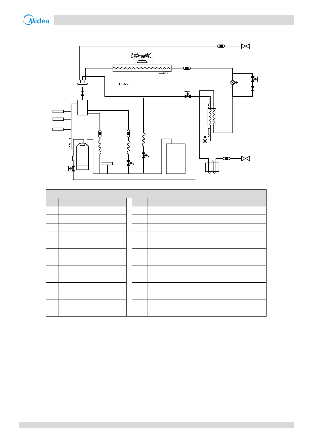
14/16/18HP
Figure 2-2.2: 14/16/18HP piping diagram
17
Page 19
V6-i VRF 50/60Hz
Midea V6-i Series Service Manual
Legend
No.
Parts name
No.
Parts name
1
Compressor
15
Accumulator
2
Discharge temperature switch
T3
Heat exchanger temperature sensor
3
High pressure switch
T4
Outdoor ambient temperature sensor
4
High pressure sensor
T6A
Plate heat exchanger inlet temperature sensor
5
Oil separator
T6B
Plate heat exchanger outlet temperature sensor
6
Four-way valve
T7C1
Compressor A discharge temperature sensor
7
Heat exchanger
T7C2
Compressor B discharge temperature sensor
8
Electronic expansion valve (EXV)
SV4
Oil return valve
9
Low pressure switch
SV5
Fast defrosting (in heating) and unloading (in cooling) valve
10
Fan motor
SV6
Refrigerant bypass EXV valve
11
Fan
SV8A
Compressor A vapor injection valve
12
Stop valve (liquid side)
SV8B
Compressor B vapor injection valve
13
Stop valve (gas side)
SV9
Compressor B pressure balance valve
14
Plate heat exchanger
7
1
1
15
12
9
3
4
5
6
11
11
10 10
8
13
EXVA
E
S
C
SV9
SV4
SV5
SV6
SV2
T3
T4
2
T7C1
T7C2
2
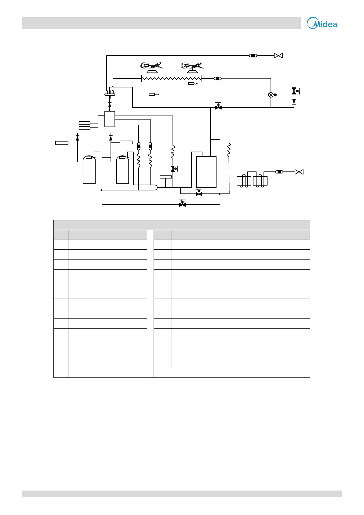
20/22/24HP
Figure 2-2.3: 20/22/24HP piping diagram
18
Page 20
-i V6-i VRF 50/60Hz
Part 2
- Component Layout
and
Refrigerant Circuits
Legend
No.
Parts name
No.
Parts name
1
Compressor
15
Accumulator
2
Discharge temperature switch
T3
Heat exchanger temperature sensor
3
High pressure switch
T4
Outdoor ambient temperature sensor
4
High pressure sensor
T6A
Plate heat exchanger inlet temperature sensor
5
Oil separator
T6B
Plate heat exchanger outlet temperature sensor
6
Four-way valve
T7C1
Compressor A discharge temperature sensor
7
Heat exchanger
T7C2
Compressor B discharge temperature sensor
8
Electronic expansion valve (EXV)
SV4
Oil return valve
9
Low pressure switch
SV5
Fast defrosting (in heating) and unloading (in cooling) valve
10
Fan motor
SV6
Refrigerant bypass EXV valve
11
Fan
SV8A
Compressor A vapor injection valve
12
Stop valve (liquid side)
SV8B
Compressor B vapor injection valve
13
Stop valve (gas side)
SV9
Compressor B pressure balance valve
14
Plate heat exchanger
7
1
1
15
15
12
9
3
4
5
6
11
10
11
10
14
8
8
SV6
13
EXVA
EXVC
S
E
C
SV8A
SV8B
SV4
SV9
SV5
T3
T4
T6B
T6A
T7C1
T7C2
2
2
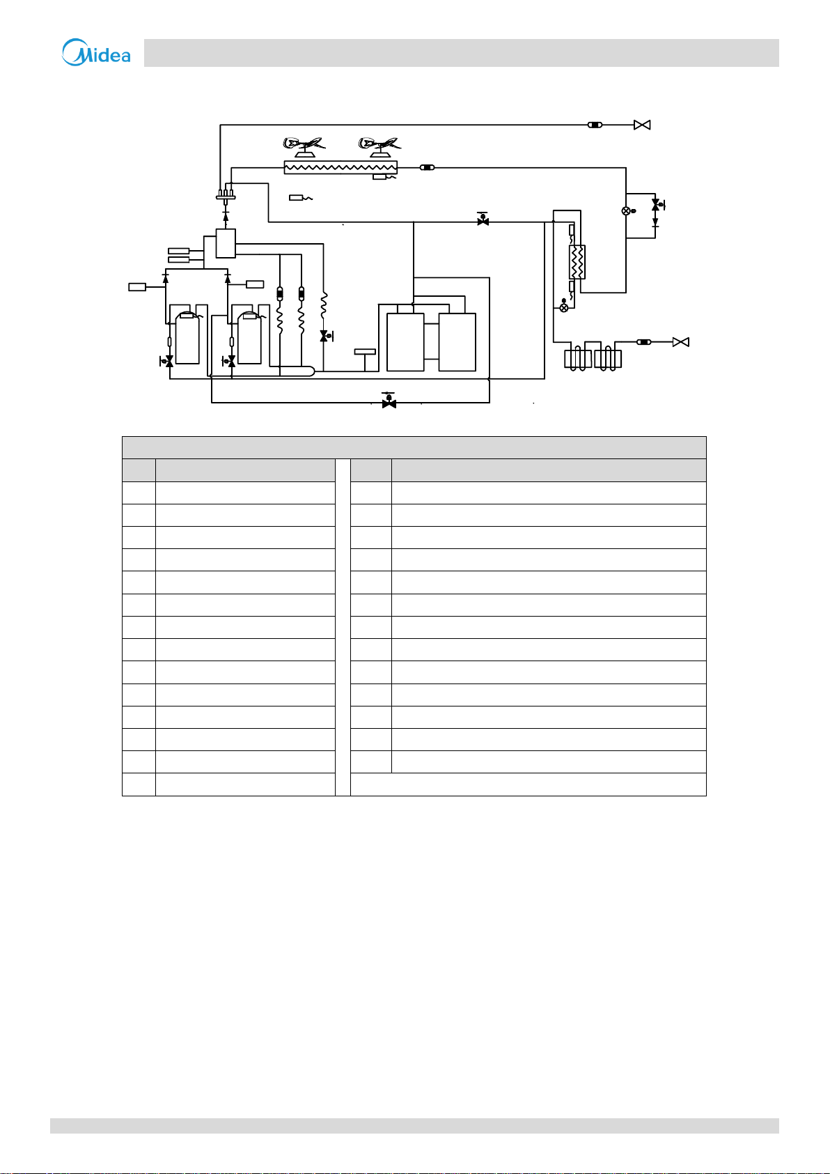
26/28HP
Figure 2-2.4: 26/28HP piping diagram
19
Page 21
V6-i VRF 50/60Hz
Midea V6-i Series Service Manual
Legend
No.
Parts name
No.
Parts name
1
Compressor
15
Accumulator
2
Discharge temperature switch
T3
Heat exchanger temperature sensor
3
High pressure switch
T4
Outdoor ambient temperature sensor
4
High pressure sensor
T6A
Plate heat exchanger inlet temperature sensor
5
Oil separator
T6B
Plate heat exchanger outlet temperature sensor
6
Four-way valve
T7C1
Compressor A discharge temperature sensor
7
Heat exchanger
T7C2
Compressor B discharge temperature sensor
8
Electronic expansion valve (EXV)
SV4
Oil return valve
9
Low pressure switch
SV5
Fast defrosting (in heating) and unloading (in cooling) valve
10
Fan motor
SV6
Refrigerant bypass EXV valve
11
Fan
SV7
Refrigerant bypass indoor units valve
12
Stop valve (liquid side)
SV8A
Compressor A vapor injection valve
13
Stop valve (gas side)
SV8B
Compressor B vapor injection valve
14
Plate heat exchanger
SV9
Compressor B pressure balance valve
7
1
1
15
15
12
9
3
4
5
6
11
10
11
10
14
8
8
13
EXVA
EXVC
E
S
C
SV6
SV5
SV9
S
V7
S
V4
SV8A
SV8B
T3
T4
T6B
T6A
T7C1
T7C2
2
2
30/32HP
Figure 2-2.5: 30/32HP piping diagram
20
Page 22

-i V6-i VRF 50/60Hz
Part 2
- Component Layout
and
Refrigerant Circuits
Key components:
1. Oil separator:
Separates oil from gas refrigerant pumped out of the compressor and quickly returns it to the compressor. Separation
efficiency is up to 99%.
2. Accumulator:
Stores liquid refrigerant and oil to protect compressor from liquid hammering.
3. Electronic expansion valve (EXV):
Controls refrigerant flow and reduces refrigerant pressure.
4. Four-way valve:
Controls refrigerant flow direction. Closed in cooling mode and open in heating mode. When closed, the heat
exchanger functions as a condenser; when open, the heat exchanger functions as an evaporator.
5. Solenoid valve SV4:
Returns oil to the compressor. Opens once the compressor has run for 200 seconds and closes 600 seconds later and
then opens for 3 minutes every 20 minutes.
6. Solenoid valve SV5:
Enables fast defrosting in heating mode and unloading in cooling mode. During defrosting operation, opens to
shorten the refrigerant flow cycle and quicken the defrosting process. In cooling mode, SV5 opens when outdoor
ambient temperature is above 40oC or compressor frequency is below 41Hz.
7. Solenoid valve SV6:
Allows refrigerant to bypass the expansion valves. Opens in cooling mode when discharge temperature exceeds the
limit. Closed in heating mode and standby.
8. Solenoid valve SV7:
Allows refrigerant to return directly to the compressor. Opens when indoor air temperature is close to the set
temperature to avoid frequent compressor on/off.
9. Solenoid valve SV8A / SV8B:
Allows refrigerant from plate heat exchanger inject directly to the compressor. SV8A opens when compressor A
startup and closes when compressor A stop. SV8B delays opening when compressor B startup and closes when
compressor B stop.
10. Solenoid valve SV9:
Balances compressor B pressure. Opens before compressor B startup and closed after compressor B running for 15
seconds. Opens after compressor B stops 10s and keep opening 60s.
11. High and low pressure switches:
Regulate system pressure. When system pressure rises above the upper limit or falls below the lower limit, the high or
low pressure switches turn off, stopping the compressor. After 10 minutes, the compressor restarts.
21
Page 23
V6-i VRF 50/60Hz
Midea V6-i Series Service Manual
7
1
15
12
9
3
2
4
5
6
11
10
14
8
13
EXVA
EXVC
E
S
C
T3
T4
T6B
T7C1
T7C2
T6A
SV8A
SV4
SV5
SV6
Closed
Filter
Filter
Closed
Unit on
Thermostat off
Unit on
Thermostat on
Unit on
Thermostat on
Unit off
Filter
Indoor unit operation
Filter
Normal control
Filter
Filter
Normal control
Filter
Filter
High temperature, high pressure gas
High temperature, high pressure liquid
Medium temperature, medium pressure gas
Low temperature, low pressure
Fan
on
Fan
off
Fan
on
Fan
on
7
1
15
12
9
3
2
4
5
6
11
10
14
8
13
High temperature, high pressure gas
High temperature, high pressure liquid
Medium temperature, medium pressure gas
Low temperature, low pressure
EXVA
EXVC
E
S
C
T3
T4
T6B
T7C1
T7C2
T6A
SV8A
SV4
SV5
SV6
300 steps
Filter
Filter
300 steps
Unit on
Thermostat off
Unit on
Thermostat on
Unit on
Thermostat on
Unit off
Filter
Indoor unit operation
Filter
Normal control
Filter
Filter
Normal control
Filter
Filter
Fan
on
Fan
off
Fan
on
Fan
on
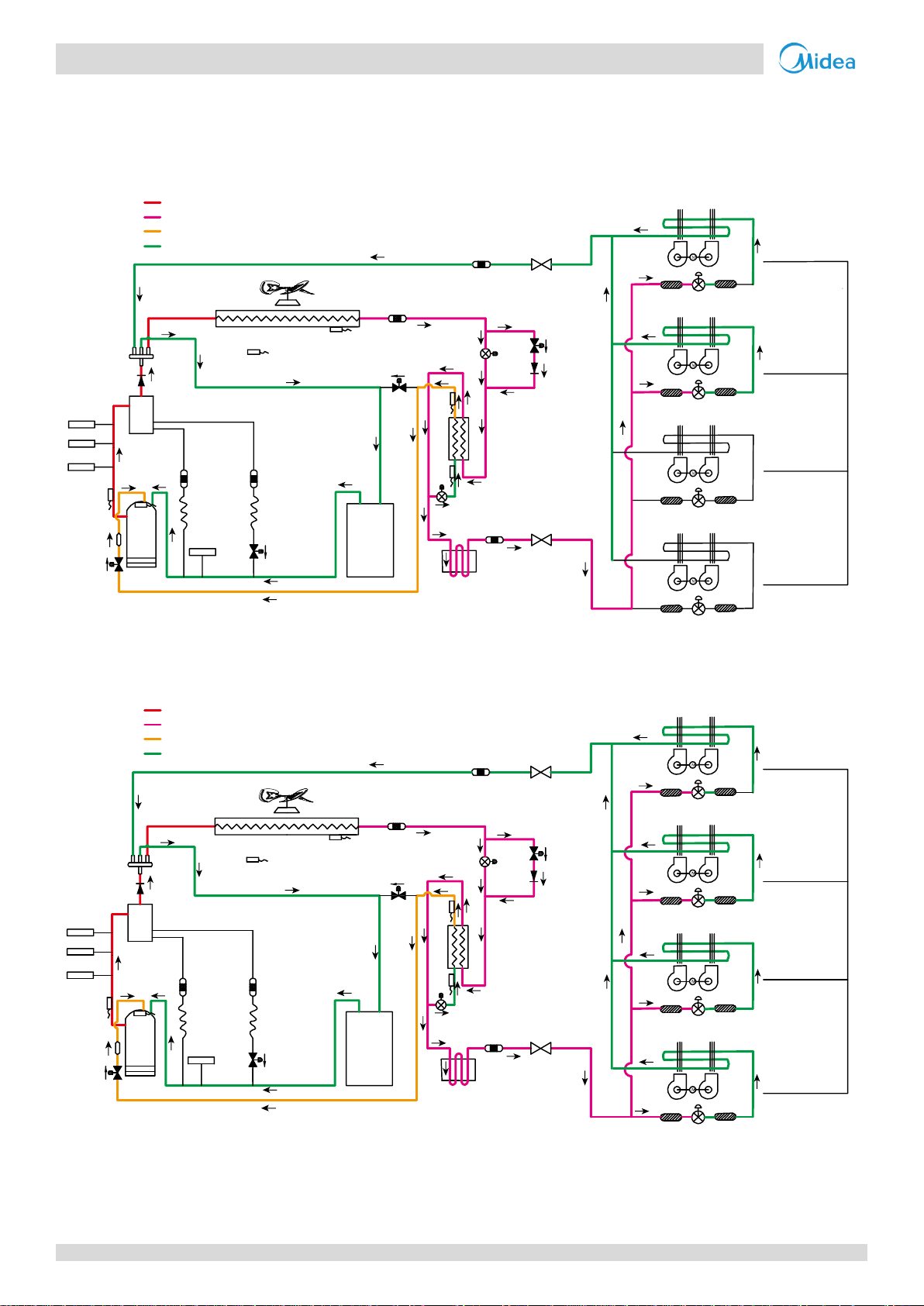
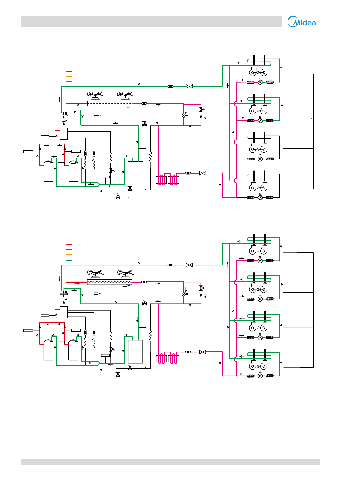
3 Refrigerant Flow Diagrams
8/10/12HP
Cooling operation
Figure 2-3.1: 8/10/12HP refrigerant flow during cooling operation
Oil return operation in cooling mode
Figure 2-3.2: 8/10/12HP refrigerant flow during oil return operation in cooling mode
22
Page 24
-i V6-i VRF 50/60Hz
Part 2
- Component Layout
and
Refrigerant Circuits
7
1
15
12
9
3
2
4
5
6
11
10
14
8
13
High temperature, high pressure gas
High temperature, high pressure liquid
Medium temperature, medium pressure gas
Low temperature, low pressure
EXVA
EXVC
E
S
C
T3
T4
T6B
T7C1
T7C2
T6A
SV8A
SV4
SV5
SV6
480 steps
Filter
Filter
480 steps
Unit on
Thermostat off
Unit on
Thermostat on
Unit on
Thermostat on
Unit off
Filter
Indoor unit operation
Filter
480 steps
Filter
Filter
480 steps
Filter
Filter
Fan
off
Fan
off
Fan
off
Fan
off
High temperature, high pressure gas
High temperature, high pressure liquid
Medium temperature, medium pressure gas
Low temperature, low pressure
7
1
15
12
9
3
2
4
5
6
11
10
14
8
13
EXVA
EXVC
E
S
C
T3
T4
T6B
T7C1
T7C2
T6A
SV8A
SV4
SV5
SV6
Closed
Closed
Filter
Filter
Unit on
Thermostat off
Unit on
Thermostat on
Unit on
Thermostat on
Unit off
Filter
Indoor unit operation
Filter
Normal control
Normal control
Filter
Filter
Filter
Filter
Fan
on
Fan
off
Fan
on
Fan
on
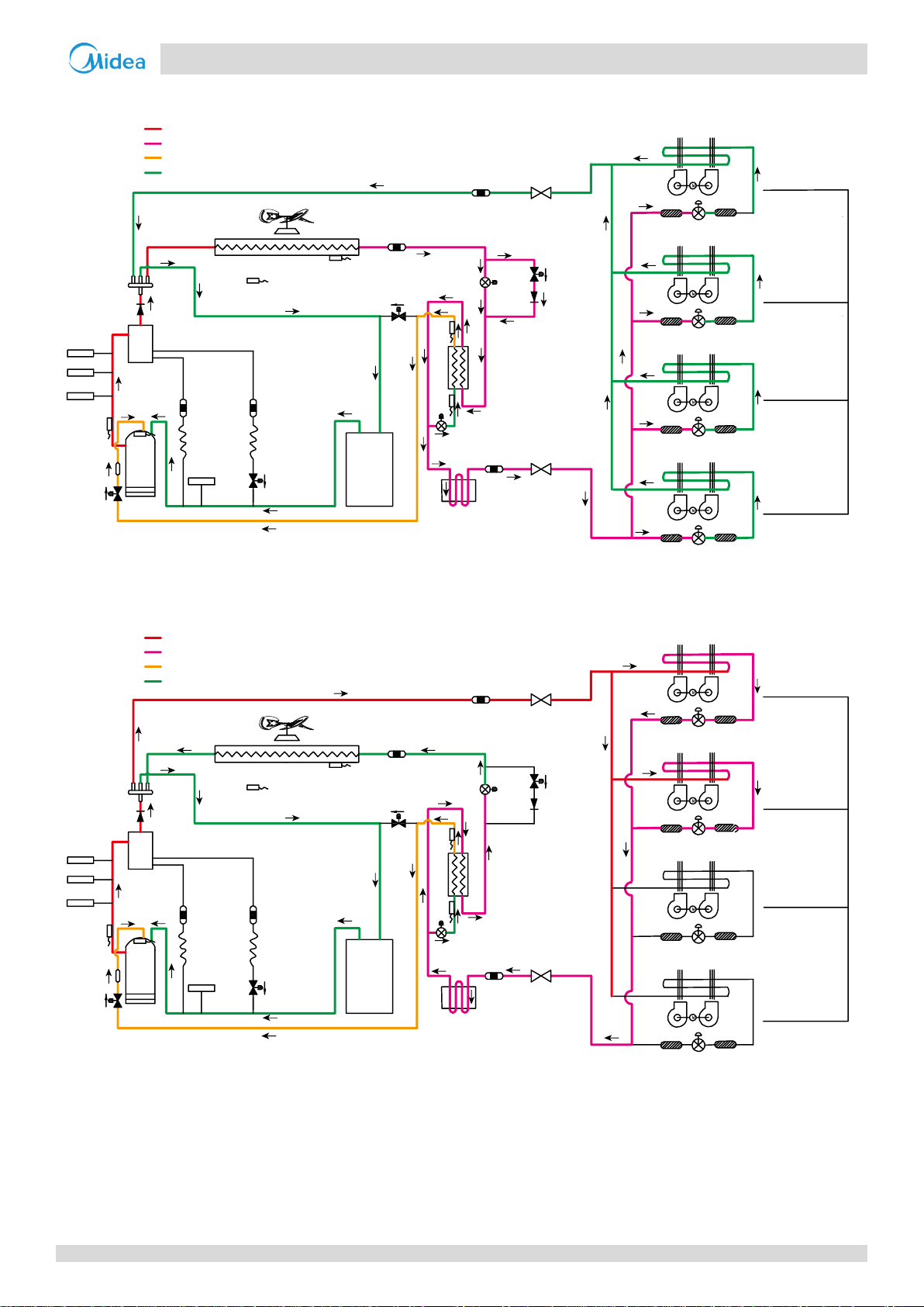
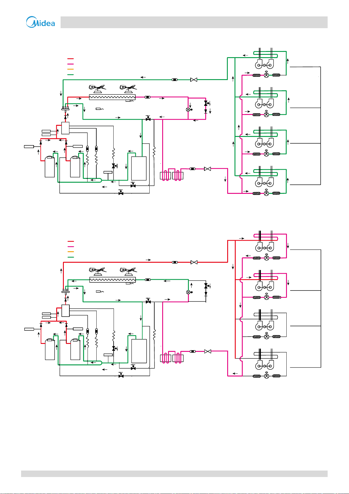
Oil return operation in heating mode and defrosting operation
Figure 2-3.3: 8/10/12HP refrigerant flow during oil return operation in heating mode and during defrosting operation
Heating operation
Figure 2-3.4: 8/10/12HP refrigerant flow during heating operation
23
Page 25
V6-i VRF 50/60Hz
Midea V6-i Series Service Manual
SV7
7
1
15
12
9
3
2
4
5
6
11
10
14
13
EXVC
E
S
C
T3
T4
T6B
T7C1
T7C2
T6A
SV8A
SV4
SV5
High temperature, high pressure gas
High temperature, high pressure liquid
Medium temperature, medium pressure gas
Low temperature, low pressure
EXVA
8
SV6
Closed
Filter
Filter
Closed
Unit on
Thermostat off
Unit on
Thermostat on
Unit on
Thermostat on
Unit off
Filter
Indoor unit operation
Filter
Normal control
Filter
Filter
Normal control
Filter
Filter
Fan
on
Fan
off
Fan
on
Fan
on
SV7
EXVA
8
SV6
7
1
15
12
9
5
6
11
10
14
13
High temperature, high pressure gas
High temperature, high pressure liquid
Medium temperature, medium pressure gas
Low temperature, low pressure
EXVC
E
S
C
T3
T4
T6B
T7C1
T7C2
T6A
SV8A
SV4
SV5
300 steps
Filter
Filter
300 steps
Unit on
Thermostat off
Unit on
Thermostat on
Unit on
Thermostat on
Unit off
Filter
Indoor unit operation
Filter
Normal control
Filter
Filter
Normal control
Filter
Filter
Fan
on
Fan
off
Fan
on
Fan
on
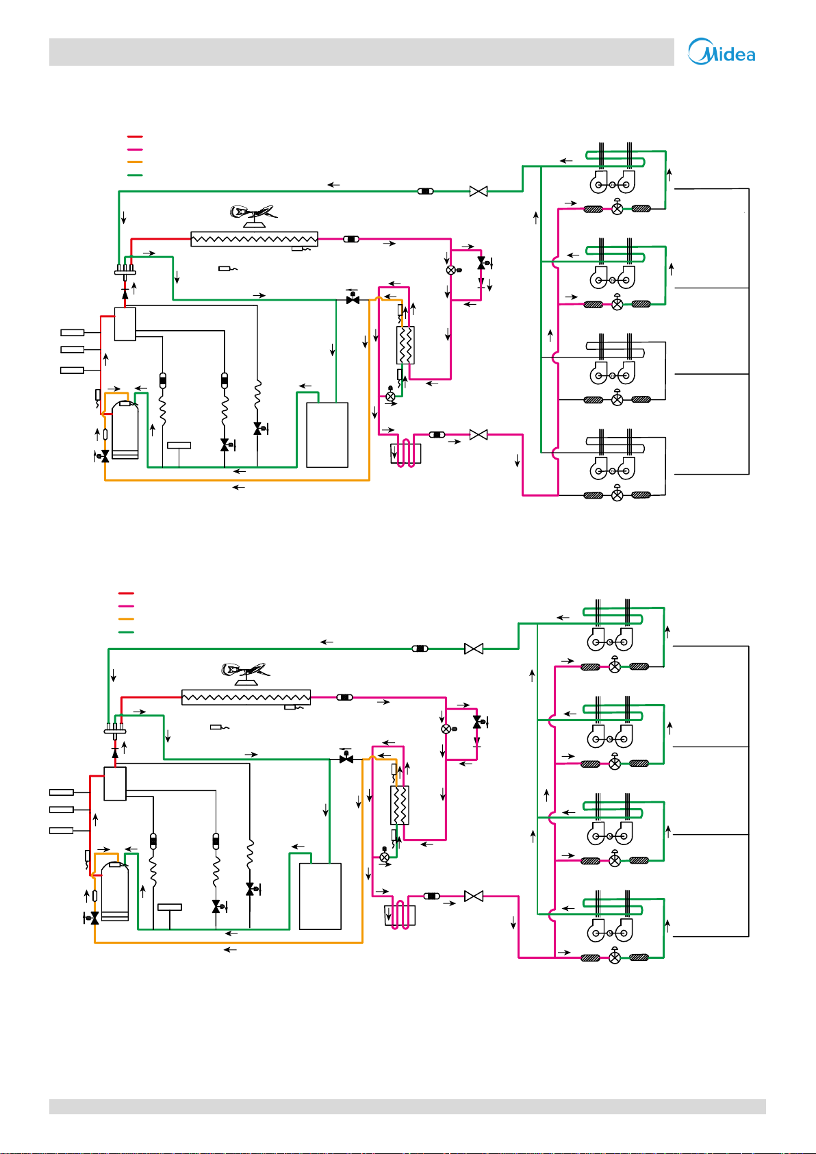
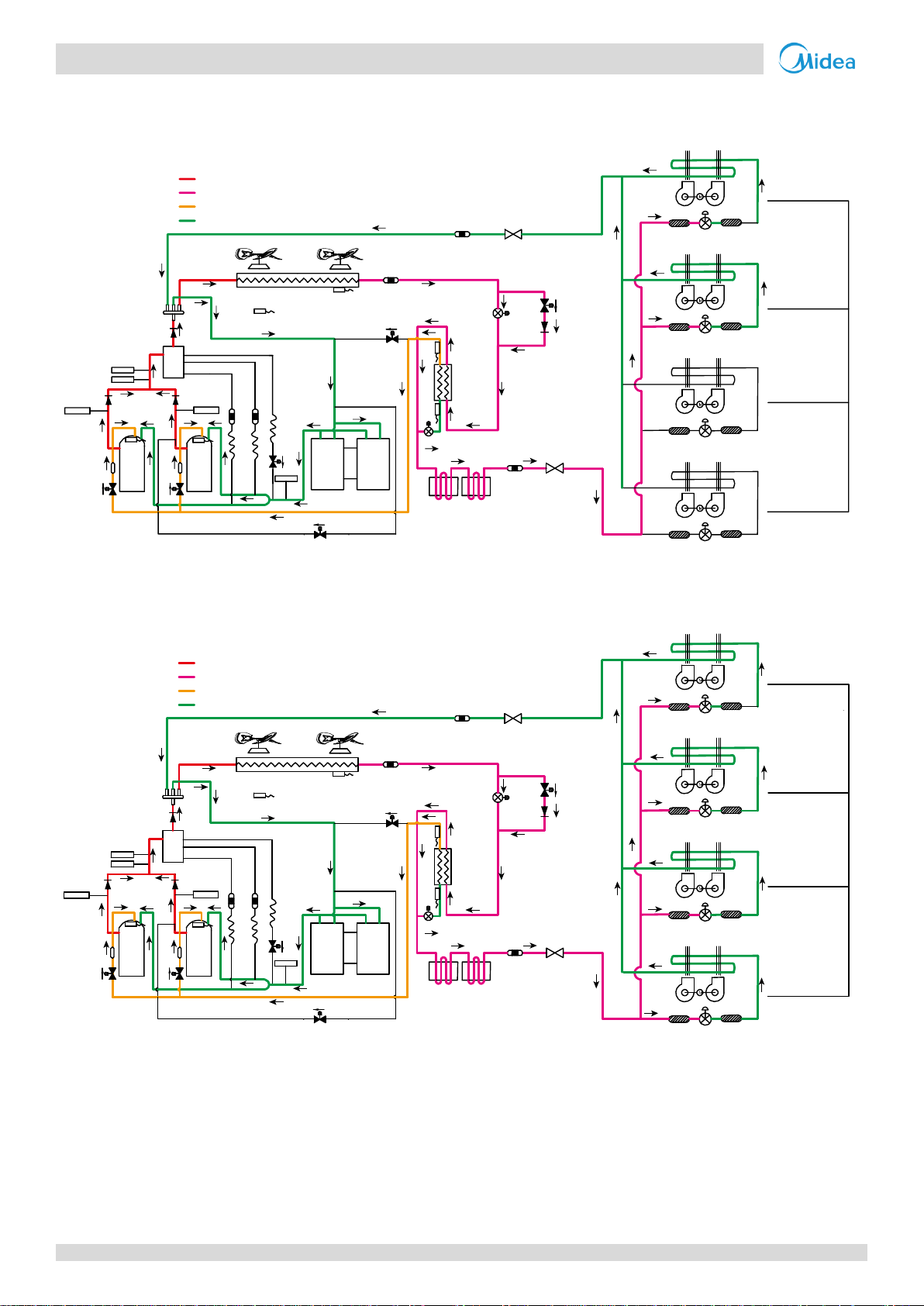
14/16/18HP
Cooling operation
Figure 2-3.5: 14/16/18 refrigerant flow during cooling operation
Oil return operation in cooling mode
Figure 2-3.6: 14/16/18HP refrigerant flow during oil return operation in cooling mode
24
Page 26

-i V6-i VRF 50/60Hz
Part 2
- Component Layout
and
Refrigerant Circuits
SV7
EXVA
8
SV6
7
1
15
12
9
3
2
4
5
6
11
10
14
13
High temperature, high pressure gas
High temperature, high pressure liquid
Medium temperature, medium pressure gas
Low temperature, low pressure
EXVC
E
S
C
T3
T4
T6B
T7C1
T7C2
T6A
SV8A
SV4
SV5
480 steps
Filter
Filter
480 steps
Unit on
Thermostat off
Unit on
Thermostat on
Unit on
Thermostat on
Unit off
Filter
Indoor unit operation
Filter
480 steps
Filter
Filter
480 steps
Filter
Filter
Fan
off
Fan
off
Fan
off
Fan
off
SV7
EXVA
8
SV6
High temperature, high pressure gas
High temperature, high pressure liquid
Medium temperature, medium pressure gas
Low temperature, low pressure
7
1
15
12
9
3
2
4
5
6
11
10
14
13
EXVC
E
S
C
T3
T4
T6B
T7C1
T7C2
T6A
SV8A
SV4
SV5
Closed
Closed
Filter
Filter
Unit on
Thermostat off
Unit on
Thermostat on
Unit on
Thermostat on
Unit off
Filter
Indoor unit operation
Filter
Normal control
Normal control
Filter
Filter
Filter
Filter
Fan
on
Fan
off
Fan
on
Fan
on
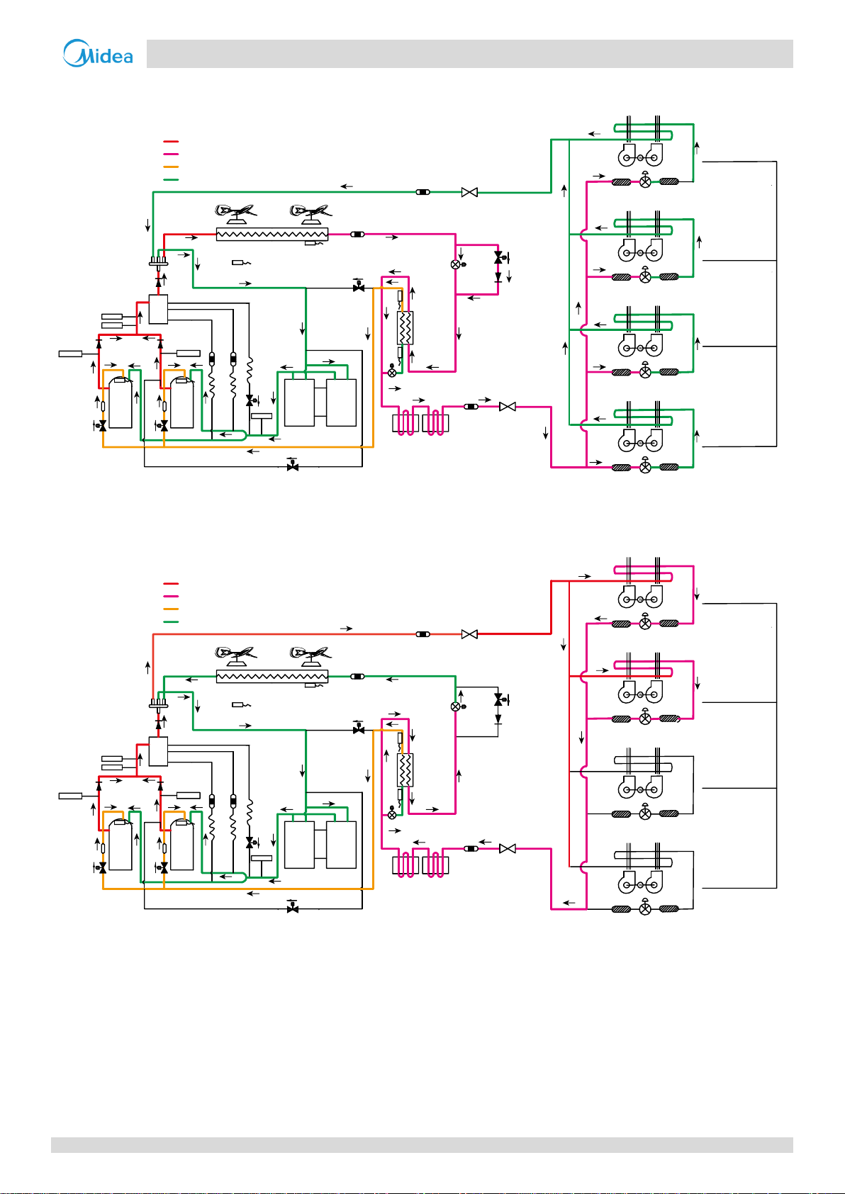
Oil return operation in heating mode and defrosting operation
Figure 2-3.7: 14/16/18HP refrigerant flow during oil return operation in heating mode and during defrosting operation
Heating operation
Figure 2-3.8: 14/16/18HP refrigerant flow during heating operation
25
Page 27
V6-i VRF 50/60Hz
Midea V6-i Series Service Manual
7
1
1
159
3
4
5
6
11
11
10 10
8
13
EXVA
E
S
C
T3
T4
2
T7C1
T7C2
SV9
SV4
SV5
SV6
2
High temperature, high pressure gas
High temperature, high pressure liquid
Medium temperature, medium pressure gas
Low temperature, low pressure
Closed
Filter
Filter
Closed
Unit on
Thermostat off
Unit on
Thermostat on
Unit on
Thermostat on
Unit off
Filter
Indoor unit operation
Filter
Normal control
Filter
Filter
Normal control
Filter
Filter
Fan
on
Fan
off
Fan
on
Fan
on
12
SV2
300 steps
Filter
Filter
300 steps
Unit on
Thermostat off
Unit on
Thermostat on
Unit on
Thermostat on
Unit off
Filter
Indoor unit operation
Filter
Normal control
Filter
Filter
Normal control
Filter
Filter
Fan
on
Fan
off
Fan
on
Fan
on
7
1
1
159
3
4
5
6
11
11
10 10
8
13
EXVA
E
S
C
T3
T4
2
T7C1
T7C2
SV9
SV4
SV5
SV6
2
High temperature, high pressure gas
High temperature, high pressure liquid
Medium temperature, medium pressure gas
Low temperature, low pressure
12
SV2
20/22/24HP
Cooling operation
Figure 2-3.9: 20/22/24 refrigerant flow during cooling operation
Oil return operation in cooling mode
Figure 2-3.10: 20/22/24HP refrigerant flow during oil return operation in cooling mode
26
Page 28
-i V6-i VRF 50/60Hz
Part 2
- Component Layout
and
Refrigerant Circuits
480 steps
Filter
Filter
480 steps
Unit on
Thermostat off
Unit on
Thermostat on
Unit on
Thermostat on
Unit off
Filter
Indoor unit operation
Filter
480 steps
Filter
Filter
480 steps
Filter
Filter
Fan
off
Fan
off
Fan
off
Fan
off
7
1
1
159
3
4
5
6
11
11
10 10
8
13
EXVA
E
S
C
T3
T4
2
T7C1
T7C2
SV9
SV4
SV5
SV6
2
High temperature, high pressure gas
High temperature, high pressure liquid
Medium temperature, medium pressure gas
Low temperature, low pressure
12
SV2
Closed
Closed
Filter
Filter
Unit on
Thermostat off
Unit on
Thermostat on
Unit on
Thermostat on
Unit off
Filter
Indoor unit operation
Filter
Normal control
Normal control
Filter
Filter
Filter
Filter
Fan
on
Fan
off
Fan
on
Fan
on
7
1
1
159
3
4
5
6
11
11
10 10
8
13
EXVA
E
S
C
T3
T4
2
T7C1
T7C2
SV9
SV4
SV5
SV6
2
High temperature, high pressure gas
High temperature, high pressure liquid
Medium temperature, medium pressure gas
Low temperature, low pressure
12
SV2
Oil return operation in heating mode and defrosting operation
Figure 2-3.11: 20/22/24HP refrigerant flow during oil return operation in heating mode and during defrosting operation
Heating operation
Figure 2-3.12: 20/22/24HP refrigerant flow during heating operation
27
Page 29
V6-i VRF 50/60Hz
Midea V6-i Series Service Manual
15
15
7
1
1
12
9
3
4
5
6
11
11
10 10
14
8
8
13
EXVA
EXVC
E
S
C
T3
T4
2
T7C1
T7C2
T6B
T6A
SV8A
SV8B
SV9
SV4
SV5
SV6
2
High temperature, high pressure gas
High temperature, high pressure liquid
Medium temperature, medium pressure gas
Low temperature, low pressure
Closed
Filter
Filter
Closed
Unit on
Thermostat off
Unit on
Thermostat on
Unit on
Thermostat on
Unit off
Filter
Indoor unit operation
Filter
Normal control
Filter
Filter
Normal control
Filter
Filter
Fan
on
Fan
off
Fan
on
Fan
on
300 steps
Filter
Filter
300 steps
Unit on
Thermostat off
Unit on
Thermostat on
Unit on
Thermostat on
Unit off
Filter
Indoor unit operation
Filter
Normal control
Filter
Filter
Normal control
Filter
Filter
Fan
on
Fan
off
Fan
on
Fan
on
15
15
7
1
1
12
9
3
4
5
6
11
11
10 10
14
8
8
13
EXVA
EXVC
E
S
C
T3
T4
2
T7C1
T7C2
T6B
T6A
SV8A
SV8B
SV9
SV4
SV5
SV6
2
High temperature, high pressure gas
High temperature, high pressure liquid
Medium temperature, medium pressure gas
Low temperature, low pressure
26/28HP
Cooling operation
Figure 2-3.13: 26/28 refrigerant flow during cooling operation
Oil return operation in cooling mode
Figure 2-3.14: 26/28HP refrigerant flow during oil return operation in cooling mode
28
Page 30
-i V6-i VRF 50/60Hz
Part 2
- Component Layout
and
Refrigerant Circuits
480 steps
Filter
Filter
480 steps
Unit on
Thermostat off
Unit on
Thermostat on
Unit on
Thermostat on
Unit off
Filter
Indoor unit operation
Filter
480 steps
Filter
Filter
480 steps
Filter
Filter
Fan
off
Fan
off
Fan
off
Fan
off
15
15
7
1
1
12
9
3
4
5
6
11
11
10 10
14
8
8
13
EXVA
EXVC
E
S
C
T3
T4
2
T7C1
T7C2
T6B
T6A
SV8A
SV8B
SV9
SV4
SV5
SV6
2
High temperature, high pressure gas
High temperature, high pressure liquid
Medium temperature, medium pressure gas
Low temperature, low pressure
Closed
Closed
Filter
Filter
Unit on
Thermostat off
Unit on
Thermostat on
Unit on
Thermostat on
Unit off
Filter
Indoor unit operation
Filter
Normal control
Normal control
Filter
Filter
Filter
Filter
Fan
on
Fan
off
Fan
on
Fan
on
15
15
7
1
1
12
9
3
4
5
6
11
11
10 10
14
8
8
13
EXVA
EXVC
E
S
C
T3
T4
2
T7C1
T7C2
T6B
T6A
SV8A
SV8B
SV9
SV4
SV5
SV6
2
High temperature, high pressure gas
High temperature, high pressure liquid
Medium temperature, medium pressure gas
Low temperature, low pressure
Oil return operation in heating mode and defrosting operation
Figure 2-3.15: 26/28HP refrigerant flow during oil return operation in heating mode and during defrosting operation
Heating operation
Figure 2-3.16: 26/28HP refrigerant flow during heating operation
29
Page 31

V6-i VRF 50/60Hz
Midea V6-i Series Service Manual
15
15
7
1
1
12
3
4
5
6
11
11
10 10
14
8
8
13
EXVA
EXVC
E
S
C
T3
T4
2
T7C1
T7C2
T6B
T6A
SV8A
SV8B
SV9
SV4
SV5
SV6
2
High temperature, high pressure gas
High temperature, high pressure liquid
Medium temperature, medium pressure gas
Low temperature, low pressure
Closed
Filter
Filter
Closed
Unit on
Thermostat off
Unit on
Thermostat on
Unit on
Thermostat on
Unit off
Filter
Indoor unit operation
Filter
Normal control
Filter
Filter
Normal control
Filter
Filter
Fan
on
Fan
off
Fan
on
Fan
on
9
S
V7
300 steps
Filter
Filter
300 steps
Unit on
Thermostat off
Unit on
Thermostat on
Unit on
Thermostat on
Unit off
Filter
Indoor unit operation
Filter
Normal control
Filter
Filter
Normal control
Filter
Filter
Fan
on
Fan
off
Fan
on
Fan
on
15
15
7
1
1
12
3
4
5
6
11
11
10 10
14
8
8
13
EXVA
EXVC
E
S
C
T3
T4
2
T7C1
T7C2
T6B
T6A
SV8A
SV8B
SV9
SV4
SV5
SV6
2
High temperature, high pressure gas
High temperature, high pressure liquid
Medium temperature, medium pressure gas
Low temperature, low pressure
9
S
V7
30/32HP
Cooling operation
Figure 2-3.17: 30/32 refrigerant flow during cooling operation
Oil return operation in cooling mode
Figure 2-3.18: 30/32HP refrigerant flow during oil return operation in cooling mode
30
Page 32

-i V6-i VRF 50/60Hz
Part 2
- Component Layout
and
Refrigerant Circuits
480 steps
Filter
Filter
480 steps
Unit on
Thermostat off
Unit on
Thermostat on
Unit on
Thermostat on
Unit off
Filter
Indoor unit operation
Filter
480 steps
Filter
Filter
480 steps
Filter
Filter
Fan
off
Fan
off
Fan
off
Fan
off
15
15
7
1
1
12
3
4
5
6
11
11
10 10
14
8
8
13
EXVA
EXVC
E
S
C
T3
T4
2
T7C1
T7C2
T6B
T6A
SV8A
SV8B
SV9
SV4
SV5
SV6
2
High temperature, high pressure gas
High temperature, high pressure liquid
Medium temperature, medium pressure gas
Low temperature, low pressure
9
S
V7
Closed
Closed
Filter
Filter
Unit on
Thermostat off
Unit on
Thermostat on
Unit on
Thermostat on
Unit off
Filter
Indoor unit operation
Filter
Normal control
Normal control
Filter
Filter
Filter
Filter
Fan
on
Fan
off
Fan
on
Fan
on
15
15
7
1
1
12
3
4
5
6
11
11
10 10
14
8
8
13
EXVB
EXVC
E
S
C
T3
T4
2
T7C1
T7C2
T6B
T6A
SV8A
SV8B
SV9
SV4
SV5
SV6
2
High temperature, high pressure gas
High temperature, high pressure liquid
Medium temperature, medium pressure gas
Low temperature, low pressure
9
S
V7
Oil return operation in heating mode and defrosting operation
Figure 2-3.19: 30/32HP refrigerant flow during oil return operation in heating mode and during defrosting operation
Heating operation
Figure 2-3.20: 30/32HP refrigerant flow during heating operation
31
Page 33

V6-i VRF 50/60Hz
Midea V6-i Series Service Manual
32
Page 34

V6-i VRF 50/60Hz
Part 3
- Control
Part 3
Control
1 General Control Scheme Flowchart ...................................................... 34
2 Stop Operation .................................................................................... 35
3 Standby Control ................................................................................... 35
4 Startup Control .................................................................................... 36
5 Normal Operation Control ................................................................... 38
6 Protection Control ............................................................................... 43
7 Special Control ..................................................................................... 45
33
Page 35

V6-i VRF 50/60Hz
Midea V6-i Series Service Manual
Legend
Numbers in the top right-hand
corners of boxes indicate the
relevant section of text on the
following pages.
Conditions met
for oil return
Conditions met
for defrosting
Thermo on
Special control
Outdoor unit duty cycling
Oil return operation
Defrosting operation
7
Stop operation
A unit stops when the load demanded decreases
2
Standby control
Crankcase heater control
3
Startup control
Startup control for heating operation
4
Thermo on
Normal operation control
Outdoor fan control
5
Protection control
Compressor and inverter module protection
Disable heating control
6
1 General Control Scheme Flowchart
Sections 3-2 to 3-7 on the following pages detail when each of the controls in the flowchart below is activated.
Abnormal shutdown
System stops
Compressor startup delay control
Startup control for cooling operation
Component control during normal operation
Compressor output control
Compressor step control
Operation priority and rotation of compressors
Electronic expansion valve control
High pressure protection control
Low pressure protection control
Discharge temperature protection control
control
34
Page 36

V6-i VRF 50/60Hz
Part 3
- Control
Figure 3-3.1: Crankcase heater controlled according to outdoor ambient temperature
Figure 3-3.2: Crankcase heater controlled according to discharge temperature
Ambient temperature < 35 oC
Ambient temperature > 40 oC
Crankcase heater off
Crankcase heater is controlled according to discharge temperature
Discharge temperature < 40 oC
Discharge temperature > 50 oC
Crankcase heater off
Crankcase heater on
2 Stop Operation
The stop operation occurs for one of the three following reasons:
1. Abnormal shutdown: in order to protect the compressors, if an abnormal state occurs the system makes a 'stop with
thermo off' operation and an error code is displayed on the outdoor unit digital displays.
2. The system stops when the set temperature has been reached.
3 Standby Control
3.1 Crankcase Heater Control
The crankcase heater is used to prevent refrigerant from mixing with compressor oil when the compressors are stopped.
The crankcase heater is controlled according to outdoor ambient temperature and discharge temperature. When the
outdoor ambient temperature is above 40°C, the crankcase heater is off; when the outdoor ambient temperature is below
35°C, the crankcase heater is controlled according to discharge temperature. Refer to Figures 3-3.1 and 3-3.2.
35
Page 37

V6-i VRF 50/60Hz
Midea V6-i Series Service Manual
Component
Wiring
diagram
label
8-12HP
14-18HP
20-24HP
26-28HP
30-32HP
Control functions and states
Inverter compressor A
COMP(A)
● ● ● ● ●
Controlled according to load requirement,
operating frequency increased by 1 step / sec
Inverter compressor B
COMP(B)
● ● ●
DC fan motor A
FANA
● ● ● ● ●
Fan speed1 controlled according to discharge
pressure (Pc):
At initial speed for 90 seconds.
Subsequently, P
c
checked every 10
seconds:
P
c
≥ 2.7MPa => 1 step increase.
P
c
≤ 2.1MPa => 1 step decrease.
DC fan motor B
FANB
● ● ●
Electronic expansion
valve A
EXVA
● ● ● ● ●
Position (steps) from 0 (fully closed) to 480 or
3000 (fully open), controlled according to
discharge temperature
Electronic expansion
valve C
EXVC
● ● ● ● ●
Position (steps) from 0 (fully closed) to 480
(fully open), controlled according to
temperature different between plate heat
exchanger inlet and outlet
Four-way valve
ST1
● ● ● ● ●
Off
Solenoid valve (oil
balance)
SV4
● ● ● ● ●
Closed for 200 secs, open for 600 secs, then
closed
Solenoid valve (fast
defrosting (in cooling)
and unloading (in
heating))
SV5
● ● ● ● ●
Open for 4 mins, then closed
Solenoid valve (EXV
bypass)
SV6
● ● ● ● ●
Open for 10 mins, then controlled according
to pressure
Solenoid valve (indoor
units bypass)
SV7
●
●
Controlled according to load requirement
Solenoid valve
(inverter compressor A
vapor injection)
SV8A
● ● ● ●
Controlled according to inverter compressor
A
Solenoid valve
(inverter compressor B
vapor injection)
SV8B
● ●
Controlled according to inverter compressor
B
Solenoid valve
(inverter compressor B
pressure balance)
SV9
● ● ●
Open before compressor B startup
Notes:
1. Refer to Table 3-5.3 in Part 3, 5.6 “Outdoor Fan Control” for more information on fan speed steps.
4 Startup Control
4.1 Compressor Startup Delay Control
In initial startup control, compressor startup is delayed for 12 minutes in order to let the outdoor unit search for the indoor
units’ addresses. In restart control (except in oil return operation and defrosting operation), compressor startup is delayed
such that a minimum of 7 minutes has elapsed since the compressor stopped, in order to prevent frequent compressor
on/off and to equalize the pressure within the refrigerant system.
4.2 Startup Control for Cooling Operation
Table 3-4.1: Component control during startup in cooling mode
36
Page 38

V6-i VRF 50/60Hz
Part 3
- Control
Component
Wiring
diagram
label
8-12HP
14-18HP
20-24HP
26-28HP
30-32HP
Control functions and states
Inverter compressor A
COMP(A)
● ● ● ● ●
Controlled according to load requirement,
operating frequency increased by 1 step /
sec
Inverter compressor B
COMP(B)
● ● ●
DC fan motor A
FANA
● ● ● ● ●
Open once the four-way valve has opened,
controlled according to outdoor ambient
temperature and load requirement
DC fan motor B
FANB
● ● ●
Electronic expansion
valve A
EXVA
● ● ● ● ●
Position (steps) from 0 (fully closed) to 480
or 3000 (fully open), controlled according
to discharge superheat
Electronic expansion
valve C
EXVC
● ● ● ● ●
Position (steps) from 0 (fully closed) to 480
(fully open), controlled according to
temperature different between plate heat
exchanger inlet and outlet
Four-way valve
ST1
● ● ● ● ●
On
Solenoid valve (oil
balance)
SV4
● ● ● ● ●
Closed for 200 secs, open for 600 secs, then
closed
Solenoid valve (fast
defrosting (in cooling)
and unloading (in
heating))
SV5
● ● ● ● ●
Open for 4 mins, then closed
Solenoid valve (EXV
bypass)
SV6
● ● ● ● ●
Off
Solenoid valve (indoor
units bypass)
SV7
●
●
Controlled according to load requirement
Solenoid valve (inverter
compressor A vapor
injection)
SV8A
● ● ● ●
Controlled according to inverter
compressor A
Solenoid valve (inverter
compressor B vapor
injection)
SV8B
● ●
Controlled according to inverter
compressor B
Solenoid valve (inverter
compressor B pressure
balance)
SV9
● ● ●
Open before compressor B startup
4.3 Startup Control for Heating Operation
Table 3-4.2: Component control during startup in heating mode
37
Page 39

V6-i VRF 50/60Hz
Midea V6-i Series Service Manual
Component
Wiring
diagram
label
8-12HP
14-18HP
20-24HP
26-28HP
30-32HP
Control functions and states
Inverter compressor A
COMP(A)
● ● ● ● ●
Controlled according to load requirement
Inverter compressor B
COMP(B)
● ● ●
DC fan motor A
FANA
● ● ● ● ●
Controlled according to discharge pressure
DC fan motor B
FANB
● ● ●
Electronic expansion
valve A
EXVA
● ● ● ● ●
Position (steps) from 0 (fully closed) to 480
or 3000 (fully open), controlled according to
discharge temperature
Electronic expansion
valve C
EXVC
● ● ● ● ●
Position (steps) from 0 (fully closed) to 480
(fully open), controlled according to
temperature different between plate heat
exchanger inlet and outlet
Four-way valve
ST1
● ● ● ● ●
On
Solenoid valve (oil
balance)
SV4
● ● ● ● ●
Open regularly
Solenoid valve (fast
defrosting (in cooling)
and unloading (in
heating))
SV5
● ● ● ● ●
Controlled according to ambient
temperature, discharge pressure, discharge
temperature, compressor running
frequency and discharge superheat
Solenoid valve (EXV
bypass)
SV6
● ● ● ● ●
Controlled according to discharge pressure
and discharge temperature
Solenoid valve (indoor
units bypass)
SV7
●
●
Controlled according to load requirement
Solenoid valve (inverter
compressor A vapor
injection)
SV8A
● ● ● ● ●
Controlled according to inverter compressor
A on/off
Solenoid valve (inverter
compressor B vapor
injection)
SV8B
● ●
Controlled according to inverter compressor
B on/off
Solenoid valve (inverter
compressor B pressure
balance)
SV9
● ● ●
Open before compressor B startup and close
after compressor B running for 15 seconds.
Open after compressor B stop 10 seconds
and keep open 60 seconds.
5 Normal Operation Control
5.1 Component Control during Normal Operation
Table 3-5.1: Component control during normal cooling operation
38
Page 40

V6-i VRF 50/60Hz
Part 3
- Control
Component
Wiring
diagram
label
8-12HP
14-18HP
20-24HP
26-28HP
30-32HP
Control functions and states
Inverter compressor A
COMP(A)
● ● ● ● ●
Controlled according to load requirement
Inverter compressor B
COMP(B)
● ● ●
DC fan motor A
FANA
● ● ● ● ●
Controlled according to outdoor ambient
temperature, outdoor heat exchanger pipe
temperature, discharge pressure and load
requirement
DC fan motor B
FANB
● ● ●
Electronic expansion
valve A
EXVA
● ● ● ● ●
Position (steps) from 0 (fully closed) to 480
or 3000 (fully open), controlled according to
discharge superheat
Electronic expansion
valve C
EXVC
● ● ● ● ●
Position (steps) from 0 (fully closed) to 480
(fully open), controlled according to
temperature different between plate heat
exchanger inlet and outlet
Four-way valve
ST1
● ● ● ● ●
On
Solenoid valve (oil
balance)
SV4
● ● ● ● ●
Open regularly
Solenoid valve (fast
defrosting (in cooling)
and unloading (in
heating))
SV5
● ● ● ● ●
Controlled according to ambient
temperature, discharge pressure, discharge
temperature, compressor running
frequency and discharge superheat
Solenoid valve (EXV
bypass)
SV6
● ● ● ● ●
Off
Solenoid valve (indoor
units bypass)
SV7
●
●
Controlled according to load requirement
Solenoid valve (inverter
compressor A vapor
injection)
SV8A
● ● ● ●
Controlled according to inverter compressor
A on/off
Solenoid valve (inverter
compressor B vapor
injection)
SV8B
● ●
Controlled according to inverter compressor
B on/off
Solenoid valve (inverter
compressor B pressure
balance)
SV9
● ● ●
Open before compressor B startup and close
after compressor B running for 15 seconds.
Open after compressor B stop 10 seconds
and keep open 60 seconds.
Table 3-5.2: Component control during heating operation
39
Page 41

V6-i VRF 50/60Hz
Midea V6-i Series Service Manual
Figure 3-5.1: Compressor priority and rotation – one outdoor unit
BP
No. 1
BP1
No. 1 No. 2
BP2
5.2 Compressor Output Control
The compressor rotation speed is controlled according to the load requirement. Before compressor startup, the outdoor
unit first estimates the indoor unit load requirement according to the nominal capacity of indoor units currently running,
and then correct for ambient temperature. The compressors then start up according to the corrected load requirement.
During operation the compressors are controlled according to the nominal capacity of indoor units currently running and
the indoor unit heat exchanger temperatures.
5.3 Compressor Step Control
The running speed of the compressors in rotations per second (rps) is one third of the frequency (in Hz) of the electrical
input to the compressor motors. The compressor speed can be altered in increments of 1 rps.
5.4 Operating Priority and Rotation of Compressors
Figures 3-5.1 shows the compressor operating priority and rotation in the outdoor unit. In units with two compressors,
inverter compressor A (BP1) operates in priority to inverter compressor B (BP2).
40
Page 42

V6-i VRF 50/60Hz
Part 3
- Control
Fan speed index
Fan speed (rpm)
8-18HP
20-22HP
24-32HP
FANA / FANB
FANA / FANB
0 0 0 / 0
0 / 0
1
120
150 / 0
120 / 0
2
150
190 / 0
150 / 0
3
170
230 / 0
170 / 0
4
190
270 / 0
190 / 0
5
210
310 / 0 (150 / 150)
210 / 0
6
230
350 / 0 (180 / 180)
230 / 0
7
250
380 / 0 (210 / 210)
250 / 0 (120 / 120)
8
270
410 / 0 (240 / 240)
270 / 0 ( 150 / 150)
9
290
280 / 280
330 / 0 (170 / 170)
10
310
320 / 320
370 / 0 (190 / 190)
11
330
360 / 360
210 / 210
12
350
400 / 400
230 / 230
13
370
440 / 440
250 / 250
14
390
480 / 480
270 / 270
15
410
520 / 520
290 / 290
16
430
560 / 560
310 / 310
17
450
600 / 600
330 / 330
18
470
640 / 640
350 / 350
19
490
680 / 680
370 / 370
20
510
720 / 720
400 / 400
21
530
760 / 760
430 / 430
22
560
800 / 800
470 / 470
5.5 Electronic Expansion Valve Control
EXVA control
The position of electronic expansion valves EXVA is controlled in steps from 0 (fully closed) to 480 (fully open) or 3000
(fully open).
In cooling mode:
When the outdoor unit is in standby:
EXVA is at position 352 (steps) or 2112 (steps).
When the outdoor unit is running:
EXVA is controlled according to discharge temperature.
In heating mode:
When the outdoor unit is in standby:
EXVA is at position 352 (steps) or 2112 (steps).
When the outdoor unit is running:
EXVA is controlled according to discharge superheat.
EXVC control
The positions of electronic expansion valves EXVC are controlled in steps from 0 (fully closed) to 480 (fully open).
In cooling / heating mode:
When the outdoor unit is in standby:
EXVC is fully closed.
When the outdoor unit is running:
EXVC is controlled according to temperature different between plate heat exchanger inlet and outlet.
5.6 Outdoor Fan Control
The speed of the outdoor unit fans is adjusted in steps, as shown in Table 3-5.3.
Table 3-5.3: Outdoor fan speed steps
41
Page 43

V6-i VRF 50/60Hz
Midea V6-i Series Service Manual
23
580
840 / 840
510 / 510
24
600
880 / 880
550 / 550
25
630
910 / 910
600 / 600
26
650
940 / 940
650 / 650
27
700
980 / 980
700 / 700
28
750
1010 / 1010
750 / 750
29
800
1020 / 1020
800 / 800
30
850
1050 / 1050
830 / 830
31
880
1080 / 1080
850 / 850
32
920
1120 / 1120
870 / 870
33
920
1140 / 1140
890 / 890
34
920
1140 / 1140
920 / 920
35
920
1140 / 1140
920 / 920
36 (ESP 40Pa mode)
950
1200 / 1200
950 / 950
37 (ESP 60Pa mode)
980
1200 / 1200
980 / 980
Note:
1. For 20-22HP unit fan speed 5 to 8 and 24-32HP unit fan speed 7 to 10, when fan speed decreases, the fan speed is shown in the bracket; when fan speed
increases, the fan speed is shown without bracket.
42
Page 44

V6-i VRF 50/60Hz
Part 3
- Control
Figure 3-6.1: High pressure protection control
Notes:
1. P
c
: Discharge pressure
Figure 3-6.2: Low pressure protection control
Notes:
1. P
e
: Suction pressure
Figure 3-6.3: Discharge temperature protection control
When P2 protection occurs 3 times
in 60 minutes, the H5 error is
displayed. When an H5 error occurs,
a manual system restart is required
before the system can resume
operation.
Pc > 4.4MPa
Pc < 3.2MPa
Normal operation
High pressure protection, error code P1 is displayed
Pe < 0.05MPa
Pe > 0.15MPa
Normal operation
Low pressure protection, error code P2 is displayed
120oC
100oC
90oC
Discharge temperature
Compressor off
90oC
6 Protection Control
6.1 High Pressure Protection Control
This control protects the system from abnormally high pressure and protects the compressors from transient spikes in
pressure.
6.2 Low Pressure Protection Control
This control protects the system from abnormally low pressure and protects the compressors from transient drops in
pressure.
6.3 Discharge Temperature Protection Control
This control protects the compressors from abnormally high temperatures and transient spikes in temperature. It is
performed for each compressor.
When the discharge temperature rises above 120°C the system displays P4 protection and all units stop running. When P4
protection occurs 3 times in 100 minutes, the H6 error is displayed. When an H6 error occurs, a manual system restart is
required before the system can resume operation.
43
Page 45

V6-i VRF 50/60Hz
Midea V6-i Series Service Manual
Figure 3-6.4: Compressor current protection control
Compressor model
AA55PHDG –D1YG
DC80PHDG –D1YG
Current
max
24.6
33
Figure 3-6.5: Inverter module temperature protection control
Notes:
1. T
f
: Heat sink temperature
Figure 3-6.6: Disable heating control
When PL protection occurs 3 times
in 100 minutes, the C7 error is
displayed. When a C7 error occurs, a
manual system restart is required
before the system can resume
operation.
Current ≥ Current
max
Current < Current
max
Normal operation
Compressor current protection, error code xP3 is displayed
Tf > 75oC
Tf < 73oC
Normal operation
Compressor output reduced
Tf > 80oC
Tf < 65oC
Inverter module temperature protection,
error code PL is displayed
Outdoor ambient temperature > 25oC
Outdoor ambient temperature < 23oC
Heating operation
Units stop
6.4 Compressor and Inverter Module Protection Control
This control protects the compressors from abnormally high currents and protects the inverter modules from abnormally
high temperatures. It is performed for each compressor and inverter module.
6.5 Disable Heating Control
When the outdoor ambient temperature rises above 25°C heating mode is disabled to prevent the mechanical load on
compressors becoming too high and to prevent low compression ratios which can result in insufficient compressor internal
oil lubrication.
44
Page 46

V6-i VRF 50/60Hz
Part 3
- Control
Table 3-7.1: Outdoor unit component control during oil return operation in cooling mode
Component
Wiring
diagram label
8-12HP
14-18HP
20-24HP
26-28HP
30-32HP
Control functions and states
Inverter compressor A
COMP(A)
● ● ● ● ●
Fixed frequency
Inverter compressor B
COMP(B)
● ● ●
DC fan motor A
FANA
● ● ● ● ●
Fan speed controlled according
to discharge pressure
DC fan motor B
FANB
● ● ●
Electronic expansion valve A
EXVA
● ● ● ● ●
Position 480 (steps) or 3000
(steps)
Electronic expansion valve C
EXVC
● ● ● ● ●
Position 96 (steps)
Four-way valve
ST1
● ● ● ● ●
Off
Solenoid valve (oil balance)
SV4
● ● ● ● ●
Normal control
Solenoid valve (fast defrosting)
SV5
● ● ● ● ●
On
Solenoid valve (EXV bypass)
SV6
● ● ● ● ●
On
Solenoid valve (indoor units
bypass)
SV7
●
●
Normal control
Solenoid valve (inverter
compressor A vapor injection)
SV8A
● ● ● ●
Controlled according to inverter
compressor A
Solenoid valve (inverter
compressor B vapor injection)
SV8B
● ●
Controlled according to inverter
compressor B
Solenoid valve (inverter
compressor B pressure balance)
SV9
● ● ●
Open before compressor B
startup
Table 3-7.2: Indoor unit component control during oil return operation in cooling mode
Component
Unit state
Control functions and states
Fan
Thermo on
Remote controller setting
Standby
Off
Thermo off
Off
Electronic expansion valve
Thermo on
Normal control
Standby
300 (steps)
Thermo off
300 (steps)
7 Special Control
7.1 Oil Return Operation
In order to prevent compressors from running out of oil, the oil return operation is conducted to recover oil that has
flowed out of the compressor(s) and into the piping system. This operation is performed for all units including units that
are in standby. When the outdoor unit is running in oil return, the digital display on outdoor main PCB will display “d0”.
Timing of oil return operation:
When the initial cumulative operating time reaches 140 minutes and then every 8 hours.
Tables 3-7.1 and 3-7.2 show component control during oil return operation in cooling mode.
45
Page 47

V6-i VRF 50/60Hz
Midea V6-i Series Service Manual
Table 3-7.3: Outdoor unit component control during oil return operation in heating mode
Component
Wiring
diagram label
8-12HP
14-18HP
20-24HP
26-28HP
30-32HP
Control functions and states
Inverter compressor A
COMP(A)
● ● ● ● ●
Fixed frequency
Inverter compressor B
COMP(B)
● ● ●
DC fan motor A
FANA
● ● ● ● ●
Fan speed controlled according
to discharge pressure
DC fan motor B
FANB
● ● ●
Electronic expansion valve A
EXVA
● ● ● ● ●
Position 480 (steps) or 3000
(steps)
Electronic expansion valve C
EXVC
● ● ● ● ●
Position 96 (steps)
Four-way valve
ST1
● ● ● ● ●
Off
Solenoid valve (oil balance)
SV4
● ● ● ● ●
Normal control
Solenoid valve (fast defrosting)
SV5
● ● ● ● ●
On
Solenoid valve (EXV bypass)
SV6
● ● ● ● ●
On
Solenoid valve (indoor units
bypass)
SV7
●
●
Normal control
Solenoid valve (inverter
compressor A vapor injection)
SV8A
● ● ● ●
Off
Solenoid valve (inverter
compressor B vapor injection)
SV8B
● ●
Off
Solenoid valve (inverter
compressor B pressure balance)
SV9
● ● ●
Open before compressor B
startup
Table 3-7.4: Indoor unit component control during oil return operation in heating mode
Component
Unit state
Control functions and states
Fan
Thermo on
Off
Standby
Off
Thermo off
Off
Electronic expansion valve
Thermo on
480 (steps)
Standby
480 (steps)
Thermo off
480 (steps)
Tables 3-7.3 and 3-7.4 show component control during oil return operation in heating mode.
46
Page 48

V6-i VRF 50/60Hz
Part 3
- Control
Table 3-7.5: Outdoor unit component control during defrosting operation
Component
Wiring
diagram label
8-12HP
14-18HP
20-24HP
26-28HP
30-32HP
Control functions and states
Inverter compressor A
COMP(A)
● ● ● ● ●
Fixed frequency
Inverter compressor B
COMP(B)
● ● ●
DC fan motor A
FANA
● ● ● ● ●
Off
DC fan motor B
FANB
● ● ●
Electronic expansion valve A
EXVA
● ● ● ● ●
Position 480 (steps) or 3000
(steps)
Electronic expansion valve C
EXVC
● ● ● ● ●
Position 480 (steps)
Four-way valve
ST1
● ● ● ● ●
Off
Solenoid valve (oil balance)
SV4
● ● ● ● ●
Normal control
Solenoid valve (fast defrosting)
SV5
● ● ● ● ●
On
Solenoid valve (EXV bypass)
SV6
● ● ● ● ●
On
Solenoid valve (indoor units
bypass)
SV7
●
●
Normal control
Solenoid valve (inverter
compressor A vapor injection)
SV8A
● ● ● ●
Off
Solenoid valve (inverter
compressor B vapor injection)
SV8B
● ●
Off
Solenoid valve (inverter
compressor B pressure balance)
SV9
● ● ●
Open before compressor B
startup
Table 3-7.6: Indoor unit component control during defrosting operation
Component
Unit state
Control functions and states
Fan
Thermo on
Off
Standby
Off
Thermo off
Off
Electronic expansion valve
Thermo on
480 (steps)
Standby
480 (steps)
Thermo off
480 (steps)
7.2 Defrosting Operation
In order to recover heating capacity, the defrosting operation is conducted when the outdoor unit heat exchanger is
performing as an evaporator. The defrosting operation is controlled according to outdoor ambient temperature, outdoor
heat exchanger temperature, indoor heat exchanger temperature and outdoor unit running time. When the outdoor unit is
running in defrosting, the digital display on outdoor main PCB will display “df”.
47
Page 49

V6-i VRF 50/60Hz
Midea V6-i Series Service Manual
48
Page 50

V6-i VRF 50/60Hz
Part 4
- Field Settings
Part 4
Field Settings
1 Outdoor Unit Field Settings ................................................................. 50
49
Page 51

V6-i VRF 50/60Hz
Midea V6-i Series Service Manual
Switch
Setting
Switch positions1
Description
S4
Static pressure
Standard static pressure (default)
Low static pressure mode (reserved)
Medium static pressure mode (reserved)
High static pressure mode (reserved)
Super high static pressure mode (reserved)
S5
Priority mode2
Auto priority (default)
Cooling priority
VIP priority or voting priority
Heating only
Cooling only
Set priority mode via centralized controller (reserved)
S6-1
Reserved
Reserved
S6-2
Clear indoor
unit addresses
No action (default)
Clear indoor unit addresses
Table continued on next page …
1 Outdoor Unit Field Settings
1.1 PCB Switches and Switch Settings
Figure 4-1.1: Outdoor unit main PCB switches
Table 4-1.1: Outdoor unit main PCB switch settings
50
Page 52

V6-i VRF 50/60Hz
Part 4
- Field Settings
Switch
Setting
Switch positions1
Description
S6-3
Addressing
mode
Auto addressing (default)
Manual addressing
S8-1
Reserved
Reserved
S8-2
Start-up time
Start-up time is 12 minutes (default)
Start-up time is 7 minutes
S8-3
Reserved
Reserved
S7
Reserved
Reserved
S9
Reserved
Reserved
S13
Controller type
Use the new centralized controller (default)
Use the old centralized controller
ENC2
Outdoor unit
capacity3
Only 0, 1, 2, 3, 4, 5, 6, 7, 8, 9, A, B, C should be selected
0: 8HP; 1: 10HP; 2: 12HP; 3: 14HP; 4: 16HP; 5: 18HP; 6: 20HP; 7: 22HP; 8: 24HP;
9: 26HP; A: 28HP; B:30HP; C:32HP
ENC4
Network
address
Only 0, 1, 2, 3, 4, 5, 6, 7 should be selected (default is 0)
ENC3 S12
Number of
indoor units
The number of indoor units is in the range 0-15
0-9 on ENC3 indicate 0-9 indoor units; A-F on ENC3 indicate 10-15 indoor units
The number of indoor units is in the range 16-31
0-9 on ENC3 indicate 16-25 indoor units; A-F on ENC3 indicate 26-31 indoor units
The number of indoor units is in the range 32-47
0-9 on ENC3 indicate 32-41 indoor units; A-F on ENC3 indicate 42-47 indoor units
The number of indoor units is in the range 48-63
0-9 on ENC3 indicate 48-57 indoor units; A-F on ENC3 indicate 58-63 indoor units
ENC4
Silent mode4
0
Night silent time is 6h/10h (default)
1
Night silent time is 6h/12h
2
Night silent time is 8h/10h
3
Night silent time is 8h/12h
4
No silent mode
5
Silent mode 1 (only limit max. fan speed)
6
Silent mode 2 (only limit max. fan speed)
7
Silent mode 3 (only limit max. fan speed)
8
Super silent mode 1 (limit max. fan speed and compressor frequency)
9
Super silent mode 2 (limit max. fan speed and compressor frequency)
A
Super silent mode 3 (limit max. fan speed and compressor frequency)
B
Super silent mode 4 (limit max. fan speed and compressor frequency)
F
Set silent mode via centralized controller (reserved)
Notes:
1. Black denotes the switch position.
2. Refer to Part 4, 1.2.1 “Priority mode setting”.
3. Switch ENC2 is factory-set and its setting should not be changed.
4. Refer to Part 4, 1.2.2 “Silent mode setting”.
Table 4-1.1: Outdoor unit main PCB switch settings (continued)
51
Page 53

V6-i VRF 50/60Hz
Midea V6-i Series Service Manual
Figure 4-1.2: Indoor unit digital displays and LED indicators
DEF./FAN LED
Digital display
18oC
13oC
Outdoor ambient temperature
Cooling priority
Heating priority
1.2 Modes Set on Main PCB
1.2.1 Priority mode setting
Priority mode can be set on the outdoor unit. When an indoor unit is in mode conflict with the outdoor unit the unit
displays the mode conflict error. If the indoor unit has a digital display, it will display error code E0; if the indoor unit
display board has LED indicators, the “DEF./FAN” LED will flash rapidly.
There are five priority mode options:
1. Auto priority mode (default): In auto priority mode, the outdoor unit will operate in heating priority mode or cooling
priority mode according to the outdoor ambient temperature.
a) When the outdoor ambient temperature is below 13
heating priority mode does not change until the outdoor ambient temperature is above 18oC.
b) When the outdoor ambient temperature is above 18
cooling priority mode does not change until the outdoor ambient temperature is below 13oC.
c) When the outdoor unit restarts under the outdoor ambient between 13
same priority as before the last stop.
d) When the outdoor unit is initial startup under outdoor ambient temperature between 13
outdoor unit runs in heating priority mode.
Figure 4-1.3: Auto priority mode control
o
C, the outdoor units run in heating priority mode. The
o
C, the outdoor units run in cooling priority mode. The
o
C and 18oC, the outdoor unit runs the
o
C and 18oC, the
1.1. Heating priority mode:
a) During cooling operation: If an indoor unit requests heating, the outdoor unit stops and then restarts in heating
mode after 5 minutes. Indoor units requesting heating then start in heating mode and indoor units requesting
cooling display the mode conflict error.
b) During heating operation: If an indoor unit requests cooling, the outdoor unit ignores the request and continues
to run in heating mode. The indoor unit requesting cooling displays the mode conflict error. If all the indoor units
requesting heating are later turned off and one or more indoor units are still requesting cooling, the outdoor unit
restarts in cooling mode after 5 minutes and any indoor units requesting cooling then start in cooling mode.
1.2. Cooling priority mode:
a) During heating operation: If an indoor unit requests cooling, the outdoor unit stops and then restarts in cooling
mode after 5 minutes. Indoor units requesting cooling then start in cooling mode and indoor units requesting
heating display the mode conflict error.
b) During cooling operation: If an indoor unit requests heating, the outdoor units ignore the request and continue
to run in cooling mode. The indoor unit requesting heating displays the mode conflict error. If all the indoor units
requesting cooling are later turned off and one or more indoor units are still requesting heating, the outdoor unit
restarts in heating mode after 5 minutes and any indoor units requesting heating then start in heating mode.
52
Page 54

V6-i VRF 50/60Hz
Part 4
- Field Settings
Table 4-1.2: Night silent time setting
Switch
Switch positions
Description
X
Y
ENC4
0
Night silent time is 6h/10h (default)
6
10 1 Night silent time is 6h/12h
6
12 2 Night silent time is 8h/10h
8
10 3 Night silent time is 8h/12h
8
12
Operation
sound dB
Load
Maximum
output
8:00
14:00
20:00
6:00
Night silent
mode activated
The outdoor unit senses the peak daytime
outdoor ambient temperature
6
10
Night silent mode
deactivated
Max. 15dB
reduction
2. Cooling priority mode: refer to above “1.2. Cooling priority mode” descriptions.
3. VIP priority mode or voting priority mode: The default VIP address is 63, and the VIP address also can be changed
through menu mode, refer to Part 5, 1.2.3 “Menu mode” Table 5-1.3 “nb8”. If the VIP indoor unit is operating, the
outdoor unit operates in the mode of the VIP indoor unit. Indoor units that are in a mode different to that of the VIP
unit display the mode conflict error. If there is no unit with VIP address or the VIP unit is in standby, the outdoor unit
operates in voting priority mode. In voting priority mode, the outdoor unit operates in whichever of heating and
cooling modes is being requested by the larger number of indoor units.
4. Heating only mode: The outdoor unit only operates in heating mode. Indoor units requesting heating operate in
heating mode. Indoor units requesting cooling or in fan only mode display the mode conflict error.
5. Cooling only mode: The outdoor unit only operates in cooling mode. Indoor units requesting cooling operate in
cooling mode; indoor units in fan only mode operate in fan only mode. Indoor units requesting heating display the
mode conflict error.
1.2.2 Silent time setting
1.2.2.1 Night silent time setting
Night silent mode is activated X hours after the peak daytime temperature, and is deactivated after Y hours, where X and Y
are as specified in Table 4-1.2.
Figure 4-1.2: Night silent mode example (default setting, 6h/10h)
53
Page 55

V6-i VRF 50/60Hz
Midea V6-i Series Service Manual
Table 4-1.3: Silent mode setting
Switch
Switch positions
Description
ENC4
5
Silent mode 1 (only limit max. fan speed)
6
Silent mode 2 (only limit max. fan speed)
7
Silent mode 3 (only limit max. fan speed)
8
Super silent mode 1 (limit max. fan speed and compressor frequency)
9
Super silent mode 2 (limit max. fan speed and compressor frequency)
A
Super silent mode 3 (limit max. fan speed and compressor frequency)
B
Super silent mode 4 (limit max. fan speed and compressor frequency)
Table 4-1.4: Maximum fan speed and capacity output control in different silent mode
ENC4
Switch positions
Description
Max. fan speed index1
Max.
capacity
output
8-10HP
12HP
14-18HP
20-22HP
24-26HP
28-32HP
8-32HP
0
Night silent time is 6h/10h (default)
28
28
28
22
28
28
100%
1
Night silent time is 6h/12h
2
Night silent time is 8h/10h
3
Night silent time is 8h/12h
4
No silent mode
30
31
30
30
30
31
5
Silent mode 1
28
28
28
27
28
28
6
Silent mode 2
26
26
26
25
26
26
7
Silent mode 3
24
24
24
23
24
24
8
Super silent mode 1
28
28
28
22
28
28
80%
9
Super silent mode 2
27
27
27
21
27
27
70%
A
Super silent mode 3
26
26
26
20
26
26
60%
B
Super silent mode 4
25
25
25
19
25
25
50%
Notes:
1. Fan speed (rpm) for different fan speed index refers to Table 3-5.3 in Part 3, 5.6 “Outdoor Fan Control”.
2. If the system pressure is over 3.5MPa, the system exits silent mode automatically.
1.2.2.2 Silent mode setting
In silent mode 1 / 2 / 3, the outdoor fan speed decreases gradually. In super silent mode 1 / 2 / 3 / 4 and night silent mode,
not only the fan speed decreases gradually, but also the compressor frequency decreases gradually.
1.2.2.3 Maximum fan speed and capacity output control in different silent mode
54
Page 56

V6-i VRF 50/60Hz
Part 5
- Electrical Components and Wiring Diagrams
Part 5
Electrical Components and
Wiring Diagrams
1 Outdoor Unit Electric Control Box Layout ............................................. 56
2 Outdoor Unit Main PCB ....................................................................... 58
3 Compressor Inverter Module ............................................................... 65
4 Wiring Diagrams .................................................................................. 66
55
Page 57

V6-i VRF 50/60Hz
Midea V6-i Series Service Manual
Figure 5-1.1: 8-18HP top layer of electric control box
Figure 5-1.2: 8-18HP bottom layer of electric control box
Power supply
terminals
Communication
terminals block
Inductor
Filter boardMain PCB
Inverter
module Reactor
Pipe temp. sensor
Compressor connection wire
Fan module
Bridge rectifier
1 Outdoor Unit Electric Control Box Layout
8-18HP
56
Page 58

V6-i VRF 50/60Hz
Part 5
- Electrical Components and Wiring Diagrams
Figure 5-1.3: 20-32HP top layer of electric control box
Figure 5-1.4: 20-32HP bottom layer of electric control box
Power supply
terminals
Communication
terminals block
Inductor
Inductor
Filter board
Main PCB
Inverter
module
Inverter
module
Reactor Reactor
Fan module
Fan module
Compressor
connection wiring
Compressor
connection wiring
Bridge rectifier
Bridge rectifier
20-32HP
57
Page 59

V6-i VRF 50/60Hz
Midea V6-i Series Service Manual
2 Outdoor Unit Main PCB
2.1 Ports
Figure 5-2.1: Outdoor unit main PCB ports
1
Notes:
1. Label descriptions are given in Table 5-2.1.
58
Page 60

V6-i VRF 50/60Hz
Part 5
- Electrical Components and Wiring Diagrams
Table 5-2.1: Main PCB ports
Label in
Figure 5-2.1
Port code
Content
Port voltage
1
CN18
Low pressure switch connection
0V or 5V DC
2
CN19
High pressure switch and discharge temperature switch(es)
connections
0V or 5V DC
3
CN4
Compressor top temperature sensor (single compressor
units) or compressor A compressor top temperature sensor
(dual compressor units) connection
0-5V DC (varying)
4
CN5
Discharge pipe temperature sensor (single compressor units)
or compressor B compressor top temperature sensor (dual
compressor units) connection
0-5V DC (varying)
5
CN3
Inverter module temperature sensor A connection
0-5V DC (varying)
6
CN3_1
Inverter module temperature sensor B connection
0-5V DC (varying)
7
CN17
High pressure sensor connection
0-5V DC (varying)
8
CN15
Inverter compressor A and B current sensor connections
0-7.8V AC (varying)
9
CN16
Reserved / 10
CN8
Plate heat exchanger inlet temperature sensor connection
0-5V DC (varying)
11
CN1
Outdoor ambient temperature sensor and outdoor heat
exchanger temperature sensor connections
0-5V DC (varying)
12
CN8_1
Plate heat exchanger outlet temperature sensor connection
0-5V DC (varying)
13
CN20
Communication port to outdoor unit
2.5-2.7V DC
14
CN26
Communication port to compressor drive board
2.5-2.7V DC
15
CN27
Communication port to fan drive board
2.5-2.7V DC
16
CN25
Communication port
2.5-2.7V DC
17
CN28
Reserved / 18
CN71
EEVB drive port
0V or 12V DC
19
CN70
EEVA drive port
0V or 12V DC
20
CN72
EEVC drive port
0V or 12V DC
21
CN82
Control port of relay for AC filter board
0V or 12V DC
22
CN66-CN67
Power supply to compressor crankcase heater
220V AC
23
CN47
Four-way valve drive ports
220V AC
24
CN41-CN46;
CN83-CN85
Solenoid valve drive ports
220V AC
25
CN30
Power input of main board
220V AC between A/B/C and N;
380V AC between A,B and C
59
Page 61

V6-i VRF 50/60Hz
Midea V6-i Series Service Manual
Table 5-2.2: Function of buttons SW3 to SW6
Button
Function
SW3 (UP)
In menu mode: previous and next buttons for menu
modes.
Not in menu mode: previous and next buttons for
system check information.
SW4 (DOWN)
SW5 (MENU)
Enter / exit menu mode.
SW6 (OK)
Confirm to enter specified menu mode.
2.2 Components
Layout 2.2.1
Figure 5-2.2: Outdoor unit main PCB components
Function of buttons SW3 to SW6 2.2.2
60
Page 62

V6-i VRF 50/60Hz
Part 5
- Electrical Components and Wiring Diagrams
Start
Long press SW5 “MENU”
button for 5 seconds
Digital display displays “-n1”
Press SW3 / SW4 “UP /
the first level menu “nX”
Digital display displays “-nX”
Press SW6 “OK” button
level menu “-nX”
Digital display displays “-nX1”
Press SW3 / SW4 “UP /
second level menu “nXY”
Digital display displays “-nXY”
Press SW6 “OK” button to
menu “-nXY”
Confirm “-nXY”
Short press SW5
“MENU” button
Short press SW5
“MENU” button
Short press SW5
“MENU” button
Short press SW5
“MENU” button
Menu mode 2.2.3
1. Long press SW5 “MENU” button for 5 seconds to enter menu mode, and the digital display displays “n1”;
2. Press SW3 / SW4 “UP / DOWN” button to select the first level menu “n1”, “n2”, “n3”, “n4”or “nb”;
3. Press SW6 “OK” button to enter specified first level menu, for example, enter “n4” mode;
4. Press SW3 / SW4 “UP / DOWN” button to select the second level menu from “n41” to “n47”;
5. Press SW6 “OK” button to enter specified second level menu, for example, enter “n43” mode;
Menu mode selection flowchart:
DOWN” button to select
to enter specified first
DOWN” button to select the
enter specified second level
61
Page 63

V6-i VRF 50/60Hz
Midea V6-i Series Service Manual
Digital display
content
Menu mode
Remarks
n14
Debug mode 1
All indoor units running in cooling mode
n15
Debug mode 2
If all indoor units in the system are the 2nd generation indoor units, all the indoor units
will run in heating mode. Once there is one or more old indoor unit in the system, all the
indoor units will run in forced cooling mode
n16
Maintenance mode
The system does not check the indoor units’ number.
n24
Reserved n25
Reserved
n26
Backup run
Only available for outdoor unit with two compressors. If one of the two compressors fails,
the other compressor will keep running for up to 4 days and then stop automatically.
n27
Vacuum mode
It is only used in maintenance process. The digital display displays “R006”, and all solenoid
valves are opened and EXVs are opened to the maximum steps.
n31
History error codes
n32
Cleaning history error codes
n33
Reserved n34
Factory reset n41
Power limitation mode 1
100% capacity output
n42
Power limitation mode 2
90% capacity output
n43
Power limitation mode 3
80% capacity output
n44
Power limitation mode 4
70% capacity output
n45
Power limitation mode 5
60% capacity output
n46
Power limitation mode 6
50% capacity output
n47
Power limitation mode 7
40% capacity output
nb1
Fahrenheit degree setting (oF)
nb2
Celsius degree setting (oC)
nb3
Exit auto power save mode
t
nb4
Enter auto power save mode
nb5
Auto snow-blowing mode 1 (customized)
According to outdoor ambient temperature (T4), the outdoor fan(s) periodically stop for
15 minutes and run for 2 minute
nb6
Auto snow-blowing mode 2 (customized)
According to outdoor ambient temperature (T4), the outdoor fan(s) periodically stop for
30 minutes and run for 2 minute
nb7
Exit auto snow-blowing mode
nb8
VIP address setting
The digital display will display “IdXX”, “XX” stands for VIP address, use UP / DOWN button
to change the VIP address and press OK button to confirm the specified VIP address.
nF1
Reserved nF2
Reserved
Menu mode function:
Table 5-2.3: Menu mode function
62
Page 64

V6-i VRF 50/60Hz
Part 5
- Electrical Components and Wiring Diagrams
Menu mode
Manual exit method
Automatic exit method
System restart
Debug mode 1 (2)
Long press SW6 “OK” button when the digital
display is not in menu selection state
After running 120 minutes
Invalid
Maintenance mode
/
After running 60 minutes
Invalid
Backup run
/
After running 4 days or both
two compressors are failed
Invalid
Vacuum mode
Long press SW6 “OK” button when the digital
display is not in menu selection state
After running 8 hours
Invalid
Power limitation mode
Select power limitation mode 1 “n41”
/
Valid
Auto power save mode
Select “nb3”
/
Valid
Auto snow-blowing mode 1 (2)
Select “nb7”
/
Valid
VIP address setting
/
/
Valid
o
F / oC setting
/
/
Valid
DSP1
content
Parameters displayed on DSP2
Remarks
0.--
Unit address
For V6 Individual outdoor unit: 0
1.--
Unit capacity
Refer to Note 1
2.--
Number of outdoor units
For V6 Individual outdoor unit: 1
3.--
Number of indoor units as set on PCB
4.--
The capacity of outdoor unit
5.--
Total capacity requirement of indoor units
6.--
Total corrected capacity requirement of indoor units
7.--
Operating mode
Refer to Note 2
8.--
Outdoor unit actual operating capacity
9.--
Fan A speed index
Refer to Note 3
10.--
Fan B speed index
Refer to Note 3
11.--
Indoor heat exchanger pipe (T2/T2B) temperature (°C)
Actual value = value displayed
12.--
Main heat exchanger pipe (T3) temperature (°C)
Actual value = value displayed
13.--
Outdoor ambient (T4) temperature (°C)
Actual value = value displayed
14.--
Plate heat exchanger cooling refrigerant inlet (T6A) temperature (°C)
Actual value = value displayed
15.--
Plate heat exchanger cooling refrigerant outlet (T6B) temperature (°C)
Actual value = value displayed
16.--
Inverter compressor A discharge temperature (°C)
Actual value = value displayed
17.--
Inverter compressor B discharge temperature (°C)
Actual value = value displayed
18.--
Inverter module A heatsink temperature (°C)
Actual value = value displayed
19.--
Inverter module B heatsink temperature (°C)
Actual value = value displayed
20.--
Plate heat exchanger cooling refrigerant outlet temperature minus inlet temperature (°C)
Actual value = value displayed
21.--
Discharge superheat degree (°C)
Actual value = value displayed
22.--
Inverter compressor A current (A)
Actual value = value displayed
23.--
Inverter compressor B current (A)
Actual value = value displayed
24.--
EXVA position
Refer to Note 4
25.--
EXVB position
Refer to Note 4
26.--
EXVC position
Refer to Note 4
27.--
Compressor discharge pressure (MPa)
Actual value = value displayed × 0.1
28.--
Reserved 29.--
Number of indoor units currently in communication with the outdoor unit
Actual value = value displayed
30.--
Number of indoor units currently operating
31.--
Priority mode
Refer to Note 5
32.--
Silent mode
Refer to Note 6
33.--
Static pressure mode
Refer to Note 7
How to exit specified menu mode:
Table 5-2.4: Exit specified menu mode method:
UP / DOWN system check button 2.2.4
Before pressing UP or DOWN button, allow the system to operate steadily for more than an hour. On pressing UP or DOWN
button, the parameters listed in Table 5-2.5 will be displayed in sequence.
Table 5-2.5: System check
Table continued on next page …
63
Page 65

V6-i VRF 50/60Hz
Midea V6-i Series Service Manual
DSP1
content
Parameters displayed on DSP2
Remarks
34.--
Reserved
35.--
Reserved
36.--
DC voltage A
Actual value = value displayed × 10
37.--
DC voltage B
Actual value = value displayed × 10
38.--
Reserved 39.--
Address of VIP indoor unit
40.--
Reserved
41.--
Reserved
42.--
Refrigerant quantity
Refer to Note 8
43.--
Reserved
44.--
Power mode
Refer to Note 9
45.--
Most recent error or protection code
“--“ is displayed if no error or protection events
have occurred since start-up
-- --
--
End
Table 5-2.6: Digital display output in different operating states
Outdoor unit state
Parameters displayed on DSP1
Parameters displayed on DSP2
Standby
Unit's address
The number of indoor units in
communication with the outdoor unit
Normal
operation
For single
compressor units
--
Running speed of the compressor in
rotations per second
For dual
compressor units
Running speed of compressor B in
rotations per second
Running speed of compressor A in
rotations per second
Error or protection
-- or placeholder
Error or protection code
In menu mode
Refer to Table 5-2.3
Refer to Table 5-2.3
System check
Refer to Table 5-2.5
Refer to Table 5-2.5
DSP1
DSP2
Table 5-2.5: System check (continued)
Notes:
1. Outdoor unit capacity setting:
0: 8HP; 1: 10HP; 2: 12HP; 3: 14HP; 4: 16HP; 5: 18HP; 6: 20HP; 7: 22HP; 8: 24HP; 9: 26HP; A: 28HP; B: 30HP; C: 32HP.
2. Operating mode:
0: off; 2: cooling; 3: heating; 4: forced cooling.
3. The fan speed index is related to the fan speed in rpm and can take any integer value in the range 1 (slowest) to 35 (fastest).
4. 480P: steps = value displayed × 4; 3000P: steps = value displayed × 24.
5. Priority mode:
0: auto priority; 1: cooling priority; 2: VIP priority or voting priority; 3: heating only; 4: cooling only.
6. Silent mode:
0: night silent time 6h/10h; 1: night silent time 6h/12h; 2: night silent time 8h/10h; 3: night silent time 8h/12h; 4: no silent mode; 5: silent mode 1; 6:
7. Static pressure mode:
8. Refrigerant quantity:
9. Power mode:
silent mode 2; 7: silent mode 3; 8: super silent mode 1; 9: super silent mode 2; 10: super silent mode 3; 11: super silent mode 4.
0: standard static pressure; 1: low static pressure; 2: medium static pressure; 3: high static pressure; 4: super high static pressure.
0: normal; 1: slightly excessive; 2: significantly excessive; 3: slightly insufficient; 4: significantly insufficient; 5: critically insufficient.
0: 100% capacity output; 1: 90% capacity output; 2: 80% capacity output; 3: 70% capacity output; 4: 60% capacity output; 5: 50% capacity output; 6:
40% capacity output; 10: auto power save mode, 100% capacity output; 11: auto power save mode, 90% capacity output; 12: auto power save
mode, 80% capacity output; 13: auto power save mode, 70% capacity output; 14: auto power save mode, 60% capacity output; 15: auto power save
mode, 50% capacity output; 16: auto power save mode, 40% capacity output;
Digital display output 2.2.5
64
Page 66

V6-i VRF 50/60Hz
Part 5
- Electrical Components and Wiring Diagrams
Table 5-3.1: LED indicators LED1 and LED2
Indicator
LED indicator function and status
LED 1
Inverter module operating indicator. Continuously on if the compressor is running normally and
flashing if an inverter module error has occurred1.
LED 2
Inverter module error indicator. Continuously on if an inverter module error has occurred1.
S7 on inverter module
Inverter module address
0 for compressor inverter module A
1 for compressor inverter module B
3 Compressor Inverter Module
Layout 3.1.1
Figure 5-3.1: Compressor inverter module components
LED indicators LED1 and LED2 3.1.2
Note:
1. If an inverter module error occurs, refer to Part 6, “Xh4 Troubleshooting”. The error code is displayed on the digital display.
Dial switch S7 setting 3.1.3
Dial switch S7 is used to set compressor inverter module A/B address. The compressor inverter module A/B location refers
to the wiring diagram.
65
Page 67

V6
W
8
r
0
P
CN4
CN4
CN4
CN4
c
b
d
A
t
t
c
b
d
A
t
t
L3
L1’L2
L3
N
CN30
T
L3
L1
L2L3N
CN30
C
e
boa
d
DC fan drive
V
w
Ceboad
DC
fan
drive
XT1
T
erminal block
(
)
(
)
4
5
_
_
CN4
CN6
w
XT1Terminal
block
CN4
CN6
ENC1 is available in multi outdoor unit system
controller
cation
unication bus
ENC1
is
available
in
multi
outdoor
unit
system
controller
cation
unication
bus
‐iVRF5
4
iringDia
8‐2
HP
Figu
e5‐4.1:8‐28H
/60Hz
grams
wiringdiagra
XT1
AC filter
board
Main
board
m
5
18HP
4
A
28HP
16HP
3
2
1
0
ENC2
9
26HP
14HP
8
12HP
24HP
7
22HP
10HP
6
8HP
20HP
ENC2
capacity
setting
capacity
setting
ENC2
POWER
RA RB
DC fan drive
board B
DC fan drive
board A
BR1
BR2
DC Fan
High/Low pressure ON/OFF switch
Electronic expansion valv e
Crankcase heater
Inverter compressor A/B
Single-phase Bridge Rectifier
Current se nsor
High pressure s e ns or
Main exchanger pipe temperature
sensor
4-way valve
Reactance
Solenoid valve
Current se nsor
Outdoor ambie nt temperatur e se ns or
Plate heat exchanger cooling refrigerant
inlet/outlet temperature sensor
Discharge temperature ON/OFF switch
Discharge temperature sensor
Inverter-module heatsink temperature
sensor
Comm. board
CODE NAME
Up layer
Down layer
PCBA Layout
FAN A/B
EEVA/EEVB/EEVC
BR1/BR2
COMP A/COMP B
L8
H-PRO/L-PRO
HEATA/HEATB
ST1
H-YL1
IC17
T3
RA/RB
SV2/SV4-SV9
T4
T6A/T6B
TP1/TP2-PRO
T7C1/T7C2
TF1/TF2
Slave
12
Slave
Master
unit
ENC1 0
Outdoor unit
address
ENC1
.
;
unit 2
unit 1
do not change at will
,
(Factory
setting)
setting
ENC2 is factory setting
:
NUM_S
This connection diagram is for reference only.
Please refer to the actual product.
Attention
The dotted frame section is use by some m odels.
CN100
ENC2
POWER
ENC3
3
2
IN_NUM
1
S12
ENC1
NUM_S
ON
OKUPMENU DOWN
RB
Red(Black)
CN1
P_in
CN3
n
i
N_out
_
N
Red(Black)
P_out
CN10
L8
CN6
Red
White
e
u
MideaV6‐iSeriesServiceManual
l
B
RA
Red(Black)
CN1
P_in
CN3
n
i
N_out
_
N
Red(Black)
P_out
CN10
L8
CN6
Red
Red
U
V
w
e
u
l
Black
B
e core
Ferri
2
N
C
2
1
S7
ON
B
r
o
d
r
CN5
L1
CN5
L1
s
a
s
o
e
r
b
p
e
m
v
i
o
r
C
CN7
White
CN7
White
d
CN11
L3
L2
e
u
k
Bla
l
B
Red
U
V
w
e
u
l
Black
B
e core
Ferri
2
N
C
2
1
S7
ON
r
Black Blue
o
r
s
a
s
o
e
r
p
e
m
v
i
o
r
d
C
CN11
L3
L2
e
k
Blac
u
l
B
IC17
IC17
COMP B
Brown
CN8(CN9)
e
u
l
B
Black
V W
Red
CN12 CN 13 CN14
U
COMP A
CN8(CN9)
Black
e
u
l
B
Black
V W
Red
CN12 CN 13 CN14
U
L-PRO
CN19
H-PRO
CN18
DSP1 DSP2
H-YL1T7C1
T7C2
T6A
CN17
CN4
CN5 CN8
TF2
CN3
CN3_1
CN15
L-PRO
TF1
TF2
TP1-PRO
TP2-PRO
T7C2
H-YL1
T7C1
’
Black
CN12
’
’
CN11
’
CN10
Red White Blue
Red White Blue
CN9
e
u
l
(Right)
FAN B
FAN A
(Left)
B
-~
~
BR1
+
Red
N=1
CN3
Ferrite core
FAN A
Main board
O-D
6B
C
N8_1
T4 T3
O-O
CN1
CN20
T4
T3
T6A
T6B
CN51
CN50
r
r
filt
A
CN32(CN31)
CN31(CN32)
e
u
l
B
Black
~
Red
e
u
l
B
BR2
+
2 34
P
1
ON
SW1
N
board A
EE
CN7
CN28
0ACN72
O-FAN
O-C
CN27
CN26
CN25
EEVA
N
L3
L2
CN2 CN3 CN4
L1
CN1
+
P
N
CN61
CN41
Black
-~
e
u
l
B
)
4
N
C
(
1
N
FAN B
C
EEVB
CN71
CN85
CN30
EEVC
N-ON
CN82
EEVC
EEVB
Black
e
u
l
B
White
Red
CN22 CN21
Yel lo
H-PRO
CN3
CN8
CN83
CN46
CN4
SV6 SV8BHEATB
CN44
CN43
CN41
SV2
CN47
ST1 SV4 SV5 SV7 SV8A SV9
CN67
1
CN67
HEATBHEATA
CN66
1
HEATA
CN66
Comm. board
Black
N
e
u
l
B
White
Black Black Black
Red
Black
ABC
SV8B
SV6
SV4 SV5 SV7 SV8A SV9
SV2
ST1
HEA TB
HEATB
HEATA
HEATA
To
outdoor
units comm-
To
indoor units
communi-
bus
To
centrali-
zed
To
kilowatt-
hour
meter
Reserved
Power in
XT1
Brown-1
Blue-1
Brown-2
Blue-2
2 34
P
1
ON
SW1
)
4
N
C
(
N
1
N
C
DC fan drive
board B
66
Page 68

3
r
H
CN4
CN4
r
CN4
CN4
c
b
d
A
t
t
c
b
d
A
t
t
L3
L1
L2
L3
N
CN30
T
L3
L1
L2
L3
N
CN30
C
e
boa
d
DC fan drive
V
w
DC
fan
drive
(
)
(
)
4
5
_
_
CN4
CN6
w
V
ENC1 is available in multi outdoor unit system
CN4
CN6
controller
cation
unication bus
0
ENC1
is
available
in
multi
outdoor
unit
system
controller
cation
unication
bus
30‐
2HP
Figu
e5‐4.2:30‐32
Pwiringdiag
XT1
AC filter
board
Comm. board
Main
board
Up layer
am
RB RA
V6‐i
RF50/6
Hz
.
;
Slave
C
32HP
DC fan drive
board B
DC fan drive
board A
BR1
BR2
30HP
DC Fan
Electronic expansion valve
Inverter compressor A/B
Single-phase Bridge Rectifier
High/Low press ur e O N/OFF switch
Crankcase heater
4-way valve
Reactance
Current sensor
High pressure sensor
Solenoid valve
Current sensor
Outdoor am bie nt temperatur e s en s or
Main exchanger pipe temperature
sensor
Plate heat exchanger coolin g refrigerant
inlet/outlet temperature sensor
CODE NAME
Down layer
PCBA Layout
FAN A/B
EEVA/EEVB/EEVC
BR1/BR2
H-PRO/L-PRO
HEATA/HEATB
COMP A/CO MP B
ST1
H-YL1
RA/RB
IC17
SV2/SV4-SV9
T3
L8
T4
T6A/T6B
Terminal block
Discharge temperature ON/OF F switch
Discharge temperature sensor
Inverter-module heatsink temperature
sensor
ENC2 B
capacity
setting
ENC2
T7C1/T7C2
TF1/TF2
XT1
TP1/TP2-PRO
POWER
unit 2
12
Slave
Master
unit
ENC1 0
Outdoor unit
ENC1
unit 1
do not change at will
,
(Factory
setting)
address
setting
ENC2 is factory setting
:
NUM_S
Attention
This connection diagram is for reference only.
Please refer to the actual product.
The dotted frame section is use by some m odels.
CN100
ENC2
POWER
ENC3
3
2
IN_NUM
1
S12
ENC1
NUM_S
ON
OKUPMENU DOWN
RB
Red(Black)
CN1
P_in
CN3
n
i
N_out
_
N
Red(Black)
P_out
CN10
L8
CN6
Red
White
e
u
l
B
RA
Red(Black)
CN1
P_in
CN3
n
i
N_out
_
N
Red(Black)
P_out
CN10
L8
CN6
Red
Red
U
V
w
e
u
l
Black
B
e core
Ferri
CN2
2
1
S7
ON
B
r
o
d
r
CN5
L1
CN5
L1
s
a
s
o
e
r
b
p
e
m
v
i
o
r
C
CN7
White
CN2
CN7
White
d
CN11
L3
L2
e
k
Bla
u
l
B
Red
U
V
w
e
u
l
Black
B
e core
Ferri
2
1
S7
ON
r
Black Blue
o
r
s
a
s
o
e
r
p
e
m
v
i
o
r
d
C
CN11
L3
L2
e
u
k
Blac
l
B
IC17
IC17
COMP B
Brown
CN8(CN9)
e
u
l
B
Black
V W
Red
CN12 CN 13 CN14
U
COMP A
CN8(CN9)
Black
e
u
l
B
Black
V W
Red
CN12 CN 13 CN14
U
L-PRO
CN19
H-PRO
CN4
L-PRO
TP1-PRO
TP2-PRO
’
Black
’
’
’
’
Red White Blue
Red White Blue
(Right)
FAN B
FAN A
(Left)
CN18
T7C2
CN5 CN8
TF2
CN3
CN3_1
TF1
T7C1
T7C2
CN12
CN11
CN10
CN9
Red
N=1
Ferrite core
DSP1 DSP2
H-YL1T7C1
T6A
CN17
CN15
TF2
H-YL1
e
u
l
B
-~
~
BR1
+
CN3
FAN A
Main board
6B
C
N8_1
T4 T3
CN1
T4
T3
T6A
T6B
CN50
r
r
filt
A
CN31(CN32)
Black
Red
e
u
l
B
P
N
O-D
EE
CN7
CN28
0ACN72
O-FAN
O-C
O-O
CN27
CN26
CN20
CN51
CN25
EEVA
N
L3
L2
CN2 CN3 CN4
L1
CN1
+
P
-
CN32(CN31)
e
u
l
B
Black
-~
~
BR2
+
2 34
1
ON
SW1
board A
N
CN61
CN41
e
u
l
B
)
4
N
C
(
1
N
FAN B
C
CN85
CN30
EEVC
EEVB
N-ON
CN71
CN82
EEVC
EEVB
Black
e
u
l
B
White
Red
CN22 CN21
Yell o
H-PRO
CN3
CN8
CN83
CN46
CN4
SV6 SV8BHEATB
CN44
CN43
CN41
SV2
CN47
ST1 SV4 SV5 SV7 SV8A SV9
CN67
1
CN67
HEATBHEATA
CN66
1
HEATA
CN66
Comm. board
Black
N
e
u
l
B
White
Black Black Black
Red
Black
Blue-1
Brown-2
Blue-2
P
N
DC fan drive
Brown-1
board B
ABC
XT1
XT1
2 34
1
ON
SW1
)
4
N
C
(
1
N
C
SV8B
SV6
SV4 SV5 SV7 SV8A SV9
SV2
ST1
HEA TB
HEATB
HEATA
HEATA
To
outdoor
units comm-
To
indoor units
communi-
bus
To
centrali-
zed
To
kilowatt-
hour
meter
Reserved
Part5‐ ElectricalComponentsandWiringDiagrams
Power in
67
Page 69

V6-i VRF 50/60Hz
Midea V6-i Series Service Manual
68
Page 70

V6-i VRF 50/60Hz
Part
6 - Diagnosis and Troubleshooting
Part 6
Diagnosis and
Troubleshooting
1 Error Code Table .................................................................................. 70
2 Troubleshooting .................................................................................. 71
3 Appendix to Part 6 ............................................................................. 125
69
Page 71

V6-i VRF 50/60Hz
Midea V6-i Series Service Manual
Error
code1
Content
Remarks
Manual re-start
required2
E1
Phase sequence error
Displayed on the unit with the error
Yes
E2
Communication error between indoor and outdoor units
Displayed on the unit with the error
No
E4
Outdoor heat exchanger temperature sensor (T3) error or
outdoor ambient temperature sensor (T4) error
Displayed on the unit with the error
No
E5
Abnormal power supply voltage
Displayed on the unit with the error
No
E7
Compressor top or discharge pipe temperature sensor (T7C1/2)
error
Displayed on the unit with the error
Yes
E8
Outdoor unit address error
Displayed on the unit with the error
Yes
xE9
EEPROM mismatch
Displayed on the unit with the error
Yes
xF1
DC bus voltage error
Displayed on the unit with the error
No
F3
Plate heat exchanger cooling refrigerant outlet temperature
sensor (T6B) error
Displayed on the unit with the error
No
F5
Plate heat exchanger cooling refrigerant inlet temperature sensor
(T6A) error
Displayed on the unit with the error
No
F6
Electronic expansion valve connection error
Displayed on the unit with the error
Refer to Note 3
Yes
xH0
Communication error between main control chip and inverter
driver chip
Displayed on the unit with the error
No
xH4
Inverter module protection
Displayed on the unit with the error
Yes
H5
P2 protection appears three times in 60 minutes
Displayed on the unit with the error
Yes
H6
P4 protection appears three times in 100 minutes
Displayed on the unit with the error
Yes
H7
Number of indoor units detected by outdoor unit not same as
number set on main PCB
Displayed on the unit with the error
No
H8
High pressure sensor error
Displayed on the unit with the error
No
H9
P9 protection appears ten times in 120 minutes
Displayed on the unit with the error
Yes
C7
PL protection appears three times in 100 minutes
Displayed on the unit with the error
Yes
P1
Discharge pipe high pressure protection
Displayed on the unit with the error
No
P2
Suction pipe low pressure protection
Displayed on the unit with the error
No
xP3
Compressor current protection
Displayed on the unit with the error
No
P4
Discharge temperature protection
Displayed on the unit with the error
No
P5
Outdoor heat exchanger temperature protection
Displayed on the unit with the error
No
P9
Fan module protection
Displayed on the unit with the error
No
1 Error Code Table
Table 6-1.1: Error code table
70
Table continued on next page …
Page 72

V6-i VRF 50/60Hz
Part
6 - Diagnosis and Troubleshooting
Error
code1
Content
Remarks
Manual re-start
required2
PL
Inverter module temperature protection
Displayed on the unit with the error
No
PP
Compressor discharge insufficient superheat protection
Displayed on the unit with the error
No
xL0
Inverter module protection
Displayed on the unit with the error
Yes
xL1
DC bus low voltage protection
Displayed on the unit with the error
Yes
xL2
DC bus high voltage protection
Displayed on the unit with the error
Yes
xL4
MCE error
Displayed on the unit with the error
Yes
xL5
Zero speed protection
Displayed on the unit with the error
Yes
xL7
Phase sequence error
Displayed on the unit with the error
Yes
xL8
Compressor frequency variation greater than 15Hz within one
second protection
Displayed on the unit with the error
Yes
xL9
Actual compressor frequency differs from target frequency by
more than 15Hz protection
Displayed on the unit with the error
Yes
All electrical work must be carried out by competent and suitably qualified, certified and
accredited professionals and in accordance with all applicable legislation (all national, local and other laws,
Power-off the outdoor units before connecting or disconnecting any connections or wiring, otherwise electric
shock (which can cause physical injury or death) may occur or damage to components may occur.
Warning
Table 6-1.1: Error code table (continued)
Notes:
1. 'x' is a placeholder for the compressor system (compressor and related electrical components), with 1 representing compressor system A and 2
representing compressor system B. 'y' is a placeholder for the address (1 or 2) of the slave unit with the error.
2. For some error codes, a manual restart is required before the system can resume operation.
3. Once the EXV has been connected properly, the error code will flash to indicate that the connection has been re-established. A manual restart is then
required before the system can resume operation.
2 Troubleshooting
2.1 Warning
standards, codes, rules, regulations and other legislation that apply in a given situation).
71
Page 73

V6-i VRF 50/60Hz
Midea V6-i Series Service Manual
2.2 E1: Phase sequence error
Digital display output 2.2.1
Description 2.2.2
Phase sequence error.
All units stop running.
Error code is displayed on the outdoor unit with the error.
Trigger / recover condition 2.2.3
Trigger condition: Wrong phase connection for 1.6s or phase missing for 48s.
Recover condition: Correct phase connection.
Reset method: Manually restart.
Possible causes 2.2.4
Power supply phases not connected in correct sequence.
Power supply terminals loose.
Power supply abnormal.
Main PCB damaged.
72
Page 74

V6-i VRF 50/60Hz
Part
6 - Diagnosis and Troubleshooting
E1
The phase sequence of the 3-phase
power supply is incrorrect1
Yes
Exchange any two of the 3 phase wires
No
Some power supply terminals are loose2
Yes
Ensure all supply terminals are securely
fastened
No
The power supply is abnormal
Yes
Check the power supply equipment
No
Replace outdoor main PCB
Procedure 2.2.5
Notes:
1. The A, B, C terminals of the 3-phase power supply should match compressor phase sequence requirements. If the phase sequence is inverted, the
compressor will operate inversely. If the wiring connection of each outdoor unit is in A, B, C phase sequence, and multiple units are connected, the current
difference between C phase and A, B phases will be very large as the power supply load of each outdoor unit will be on C phase. This can easily lead to
tripped circuits and terminal wiring burnout. Therefore if multiple units are to be used, the phase sequence should be staggered, so that the current is
distributed among the three phases equally.
2. Loose power supply terminals can cause the compressors to operate abnormally and compressor current to be very large.
73
Page 75

V6-i VRF 50/60Hz
Midea V6-i Series Service Manual
2.3 E2: Communication error between indoor and outdoor unit
Digital display output 2.3.1
Description 2.3.2
Communication error between indoor and outdoor unit.
All units stop running.
Error code is only displayed on the outdoor unit.
Trigger / recover condition 2.3.3
Trigger condition: Indoor units and the outdoor unit cannot communicate for 2 minutes after the system is powered
on for 20 minutes.
Recover condition: Communication go back to normal.
Reset method: Resume automatically.
Possible causes 2.3.4
Communication wires between indoor and outdoor units not connected properly.
Indoor unit power supply abnormal.
Loosened wiring within electric control box.
Interference from high voltage wires or other sources of electromagnetic radiation.
Communication wire too long.
Damaged main PCB or electric control box communication terminals block.
74
Page 76

V6-i VRF 50/60Hz
Part
6 - Diagnosis and Troubleshooting
E2
Communication wires P Q E have short
circuited or disconnected1
Yes
Reconnect the communication wires
No
Communication wires P Q E are not
connected in a daisy chain
Yes
Connect the communication wires in a
daisy chain
No
IDU power supply is abnormal
Yes
Ensure normal power supply
No
Wires between outdoor main PCB and
electric control box communication
terminals block are loose
Yes
Ensure the wires are connected properly
No
Interference from high voltage (220V or
higher) wires
Yes
Ensure the communication wires and
high voltage wires are separated
No
Communication wires are close to a
source of electromagnetic radiation such
as transformer or strong fluorescent lamp
Yes
Remove the source of interference, or
add additional shielding to the
communication wires
No
The length of communication wire is over
1200m
Yes
Reduce the wire length to less than
1200m or strengthen the signal
No
Replacing outdoor main PCB resolves the
error
No
Replace electric control box
communication terminals block
Procedure 2.3.5
Notes:
1. Measure the resistance among P, Q and E. The normal resistance between P and Q is 120Ω, between P and E is infinite, between Q and E is infinite.
75
Page 77

V6-i VRF 50/60Hz
Midea V6-i Series Service Manual
2.4 E4: Temperature sensor (T3/T4) error
Digital display output 2.4.1
Description 2.4.2
Outdoor heat exchanger temperature sensor (T3) error or outdoor ambient temperature sensor (T4) error.
All units stop running.
Error code is only displayed on the unit with the error.
Trigger / recover condition 2.4.3
Trigger condition: The main control board cannot receive the feedback signal of temperature sensor T3 or T4.
Recover condition: The main control board can receive the feedback signal of temperature sensor T3 or T4.
Reset method: Resume automatically.
Possible causes 2.4.4
Temperature sensor not connected properly or has malfunctioned.
Damaged main PCB.
76
Page 78

V6-i VRF 50/60Hz
Part
6 - Diagnosis and Troubleshooting
E4
Temperature sensor connection on main
PCB is loose1
Yes
Ensure the sensor is connected properly
No
Temperature sensor has short-circuited
or failed2
Yes
Replace the sensor
No
Replace outdoor main PCB
Procedure 2.4.5
Notes:
1. Outdoor ambient temperature sensor (T4) and heat exchanger temperature sensor (T3) connection is port CN1 on the main PCB (labeled 11 in Figure 5-2.1
in Part 5, 2.1 “Ports”).
2. Measure sensor resistance. If the resistance is too low, the sensor has short-circuited. If the resistance is not consistent with the sensor’s resistance
characteristics table, the sensor has failed. Refer to Table 6-3.1 in Part 6, 3.1 “Temperature Sensor Resistance Characteristics”.
77
Page 79

V6-i VRF 50/60Hz
Midea V6-i Series Service Manual
2.5 E5: Abnormal power supply voltage
Digital display output 2.5.1
Description 2.5.2
Abnormal power supply voltage.
All units stop running.
Error code is only displayed on the unit with the error.
Trigger / recover condition 2.5.3
Trigger condition: Outdoor unit power supply phase voltage < 165V.
Recover condition: Outdoor unit power supply phase voltage is > 180V.
Reset method: Resume automatically.
Possible causes 2.5.4
Outdoor unit power supply voltage is abnormal or a phase is missing.
Loosened wiring within electric control box.
High voltage circuit error.
Main PCB damaged.
78
Page 80

V6-i VRF 50/60Hz
Part
6 - Diagnosis and Troubleshooting
E5
ODU power supply is abnormal or a
phase is missing1
Yes
Provide normal power supply
No
Wires between outdoor main PCB, AC
filter boards and electric control box
power supply terminals are loose
Yes
Ensure the wires are connected properly
No
High voltage circuit error has occurred,
such as the compressor has
malfunctioned2, the fan motor has
short-circuited3, or the inverter module
has short-circuited4
Yes
Replace or repair the relevant parts
No
Replace outdoor main PCB
Figure 6-2.1: Inverter module terminals
Procedure 2.5.5
Notes:
1. The normal voltage between A and N, B and N, and C and N is 198-242V.
2. The normal resistances of the inverter compressor are 0.7-1.5Ω among U V W and infinite between each of U V W and ground. If any of the resistances
differ from these specifications, the compressor has malfunctioned.
3. The normal resistances of the fan motor coil among U V W are less than 10Ω. If a measured resistance is 0Ω, the fan motor has short-circuited.
4. Set a multi-meter to buzzer mode and test any two terminals of P N U V W of the inverter module. If the buzzer sounds, the inverter module has
short-circuited.
79
Page 81

V6-i VRF 50/60Hz
Midea V6-i Series Service Manual
2.6 E7: Temperature sensor (T7C1/2) error
Digital display output 2.6.1
Description 2.6.2
A compressor top temperature sensor or discharge pipe temperature sensor (T7C1/2) error.
All units stop running.
Error code is only displayed on the unit with the error.
Trigger / recover condition 2.6.3
Trigger condition: Discharge pressure ≥ 3MPa and discharge temperature < 15
Recover condition: Discharge pressure and temperature go back to normal.
Reset method: Manually restart.
Possible causes 2.6.4
Temperature sensor not connected properly or has malfunctioned.
Damaged main PCB.
o
C for 2 minutes.
80
Page 82

V6-i VRF 50/60Hz
Part
6 - Diagnosis and Troubleshooting
E7
Temperature sensor connection on main
PCB is loose1
Yes
Ensure the sensor is connected properly
No
Temperature sensor has short-circuited
or failed2
Yes
Replace the sensor
No
Replace outdoor main PCB
Procedure 2.6.5
Notes:
1. Compressor top temperature sensor and discharge pipe temperature sensor connections are ports CN4 and CN5 on the main PCB (labeled 3 and 4,
respectively, in Figure 5-2.1 in Part 5, 2.1 “Ports”).
2. Measure sensor resistance. If the resistance is too low, the sensor has short-circuited. If the resistance is not consistent with the sensor’s resistance
characteristics table, the sensor has failed. Refer to Table 6-3.2 in Part 6, 3.1 “Temperature Sensor Resistance Characteristics”.
81
Page 83

V6-i VRF 50/60Hz
Midea V6-i Series Service Manual
2.7 E8: Outdoor unit address error
Digital display output 2.7.1
Description 2.7.2
Outdoor unit address error.
All units stop running.
Error code is only displayed on the unit with the error.
Trigger / recover condition 2.7.3
Trigger condition: Outdoor unit address is set more than 3.
Recover condition: Outdoor unit addresses are set from 0 to 3.
Reset method: Manually restart.
Possible causes 2.7.4
Invalid outdoor unit address.
Main PCB damaged.
82
Page 84

V6-i VRF 50/60Hz
Part
6 - Diagnosis and Troubleshooting
E8
The ODU's address is not in the valid
range1
Yes
Slave units addresses should be set from
1 to 3
No
Replace the outdoor main PCB
Procedure 2.7.5
Notes:
1. The V6 Individual outdoor unit address should be set as 0.
83
Page 85

V6-i VRF 50/60Hz
Midea V6-i Series Service Manual
2.8 xE9: EEPROM mismatch
Digital display output 2.8.1
In the error code, 'x' is a placeholder for the compressor system (compressor and related electrical components), with 1
representing compressor system A and 2 representing compressor system B.
Description 2.8.2
1E9 indicates a compressor A EEPROM mismatch.
2E9 indicates a compressor B EEPROM mismatch.
All units stop running.
Error code is only displayed on the unit with the error.
Trigger / recover condition 2.8.3
Trigger condition: Compressor drive parameter is mismatch.
Recover condition: Compressor drive parameter is match.
Reset method: Manually restart.
Possible causes 2.8.4
Outdoor unit was powered on immediately after being powered off.
Main PCB damaged.
84
Page 86

V6-i VRF 50/60Hz
Part
6 - Diagnosis and Troubleshooting
xE9
The outdoor unit was powered on
immediately after being powered off1
Yes
Power off the unit and wait for the digital
display to turn off before restarting the
unit
No
Replace outdoor main PCB
Procedure 2.8.5
Notes:
1. When performing a manual restart of an outdoor unit, once the unit has been powered off it should not be powered on again until the digital display has
turned off.
85
Page 87

V6-i VRF 50/60Hz
Midea V6-i Series Service Manual
2.9 xF1: DC bus voltage error
Digital display output 2.9.1
'x' is a placeholder for the compressor system (compressor and related electrical components), with 1 representing
compressor system A and 2 representing compressor system B.
Description 2.9.2
1F1 indicates compressor A DC bus voltage error; 2F1 indicates compressor B DC bus voltage error.
All units stop running.
Error code is only displayed on the unit with the error.
Trigger / recover condition 2.9.3
Trigger condition: DC bus voltage < 350V or DC bus voltage > 700V continuously for 10 seconds.
Recover condition: DC bus voltage goes back to normal.
Reset method: Restart automatically.
Possible causes 2.9.4
Loosened wiring of the compressor inverter module.
Incorrect wiring of the reactor and DC bus wire.
Abnormal power supply.
Inverter module damaged.
86
Page 88

V6-i VRF 50/60Hz
Part
6 - Diagnosis and Troubleshooting
Figure 6-2.2: DC detection wire connection method
F1 error
Compressor inverter module wiring is
loosened
Reconnect cables based on
wiring diagram
Reactor and DC bus wiring is incorrectly
1
Reconnect the reactor and
DC bus wire based on wiring
diagram
The power supply is abnormal
No
No
Yes
Yes
Disconnect the
power supply
Check the power supply
equipment
Yes
Replace the inverter module
No
Procedure 2.9.5
Note:
1. The DC bus wire should run from the N_in terminal on the inverter module, through the current sensor (in the direction indicated by the
arrow on the current sensor), and end at the N_out terminal on the inverter module.
87
Page 89

V6-i VRF 50/60Hz
Midea V6-i Series Service Manual
2.10 F3, F5: Temperature sensor (T6B/T6A) error
Digital display output 2.10.1
Description 2.10.2
F3 indicates plate heat exchanger cooling refrigerant outlet temperature sensor (T6B) error.
F5 indicates plate heat exchanger cooling refrigerant inlet temperature sensor (T6A) error.
All units stop running.
Error code is only displayed on the unit with the error.
Trigger / recover condition 2.10.3
Trigger condition: Temperature sensor T6A(B) is open or short-circuit.
Recover condition: Temperature sensor T6A(B) connection ports can detect load.
Reset method: Resume automatically.
Possible causes 2.10.4
Temperature sensor not connected properly or has malfunctioned.
Damaged main PCB.
88
Page 90

V6-i VRF 50/60Hz
Part
6 - Diagnosis and Troubleshooting
F3 / F5
Temperature sensor connection on main
PCB is loose1
Yes
Ensure the sensor is connected properly
No
Temperature sensor has short-circuited
or failed2
Yes
Replace the sensor
No
Replace outdoor main PCB
Procedure 2.10.5
Notes:
1. Plate heat exchanger cooling refrigerant inlet temperature sensor (T6A) and plate heat exchanger cooling refrigerant outlet temperature sensor (T6B)
connection are port CN8 and CN8_1 on the main PCB (labeled 10 and 12, respectively, in Figure 5-2.1 in Part 5, 2.1 “Ports”).
2. Measure sensor resistance. If the resistance is too low, the sensor has short-circuited. If the resistance is not consistent with the sensor’s resistance
characteristics table, the sensor has failed. Refer to Table 6-3.1 in Part 6, 3.1 “Temperature Sensor Resistance Characteristics”.
89
Page 91

V6-i VRF 50/60Hz
Midea V6-i Series Service Manual
2.11 F6: Electronic expansion valve connection error
Digital display output 2.11.1
Description 2.11.2
Electronic expansion valve connection error.
All units stop running.
Error code is only displayed on the unit with the error.
Trigger / recover condition 2.11.3
Trigger condition: The main control board cannot receive the feedback signal of EXV.
Recover condition: The main control board can receive the feedback signal of EXV.
Reset method: When the main control board can receive the feedback signal of EXV, F6 flashes, a manual system
restart id required before the system can resume operation.
Possible causes 2.11.4
Electronic expansion valve coil not connected properly or has malfunctioned.
Damaged main PCB.
90
Page 92

V6-i VRF 50/60Hz
Part
6 - Diagnosis and Troubleshooting
F6
Electronic expansion valve coil
connection on main PCB is loose1
Yes
Ensure the sensor is connected properly
No
Electronic expansion valve coil has
malfunctioned2
Yes
Replace the sensor
No
Replace outdoor main PCB
Figure 6-2.3: EXV coil wiring terminals
Procedure 2.11.5
Notes:
1. Electronic expansion valve coil connections are port CN70, CN71 and CN72 on the main PCB (labeled 18, 19 and 20, respectively, in Figure 5-2.1 in Part 5,
2.1 “Ports”).
2. The normal resistances between EXV coil wiring terminals RED and white / yellow / orange / blue are 40-50Ω. If any of the resistances differ from the value,
the EXV coil has malfunctioned.
91
Page 93

V6-i VRF 50/60Hz
Midea V6-i Series Service Manual
Incorrect compressor inverter module address setting.
Loosened communication wiring from the main PCB to
the inverter module.
Bridge rectifier damaged.
Main PCB damaged.
Compressor inverter module damaged.
H0 error
Compressor inverter module address
setting is incorrect
Reset the compressor
inverter module address via
dial switch S7 on inverter
module
1
Communication wire from outdoor
main PCB CN26 to inverter module CN8/
CN9 is loosened
2
Reconnect the
communication wire
Both LED1 and LED2 on inverter module
are off when power on
3
No
No
Yes
Yes
Check the power supply
circuit
4
Yes
Replace the outdoor main PCB, is the
malfunction solved?
No
Normal
Yes
No
Replace the inverter module
2.12 xH0: Communication error
Digital display output 2.12.1
In the error code, 'x' is a placeholder for the compressor system (compressor and related electrical components), with 1
representing compressor system A and 2 representing compressor system B.
Description 2.12.2
1H0 indicates a communication error between the main control chip and the compressor A inverter driver chip.
2H0 indicates a communication error between the main control chip and the compressor B inverter driver chip.
All units stop running.
Error code is only displayed on the unit with the error.
Trigger / recover condition 2.12.3
Trigger condition: Main control chip and inverter driver chip cannot communication for 2 minutes.
Recover condition: Communication go back to normal.
Reset method: Resume automatically.
Possible causes 2.12.4
Procedure 2.12.5
92
Page 94

V6-i VRF 50/60Hz
Part
6 - Diagnosis and Troubleshooting
S7 on inverter module
Inverter module address
0 for compressor inverter module A
1 for compressor inverter module B
Communication port CN26 on main PCB
Communication port CN8/CN9 on inverter module
CN41 Power for
Compressor inverter
CN61 High
pressure switch
connection port
Fuse 30A
CN30
Notes:
1. Compressor inverter module address is set through dial switch S7 on the inverter module. The compressor inverter module A/B location refers to the
wiring diagram.
2. Communication wire from outdoor main PCB CN26 to inverter module CN8/CN9.
3. LED1/2 on inverter module
4. Check the power supply for the compressor inverter module, port CN41 on filter board, the normal voltage should be DC310V; check the high pressure
switch connection port CN61 on filter board, the normal resistance should be zero; Check the single phase bridge and fuse on filter board; check the
connection cable from ODU main PCB port CN82 to filter board port CN30 which is DC310V power control port.
SMPS of
93
Page 95

V6-i VRF 50/60Hz
Midea V6-i Series Service Manual
Table 6-2.1: Specific error codes for error xH4
Specific error code1
Content
xL0
Inverter module protection
xL1
DC bus low voltage protection
xL2
DC bus high voltage protection
xL4
MCE error
xL5
Zero speed protection
xL7
Phase sequence error
xL8
Compressor frequency variation greater than 15Hz within one second protection
xL9
Actual compressor frequency differs from target frequency by more than 15Hz protection
Notes:
1. 'x' is a placeholder for the compressor system (compressor and related electrical components), with 1 representing compressor system A and
2 representing compressor system B.
2.13 xH4: Inverter module protection
Digital display output 2.13.1
In the error code, 'x' is a placeholder for the compressor system (compressor and related electrical components), with 1
representing compressor system A and 2 representing compressor system B.
Description 2.13.2
1H4 indicates compressor A inverter module protection.
2H4 indicates compressor B inverter module protection.
All units stop running.
Error code is only displayed on the unit with the error.
Trigger / recover condition 2.13.3
Trigger condition: Compressor appears three inverter module protections.
Recover condition: Inverter module goes back to normal.
Reset method: Manually restart.
Possible causes 2.13.4
Inverter module protection.
DC bus low or high voltage protection.
MCE error.
Zero speed protection.
Phase sequence error.
Excessive compressor frequency variation.
Actual compressor frequency differs from target frequency.
Specific error codes for xH4 inverter module protection 2.13.5
If an xH4 error code is displayed, enter menu mode “n31” (refer to Part 5, 2.2.3 “menu mode”) to check the history error
code to check the following specific error code: xL0, xL1, xL2, xL4, xL5, xL7, xL8, xL9.
94
Page 96

V6-i VRF 50/60Hz
Part
6 - Diagnosis and Troubleshooting
Figure 6-2.4: LED indicators LED1 and LED2 on inverter module
Table 5-3.2: Errors indicated on LED1
LED1 flashing pattern
Corresponding error
Flashes 8 times and stops for 1 second, then repeats
xL0 - Inverter module protection
Flashes 9 times and stops for 1 second, then repeats
xL1 - DC bus low voltage protection
Flashes 10 times and stops for 1 second, then repeats
xL2 - DC bus high voltage protection
Flashes 12 times and stops for 1 second, then repeats
xL4 - MCE error
The specific error codes xL0, xL1, xL2 and xL4 can also be obtained from the inverter module LED indicators. If an inverter
module error has occurred, LED2 is continuously on and LED1 flashes.
95
Page 97

V6-i VRF 50/60Hz
Midea V6-i Series Service Manual
Figure 6-2.5: DC detection wire connection method
L0 protection
The DC bus wire connected incorrectly
1
Ensure the wire is
connected properly
The compressor wiring is connected
incorrectly
Reconnect the cables
based on wiring diagram
Replace the compressor
The inverter module is not well heat
dissipation
The IPM screws is loosen
Fasten IPM
screws again
The silica gel is coated not
well for heat radiation
Coat with silica
gel
The compressor has less than 12 hours
preheating before initial operating
Switch on power again to detect
whether the compressor can start
Refer to “P3 over current protection”
Replace the inverter
module
Ensure enough
preheating time
No
No
No
No
No
No
Yes
Yes
Yes
Yes
Yes
Yes
Yes
No
Yes
Yes
No
No
Disconnect
the power
supply
The resistance between 3 phases of
compressor is over 5Ω
The insulation resistance of
compressor is less than 100kΩ
L0: Inverter module protection 2.13.6
Note:
2. The DC bus wire should run from the N_in terminal on the inverter module, through the current sensor (in the direction indicated by the
arrow on the current sensor), and end at the N_out terminal on the inverter module.
96
Page 98

V6-i VRF 50/60Hz
Part
6 - Diagnosis and Troubleshooting
Figure 6-2.6: Inverter module terminals
L1 protection
The power supply is abnormal
Check the power supply
equipment
No output from bridge rectifier
Replace the inverter module
No
No
No
Yes
Yes
Yes
Yes
The DC bus voltage (P, N) is abnormal
1
The reactor performs well
Replace the
reactor
No
L1: DC bus low voltage protection 2.13.7
Note:
1. The normal DC voltage between terminals P and N on inverter module should be 450-650V. When the voltage is lower than 350V, L1
protection will be appeared.
97
Page 99

V6-i VRF 50/60Hz
Midea V6-i Series Service Manual
Figure 6-2.7: Inverter module terminals
L2 protection
The power supply is abnormal
Check the power supply
equipment
The DC bus voltage (P, N) is abnormal
1
Replace the 3-phase bridge
rectifier
Replace the inverter module
No
No
Yes
Yes
L2: DC bus high voltage protection 2.13.8
Note:
1. The normal DC voltage between terminals P and N on inverter module should be 450-650V. When the voltage is higher than 700V, L2
protection will be appeared.
98
Page 100

V6-i VRF 50/60Hz
Part
6 - Diagnosis and Troubleshooting
S7 on inverter module
Inverter module address
0 for compressor inverter module A
1 for compressor inverter module B
L4 protection
ODU ventilation is not good
Remove barriers from heat
exchanger and air outlet of ODU
ODU stop valves are closed Open the ODU stop valves
Reconnect the cables based on
wiring diagram
The resistance between 3 phases of
compressor is over 5Ω
Replace the compressor
The insulation resistance of
compressor is less than 100Ω
Replace the compressor inverter
board, restart the unit and the error is
solved
Refer to P1 or P3 troubleshooting
No
No
Yes
Yes
Disconnect
the power
supply
Compressor wiring is not properly
Inverter module address setting1 and
discharge temperature sensor wiring is
not properly
Reset the inverter module address
and reconnect the discharge
temperature sensor cables
Yes
Normal
Yes
Yes
Yes
Yes
No
No
No
No
No
L4: MCE error 2.13.9
Notes:
1. Compressor inverter module address is set through dial switch S7 on the inverter module. The compressor inverter module A/B location refers to the
wiring diagram.
99
 Loading...