

Page 1

MCAC-UTSM-2008-05 Contents
Contents i
Part 1 General Information .................................................................................................... 1
Part 2 Ceiling and Floor Type................................................................................................ 6
Part 3 Outdoor Units............................................................................................................. 33
Part 4 Installation..................................................................................................................74
Part 5 Control........................................................................................................................ 99
Manufacture reserves the right to discontinue, or change at any time, specifications or designs without
notices and without incurring obligations.
Page 2

Page 3

MCAC-UTSM-2008-05 General Information
General Information 1
Part 1
General Information
1. Model Names of Indoor/Outdoor Units.......................2
2. External Appearance.....................................................3
3. Nomenclature ................................................................4
4. Features .........................................................................5
Page 4
Model Names of Indoor/Outdoor Units MCAC-UTSM-2008-05
2 General Information
1. Model Names of Indoor/Outdoor Units
1.1 Indoor Units
Model name Dimension W×H×D (mm) Net/Gross weight (kg) Power supply
MUB-12HRDN1
990×206×660
27/33 220~240V-1ph-50Hz
MUB-12HRDN1-Q
990×206×660
32/40 220~240V-1ph-50Hz
MUB-18HRDN1-Q
990×206×660
34.5/42.5 220~240V-1ph-50Hz
1.2 Outdoor Units
Model name Dimension W×H×D (mm)
Net/Gross weight
(kg)
Power supply
MOU-12HDN1
761×593×315
39.5/42.5 220~240V-1ph-50Hz
MOU-12HDN1-Q
761×593×315
42/45 220~240V-1ph-50Hz
MOU-18HDN1-Q
842×695×360
62/66 220~240V-1ph-50Hz
Page 5
MCAC-UTSM-2008-05 External Appearance
General Information 3
2. External Appearance
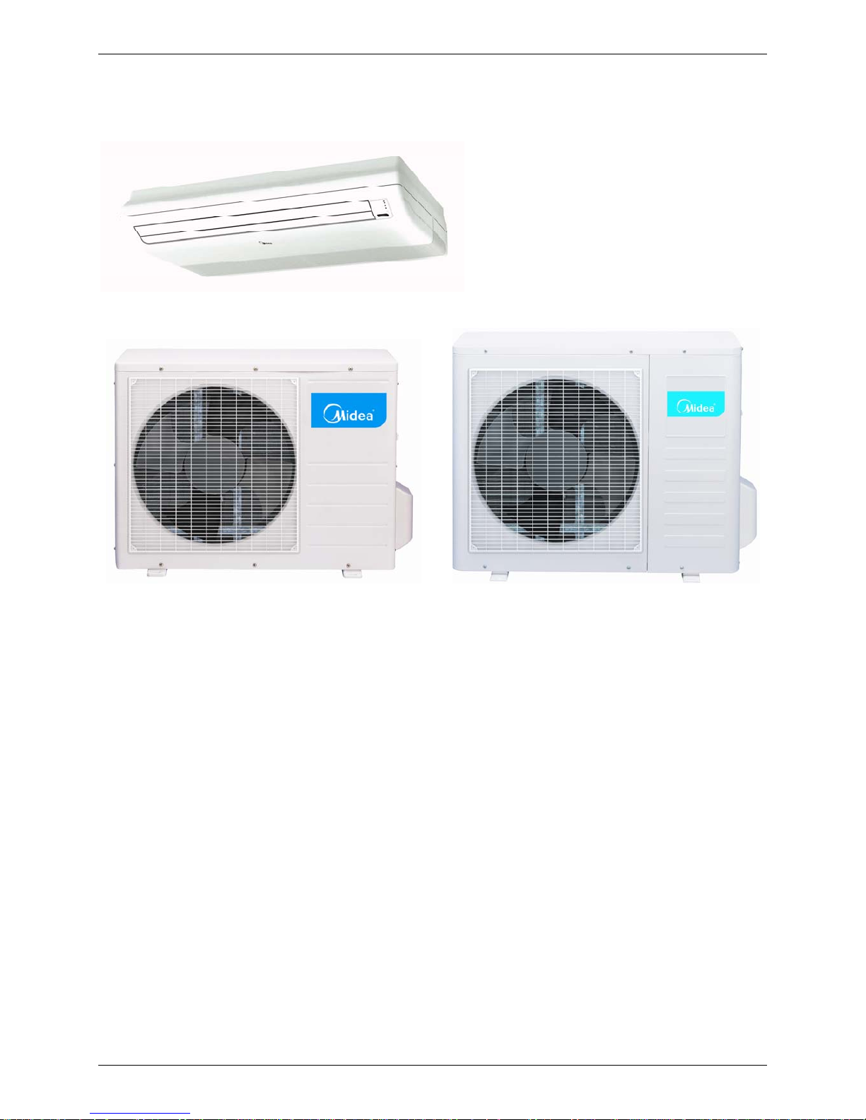
2.1 Indoor units
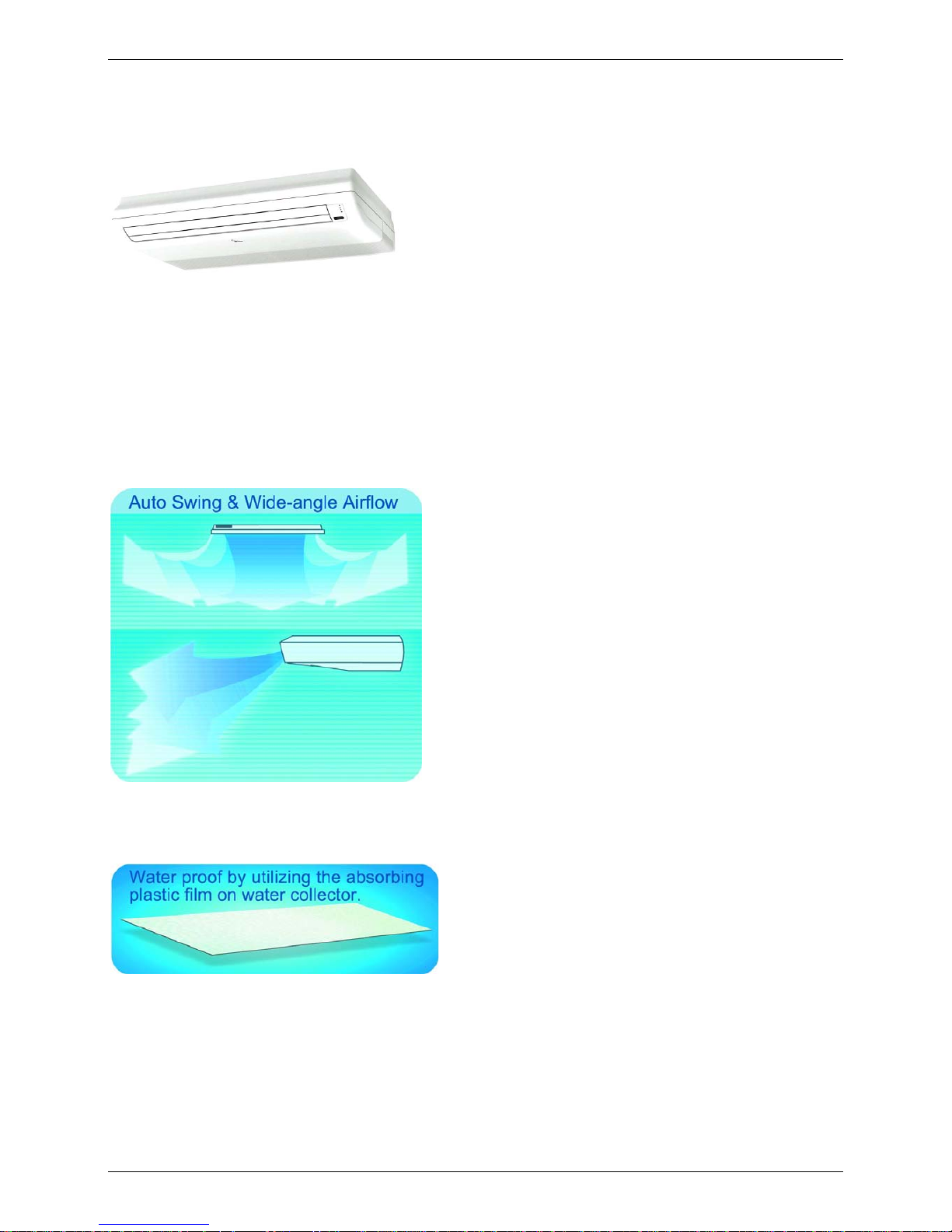
Ceiling and Floor Type:
12000Btu/h and 18000Btu/h
2.2 Outdoor unit
12000Btu/h 18000Btu/h
Page 6
Nomenclature MCAC-UTSM-2008-05
4 General Information
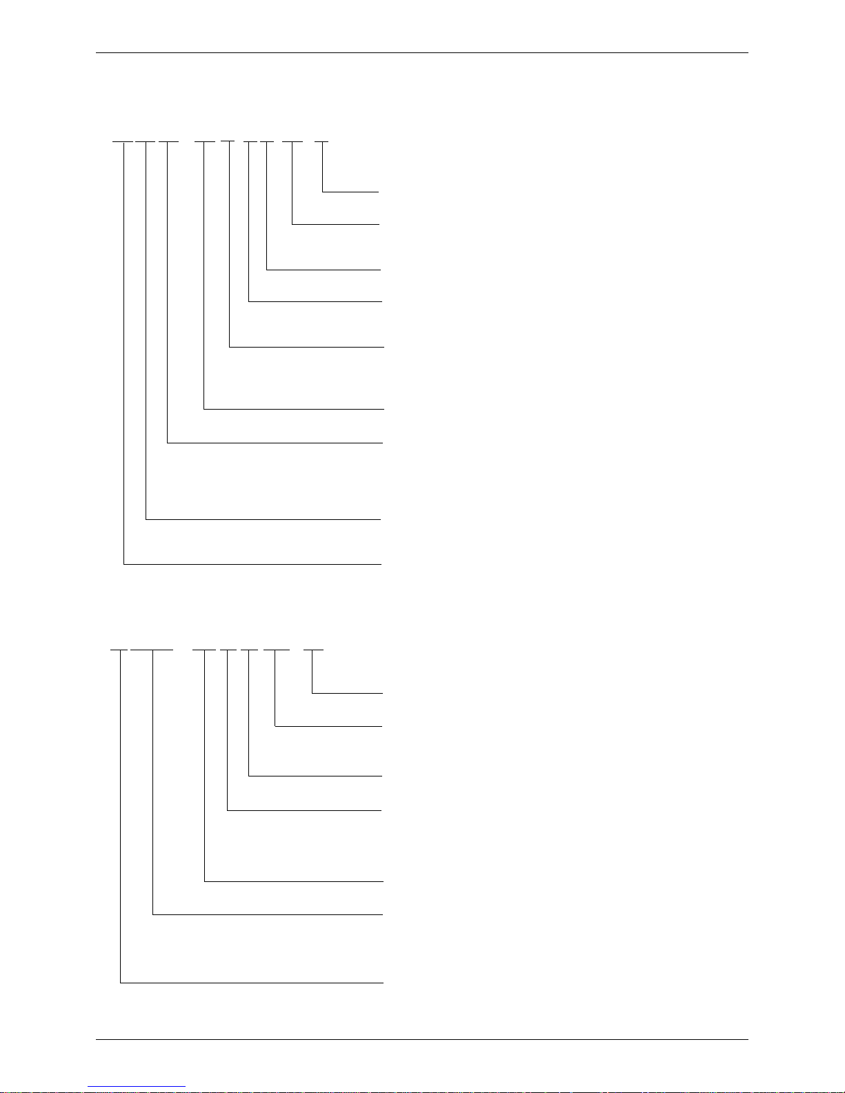
3. Nomenclature
3.1 Indoor Units:
M U B - 12 H R D N1-Q
Q: Quick Connector
Refrigerant Type
N1 : R410A
DC Inverter
Control Mode
R: Remote Control
Function Code
C: Cooling Only
H: Cooling & Heating
Capacity (×1000Btu/h)
Product Series
A: First Time Design
B: Second Time Design
C: Third Time Design
Product Category
U: Ceiling & Floor Type
Midea
3.2 Outdoor Units:
M O U - 12 H D N1- Q
Q: Quick Connector
Refrigerant
N1: R410A
DC Inverter
Function Code
C: Cooling Only
H: Cooling & Heating
Capacity (×1000Btu/h)
Universal Outdoor Unit
O: Outdoor unit
U: Universal
Midea
Page 7
MCAC-UTSM-2008-05 Features
General Information 5
4. Features
4.1 Universal outdoor unit design
Indoor unit with the same capacity can match with the same outdoor unit.
4.2 High efficiency and energy saving.
Thanks to the DC inverter technology and optimized piping system, the EER of whole series can
easily reach A-class.
4.3 Low noise and low starting current.
Thanks to the DC inverter technology, the system can work with low noise, and very small starting
current.
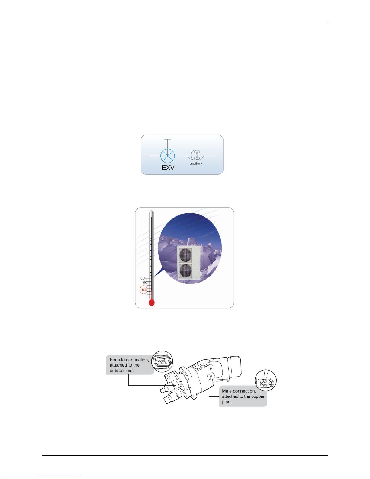
4.4 Intelligent refrigerant adjustment technology(except 12000Btu/h)
Throttle part is made up of capillary and electronic expansion valve (EXV). The outdoor unit can
output the most accurate capacity in any condition.
4.5 Working in cooling mode under -15℃(except 12000Btu/h)
Outdoor unit built-in with low ambient kit, it can control the outdoor unit’s fan and cooling can be
performed throughout the year for computer rooms, banquet halls, etc. Wide operation range
covers outdoor temperatures as low as -15℃ for cooling.
4.6 Convenient installation
--Adopt Quick Connector. The copper pipe connecting the indoor and the outdoor unit is delivered
already connected to the indoor unit. At the other end of the pipe is attached the male part of the
Quick Connector while the female part of the Quick Connector is fixed to the outdoor unit. So it’s easy
to installation.
4.7 Diversiform and universal controller for DC inverter air conditioners, including wireless remote
controller, wired controller (weekly timer, central controller, network controller for 18000Btu/h).
Page 8

Ceiling and Floor Type MCAC-UTSM-2008-05
6 Ceiling and Floor Type
Part 2
Ceiling and Floor Type
1. Features .........................................................................7
2. Specifications................................................................8
3. Dimensions..................................................................12
4. Service Space..............................................................13
5. Wiring Diagrams..........................................................16
6. Air Velocity and Temperature Distributions .............19
7. Capacity Tables...........................................................21
8. Electric Characteristics..............................................24
9. Sound Levels...............................................................25
10. Exploded View...........................................................26
1 1. Accessories ...............................................................32
Page 9
MCAC-UTSM-2008-05 Features
Ceiling and Floor Type 7
1. Features
1.1. New design, more modern and elegant appearance.
1.2. Convenient installation
--The ceiling type can be easily installed into a corner of the ceiling even if the ceiling is very narrow
--It is especially useful when installation of an air conditioner in the center of the ceiling is impossible
due to a structure such as one lighting
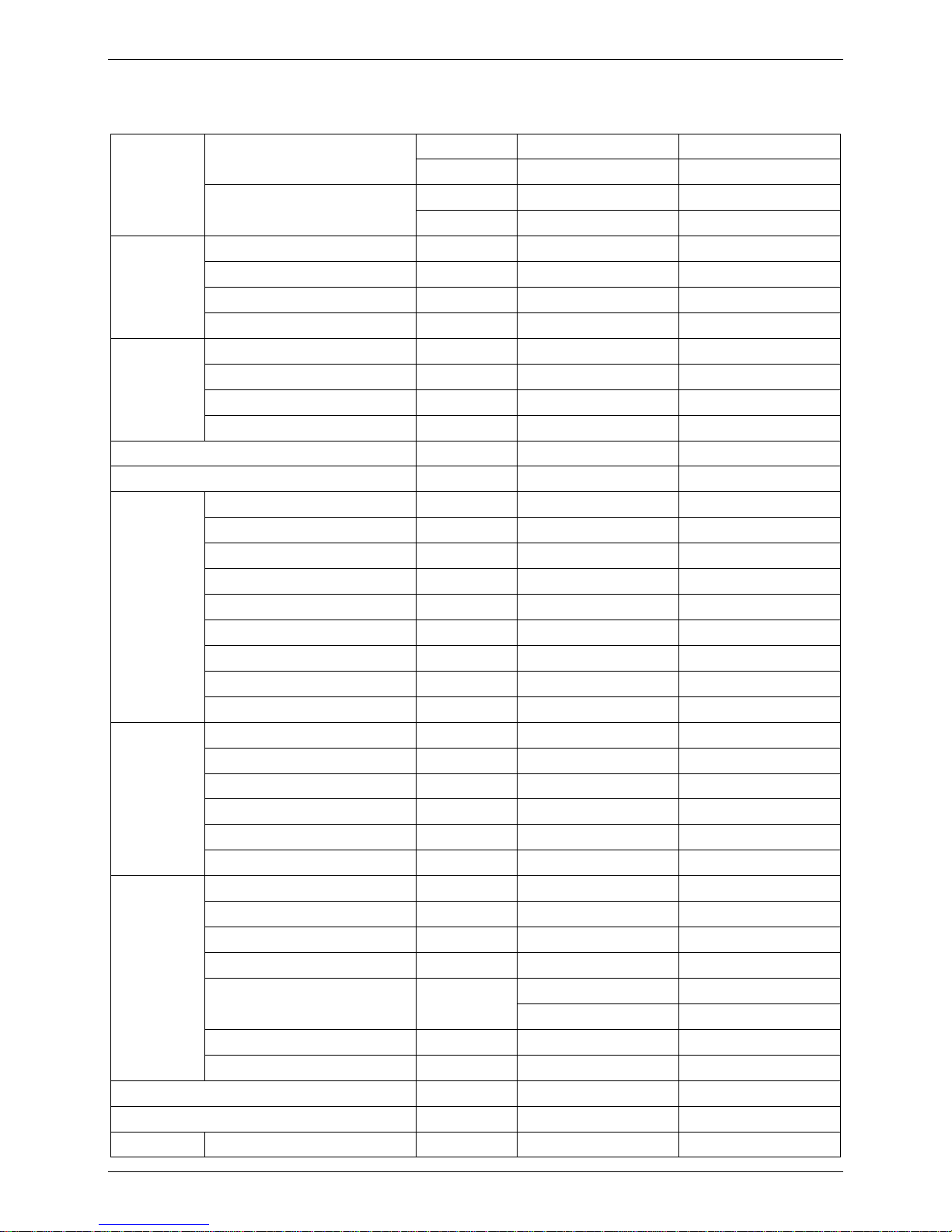
1.3. Two direction auto swing (vertical & horizontal) and wide angle air flow
--Air flow directional control minimizes the air resistance and produces wilder air flow to vertical
direction.
--The range of horizontal air discharge is widened which secures wider air flow distribution to provide
more comfortable air circulation no matter where the unit is set up
1.4. Three level fan speed, more humanism design, meets different air-supply requirement.
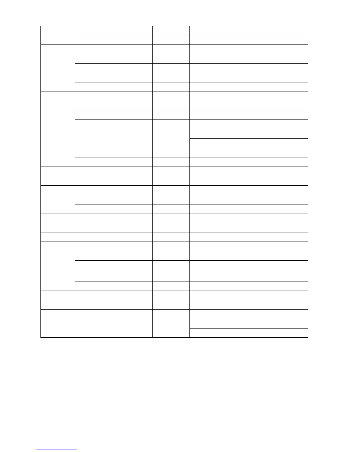
1.5. Water proof by utilizing the absorbing plastic film on water collector
1.6. Easy operation. Auto-restart function, remote control and optional wire control method.
1.7. Low noise level plus compact size
--Shape of the blades has been improved to prevent noise caused by turbulence.
Page 10
Specifications MCAC-UTSM-2008-05
8 Ceiling and Floor Type
2. Specifications
Table 1:
Model name
MUB-12HRDN1-Q MUB-18HRDN1-Q
Indoor Units
Power supply 220-240V-1Ph-50Hz 220-240V-1Ph-50Hz
Model name
MOU-12HRDN1-Q MOU-18HRDN1-Q
Model
Outdoor Units
Power supply 220~240V-1Ph-50Hz 220~240V-1Ph-50Hz
Capacity kW 4.0-3.5-1.4 5.65-5.27-1.7
Input kW 2.55-1.1-0.38 2.6-1.65-0.6
Rated current A 12-5.1-2.0 12.3-7.8-2.5
Cooling
EER 3.2 3.2
Capacity kW 4.75-4.0-1.4 6.2-5.86-1.45
Input kW 2.55-1.13-0.38 2.6-1.73-0.72
Rated current A 12-5.2-2.0 12.3-6.53-3.13
Heating
COP 3.54 3.4
Max. input consumption W 2550 2600
Max. current A 12 12.3
Model DA108X1C-20FZ3 JU1015D4
Type DC Inverter Rotary DC Inverter Rotary
Brand MIDEA TOSHIBA HITACHI
Capacity Btu/h 10921 15012
Input W 855 1585
Rated current(RLA) A 5.3 8.8
Locked rotor Amp(LRA) A 20 30
Thermal protector Internal Internal
Compressor
Refrigerant oil ml ESTER OIL VG74 480ml HAF68D1 580ml
Model YSK25-6L YSK55-4L
Type AC Motor AC Motor
Brand Welling Welling
Input W 33.4/31.1/29.5 125/105/88
Capacitor uF 1.2 2.5
Indoor fan
motor
Speed(hi/mi/lo) r/min 756/666/592 1310/1190/1040
a. Number of rows 3 3
b. Tube pitch(a)x row pitch(b) mm 25.4×22 25.4×22
c. Fin spacing mm 1.8 1.8
d. Fin type (code) Hydrophilic aluminium Hydrophilic aluminium
Ф9.53 Ф9.53
e. Tube outside dia. and type mm
innergroove tube innergroove tube
f. Coil length x height x width mm 804x254x66 804x254x66
Indoor coil
g. Number of circuits 3 3
Indoor air flow (Hi/Mi/Lo) m3/h 584/518/463 1003/907/761
Indoor noise level (Sound pressure)(Hi/Mi/Lo) dB(A) 39.6/36.7/33.1 44.6/41.8/37.3
Indoor unit
Dimension (W×H×D) mm 990x206x660 990x206x660
Page 11
MCAC-UTSM-2008-05 Specifications
Ceiling and Floor Type 9
Packing (W×H×D) mm 1105 x350 x805 1105 x350 x805
Net/Gross weight kg 32/40 34.5/42.5
Model YDK24-6G YDK53-6Y
Brand Welling Welling
Input W 59/43 129/86
Capacitor uF 2.5 3
Outdoor fan
motor
Speed r/min 800/550 770/560
Number of rows 2 2
Tube pitch(a)x row pitch(b) mm 25.4×22 25.4×22
Fin spacing mm 1.4 1.7
Fin type (code) Hydrophilic aluminium Hydrophilic aluminium
Φ9.5 Φ9.5
Tube outside dia. and type mm
Innergroove tube Innergroove tube
Coil length x height x width mm 637×558×44 748×660×44
Outdoor coil
Number of circuits 2 4
Outdoor air flow m3/h 2500/1600 2400/1680
Outdoor noise level(Sound pressure) dB(A) 48/44 52/47
Dimension(W×H×D) mm 761×593×315 842×695×360
Packing (W×H×D) mm 887×655×355 970×770×400
Outdoor unit
Net/Gross weight kg 42/45 62/66
Refrigerant type g R410A/1400 R410A/1700
Throttle type Capillary Capillary +EXV
Design pressure MPa 2.0/4.2 2.0/4.2
Liquid side/ Gas side mm Ф6.4/Ф12.7 Ф6.4/Ф12.7
Max. refrigerant pipe length m 5 5
Refrigerant
piping
Max. difference between outdoor
unit and indoor unit
m 5 5
Power wiring mm2 3×1.5 3×2.5
Connection
wiring
Signal wiring mm2 4×1.5 4×0.5
Drainage pipe diameter mm2 Ф16 Ф16
Controller R05/BGE (standard) R05/BGE (standard)
Operation temp
℃
17-30 17-30
Coolimg:21℃-43℃; Coolimg:-15℃-43℃;
Ambient temp ℃
Heating:-5℃-24℃ Heating:-5℃-24℃
Page 12
Specifications MCAC-UTSM-2008-05
10 Ceiling and Floor Type
Table 2:
Model name
MUB-12HRDN1
Indoor Units
Power supply 220-240V-1Ph-50Hz
Model name
MOU-12HRDN1
Model
Outdoor Units
Power supply 220~240V-1P-50Hz
Capacity kW 4.0-3.5-1.4
Input kW 2.55-1.08-0.38
Rated current A 12-5.1-2.0
Cooling
EER 3.24
Capacity kW 4.75-4.0-1.4
Input kW 2.55-1.12-0.38
Rated current A 12-5.2-2.0
Heating
COP 3.6
Max. input consumption W 2550
Max. current A 12
Model DA108X1C-20FZ3
Type DC Inverter Rotary
Brand MIDEA TOSHIBA
Capacity Btu/h 10921
Input W 855
Rated current(RLA) A 5.3
Locked rotor Amp(LRA) A 20
Thermal protector Internal
Compressor
Refrigerant oil ml ESTER OIL VG74 480ml
Model YSK25-6L
Type AC Motor
Brand Welling
Input W 33.4/31.1/29.5
Capacitor uF 1.2
Indoor fan motor
Speed(hi/mi/lo) r/min 756/666/592
a. Number of rows 3
b. Tube pitch(a)x row pitch(b) mm 25.4×22
c. Fin spacing mm 1.8
d. Fin type (code) Hydrophilic aluminium
Ф9.53
e. Tube outside dia. and type mm
innergroove tube
f. Coil length x height x width mm 804x254x66
Indoor coil
g. Number of circuits 3
Indoor air flow (Hi/Mi/Lo) m3/h 584/518/463
Indoor noise level (Sound pressure)(Hi/Mi/Lo) dB(A) 39.6/36.7/33.1
Dimension (W×H×D) mm 990x206x660
Indoor unit
Packing (W×H×D) mm 1089x296 x744
Page 13
MCAC-UTSM-2008-05 Specifications
Ceiling and Floor Type 11
Net/Gross weight kg 27/33
Model YDK24-6G
Brand Welling
Input W 59/43
Capacitor uF 2.5
Outdoor fan motor
Speed r/min 800/550
Number of rows 2
Tube pitch(a)x row pitch(b) mm 25.4×22
Fin spacing mm 1.4
Fin type (code) Hydrophilic aluminium
Φ9.5
Tube outside dia. and type mm
Innergroove tube
Coil length x height x width mm 637×558×44
Outdoor coil
Number of circuits 2
Outdoor air flow m3/h 2500/1600
Outdoor noise level(Sound pressure) dB(A) 48/44
Dimension(W×H×D) mm 761×593×315
Packing (W×H×D) mm 887×655×355
Outdoor unit
Net/Gross weight kg 39.5/42.5
Refrigerant type g R410A/1400
Throttle type Capillary
Design pressure MPa 2.0/4.2
Liquid side/ Gas side mm Ф6.4/Ф12.7
Max. refrigerant pipe length m 10
Refrigerant piping
Max. difference between outdoor unit and
indoor unit
m 5
Power wiring mm2 3×1.5
Connection wiring
Signal wiring mm2 4×1.5
Drainage pipe diameter mm2 Ф16
Controller R05/BGE (standard)
Operation temp
℃
17-30
Coolimg:21℃-43℃;
Ambient temp ℃
Heating:-5℃-24℃
Page 14
Dimensions MCAC-UTSM-2008-05
12 Ceiling and Floor Type
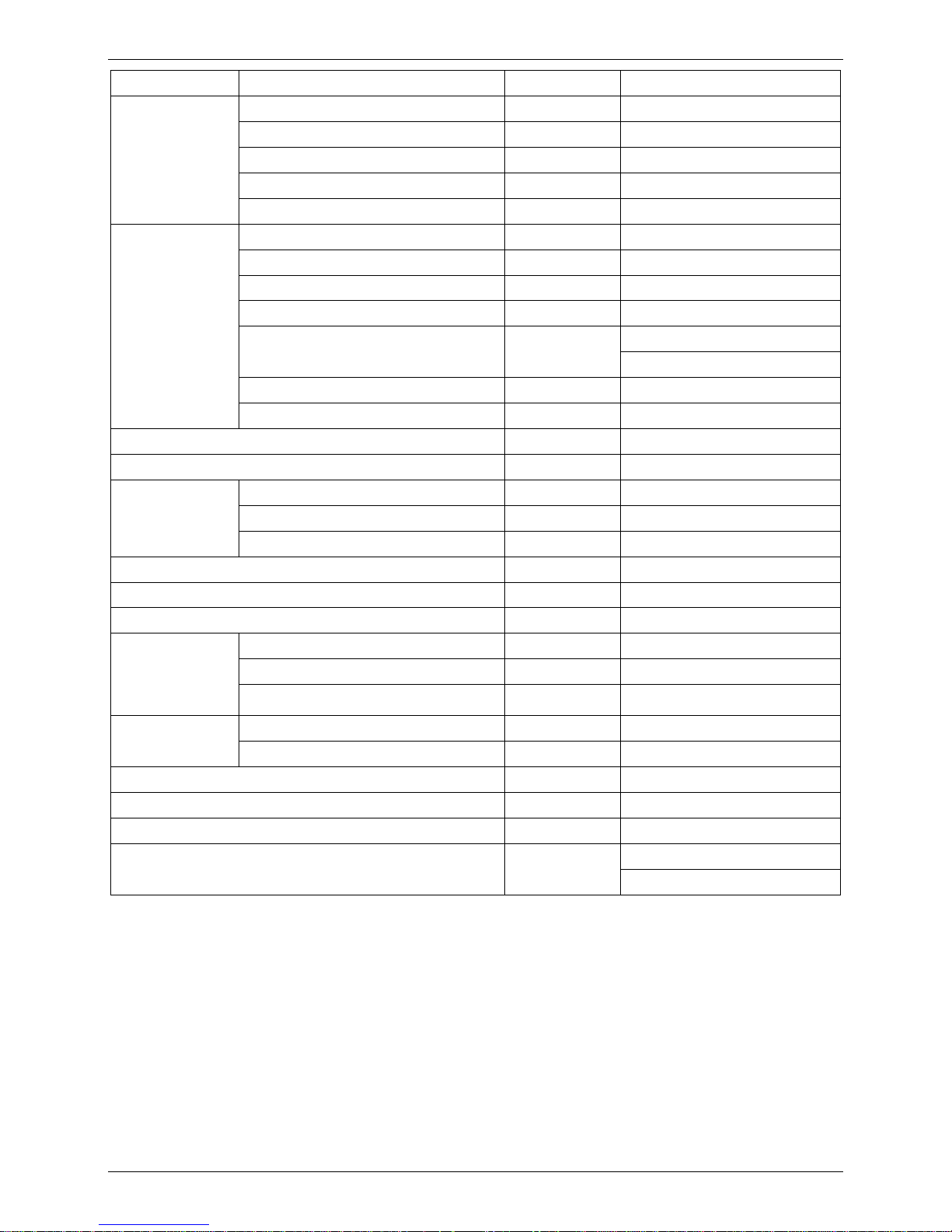
3. Dimensions
3.1 12HRDN1-Q MUB-18HRDN1-Q
3.2 MUB-12HRDN1-Q
Capacity A B C
12000Btu/h 990 606 206
Page 15
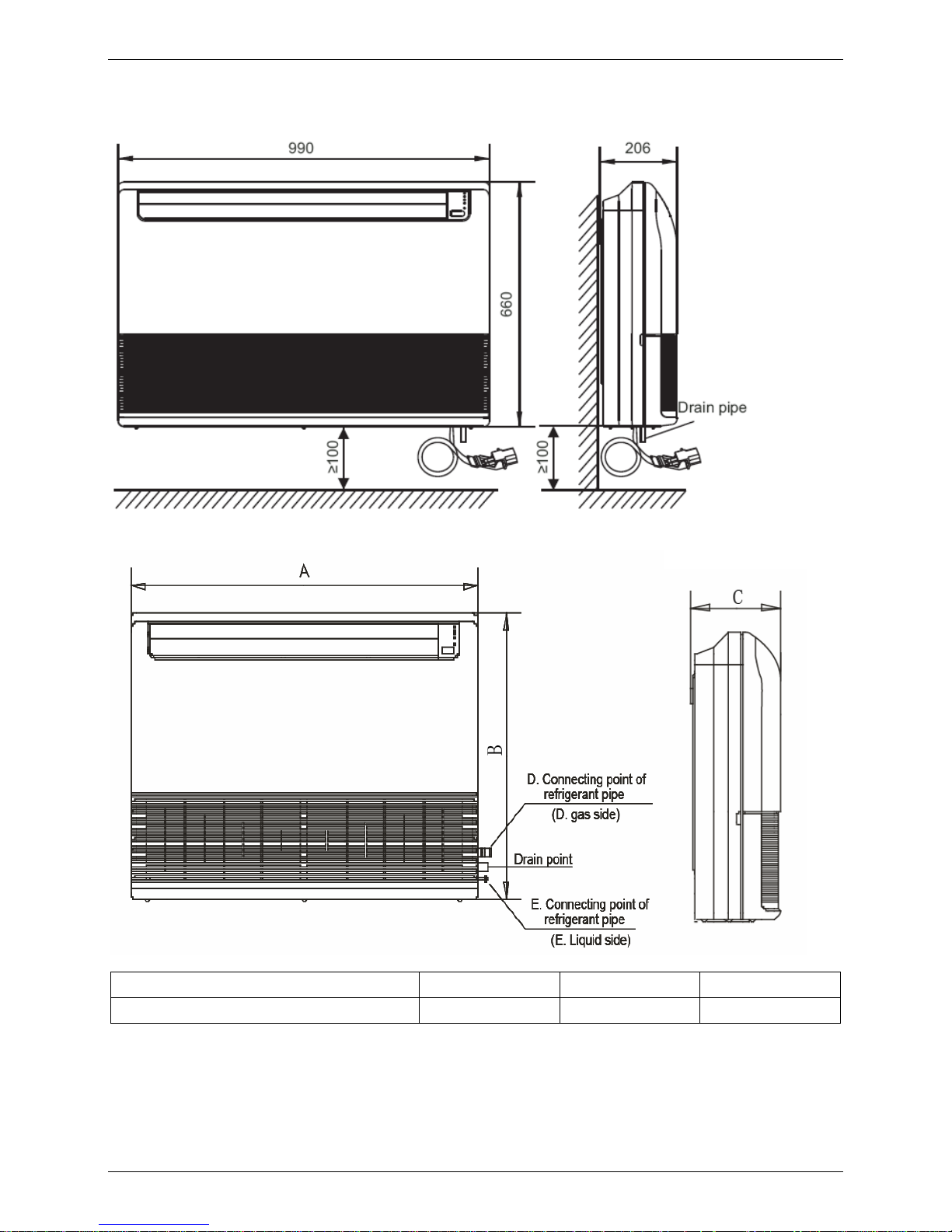
MCAC-UTSM-2008-05 Service Space
Ceiling and Floor Type 13
4. Service Space
4.1 MUB-12HRDN1-Q MUB-18HRDN1-Q
Wall Mounting Installation:
Page 16
Service Space MCAC-UTSM-2008-05
14 Ceiling and Floor Type
Ceiling Installation:
4.2 MUB-12HRDN1
Wall Mounting Installation:
Page 17
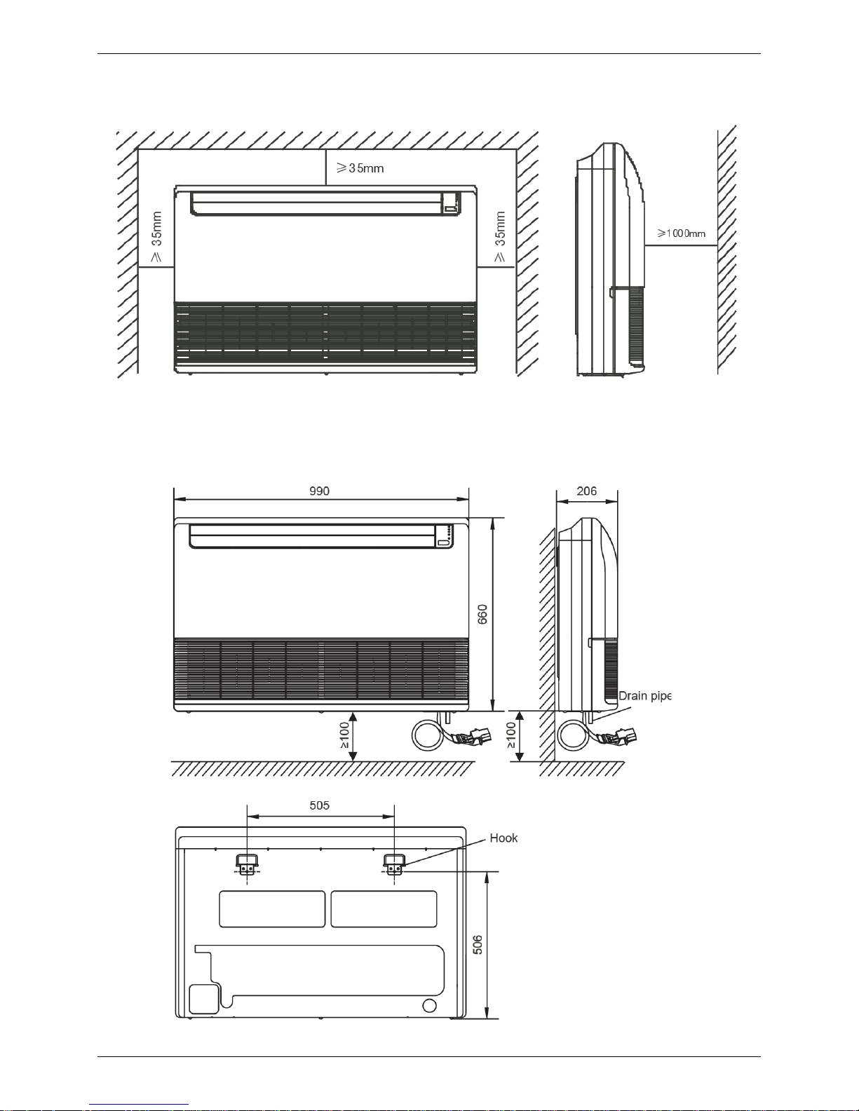
MCAC-UTSM-2008-05 Service Space
Ceiling and Floor Type 15
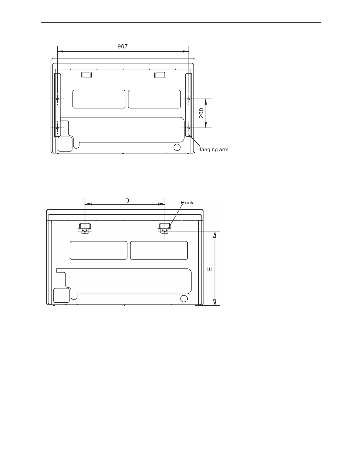
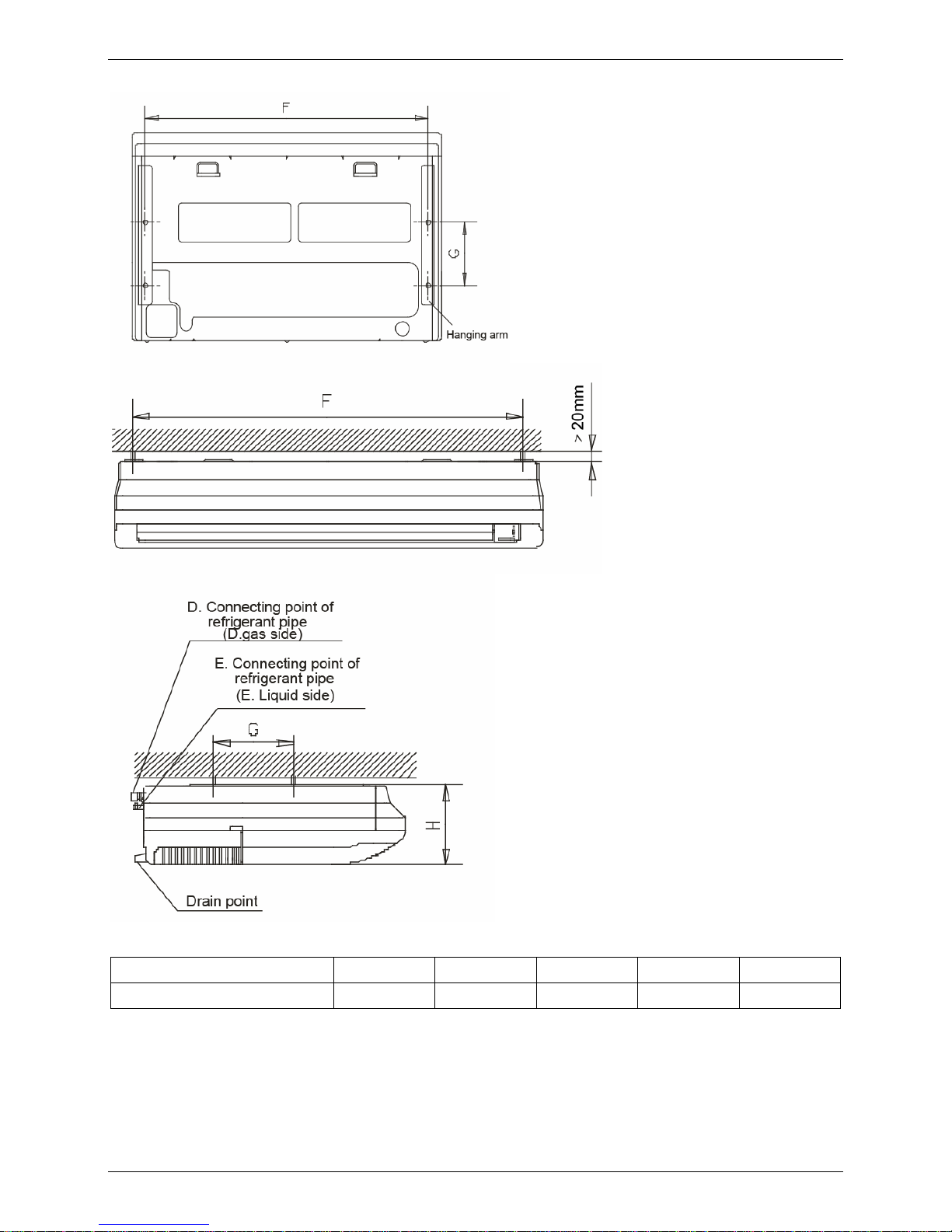
Ceiling Installation:
Capacity D E F G H
12000Btu/h 505 506 907 200 203
Page 18
Wiring Diagrams MCAC-UTSM-2008-05
16 Ceiling and Floor Type
5. Wiring Diagrams
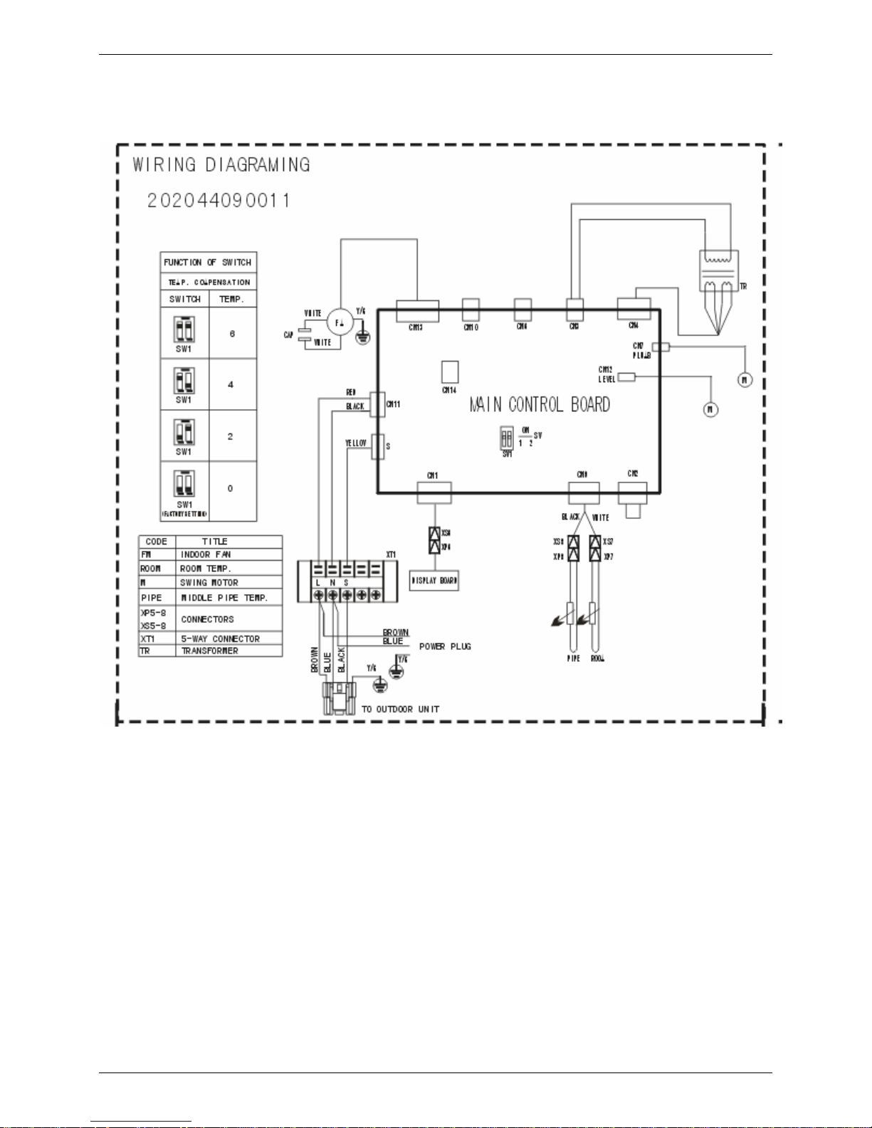
5.1 MUB-12HRDN1-Q
Page 19
MCAC-UTSM-2008-05 Wiring Diagrams
Ceiling and Floor Type 17
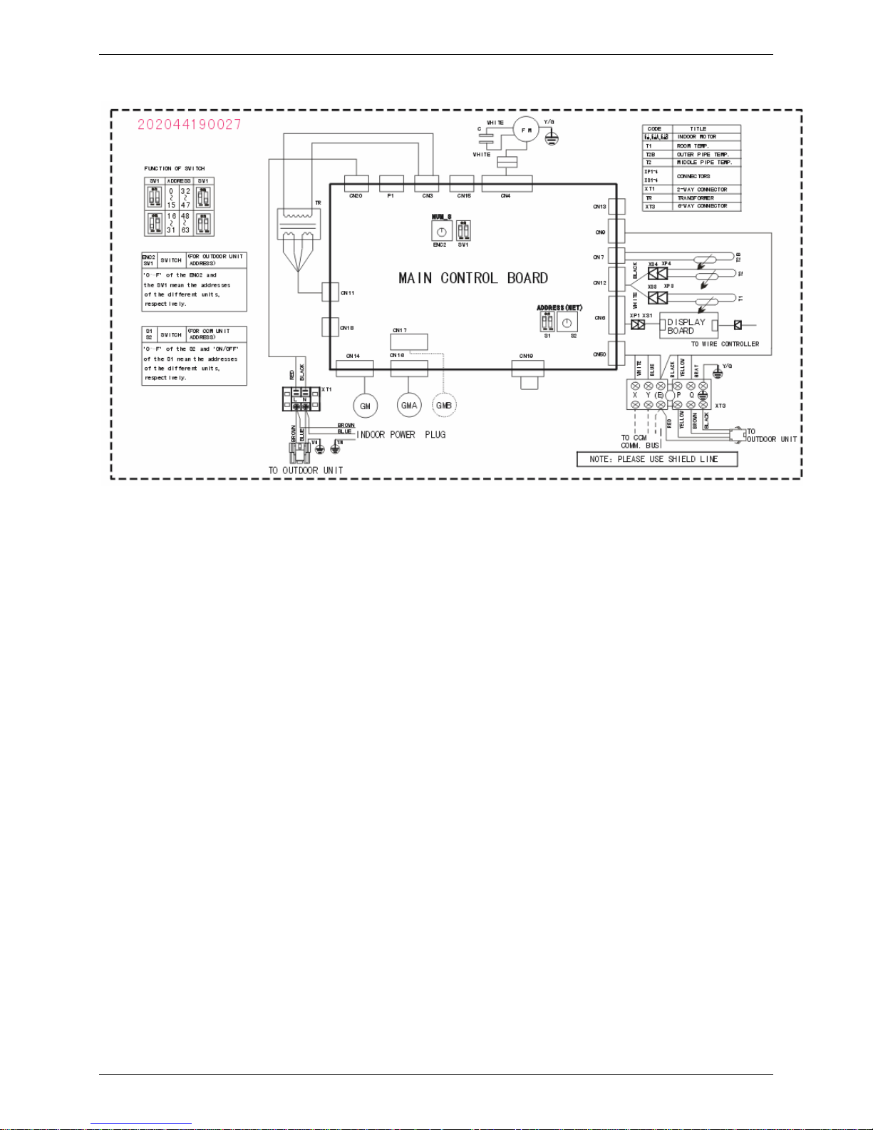
5.2 MUB-18HRDN1-Q
Page 20
Wiring Diagrams MCAC-UTSM-2008-05
18 Ceiling and Floor Type
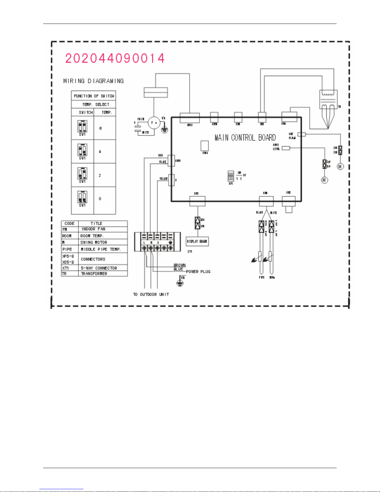
5.3 MUB-12HRDN1
Page 21
MCAC-UTSM-2008-05 Air Velocity and Temperature Distributions
Ceiling and Floor Type 19
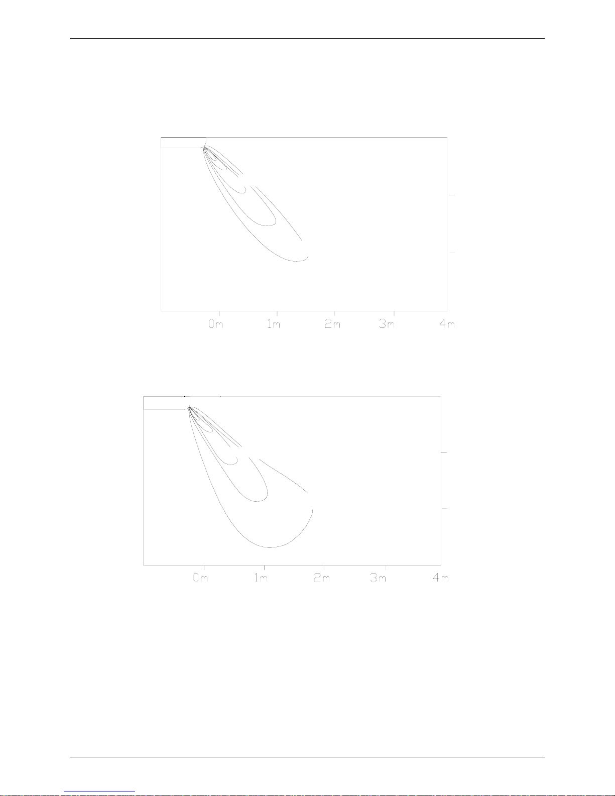
6. Air Velocity and Temperature Distributions
Discharge angle 60°(Ceiling)
Airflow velocity
1.5m/sec
0.5m/sec
3m
2m
1m
0m
Temperature
27° C
22° C
3m
2m
1m
0m
Page 22
Air Velocity and Temperature Distributions MCAC-UTSM-2008-05
20 Ceiling and Floor Type
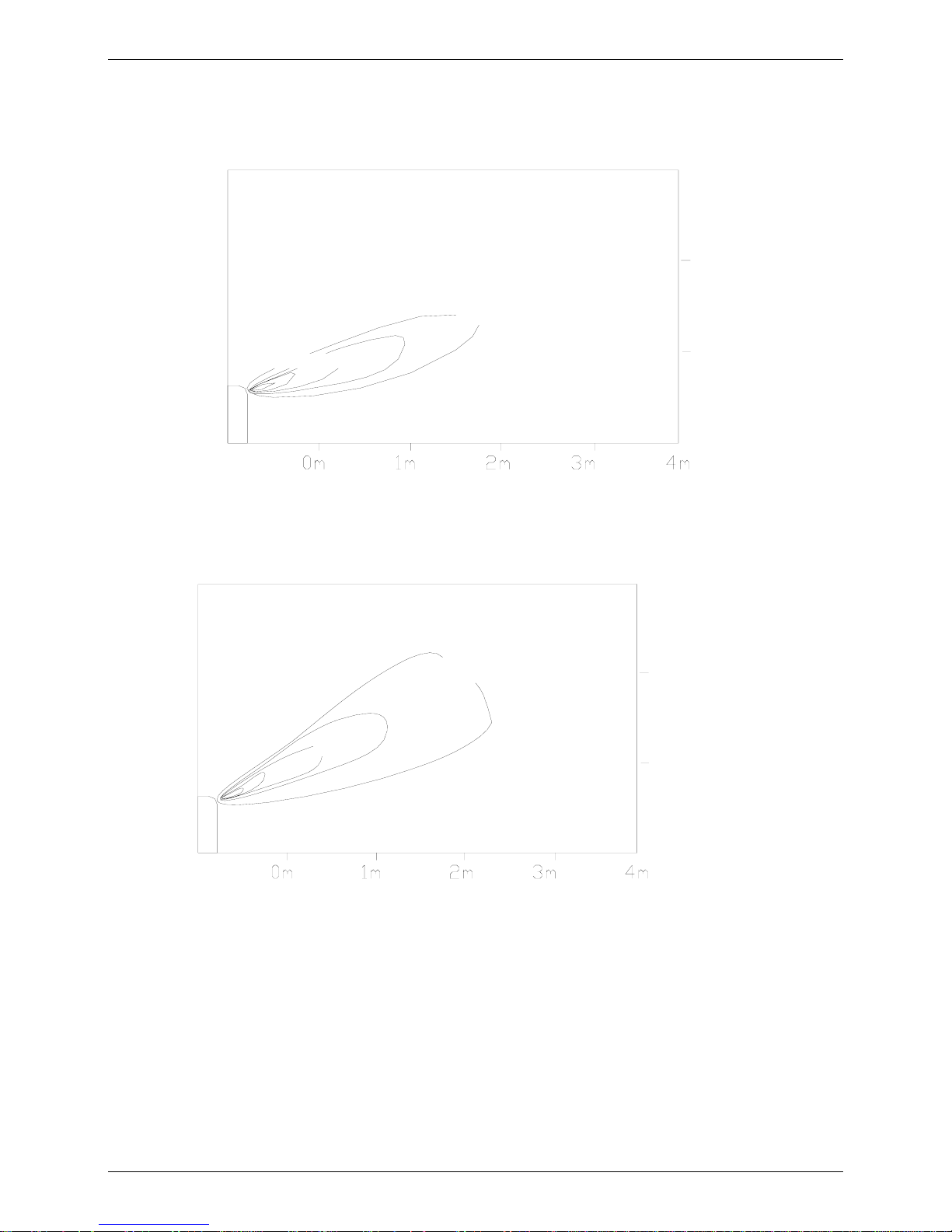
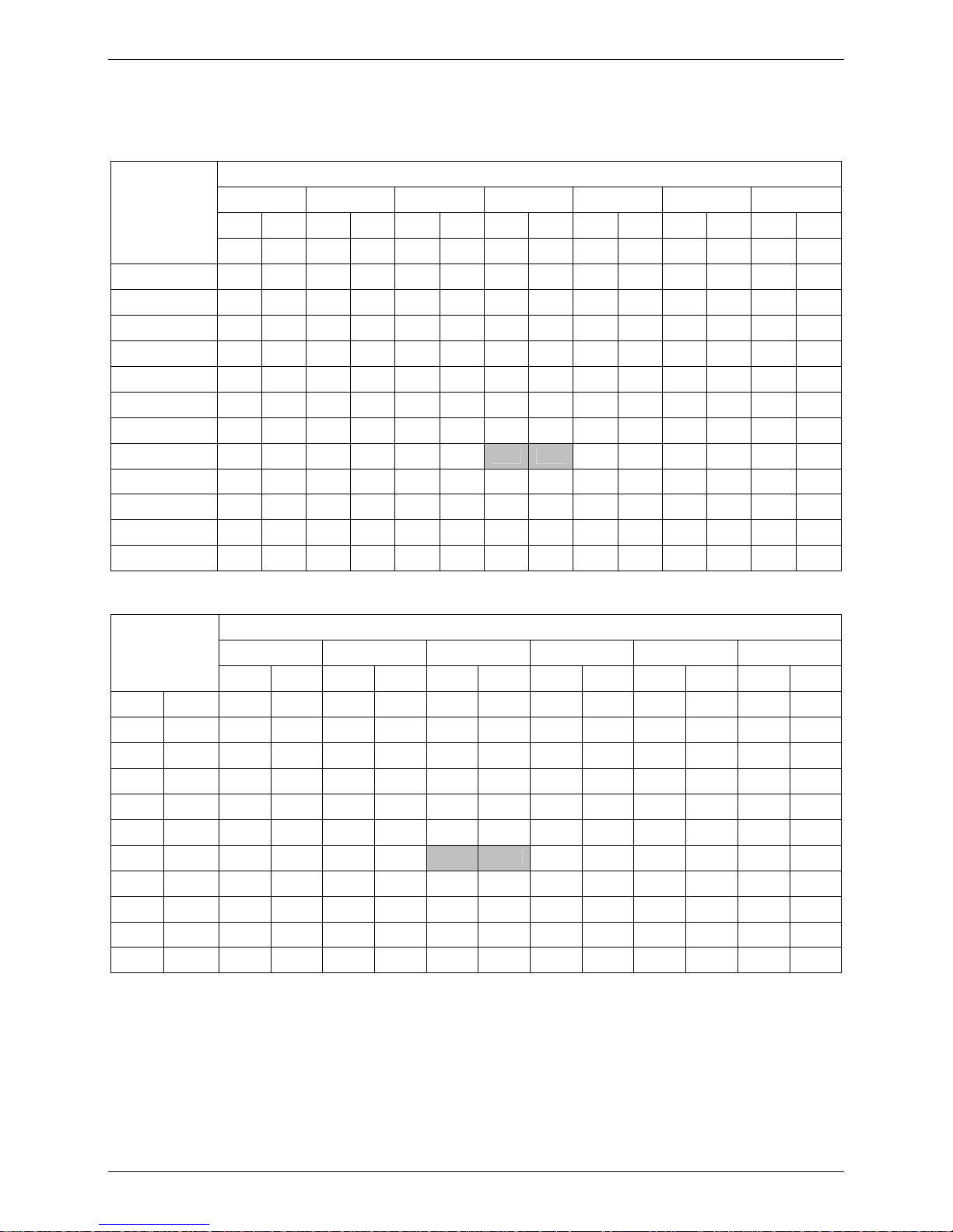
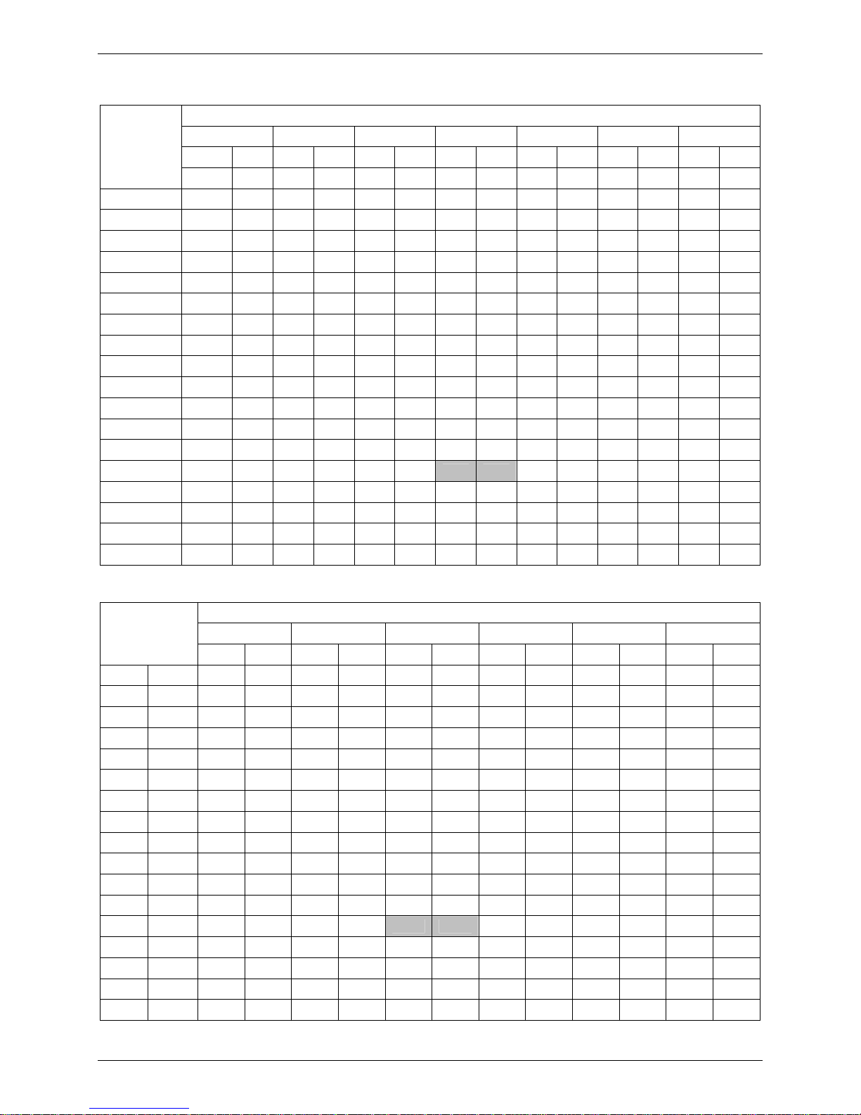
Discharge angle 60°(Floor)
Airflow velocity
0.5m/sec
1.5m/sec
3m
2m
1m
0m
Temperature
3m
2m
1m
0m
22° C
27° C
Page 23
MCAC-UTSM-2008-05 Capacity Tables
Ceiling and Floor Type 21
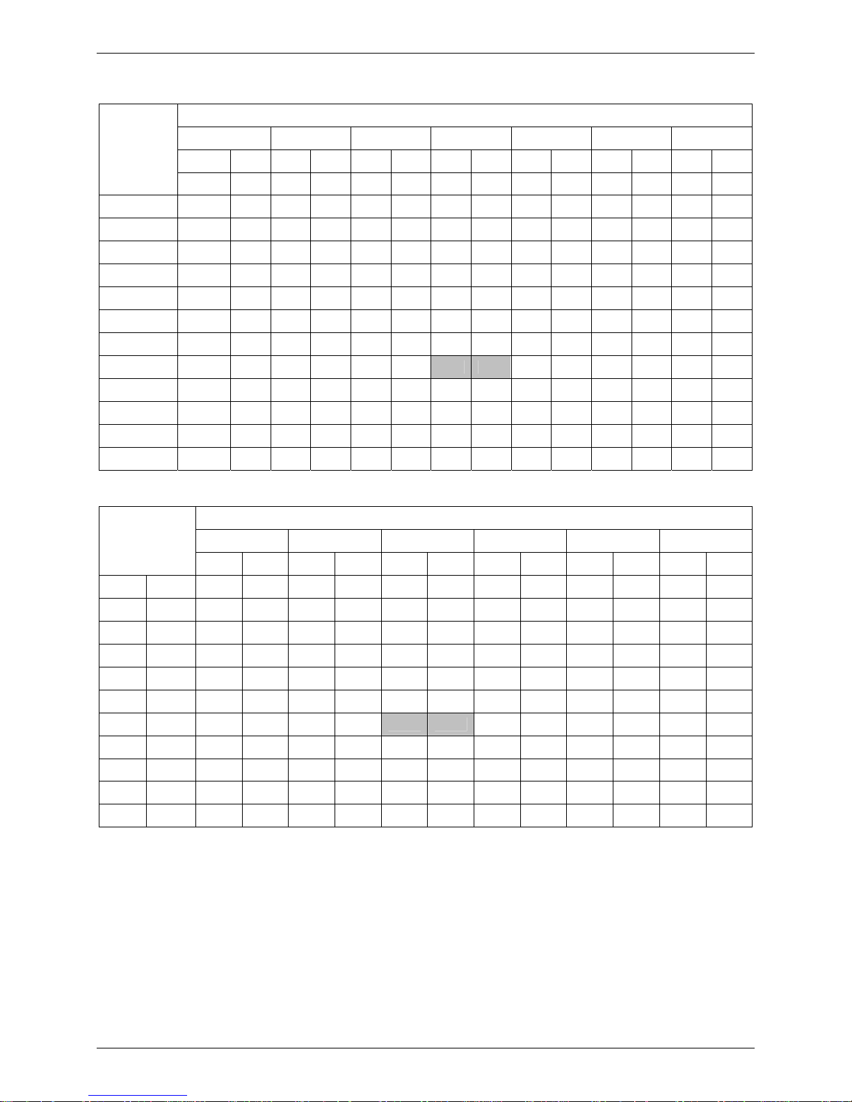
7. Capacity Tables
7.1 MUB-12HRDN1-Q:
Cooling:
Indoor temperature(°CWB)
14.00 16.00 18.00 19.00 20.00 22.00 24.00
TC PI TC PI TC PI TC PI TC PI TC PI TC PI
Outdoor
temperature(°C
DB)
kW kW kW kW kW kW kW kW kW kW kW kW kW kW
21.00 2.42 0.43 2.86 0.54 3.30 0.64 3.50 0.70 3.70 0.75 3.78 0.75 3.86 0.76
23.00 2.42 0.46 2.86 0.57 3.30 0.69 3.50 0.75 3.70 0.80 3.78 0.81 3.86 0.81
25.00 2.42 0.49 2.86 0.61 3.30 0.74 3.50 0.80 3.70 0.86 3.78 0.86 3.86 0.87
27.00 2.42 0.53 2.86 0.66 3.30 0.79 3.50 0.85 3.70 0.92 3.78 0.92 3.86 0.93
29.00 2.42 0.56 2.86 0.70 3.30 0.84 3.50 0.91 3.70 0.98 3.78 0.98 3.86 0.99
31.00 2.42 0.60 2.86 0.75 3.30 0.90 3.50 0.97 3.70 1.05 3.78 1.05 3.86 1.06
33.00 2.42 0.64 2.86 0.80 3.30 0.95 3.50 1.03 3.70 1.11 3.78 1.12 3.86 1.13
35.00 2.42 0.68 2.86 0.85 3.30 1.01 3.50 1.10 3.70 1.19 3.78 1.19 3.86 1.20
37.00 2.42 0.72 2.86 0.90 3.30 1.08 3.50 1.17 3.70 1.26 3.78 1.27 3.86 1.28
39.00 2.42 0.73 2.86 0.90 3.30 1.08 3.50 1.18 3.70 1.27 3.78 1.27 3.86 1.28
41.00 2.42 0.73 2.86 0.91 3.30 1.09 3.50 1.18 3.70 1.27 3.78 1.28 3.86 1.29
43.00 2.42 0.73 2.86 0.91 3.30 1.09 3.50 1.19 3.70 1.28 3.78 1.28 3.86 1.29
Heating:
Indoor temperature(°C DB)
16 18 20 21 22 24
Outdoor air
temp.
TC PI TC PI TC PI TC PI TC PI TC PI
°C DB °C WB kW kW kW kW kW kW kW kW kW kW kW kW
-5 -5.6 3.19 1.00 3.19 1.02 3.19 1.04 3.07 0.99 2.94 0.95 2.69 0.86
-3 -3.7 3.33 1.01 3.33 1.03 3.33 1.05 3.20 1.01 3.06 0.96 2.80 0.87
0 -0.7 3.53 1.03 3.53 1.05 3.53 1.08 3.39 1.03 3.25 0.98 2.97 0.89
3 2.2 3.73 1.05 3.73 1.08 3.73 1.10 3.58 1.05 3.43 1.00 3.14 0.91
5 4.1 3.87 1.07 3.87 1.09 3.87 1.11 3.71 1.07 3.56 1.02 3.25 0.92
7 6 4.00 1.08 4.00 1.11 4.00 1.13 3.84 1.08 3.68 1.03 3.37 0.93
9 7.9 4.00 1.05 4.00 1.07 4.00 1.09 3.84 1.04 3.68 1.00 3.37 0.90
11 9.8 4.00 1.01 4.00 1.03 4.00 1.05 3.84 1.01 3.68 0.96 3.37 0.87
13 11.8 4.00 0.97 4.00 1.00 4.00 1.02 3.84 0.97 3.68 0.93 3.37 0.84
15 13.7 4.00 0.94 4.00 0.96 4.00 0.98 3.84 0.94 3.68 0.89 3.37 0.81
Page 24
Capacity Tables MCAC-UTSM-2008-05
22 Ceiling and Floor Type
7.2 MUB-18HRDN1-Q:
Cooling:
Indoor temperature(°CWB)
14.00 16.00 18.00 19.00 20.00 22.00 24.00
TC PI TC PI TC PI TC PI TC PI TC PI TC PI
Outdoor
temperature
(°C DB)
kW kW kW kW kW kW kW kW kW kW kW kW kW kW
10.00 3.65 0.55 4.31 0.69 4.97 0.82 5.27 0.89 5.57 0.96 5.69 0.96 5.82 0.97
12.00 3.65 0.56 4.31 0.70 4.97 0.84 5.27 0.91 5.57 0.98 5.69 0.98 5.82 0.99
14.00 3.65 0.57 4.31 0.71 4.97 0.85 5.27 0.92 5.57 1.00 5.69 1.00 5.82 1.01
16.00 3.65 0.58 4.31 0.72 4.97 0.87 5.27 0.94 5.57 1.01 5.69 1.02 5.82 1.03
18.00 3.65 0.59 4.31 0.74 4.97 0.88 5.27 0.96 5.57 1.03 5.69 1.03 5.82 1.04
19.00 3.65 0.60 4.31 0.75 4.97 0.90 5.27 0.97 5.57 1.05 5.69 1.05 5.82 1.06
21.00 3.65 0.64 4.31 0.80 4.97 0.96 5.27 1.04 5.57 1.13 5.69 1.13 5.82 1.14
23.00 3.65 0.69 4.31 0.86 4.97 1.03 5.27 1.12 5.57 1.21 5.69 1.21 5.82 1.22
25.00 3.65 0.74 4.31 0.92 4.97 1.10 5.27 1.20 5.57 1.29 5.69 1.29 5.82 1.31
27.00 3.65 0.79 4.31 0.98 4.97 1.18 5.27 1.28 5.57 1.38 5.69 1.38 5.82 1.40
29.00 3.65 0.84 4.31 1.05 4.97 1.26 5.27 1.37 5.57 1.47 5.69 1.48 5.82 1.49
31.00 3.65 0.90 4.31 1.12 4.97 1.34 5.27 1.46 5.57 1.57 5.69 1.57 5.82 1.59
33.00 3.65 0.96 4.31 1.19 4.97 1.43 5.27 1.55 5.57 1.67 5.69 1.68 5.82 1.69
35.00 3.65 1.02 4.31 1.27 4.97 1.52 5.27 1.65 5.57 1.78 5.69 1.78 5.82 1.80
37.00 3.65 1.08 4.31 1.35 4.97 1.62 5.27 1.75 5.57 1.89 5.69 1.90 5.82 1.92
39.00 3.65 1.09 4.31 1.36 4.97 1.63 5.27 1.76 5.57 1.90 5.69 1.91 5.82 1.92
41.00 3.65 1.09 4.31 1.36 4.97 1.63 5.27 1.77 5.57 1.91 5.69 1.91 5.82 1.93
43.00 3.65 1.10 4.31 1.37 4.97 1.64 5.27 1.78 5.57 1.92 5.69 1.92 5.82 1.94
Heating:
Indoor temperature(°C DB)
16 18 20 21 22 24
Outdoor air
temp.
TC PI TC PI TC PI TC PI TC PI TC PI
°C DB °C WB kW kW kW kW kW kW kW kW kW kW kW kW
-14.7 -15 3.72 1.42 3.72 1.45 3.72 1.48 3.57 1.41 3.43 1.35 3.13 1.22
-12.6 -13 3.93 1.44 3.93 1.47 3.93 1.50 3.77 1.44 3.62 1.37 3.30 1.24
-10.5 -11 4.13 1.46 4.13 1.50 4.13 1.53 3.97 1.46 3.81 1.39 3.48 1.26
-9.5 -10 4.23 1.48 4.23 1.51 4.23 1.54 4.07 1.47 3.90 1.40 3.56 1.27
-8.5 -9.1 4.33 1.49 4.33 1.52 4.33 1.55 4.16 1.48 3.99 1.41 3.64 1.28
-7 -7.6 4.48 1.50 4.48 1.54 4.48 1.57 4.30 1.50 4.12 1.43 3.77 1.29
-5 -5.6 4.68 1.53 4.68 1.56 4.68 1.59 4.49 1.52 4.31 1.45 3.93 1.31
-3 -3.7 4.87 1.55 4.87 1.58 4.87 1.61 4.68 1.54 4.49 1.47 4.10 1.33
0 -0.7 5.17 1.58 5.17 1.61 5.17 1.65 4.96 1.58 4.76 1.50 4.35 1.36
3 2.2 5.47 1.61 5.47 1.65 5.47 1.68 5.25 1.61 5.03 1.54 4.60 1.39
5 4.1 5.66 1.64 5.66 1.67 5.66 1.71 5.44 1.63 5.21 1.56 4.76 1.41
7 6 5.86 1.66 5.86 1.69 5.86 1.73 5.63 1.65 5.39 1.58 4.93 1.43
9 7.9 5.86 1.60 5.86 1.64 5.86 1.67 5.63 1.60 5.39 1.53 4.93 1.38
11 9.8 5.86 1.55 5.86 1.58 5.86 1.61 5.63 1.54 5.39 1.47 4.93 1.33
13 11.8 5.86 1.49 5.86 1.52 5.86 1.56 5.63 1.49 5.39 1.42 4.93 1.28
15 13.7 5.86 1.44 5.86 1.47 5.86 1.50 5.63 1.43 5.39 1.37 4.93 1.24
Page 25
MCAC-UTSM-2008-05 Capacity Tables
Ceiling and Floor Type 23
7.3 MUB-12HRDN1:
Cooling:
Indoor temperature(°CWB)
14.00 16.00 18.00 19.00 20.00 22.00 24.00
TC PI TC PI TC PI TC PI TC PI TC PI TC PI
Outdoor
temperature
(°C DB)
kW kW kW kW kW kW kW kW kW kW kW kW kW kW
21.00 2.42 0.42 2.86 0.53 3.30 0.63 3.50 0.68 3.70 0.74 3.78 0.74 3.86 0.75
23.00 2.42 0.45 2.86 0.56 3.30 0.67 3.50 0.73 3.70 0.79 3.78 0.79 3.86 0.80
25.00 2.42 0.48 2.86 0.60 3.30 0.72 3.50 0.78 3.70 0.84 3.78 0.85 3.86 0.85
27.00 2.42 0.52 2.86 0.64 3.30 0.77 3.50 0.84 3.70 0.90 3.78 0.91 3.86 0.91
29.00 2.42 0.55 2.86 0.69 3.30 0.82 3.50 0.89 3.70 0.96 3.78 0.97 3.86 0.98
31.00 2.42 0.59 2.86 0.73 3.30 0.88 3.50 0.95 3.70 1.03 3.78 1.03 3.86 1.04
33.00 2.42 0.63 2.86 0.78 3.30 0.94 3.50 1.02 3.70 1.09 3.78 1.10 3.86 1.11
35.00 2.42 0.67 2.86 0.83 3.30 1.00 3.50 1.08 3.70 1.16 3.78 1.17 3.86 1.18
37.00 2.42 0.71 2.86 0.88 3.30 1.06 3.50 1.15 3.70 1.24 3.78 1.24 3.86 1.25
39.00 2.42 0.71 2.86 0.89 3.30 1.06 3.50 1.15 3.70 1.24 3.78 1.25 3.86 1.26
41.00 2.42 0.72 2.86 0.89 3.30 1.07 3.50 1.16 3.70 1.25 3.78 1.25 3.86 1.27
43.00 2.42 0.72 2.86 0.90 3.30 1.07 3.50 1.16 3.70 1.26 3.78 1.26 3.86 1.27
Heating:
Indoor temperature(°C DB)
16 18 20 21 22 24
Outdoor air
temp.
TC PI TC PI TC PI TC PI TC PI TC PI
°C DB °C WB kW kW kW kW kW kW kW kW kW kW kW kW
-5 -5.6 3.19 0.99 3.19 1.01 3.19 1.03 3.07 0.98 2.94 0.94 2.69 0.85
-3 -3.7 3.33 1.00 3.33 1.02 3.33 1.04 3.20 1.00 3.06 0.95 2.80 0.86
0 -0.7 3.53 1.02 3.53 1.05 3.53 1.07 3.39 1.02 3.25 0.97 2.97 0.88
3 2.2 3.73 1.05 3.73 1.07 3.73 1.09 3.58 1.04 3.43 0.99 3.14 0.90
5 4.1 3.87 1.06 3.87 1.08 3.87 1.10 3.71 1.06 3.56 1.01 3.25 0.91
7 6 4.00 1.07 4.00 1.10 4.00 1.12 3.84 1.07 3.68 1.02 3.37 0.92
9 7.9 4.00 1.04 4.00 1.06 4.00 1.08 3.84 1.03 3.68 0.99 3.37 0.89
11 9.8 4.00 1.00 4.00 1.02 4.00 1.04 3.84 1.00 3.68 0.95 3.37 0.86
13 11.8 4.00 0.97 4.00 0.99 4.00 1.01 3.84 0.96 3.68 0.92 3.37 0.83
15 13.7 4.00 0.93 4.00 0.95 4.00 0.97 3.84 0.93 3.68 0.88 3.37 0.80
Page 26

Electric Characteristics MCAC-UTSM-2008-05
24 Ceiling and Floor Type
8. Electric Characteristics
Indoor Unit Power Supply IFM
Model
Hz Voltage Min Max MFA kW FLA
MUB-12HRDN1 50 220~240 198 254 15 0.025 0.15
MUB-12HRDN1-Q 50 220~240 198 254 15 0.025 0.15
MUB-18HRDN1-Q 50 220~240 198 254 18 0.55 0.52
Remark:
MFA: Max. Fuse Amps. (A)
KW: Fan Motor Rated Output (KW)
FLA: Full Load Amps. (A)
IFM: Indoor Fan Motor
Page 27
MCAC-UTSM-2008-05 Sound Levels
Ceiling and Floor Type 25
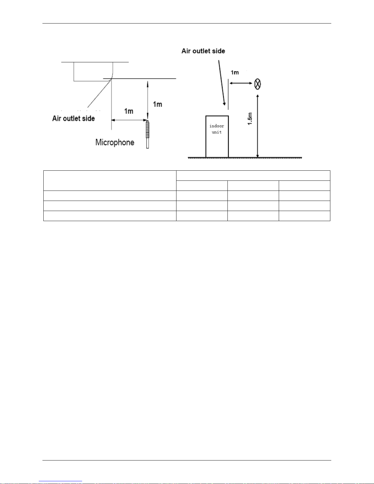
9. Sound Levels
Ceiling Floor
Noise level dB(A)
Model
H M L
MUB-12HRDN1 39.6 36.7 33.1
MUB-12HRDN1-Q 39.6 36.7 33.1
MUB-18HRDN1-Q 44.6 41.8 37.3
Page 28
Exploded View MCAC-UTSM-2008-05
26 Ceiling and Floor Type
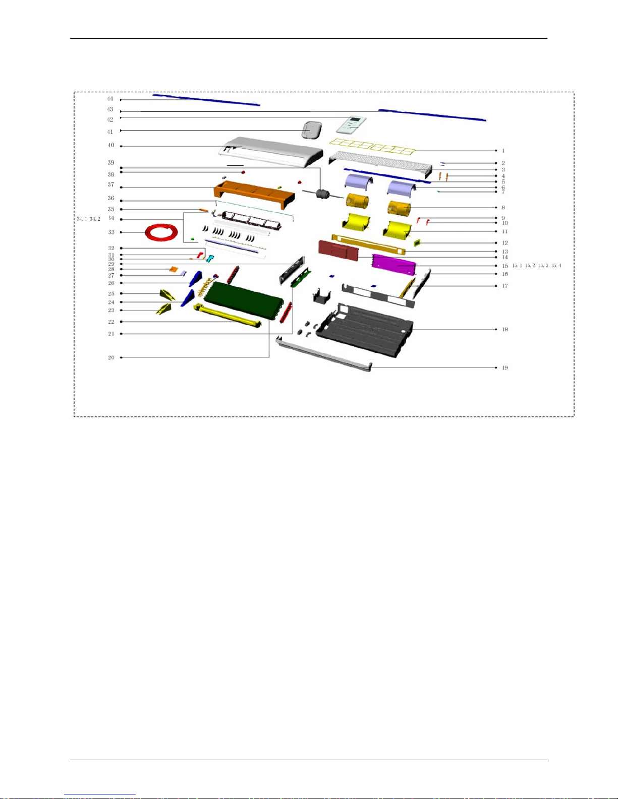
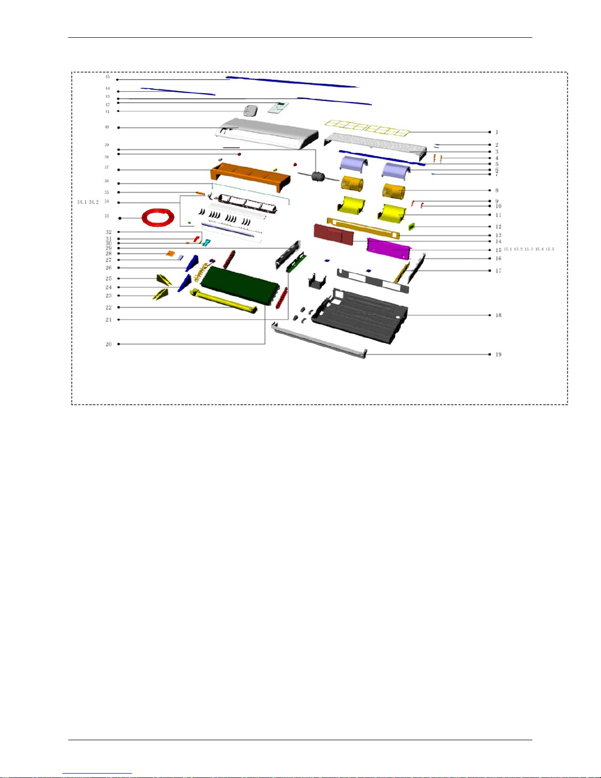
10. Exploded View
10.1 MUB-12HRDN1-Q
Page 29
MCAC-UTSM-2008-05 Exploded View
Ceiling and Floor Type 27
No. Part name Quantity No. Part name Quantity
1 Filter 2 22 Foam ass'y 1
2 Grille clamp 2 23 Foam ass'y 1
3 Grille 1 24 Evaporator Left support 1
4 Grille clamp 2 25 Foam ass'y 1
5 Grille strengthening rib 1 26 Support board 1
6 Volute shell 2 27 Evaporator right clapboard 1
7 Grille lock 1 28 Evaporator left clapboard 1
8 Plastic fan 2 29 Cover 1
9 Motor clamp 1 30 Display panel box 1
10 Motor clamp 1 31 Display board ass'y 1
11 Volute shell 2 32 Manual button 1
12 Board 1 33 Connecting hose ass'y 1
13 Middle beam 1 34 Air outlet ass'y 1
14 E-part box cover 1 34.1 Stepper motor(vertical) 1
15 E-part box ass'y 1 34.2 Stepper motor 1
15.1 Transformer 1 35 Foam 1
15.2 Main controller ass'y 1 36 Drainage pan holder 2
15.3 Wire joint 1 37 Drainage pan ass'y 1
15.4 Motor capacitor 1 38 Plastic cover 1
16 Left cover 1 39 Motor 1
17 Installation board 1 40 Panel ass'y 1
18 Base ass'y 1 41 Installation bracket 1
19 Rear cover 1 42 Remote controller 1
20 Evaporator ass'y 1 43 Temp. sensor ass'y 1
21 Installation board 1 44 Room temp sensor ass'y 1
Page 30
Exploded View MCAC-UTSM-2008-05
28 Ceiling and Floor Type
10.2 MUB-18HRDN1-Q
Page 31

MCAC-UTSM-2008-05 Exploded View
Ceiling and Floor Type 29
No. Part name Quantity No. Part name Quantity
1 Filter 2 22 Foam ass'y 1
2 Grille clamp 2 23 Foam ass'y 1
3 Grille 1 24 Evaporator Left support 1
4 Grille clamp 2 25 Foam ass'y 1
5 Grille strengthening rib 1 26 Support board 1
6 Volute shell 2 27 Evaporator right clapboard 1
7 Grille lock 1 28 Evaporator left clapboard 1
8 Plastic fan 2 29 Cover 1
9 Motor clamp 1 30 Display panel box 1
10 Motor clamp 1 31 Display board ass'y 1
11 Volute shell 2 32 Manual button 1
12 Board 1 33 Connecting hose ass'y 1
13 Middle beam 1 34 Air outlet ass'y 1
14 E-part box cover 1 34.1 Stepper motor(vertical) 1
15 E-part box ass'y 1 34.2 Stepper motor 1
15.1 Transformer 1 35 Foam 1
15.2 Main controller ass'y 1 36 Drainage pan holder 2
15.3 Wire joint, 2p 1 37 Drainage pan ass'y 1
15.4 Wire joint 1 38 Plastic cover 1
15.5 Motor capacitor 1 39 Motor 1
16 Left cover 1 40 Panel ass'y 1
17 Installation board 1 41 Installation bracket 1
18 Base ass'y 1 42 Remote controller 1
19 Rear cover 1 43 Temp. sensor ass'y 1
20 Evaporator ass'y 1 44 Temp. sensor ass'y 1
21 Installation board 1 45 Room temp sensor ass'y 1
Page 32

Exploded View MCAC-UTSM-2008-05
30 Ceiling and Floor Type
10.3 MUB-12HRDN1
Page 33

MCAC-UTSM-2008-05 Exploded View
Ceiling and Floor Type 31
No. Part name Quantity No. Part name Quantity
1 Filter 2 22 Foam ass'y 1
2 Grille clamp 2 23 Evaporator Left support 1
3 Grille 1 24 Foam ass'y 1
4 Grille clamp 2 25 Support board 1
5 Grille strengthening rib 1 26 Evaporator right clapboard 1
6 Volute shell 2 27 Evaporator left clapboard 1
7 Grille lock 1 28 Cover 1
8 Plastic fan 2 29 Display panel box 1
9 Motor clamp 1 30 Display board ass'y 1
10 Motor clamp 1 31 Manual button 1
11 Volute shell 2 32 Air outlet ass'y 1
12 Board 1 33 Stepper motor(vertical) 1
13 Middle beam 1 33.1 Stepper motor 1
14 E-part box cover 1 33.2 Foam 1
15 E-part box ass'y 1 34 Drainage pan holder 2
15.1 Transformer 1 35 Drainage pan ass'y 1
15.2 Main controller ass'y 1 36 Plastic cover 1
15.3 Wire joint 1 37 Motor 1
15.4 Motor capacitor 1 38 Panel ass'y 1
16 Left cover 1 39 Installation bracket 1
17 Installation board 1 40 Remote controller 1
18 Base ass'y 1 41 Temp. sensor ass'y 1
19 Rear cover 1 42 Temp. sensor ass'y 1
20 Evaporator ass'y 1 43 Room temp sensor ass'y 1
21 Installation board 1 44 Foam ass'y 1
Page 34

Accessories MCAC-UTSM-2008-05
32 Ceiling and Floor Type
11. Accessories
Name of accessories Quantity Outline Usage
Owner’s installation/remote controller
manual
1 /
Hook 2
For wall mounting installation
Hanging arm 2
For ceiling installation
Screw bolt with washer 4
For ceiling installation
Remote controller 1
_
Frame 1
_
Mounting screw(ST2.9×10-C-H)
2
_
Alkaline dry batteries (AM4) 2
_
Page 35

MCAC-UTSM-2008-05 Outdoor Units
Outdoor Units 33
Part 3
Outdoor Units
1. Dimensions......................................................................34
2. Service Space..................................................................35
3. Piping Diagrams..............................................................36
4. Wiring Diagrams .............................................................37
5. Electric Characteristics..................................................40
6. Sound Levels...................................................................41
7. Exploded View.................................................................42
8. Operation Limits .............................................................47
9. Troubleshooting..............................................................48
Page 36

Dimensions MCAC-UTSM-2008-05
34 Outdoor Units
1. Dimensions
Model A B C D E F H
MOU-12HDN1 761 530 290 315 270 279 593
MOU-12HDN1-Q 761 530 290 315 270 279 593
MOU-18HDN1-Q 842 560 335 360 312 324 695
Page 37

MCAC-UTSM-2008-05 Service Space
Outdoor Units 35
2. Service Space
Page 38

Piping Diagrams MCAC-UTSM-2008-05
36 Outdoor Units
3. Piping Diagrams
3.1 MOU-12HDN1-Q MOU-12HDN1
Compressor
Outdoor unit
4-way valve
Condenser
Indoor unit
Capillary ass'y
Evaporator
3.2 MOU-18HDN1-Q
Condenser
Compressor
Low pressure switch
Outdoor unit
High pressure
switch
4-way valve
Indoor unit
Capillary
Evaporator
Electronic expansion
valve ass'y
Page 39

MCAC-UTSM-2008-05 Wiring Diagrams
Outdoor Units 37
4. Wiring Diagrams
4.1 MOU-12HDN1-Q
Page 40

Wiring Diagrams MCAC-UTSM-2008-05
38 Outdoor Units
4.2 MOU-18HDN1-Q
Page 41

MCAC-UTSM-2008-05 Wiring Diagrams
Outdoor Units 39
4.3 MOU-12HDN1
Page 42

Electric Characteristics MCAC-UTSM-2008-05
40 Outdoor Units
5. Electric Characteristics
Outdoor Unit Power Supply Compressor OFM
Model
Hz Voltage Min. Max. TOCA MFA RLA kW FLA
MOU-12HDN1 50 220~240V 198 254 20 16 5.3 0.024 0.27
MOU-12HDN1-Q 50 220~240V 198 254 20 16 5.3 0.024 0.27
MOU-18HDN1-Q 50 220~240V 198 254 20 16 8.8 0.053 0.59
Remark:
TOCA: Total Over-current Amps. (A)
MFA: Max. Fuse Amps. (A)
RLA: Rated Locked Amps. (A)
OFM: Outdoor Fan Motor.
FLA: Full Load Amps. (A)
KW: Rated Motor Output (KW)
Page 43

MCAC-UTSM-2008-05 Sound Levels
Outdoor Units 41
6. Sound Levels
Noise level dB(A)
Model
Hi Lo
MOU-12HDN1 48 44
MOU-12HDN1-Q 48 44
MOU-18HDN1-Q 52 47
Page 44

Exploded View MCAC-UTSM-2008-05
42 Outdoor Units
7. Exploded View
7.1 MOU-12HDN1-Q
No. Part name Quantity No. Part name Quantity
1 Top cover 1 14 Drainage pan 1
2 E-part box ass'y 1 15 Big handle 1
2.1 Main controller ass'y 1 16 Discharge temp sensor ass'y 1
2.2 Compressor capacitor 1 17 Condenser ass'y 1
2.3 Radiator 1 17.1 Condenser inlet pipe ass'y 1
3 Grille 1 17.2 Condenser 1
4 Axial flow fan 1 17.3 Condenser outlet pipe 1
5 Left holder 1 18 Room temp sensor ass'y 1
6 Partition board ass'y 1 19 Connect couplings ass'y 1
7 Base ass'y 1 19.1 One way valve 1
8.1 Reactance 1 19.2 Connect couplings 1
8.2 Reactance 1 19.3 Strainer ass'y 1
9 Electric inductance cover ass'y 1 19.4 Four-way electro-magnetic reversing valve 1
10 Sponge 1 20 Temp. sensor ass'y 1
11 Compressor electric heater 1 21 Motor bracket 1
12 Compressor 1 22 Motor 1
13 Right cover 1 23 Front panel 1
Page 45

MCAC-UTSM-2008-05 Exploded View
Outdoor Units 43
7.2 MOU-18HDN1-Q
Page 46

Exploded View MCAC-UTSM-2008-05
44 Outdoor Units
No. Part name Quantity No. Part name Quantity
1 Top cover ass'y 1 13 Compressor 1
2 Rear net frame 1 14 Rear right clapboard ass'y 1
3 E-part box ass'y 1 15 Drainage cover 1
3.1 Inverter radiator 1 16 Big handle 1
3.2 Transformer 1 17 Discharge temp sensor ass'y 1
3.3 Transformer 1 18 Condenser ass'y 1
3.4 Main controller ass'y 1 18.1 Output pipe ass'y 1
3.5 Inverter control Module 1 18.2 Input pipe ass'y 1
3.6 Rectifier 2 18.3 Condenser 1
3.7 Compressor capacitor 1 19 Temp sensor 1
3.8 Power board ass'y 1 20 Connect coupling ass'y 1
3.9 Main controller ass'y 1 20.1 Solenoid 1
3.10 EMC filter 1 20.2 4-way valve 1
3.11 Motor capacitor 1 20.3 Connect coupling 1
3.12 Wire joint 1 20.4 Pressure controller 1
4 Grille 1 20.5 Pressure controller 1
5 Axial flow fan 1 20.6 Electronic expansion valve 1
6 Left holder 1 20.7 EEV solenoid 1
7 Partition board ass'y 1 21 Temp. sensor ass'y 1
8 Base ass'y 1 22 Motor bracket ass'y 1
9 Reactance 1 23 Motor 1
10 Electrical inductance box 1 24 Front panel 1
11 Sponge 1 25 Reactance 1
12 Compressor electric heater 1 26 Reactance 1
Page 47

MCAC-UTSM-2008-05 Exploded View
Outdoor Units 45
7.3 MOU-12HDN1
Page 48

Exploded View MCAC-UTSM-2008-05
46 Outdoor Units
No. Part name Quantity No. Part name Quantity
1 Top cover 1 14 Drainage pan 1
2 E-part box ass'y 1 15 Big handle 1
2.1 Main controller ass'y 1 16 Discharge temp sensor ass'y 1
2.2 Compressor capacitor 1 17 Condenser ass'y 1
2.3 Radiator 1 17.1 Condenser inlet pipe ass'y 1
2.4 Main controller ass'y 1 17.2 Condenser 1
2.4.1 Rectifier 1 17.3 Condenser outlet pipe 1
3 Grille 1 18 Room temp sensor ass'y 1
4 Axial flow fan 1 19 Low pressure valve ass'y 1
5 Left holder 1 19.1 Low pressure valve 1
6 Partition board ass'y 1 19.2 Four-way electro-magnetic reversing valve 1
7 Base ass'y 1 20 High pressure valve ass'y 1
8.1 Reactance 1 20.1 High pressure valve 1
8.2 Reactance 1 20.2 One way valve 1
9 Electric inductance cover ass'y 1 21 Temp. sensor ass'y 1
10 Sponge 1 22 Motor bracket 1
11 Compressor electric heater 1 23 Motor 1
12 Compressor 1 24 Front panel 1
13 Right clapboard 1
Page 49

MCAC-UTSM-2008-05 Operation Limits
Outdoor Units 47
8. Operation Limits
8.1 For 12000Btu/h:
Cooling mode Heating mode
Item
Model
Outdoor Indoor Outdoor Indoor
MOU-12HDN1 (-Q)
21℃~43℃ 17℃~30℃ -5℃~24℃ 17℃~30℃
50
Range for
intermittent operation
Range for intermittent operation
Range for continuous operation
Range for continuous
operation
5
Indoor temperature(℃ WB)
Outdoor temperature(℃ DB)
30
24
20
15
10
5
0
-5
-20
10 15 20 25 30
3025201510
15
20
25
30
35
40
43
Cooling
Heating
Outdoor temperature(℃ WB)
Indoor temperature(℃ DB)
8.2 For 1800Btu/h:
Cooling mode Heating mode
Item
Model
Outdoor Indoor Outdoor Indoor
MOU-18HDN1-Q
-15℃~43℃ 17℃~30℃ -15℃~21℃ 17℃~30℃
17 24 30
43
40
35
30
25
20
15
10
5
0
-5
-15
cooling
Indoor temp.( C)
0
Ambient
temp
.
( C)
0
17 24 30
21
6
-15
Heating
Indoor temp. (° C)
A
m
b
i
e
n
t
t
e
m
p
.
(
°
C
)
Page 50

Troubleshooting MCAC-UTSM-2008-05
48 Outdoor Units
9. Troubleshooting
9.1 Indoor unit malfunction
No Malfunction
Running
lamp
Timer
lamp
Defrosting
lamp
Alarm
lamp
1 Room temperature sensor checking channel is abnormal
☆ × × ×
2 Evaporator sensor checking channel is abnormal
× × ☆ ×
3
In-outdoor unit communication checking channel is
abnormal
× ☆ × ×
4 Water-level switch malfunction
× × × ☆
5 EEPROM malfunction
☆ ☆ × ×
6 IPM module protection
☆ × × ●
7 Condenser sensor checking channel is abnormal
☆ ● × ×
8 Outdoor unit voltage protection
☆ ● × ●
9 Compressor discharge over-temperature protection
☆ × ● ×
10 Outdoor unit over-current protection
☆ ☆ × ☆
(× Extinguish, ☆ Flash at 5Hz, ● On)
Page 51

MCAC-UTSM-2008-05 Troubleshooting
Outdoor Units 49
1. Running lamp flash at 5Hz: Room temperature sensor is abnormal
2. Defrosting lamp flash at 5Hz: Evaporator temperature sensor is abnormal
Running lamp flash at 5Hz
Judge: Room temperature sensor is abnormal
Validate: Check whether the resistance of the
temperature sensor is correct according to
Replace room temperature sensor
No
Replace indoor PCB
Yes
Defrosting lamp flash at 5Hz
Judge: Evaporator temperature sensor is abnormal
Validate: Check whether the resistance of the
temperature sensor is correct according to Annex 1
Replace room temperature sensor
No
Replace indoor PCB
Yes
Page 52

Troubleshooting MCAC-UTSM-2008-05
50 Outdoor Units
3. Timer lamp flash at 5Hz: Communication malfunction between indoor/outdoor units
Timer lamp flash at 5Hz
Communication malfunction between indoor/outdoor units
Judge 3: Check whether the signal wiring between the
indoor and outdoor units is wrong polarity?
Connect the signal wiring correctly
Yes
No
Judge 4: Check whether the signal wiring between the
indoor and outdoor units is broken?
Yes
Replace the broken wiring
No
Judge 2: Check whether the signal wiring is shield cable or
whether the shield cable is earthing
Yes
Adopt the shield cable/ shield cable earthing
No
Indoor or outdoor main board is broken, replace the
main board until the malfunction is disappear
Judge 1: Check whether the indoor unit power is on
Turn on the indoor unit power
No
Yes
Page 53

MCAC-UTSM-2008-05 Troubleshooting
Outdoor Units 51
4. Alarm lamp flash at 5Hz: Water-level switch malfunction
O
K
OK
Alarm lamp flashes at 5Hz
Exist
O
K
Water-level switch Connecting
wire between switch and main
board gets loose
Reconnect and ensure
that the connection is
reliable.
There is something wrong
with the water-level switch
Exist
Replace switch
Chip fault, or chip foot sheds off, or chip is
inverted (correct mode is semicircular bent
alignment)
Error
Reinstall chip, or install other chip
with same model on the faulty unit,
to check whether there is
something wrong with chip.
Main board error:
For example,
getting wet
Replace
main board
OK
Page 54

Troubleshooting MCAC-UTSM-2008-05
52 Outdoor Units
5. Running and Timer lamp flash at 5Hz: EEPROM malfunction
Running and Timer lamp flash at 5Hz
EEPROM malfunction
Judge 1: Check whether the EEPROM is inserted well
Yes
No
Insert the EEPROM well
Replace outdoor main board
Page 55

MCAC-UTSM-2008-05 Troubleshooting
Outdoor Units 53
6. Running lamp flash at 5Hz and Alarm lamp on: IPM protection
Running lamp flash at 5Hz and Alarm lamp on
IPM protection
Check whether the voltage range of P-N on
IPM module is normal?
No
Check whether the input power supply
is correct? 220-240V, 1N, 50Hz
No
Regulate it to correct,
then check whether the
system can work
normally?
Yes
Check whether the power
supply line is connected
correctly and tightly
No
Connect it correctly and
tightly, check ok or not?
No
Yes
Check whether the lines in
E-part box are connected tightly
No
Connect it tightly,
check ok or not?
No
Yes
Check whether the single-phase bridge is
normal? Use the multimeter to measure the
resistance between each two terminals, check
whether there is the condition that value of
resistance is 0
Yes
Replace the
single-phase bridge
No
No
Check whether the connecting line
of every reactor is normal? If the
line is broken, the resistance of the
two ports is ∞
No
Replace the
connecting line
Yes
Check whether the connecting line
between main board and the IPM
module is connected tightly
Yes
Check whether the connecting
line of the compressor is
connected correctly or tightly
Yes
Replace the IPM module, check
whether the system can work
normally?
No
Replace the main board, check
whether the system can work
normally?
Yes
Trouble is solved
No
Replace the compressor, check
whether the system can work
normally?
Connect it tightly,
check ok or not?
No
Connect it well,
check ok or not?
No
Yes
Trouble is solved
No
No
Yes
Trouble is solved
Yes
Check whether the fuse on
the power board is normal?
No
Replace with
the same model
fuse
Yes
Replace the power board
Page 56

Troubleshooting MCAC-UTSM-2008-05
54 Outdoor Units
7. Running lamp flash at 5Hz and Timer lamp on: Condenser temperature sensor is malfunction
Running lamp flash at 5Hz and Timer lamp on
Check whether the wiring of the Condenser temperature sensor
is break off
Replace outdoor main board
Judge : Condenser temperature sensor is malfunction
Connect the wiring well
Yes
No
Check whether the resistance of Condenser temperature sensor
is wrong refer to the Annex 1
Yes
Replace Condenser
temperature sensor
No
Page 57

MCAC-UTSM-2008-05 Troubleshooting
Outdoor Units 55
8. Running lamp flash at 5Hz, Timer and Alarm lamp on: Outdoor unit voltage protection
Running lamp flash at 5Hz, Timer and Alarm lamp on
Outdoor unit voltage protection
Check the voltage of outdoor unit power supply, whether the
voltage between L1 and N is about 198-254V
No
Replace the power board, then check whether the system can run normally
Check the power supply
Yes
Replace outdoor main board
Yes
Trouble is solved
No
Page 58

Troubleshooting MCAC-UTSM-2008-05
56 Outdoor Units
9. Running lamp flash at 5Hz and Defrosting lamp on: Compressor discharge temperature protection
Running lamp flash at 5Hz and Defrosting lamp on
Compressor discharge temperature protection
Check whether the compressor discharge temp. more than 115°C ?
No
Check whether the wiring connection is right
between compressor discharge temp.
sensor and PCB according to wiring
diagrams
Yes
Validate: Check whether the resistance of compressor
discharge temp. sensor is right refer to the Annex 2
No
Correct the wiring connection
Yes
Replace outdoor main board
Judge: The discharge temp. sensor is broken
No
Replace the compressor
discharge temp. sensor
Check whether the refrigerant is leakage
Stop leaking and add refrigerant
Yes
Yes
Page 59

MCAC-UTSM-2008-05 Troubleshooting
Outdoor Units 57
10. Running lamp 、Timer lamp and Alarm lamp flash at 5Hz: Outdoor unit current protection
Running lamp 、Timer lamp and Alarm lamp flash at 5Hz
Outdoor unit current protection
Judge 1: Check whether the input current of the power supply wire
is more than 16A.
Check whether the refrigerant system is ok
Yes
Judge 2: Check whether the outdoor ambient temperature is too high
Yes
Stop the unit
Replace outdoor main board
No
No
Judge 3: Check whether the outdoor unit is bad ventilation
Yes
Make the outdoor unit ventilate well
No
Judge 4: Check whether the heat exchanger is dirty
Yes
Clean the heat exchanger
No
Judge 5: The refrigerant pipe is blocked
Yes
Drop refrigerant, then use the high pressure
nitrogen or refrigerant to blow pipe,
vacuumize and add the refrigerant again
Page 60

Troubleshooting MCAC-UTSM-2008-05
58 Outdoor Units
9.2 Outdoor unit malfunctions:
12000Btu/h: Its malfunctions are displayed on the indoor units’ indicator.
18000Btu/h: Its malfunctions are displayed on the outdoor units’ digital tube.
Display Malfunction or Protection
E0 EEPROM malfunction
E2 Communication malfunction between indoor/outdoor units
E3 Communication malfunction in outdoor PCB
E4 Outdoor temperature sensors malfunction
E5 Compressor voltage protection
P1 High pressure protection
P2 Low pressure protection
P3 Compressor current protection
P4 Compressor discharge temperature protection
P5 Condenser high temperature protection
P6 IPM protection
1. E0 malfunction
LED indicates E0
EEPROM malfunction
Check whether the EEPROM is inserted well
Yes
No
Insert the EEPROM well
Replace outdoor main board
Page 61

MCAC-UTSM-2008-05 Troubleshooting
Outdoor Units 59
2. E2 malfunction
LED indicates E2
Communication malfunction between indoor/outdoor units
Judge 3: Check whether the signal wiring between the
indoor and outdoor units is wrong polarity?
Connect the signal wiring correctly
Yes
No
Judge 4: Check whether the signal wiring between the
indoor and outdoor units is broken?
Yes
Replace the broken wiring
No
Judge 2: Check whether the signal wiring is shield cable or
whether the shield cable is earthing
Yes
Adopt the shield cable/ shield cable earthing
No
Indoor or outdoor main board is broken, replace the
main board until the malfunction is disappear
Judge 1: Check whether the indoor unit power is on
Turn on the indoor unit power
No
Yes
Page 62

Troubleshooting MCAC-UTSM-2008-05
60 Outdoor Units
3. E3 malfunction
LED indicates E3
Communication malfunction in outdoor PCB
Check whether the indicator lights LED1 on the main board are flashing Replace the outdoor main board
Yes
Check whether the connecting wiring between the IPM module and
the CN4 on the main board is break off
Insert the connecting wiring well
over again
Yes
No
Disconnect the connecting wiring between the IPM module and the
CN4 on the main board, use the multimeter to measure the voltage
between the IPM module CN1 port’s 3 and 4 pillar, check whether it is
5V, (the third pillar on the main board labels +5V)
No
Replace outdoor main board
Yes
No
Insert the connecting wiring well over again
Check whether the connecting wiring between the IPM module
positive pole and the CN12 on the power board is break off
Yes
No
No
Replace the IPM module
Use the multimeter to measure whether the voltage between the
CN12 and the CN13 on the power board is between
+(198V~254)V
Yes
Replace the power board
Check whether the connecting wiring between the IPM module
negative pole and the CN13 on the power board is break off
No
Insert the connecting wiring well over again
Yes
Page 63

MCAC-UTSM-2008-05 Troubleshooting
Outdoor Units 61
4. E4 malfunction
LED indicates E4
Check whether the wiring of the outdoor ambient temperature
sensor (T4) is break off
Replace outdoor main board
Judge 1: Outdoor ambient temp. sensor (T4) is malfunction
Connect the wiring well
Yes
No
Check whether the resistance of outdoor ambient temperature
sensor (T4) is wrong refer to the Annex 1
Yes
Replace outdoor ambient
temperature sensor (T4)
No
Page 64

Troubleshooting MCAC-UTSM-2008-05
62 Outdoor Units
5. E5 malfunction
LED indicates E5
Outdoor unit voltage protection
Check the voltage of outdoor unit power supply, whether the
voltage between L1 and N is about 198-254V
No
Replace the power board, then check whether the system can run normally
Check the power supply
Yes
Replace outdoor main board
Yes
Trouble is solved
No
Page 65

MCAC-UTSM-2008-05 Troubleshooting
Outdoor Units 63
6. P1 malfunction
LED indicates P1
High pressure protection
Judge 1: Whether the wiring between the high pressure switch
and main control board is connected well or correctly
Judge 2: Whether the high pressure switch is broken
Yes
No
Connect it well
Validate: Short connect the high pressure switch
socket, check whether the system can run normally
Yes
Replace high pressure switch
No
Check whether the refrigerant system is ok
Replace outdoor main board
No
Judge 3: Check whether the outdoor ambient temperature is too high
Yes
Stop the unit
No
Judge 4: Check whether the outdoor unit is bad ventilation
Yes
Make the outdoor unit ventilate well
No
Judge 5: Check whether the heat exchanger is dirty
Yes
Clean the heat exchanger
No
Judge 6: Check whether the refrigerant pipe is blocked
Yes
Drop refrigerant, then use the high pressure
nitrogen or refrigerant to blow pipe,
vacuumize and add the refrigerant again
Page 66

Troubleshooting MCAC-UTSM-2008-05
64 Outdoor Units
7. P2 malfunction
LED indicates P2
Low pressure protection
Judge 1: The wiring between the low pressure switch and main
control board is connected well or correctly
Judge 2: Whether the low pressure switch is broken
Connect it well
Validate: Short connect the low pressure switch
socket, check whether the system can run normally
Check whether the refrigerant system is ok
Yes
No
Judge 3: Check whether the outdoor ambient temperature is too low
Yes
Stop the unit
No
Judge 4: The refrigerant of the system is leakage
Yes
Validate: Connect the pressure gauge to the gauge joint of the
system, check whether the pressure is lower than 0.15MPa
Leak hunting: charge nitrogen or
refrigerant to the system, if the leakage is
serious, there will be distinct gas leakage
“cici” sound; if the leakage is little, use
the suds(mixture of water and abluent is
also ok, if it can make bubble) or
electronic leak detector.
Judge 5: The refrigerant pipe is blocked
Yes
Drop refrigerant, then use the high pressure
nitrogen or refrigerant to blow pipe, vacuumize
and add the refrigerant again
No
Replace outdoor main board
No
No
Yes
Replace low pressure switch
Page 67

MCAC-UTSM-2008-05 Troubleshooting
Outdoor Units 65
8. P3 malfunction
LED indicates P3
Outdoor unit current protection
Judge 1: Check whether the input current of the power supply wire
is more than 18A
Check whether the refrigerant system is ok
Yes
Judge 2: Check whether the outdoor ambient temperature is too high
Yes
Stop the unit
Replace outdoor main board
No
No
Judge 3: Check whether the outdoor unit is bad ventilation
Yes
Make the outdoor unit ventilate well
No
Judge 4: Check whether the heat exchanger is dirty
Yes
Clean the heat exchanger
No
Judge 5: The refrigerant pipe is blocked
Yes
Drop refrigerant, then use the high pressure
nitrogen or refrigerant to blow pipe,
vacuumize and add the refrigerant again
Page 68

Troubleshooting MCAC-UTSM-2008-05
66 Outdoor Units
9. P4 malfunction
LED indicates P4
Compressor discharge temperature protection
Check whether the compressor discharge temp. more than 115°C ?
No
Check whether the wiring connection is right
between compressor discharge temp.
sensor and PCB according to wiring
diagrams
Yes
Validate: Check whether the resistance of compressor
discharge temp. sensor is right refer to the Annex 2
No
Correct the wiring connection
Yes
Replace outdoor main board
Judge: The discharge temp. sensor is broken
No
Replace the compressor
discharge temp. sensor
Check whether the refrigerant is leakage
Stop leaking and add refrigerant
Yes
Yes
Page 69

MCAC-UTSM-2008-05 Troubleshooting
Outdoor Units 67
10. P5 malfunction
.
LED indicates P5
Condenser high temperature protection
Check whether the condenser temperature is more than 65°C
No
Check whether the resistance of condenser
temp. sensor is correct refer to the Annex 1
Yes
Replace outdoor main board
No
Replace the temperature sensor
Yes
Judge1: The outdoor temp. is too high(more than 43 )℃
Replace outdoor main board
No
Judge 2: Check whether the heat exchanger is dirty
No
Judge 3: The refrigerant pipe is blocked
Clean the heat exchanger
Yes
Yes
Drop refrigerant, then use the high pressure
nitrogen or refrigerant to blow pipe,
vacuumize and add the refrigerant again
Yes
Stop the unit
No
Page 70

Troubleshooting MCAC-UTSM-2008-05
68 Outdoor Units
11. P6 malfunction
LED indicates P6
IPM protection
Check whether the voltage range of P-N on
IPM module is normal?
No
Check whether the input power supply
is correct? 220-240V, 1N, 50Hz
No
Regulate it to correct,
then check whether the
system can work
normally?
Yes
Check whether the power
supply line is connected
correctly and tightly
No
Connect it correctly and
tightly, check ok or not?
No
Yes
Check whether the lines in
E-part box are connected tightly
No
Connect it tightly,
check ok or not?
No
Yes
Check whether the single-phase bridge is
normal? Use the multimeter to measure the
resistance between each two terminals, check
whether there is the condition that value of
resistance is 0
Yes
Replace the
single-phase bridge
No
No
Check whether the connecting line
of every reactor is normal? If the
line is broken, the resistance of the
two ports is ∞
No
Replace the
connecting line
Yes
Check whether the connecting line
between main board and the IPM
module is connected tightly
Yes
Check whether the connecting
line of the compressor is
connected correctly or tightly
Yes
Replace the IPM module, check
whether the system can work
normally?
No
Replace the main board, check
whether the system can work
normally?
Yes
Trouble is solved
No
Replace the compressor, check
whether the system can work
normally?
Connect it tightly,
check ok or not?
No
Connect it well,
check ok or not?
No
Yes
Trouble is solved
No
No
Yes
Trouble is solved
Yes
Check whether the fuse on
the power board is normal?
No
Replace with
the same model
fuse
Yes
Replace the power board
Page 71

MCAC-UTSM-2008-05 Troubleshooting
Outdoor Units 69
Annex 1
Temp
Resistance(KΩ)
Resist.tol %
Temp.tol℃
(℃)
Rmax
R(t)Normal
Rmin MAX(+) MIN(-) MAX(+) MIN(-)
-20 116.539 106.732 96.920 9.19 9.19 1.59 1.59
-19 110.231 100.552 91.451 9.63 9.05 1.57 1.57
-18 103.743 94.769 86.328 9.47 8.91 1.56 1.55
-17 97.673 89.353 81.525 9.31 8.76 1.54 1.54
-16 91.990 84.278 77.017 9.15 8.62 1.53 1.52
-15 86.669 79.521 72.788 8.99 8.47 1.51 1.50
-14 81.684 75.059 68.815 8.83 8.32 1.49 1.48
-13 77.013 70.873 65.083 8.66 8.17 1.47 1.47
-12 72.632 66.943 61.574 8.50 8.02 1.45 1.45
-11 68.523 63.252 58.274 8.33 7.87 1.44 1.43
-10 64.668 59.784 55.169 8.17 7.72 1.42 1.41
-9 61.048 56.524 52.246 8.00 7.57 1.40 1.39
-8 57.649 53.458 49.492 7.84 7.42 1.38 1.37
-7 54.456 50.575 46.899 7.67 7.27 1.35 1.35
-6 51.456 47.862 44.455 7.51 7.12 1.33 1.32
-5 48.636 45.308 42.150 7.35 6.97 1.31 1.30
-4 45.984 42.903 39.977 7.18 6.82 1.29 1.28
-3 43.490 40.638 37.927 7.02 6.67 1.27 1.26
-2 41.144 38.504 35.992 6.86 6.52 1.25 1.24
-1 38.935 36.492 34.165 6.70 6.38 1.23 1.21
0 36.857 34.596 32.440 6.53 6.23 1.21 1.19
1 34.898 32.807 30.810 6.38 6.09 1.18 1.17
2 33.055 31.120 29.271 6.22 5.94 1.16 1.15
3 31.317 29.528 27.815 6.06 5.80 1.14 1.12
4 29.681 28.026 26.440 5.90 5.66 1.12 1.10
5 28.138 26.608 25.140 5.75 5.52 1.10 1.08
6 26.682 25.268 23.909 5.60 5.38 1.07 1.06
7 25.310 24.003 22.745 5.45 5.24 1.05 1.03
8 24.016 22.808 21.644 5.30 5.10 1.03 1.01
9 22.794 21.678 20.601 5.15 4.97 1.01 0.99
10 21.641 20.610 19.614 5.00 4.83 0.99 0.97
11 20.553 19.601 18.680 4.86 4.70 0.96 0.94
12 19.525 18.646 17.794 4.71 4.57 0.94 0.92
13 18.554 17.743 16.955 4.57 4.44 0.92 0.90
14 17.636 16.888 16.160 4.43 4.31 0.90 0.88
15 16.769 16.079 15.406 4.29 4.19 0.88 0.85
16 15.949 15.313 14.691 4.15 4.06 0.86 0.83
17 15.174 14.588 14.014 4.02 3.94 0.84 0.81
Page 72

Troubleshooting MCAC-UTSM-2008-05
70 Outdoor Units
Temp
Resistance(KΩ)
Resist.tol %
Temp.tol℃
(℃)
Rmax
R(t)Normal
Rmin MAX(+) MIN(-) MAX(+) MIN(-)
18 14.442 13.902 13.372 3.89 3.81 0.81 0.79
19 13.748 13.251 12.762 3.75 3.69 0.79 0.76
20 13.093 12.635 12.183 3.62 3.57 0.77 0.74
21 12.471 12.050 11.634 3.50 3.46 0.75 0.72
22 11.883 11.496 11.112 3.37 3.34 0.73 0.70
23 11.327 10.971 10.617 3.25 3.23 0.71 0.68
24 10.800 10.473 10.147 3.12 3.11 0.69 0.66
25 10.300 10.000 9.700 3.00 3.00 0.67 0.63
26 9.848 9.551 9.255 3.11 3.10 0.69 0.66
27 9.418 9.125 8.834 3.21 3.19 0.72 0.69
28 9.010 8.721 8.434 3.31 3.29 0.75 0.71
29 8.621 8.337 8.055 3.41 3.38 0.77 0.74
30 8.252 7.972 7.695 3.51 3.47 0.80 0.77
31 7.900 7.625 7.353 3.61 3.57 0.83 0.79
32 7.566 7.296 7.029 3.70 3.66 0.85 0.82
33 7.247 6.982 6.721 3.80 3.74 0.88 0.84
34 6.944 6.684 6.428 3.89 3.83 0.91 0.87
35 6.656 6.401 6.150 3.98 3.92 0.93 0.90
36 6.381 6.131 5.886 4.08 4.00 0.96 0.93
37 6.119 5.874 5.634 4.17 4.09 0.98 0.95
38 5.870 5.630 5.395 4.26 4.17 1.01 0.98
39 5.631 5.397 5.167 4.34 4.26 1.03 1.01
40 5.404 5.175 4.951 4.43 4.34 1.06 1.03
41 5.188 4.964 4.745 4.52 4.42 1.09 1.06
42 4.982 4.763 4.549 4.60 4.50 1.12 1.09
43 4.785 4.571 4.362 4.69 4.58 1.14 1.12
44 4.596 4.387 4.183 4.77 4.66 1.17 1.14
45 4.417 4.213 4.014 4.85 4.74 1.19 1.17
46 4.246 4.046 3.851 4.93 4.81 1.22 1.20
47 4.082 3.887 3.697 5.02 4.89 1.25 1.23
48 3.925 3.735 3.550 5.10 4.97 1.28 1.25
49 3.776 3.590 3.409 5.18 5.04 1.30 1.28
50 3.632 3.451 3.274 5.25 5.12 1.33 1.30
51 3.495 3.318 3.146 5.33 5.19 1.35 1.33
52 3.363 3.191 3.023 5.41 5.26 1.41 1.36
53 3.237 3.069 2.905 5.49 5.34 1.43 1.38
54 3.116 2.952 2.793 5.56 5.41 1.46 1.41
55 3.001 2.841 2.685 5.64 5.48 1.48 1.44
56 2.890 2.734 2.582 5.71 5.55 1.51 1.46
57 2.784 2.632 2.484 5.79 5.62 1.54 1.49
Page 73

MCAC-UTSM-2008-05 Troubleshooting
Outdoor Units 71
Temp
Resistance(KΩ)
Resist.tol %
Temp.tol℃
(℃)
Rmax
R(t)Normal
Rmin MAX(+) MIN(-) MAX(+) MIN(-)
58 2.682 2.534 2.390 5.86 5.69 1.56 1.52
59 2.585 2.440 2.299 5.93 5.76 1.59 1.54
60 2.491 2.350 2.213 6.01 5.83 1.62 1.57
61 2.401 2.264 2.130 6.08 5.90 1.64 1.60
62 2.315 2.181 2.051 6.15 5.96 1.67 1.62
63 2.233 2.102 1.975 6.22 6.03 1.70 1.65
64 2.154 2.026 1.903 6.29 6.10 1.72 1.68
65 2.077 1.953 1.833 6.36 6.16 1.75 1.70
66 2.004 1.883 1.766 6.42 6.23 1.77 1.73
67 1.934 1.816 1.702 6.49 6.29 1.80 1.76
68 1.867 1.752 1.641 6.56 6.35 1.83 1.78
69 1.802 1.690 1.582 6.62 6.41 1.85 1.81
70 1.740 1.631 1.525 6.69 6.48 1.88 1.84
71 1.680 1.574 1.471 6.75 6.54 1.91 1.86
72 1.622 1.519 1.419 6.82 6.60 1.93 1.89
73 1.567 1.466 1.369 6.88 6.66 1.96 1.92
74 1.514 1.416 1.321 6.94 6.71 1.98 1.94
75 1.463 1.367 1.275 7.00 6.77 2.01 1.97
76 1.414 1.321 1.230 7.06 6.83 2.04 2.00
77 1.367 1.276 1.188 7.12 6.88 2.06 2.02
78 1.321 1.233 1.147 7.17 6.94 2.09 2.05
79 1.277 1.191 1.108 7.23 6.99 2.12 2.08
80 1.235 1.151 1.070 7.28 7.04 2.14 2.11
81 1.195 1.113 1.034 7.33 7.09 2.17 2.13
82 1.156 1.076 0.999 7.39 7.14 2.20 2.16
83 1.118 1.041 0.966 7.44 7.18 2.22 2.19
84 1.082 1.007 0.934 7.48 7.23 2.25 2.21
85 1.047 0.974 0.903 7.53 7.27 2.27 2.24
86 1.014 0.942 0.874 7.57 7.31 2.30 2.27
87 0.982 0.912 0.845 7.62 7.35 2.33 2.29
88 0.951 0.883 0.818 7.66 7.39 2.35 2.32
89 0.921 0.855 0.791 7.69 7.43 2.38 2.35
90 0.892 0.828 0.766 7.73 7.46 2.41 2.37
91 0.864 0.802 0.742 7.76 7.49 2.43 2.40
92 0.838 0.777 0.719 7.80 7.52 2.46 2.43
93 0.812 0.753 0.696 7.82 7.54 2.48 2.45
94 0.787 0.730 0.675 7.85 7.57 2.51 2.48
95 0.763 0.708 0.654 7.87 7.59 2.54 2.51
96 0.740 0.686 0.634 7.89 7.61 2.56 2.53
97 0.718 0.666 0.615 7.91 7.62 2.59 2.56
Page 74

Troubleshooting MCAC-UTSM-2008-05
72 Outdoor Units
Temp
Resistance(KΩ)
Resist.tol %
Temp.tol℃
(℃)
Rmax
R(t)Normal
Rmin MAX(+) MIN(-) MAX(+) MIN(-)
98 0.697 0.646 0.597 7.93 7.63 2.62 2.59
99 0.677 0.627 0.579 7.94 7.64 2.64 2.61
100 0.657 0.609 0.562 7.94 7.65 2.67 2.64
101 0.638 0.591 0.546 7.95 7.65 2.70 2.67
102 0.620 0.574 0.530 7.95 7.65 2.72 2.69
103 0.602 0.558 0.515 7.94 7.64 2.75 2.72
104 0.585 0.542 0.501 7.94 7.63 2.77 2.75
105 0.569 0.527 0.485 7.92 7.92 2.80 2.77
Page 75

MCAC-UTSM-2008-05 Troubleshooting
Outdoor Units 73
Annex 2
Unit: ℃---K Discharge temp. sensor table
-20 542.7 20 68.66 60 13.59 100 3.702
-19 511.9 21 65.62 61 13.11 101 3.595
-18 483 22 62.73 62 12.65 102 3.492
-17 455.9 23 59.98 63 12.21 103 3.392
-16 430.5 24 57.37 64 11.79 104 3.296
-15 406.7 25 54.89 65 11.38 105 3.203
-14 384.3 26 52.53 66 10.99 106 3.113
-13 363.3 27 50.28 67 10.61 107 3.025
-12 343.6 28 48.14 68 10.25 108 2.941
-11 325.1 29 46.11 69 9.902 109 2.86
-10 307.7 30 44.17 70 9.569 110 2.781
-9 291.3 31 42.33 71 9.248 111 2.704
-8 275.9 32 40.57 72 8.94 112 2.63
-7 261.4 33 38.89 73 8.643 113 2.559
-6 247.8 34 37.3 74 8.358 114 2.489
-5 234.9 35 35.78 75 8.084 115 2.422
-4 222.8 36 34.32 76 7.82 116 2.357
-3 211.4 37 32.94 77 7.566 117 2.294
-2 200.7 38 31.62 78 7.321 118 2.233
-1 190.5 39 30.36 79 7.086 119 2.174
0 180.9 40 29.15 80 6.859 120 2.117
1 171.9 41 28 81 6.641 121 2.061
2 163.3 42 26.9 82 6.43 122 2.007
3 155.2 43 25.86 83 6.228 123 1.955
4 147.6 44 24.85 84 6.033 124 1.905
5 140.4 45 23.89 85 5.844 125 1.856
6 133.5 46 22.89 86 5.663 126 1.808
7 127.1 47 22.1 87 5.488 127 1.762
8 121 48 21.26 88 5.32 128 1.717
9 115.2 49 20.46 89 5.157 129 1.674
10 109.8 50 19.69 90 5 130 1.632
11 104.6 51 18.96 91 4.849
12 99.69 52 18.26 92 4.703
13 95.05 53 17.58 93 4.562
14 90.66 54 16.94 94 4.426
15 86.49 55 16.32 95 4.294 B(25/50)=3950K
16 82.54 56 15.73 96 4.167
17 78.79 57 15.16 97 4.045
R(90℃)=5KΩ±3%
18 75.24 58 14.62 98 3.927
19 71.86 59 14.09 99 3.812
Page 76

Installation Place MCAC-UTSM-2008-05
74 Installation
Part 4
Installation
1. Installation Place.........................................................75
2. Installation of Indoor Unit ..........................................76
3. Installation of Outdoor Unit .......................................83
4. Refrigerant Piping Connection..................................85
5. Connect the Drain Pipe ..............................................92
6. Wiring...........................................................................94
7. Test Operation.............................................................98
Page 77

MCAC-UTSM-2008-05 Installation Place
Installation 75
1. Installation Place
1.1 The indoor Unit
1) There is enough room for installation and maintenance.
2) The ceiling is horizontal, and its structure can endure the weight of the indoor unit.
3) The air outlet and the air inlet are not impeded, and the influence of external air is the least.
4) The air flow can reach throughout the room.
5) The connecting pipe and drainpipe could be extracted out easily.
6) There is no direct radiation from heaters Test operation.
1.2 The Outdoor Unit
1) There is enough room for installation and maintenance.
2) The air outlet and the air inlet are not impeded, and can not be reached by strong wind.
3) The place is dry and ventilative.
4) The support is flat and horizontal and can stand the weight of the outdoor unit. And no additional noise
or vibration.
5) Your neighborhood will not feel uncomfortable with the noise or expelled air.
6) There is no leakage of combustible gas.
7) It is easy to install the connecting pipe or cables.
Caution:
Location in the following places may cause malfunction of the machine. (If unavoidable, please consult your
local dealer.)
a. There exists petrolatum.
b. There is salty air surrounding (near the coast).
c. There is caustic gas (the sulfide, for example) existing in the air (near a hot spring).
d. The Volt vibrates violently (in the factories).
e. In buses or cabinets.
f. In kitchen where it is full of oil gas.
g. There is strong electromagnetic wave existing.
h. There are inflammable materials or gas.
i. There is acid or alkaline liquid evaporating.
j. Other special conditions
1.3 Notes before Installation
1) Select the correct carry-in path.
2) Move this unit as originally packaged as possible.
3) If the air conditioner is installed on a metal part of the building, it must be electrically insulated according
to the relevant standards to electrical appliances.
Page 78

Installation of Indoor Unit MCAC-UTSM-2008-05
76 Installation
2. Installation of Indoor Unit
2.1 Service Space
Installing Ø10 hanging screw bolts. (4 bolts)
1. Please refer to the following figures for the distance measurement between the screw bolts.
2. Please install with Ø10 hanging screw bolts.
3. The handling to the ceiling varies from the constructions, consult the construction personnels for the
specific procedures.
1) The size of the ceiling to be handled------ Do keep the ceiling flat. Consolidate the roof beam for
possible vibration.
2) Cut off the roof beam.
3) Strengthen the place that has been cut off, and consolidate the roof beam.
4. Carry out the pipe and line operation in the ceiling after finishing the installation of the main body. While
choosing where to start the operation, determine the direction of the pipes to be drawn out. Especially in
case there is a ceiling, position the refrigerant pipes, drain pipes, indoor & outdoor lines to the
connection places before hanging up the machine.
5. The installation of hanging screw bolts.
Wooden construction:
Put the square timber traversely over the roof beam, then install the hanging screw bolts.
Page 79

MCAC-UTSM-2008-05 Installation of Indoor Unit
Installation 77
New concrete bricks:
Inlaying or embedding the screw bolts.
For original concrete bricks:
Install the hanging hook with expansible bolt into the concrete deep to 45~50mm to prevent loose.
Steel for beam structure:
Install and use directly the supporting angle steel.
Page 80

Installation of Indoor Unit MCAC-UTSM-2008-05
78 Installation
2.2 Ceiling Installation:
1. Remove the side board and the grille.
Page 81

MCAC-UTSM-2008-05 Installation of Indoor Unit
Installation 79
2. Cut a gap on the grill.
3. Local the hanging arm on the hanging screw bolt.
Prepare the mounting bolts on the unit.
Page 82

Installation of Indoor Unit MCAC-UTSM-2008-05
80 Installation
4. Hang the unit on the hanging arm by sliding backward. Securely tighten the mounting bolts on both sides.
Note:
The pipe must cross the gap which is cut on the grill in step two.
Page 83

MCAC-UTSM-2008-05 Installation of Indoor Unit
Installation 81
2.3 Wall Mounting Installation:
Page 84

Installation of Indoor Unit MCAC-UTSM-2008-05
82 Installation
1. Fix the hook with tapping screw onto the wall.
2. Hang the indoor unit on the hook.
Page 85

MCAC-UTSM-2008-05 Installation of Outdoor Unit
Installation 83
3. Installation of Outdoor Unit
Caution:
1) Keep this unit away from direct radiation of the sun or other heaters. If unavoidable, please cover it with
a shelter.
2) In places near coast or with a high attitude where the wind is strong, please install the outdoor unit
against the wall to ensure normal performance.
3) Use a baffle when necessary.
4) In the case of extremely strong wind, please prevent the air from flowing backwards into the outdoor
unit.
5) Locate the outdoor unit as close to the indoor unit as possible.
6) The minimum distance between the outdoor unit and obstacles described in the installation chart does not
mean that the same is applicable to the situation of an airtight. Leave open two of three directions M, N, P.
3.1 Necessary Room for Installation and Maintenance.
If possible, please remove the obstacles nearby to prevent the performance from being impeded by too little
of air circulation. Leave open two of the three directions (M, N, P).
Page 86

Installation of Outdoor Unit MCAC-UTSM-2008-05
84 Installation
3.2 Moving and Installing
1) Since the gravity center of the unit is not at its physical center, so please be careful when lifting it with a
sling.
2) Never hold the inlet of the outdoor unit to prevent it from deforming.
3) Do not touch the fan with hands or other objects.
4) Do not lean it more than 45, and do not lay it sidelong.
5) Make concrete foundation according to the specifications of the outdoor units. (Refer to Fig.7-5)
6) Fasten the feet of this unit with bolts firmly to prevent it from collapsing in case of earthquake or strong
wind. (Refer to Fig.7-5)
Page 87

MCAC-UTSM-2008-05 Refrigerant Piping Connection
Installation 85
4. Refrigerant Piping Connection
Caution:
For your safety, always wear safety eye wear and work gloves when connecting the pipes.
4.1 For MOU-12HDN1-Q and MOU-18HDN1-Q
Remove the water tray before performing the connection.
Page 88

Refrigerant Piping Connection MCAC-UTSM-2008-05
86 Installation
To connect the couplings:
Step 1: Ensure that the handle on the male coupling is in a reclined position away from the mating male
coupling.
Step 2: Retract the “Release Sleeve” on female coupling, insert the male coupling located on the indoor unit
into the female coupling.
Step 3:
Release the “Release Sleeve” to the lock the male coupling into places.
Step 4: Fold the male coupling handle towards the female coupling half and push until the handle seals
behind the “Release Sleeve” and flat against the entire coupling assembly.
Page 89

MCAC-UTSM-2008-05 Refrigerant Piping Connection
Installation 87
4.2 For MOU-12HDN1
Check whether the height drop between the indoor unit and outdoor unit, the length of refrigerant pipe, and
the number of the bends meet the following requirements:
Model MOU-12HDN1
When outdoor
unit is top
5
The max height
drop(m)
When outdoor unit is bottom 5
The length of refrigerant pipe(m) 10
The number of bends 5
4.2.1 The Procedure of Connecting Pipes
Caution:
z
All field piping must be provided by a licensed refrigeration technician and must comply with the
relevant local and national codes.
z Do not let air, dust, or other impurities fall in the pipe system during the time of installation.
z The connecting pipe should not be installed until the indoor and outdoor units have been fixed already.
z Keep the connecting pipe dry, and do not let moisture in during installation.
z Execute heat insulation work completely on both sides of the gas piping and the liquid piping. Otherwise,
this can sometimes result in water leakage.
1. Drill a hole in the wall (suitable just for the size of the wall conduit), then set on the fittings such as
the wall conduit and its cover.
2. Bind the connecting pipe and the cables together tightly with binding tapes.
3. Pass the bound connecting pipe through the wall conduct from outside. Be careful of the pipe
allocation to do on damage to the tubing.
4. Connect the pipes. Refer to "How to Connect the pipes" for details.
5. Expel the air with a vacuum pump. Refer to "How to expel the air with a vacuum pump" for details.
6. open the stop values of the outdoor unit to make the refrigerant pipe connecting the indoor unit with
the outdoor unit in fluent flow.
7. Check the leakage. Check all the joints with the leak detector or soap water.
8. Cover the joints of the connecting pipe with the soundproof / insulating sheath (fittings), and bind it
well with the tapes to prevent leakage.
Caution:
Be sure to with insulating materials cover all the exposed parts of the flare pipe joints and refrigerant
pipe on the liquid-side and the gas-side. Ensure that there is no gap between them.
Incomplete insulation may cause water condensation.
Page 90

Refrigerant Piping Connection MCAC-UTSM-2008-05
88 Installation
How to connect the pipes
1. Flaring:
Cut a pipe with a pipe cutter.
Insert a flare nut into a pipe and flare the pipe.
Refer to the following table for the dimension of flare nut spaces.
Flare dimension (A)
Pipe gauge Tightening torque
Min Max
Flare shape
Φ6.4
14.2~17.2 N.m
(144~176 kgf.cm)
8.3 8.7
Φ9.5
32.7~39.9 N.m
(333~407 kgf.cm)
12.0 12.4
Φ12.7
49.5~60.3 N.m
(504~616 kgf.cm)
15.4 15.8
Φ15.9
61.8~75.4 N.m
(630~770 kgf.cm)
18.6 19.0
Φ19.1
97.2~118.6 N.m
(990~1210 kgf.cm)
22.9 23.3
2. Connect the indoor unit at first, then the outdoor unit.
z Bend the tubing in proper way. Do not harm to them.
z The bending angle should not exceed 90.
z Bending position is preferably in the middle of the bendable pipe. The larger the bending radius the
better it is.
z Do not bend the pipe more than three times.
z When connecting the flare nut, coat the flare both inside and outside with either oil or ester oil and
initially tighten by hand 3 or 4 turns before tighting firmly.
Page 91

MCAC-UTSM-2008-05 Refrigerant Piping Connection
Installation 89
z Be sure to use both a spanner and torque wrench together when connecting or disconnecting pipes to
/from the unit.
Caution:
z Too large torque will harm the bell mouthing and too small will cause leakage.
z After the connecting work is finished, be sure to check that there is no gas leak.
How to expel the air with a vacuum pump
Stop valve operation introduction
1. Opening stop valve
1) Remove the cap and turn the valve counter clock-wise with the hexagon wrench.
2) Turn it until the shaft stops. Do not apply excessive force to the stop valve. Doing so may break the
valve body, as the valve is not a backseat type. Always use the special tool.
3) Make sure to tighten the cap securely.
2. Closing stop valve
1) Remove the cap and turn the valve clockwise with the hexagon wrench.
2) Securely tighten the valve until the shaft contacts the main body seal.
Make sure to tighten the cap securely.
For the tightening torque, refer to the table below.
Tightening torque N M (Turn clockwise to close)
Stop Valve size Shaft (valve body) Cap (Valve lid) Maintenance nut
Φ6.4
Φ9.5
5.4~6.6 13.5~16.5
Φ12.7 8.1~9.9
Hexagonal
wrench 4 mm
18~22
Φ15.9 13.5~16.5
Hexagonal
wrench 6mm
23~27
Φ22.2
Φ25.4
27~33
Hexagonal
wrench 10 mm
36~44
11.5~13.9
Page 92

Refrigerant Piping Connection MCAC-UTSM-2008-05
90 Installation
Caution:
z Always use a charge hose for service port connection.
z After tightening the cap, check that no refrigerant leaks are present
Using the vacuum pump
1) Loosen and remove the maintenance nuts of stop valves A and B, and connect the charge hose of the
manifold valve to the service port of stop valve A. (Be sure that stop valves A and B are both closed)
2) Connect the joint of the charge hose with the vacuum pump.
3) Open the Lo-lever of the manifold value completely.
4) Turn on the vacuum pump. At the beginning of pumping, loosen the maintenance nut of stop valve B a
little to check whether the air comes in (the sound of the pump changes, and the indicator of compound
meter turns below zero). Then fasten the maintenance nut.
5) When the pumping has finished, close the Lo-lever of the manifold valve completely and turn off the
vacuum pump. Make pumping for 15 minutes or more and check that the compound meter indicates
-76cmHg(-1X10 Pa)
6) Loosen and remove the cap of stop valves A and B to open stop valve A and B completely, then fasten
the cap.
7) Disassemble the charge hose from the service port of stop valve A, and fasten the nut.
Page 93

MCAC-UTSM-2008-05 Refrigerant Piping Connection
Installation 91
4.2.2 Additional Refrigerant Charge
Caution:
z Refrigerant cannot be charged until field wiring has been completed.
z Refrigerant may only be charged after performing the leak test and the vacuum pumping.
z When charging a system, care shall be taken that its maximum permissible charge is never exceeded, in view of the
danger of liquid hammer.
z Charging with an unsuitable substance may cause explosions and accidents, so always ensure that the appropriate
refrigerant is charged.
z Refrigerant containers shall be opened slowly.
z Always use protective gloves and protect your eyes when charging refrigerant.
The outdoor unit is factory charged with refrigerant. Calculate the added refrigerant according to the
diameter and the length of the liquid side pipe of the outdoor unit/indoor unit connection.
Ø6.4 Ø9.5
Less than 5m (One-way) -- --
Added Refrigerant When Over 5m(One-way) 15g/m×L 30g/m×L
Page 94

Connect the Drain Pipe MCAC-UTSM-2008-05
92 Installation
5. Connect the Drain Pipe
5.1 Install the drainpipe of the indoor unit
Caution:
1) The drain pipe of indoor unit must be heat insulated, or it will condense dew, as well as the connections
of the indoor unit.
2) Hard PVC binder must be used for pipe connection, and make sure there is no leakage.
3) With the connection part to the indoor unit, please be noted not to impose pressure on the side of indoor
unit pipes.
4) When the declivity of the drain pipe downwards is over 1/100, there should not be any winding.
5) The total length of the drain pipe when pulled out traversely shall not exceed 20m, when the pipe is over
long, a prop stand must be installed to prevent winding.
6) Refer to the figures on the right for the installation of the pipes.
5.2 Drainage test
1) Check whether the drainpipe is unhindered.
2) New built house should have this test done before paving the ceiling.
Page 95

MCAC-UTSM-2008-05 Connect the Drain Pipe
Installation 93
5.3 Drain Elbow Installation
Fit the seal into the drain elbow, then insert the drain elbow into the base pan hole of outdoor unit, rotate 90o
to securely assemble them. Connect the drain elbow with an extension drain hose (Locally purchased), in
case of the condensate draining off the outdoor unit during the heating mode. (Refer to below chart)
Page 96

Wiring MCAC-UTSM-2008-05
94 Installation
6. Wiring
6.1 For MOU-12HDN1-Q and MOU-18HDN1-Q
Attention:
Make sure the power supply has been cut off when inserting or pulling out the plug connecters.
1) The connection cables of indoor and outdoor units have been connected to the terminals on the control
board.
2) Remove the control cover from the outdoor unit by loosening the screw.
3) Hold the indoor plug connector and insert the mating plug connector located on the outdoor unit until it
fixed with a clicking sound. Secure the cable onto the control board with the cord clamp.
4) Connect the ground wire (yellow &green) reliably with sheet-metal by screws.
5) The electrical connection has finished now.
For MUB-12HRDN1-Q:
Outdoor unit: Indoor unit:
Page 97

MCAC-UTSM-2008-05 Wiring
Installation 95
For MUB-18HRDN1-Q:
Outdoor unit: Indoor unit:
Number
① ② ③ ④ ⑤ ⑥
Area of the connecting wiring
(mm
2
)
4×0.5 3×2.5 4×1.5 4×0.5 2×2.5 3×1.5
6.2 For MOU-12HDN1
Caution:
1) The appliance shall be installed in accordance with national wiring regulations.
2) The air conditioner should use separate power supply with rated voltage.
3) The external power supply to the air conditioner should have ground wiring, which is linked to the
ground wiring of the indoor and outdoor unit.
4) The wiring work should be done by qualified persons according to circuit drawing.
5) An all-pole disconnection device which has at least 3mm separation distance in all pole and a residual
current device (RCD) with the rating of above 10mA shall be incorporated in the fixed wiring according
to the national rule.
6) Be sure to locate the power wiring and the signal wring well to avoid cross-disturbance.
7) Do not turn on the power until you have checked carefully after wiring.
Page 98

Wiring MCAC-UTSM-2008-05
96 Installation
6.2.1 Connect the cable
1. Dissemble the bolts from the cover.(If there isn't a cover on the outdoor unit, disassemble the bolts
from the maintenance board, and pull it in the direction of the arrow to remove the protection board.
2. Connect the connective cables to the terminals as identified with their respective matched numbers
on the terminal block of indoor and outdoor units.
3. Re-install the cover or the protection board.
6.2.2 The Specification of Power
Capacity 12000Btu/h (With 1-phase outdoor unit)
Phase 1-Phase
Frequency and voltage 220-240V~ 50Hz
Power wiring 3X1.5
Indoor unit power
Circuit breaker(A) 16
Indoor / Outdoor connection wiring (mm2) 4-Core Wire 4X1.5
Page 99

MCAC-UTSM-2008-05 Wiring
Installation 97
6.2.3 Wiring figure
Note:
All the pictures in this manual are for explanation purpose only. They may be slightly different from the air
conditioner you purchased (depend on model).The actual shape shall prevail.
Page 100

Test Operation MCAC-UTSM-2008-05
98 Installation
7. Test Operation
1. The test operation must be carried out after the entire installation has been completed.
2. Please confirm the following points before the test operation:
z The indoor unit and outdoor unit are installed properly.
z Tubing and wiring are correctly completed.
z The refrigerant pipe system is leakage-checked.
z The drainage is unimpeded.
z The heating insulation works well.
z The ground wiring is connected correctly.
z The length of the tubing and the added stow capacity of the refrigerant have been recorded.
z The power voltage fits the rated voltage of the air conditioner.
z There is no obstacle at the outlet and inlet of the outdoor and indoor units.
z The gas-side and liquid-side stop valves are both opened.
z The air conditioner is pre-heated by turning on the power.
3. According to the user's requirement, install the remote controller frame where the remote controller's
signal can reach the indoor unit smoothly.
4. Test operation
Set the air conditioner under the mode of "COOLING" with the remote controller, and check the following
points. If there is any malfunction, please resolve it according to the chapter "Troubleshooting" in the
"Owner's Manual".
1) The indoor unit
a. Whether the switch on the remote controller works well.
b. Whether the buttons on the remote controller works 10.well.
c. Whether the air flow louver moves normally.
d. Whether the room temperature is adjusted well.
e. Whether the indicato lights normally.
f. Whether the temporary buttons works well.
g. Whether the drainage is normal.
h. Whether there is vibration or abnormal noise during operation.
I. Whether the air conditioner heats well in the case of the HEATING/COOLING type.
2) The outdoor unit
a. Whether there is vibration or abnormal noise during operation.
b.Whether the generated wind, noise, or condensed of by the air conditioner have influenced your
neighborhood.
c. Whether any of the refrigerants is leaked.
Caution:
A protection feature prevents the air conditioner from being activated for approximately 3 minutes when it is
restarted immediately after shut off.
 Loading...