

Page 1
Service Manual
TWIN TUB WASHING MACHINE
Model:MTE150-P2004S
Note:
Before serving the unit, please read this at first,
Always contact with your service center if meet problem.
Page 2

1. PRECAUTION. . . . . . . . . . . . . . . . . . . . . . . . . . . . . . . . . . . . . . . . . . . . . . . . . . . . . .
1-1. Safety Precautions . . . . . . . . . . . . . . . . . . . . . . . . . . . . . . . . . . . . . . . . . . . . . . .
1-2. Servicing Precautions . . . . . . . . . . . . . . . . . . . . . . . . . . . . . . . . . . . . . . . . . . . . .
2. CAUTION FOR SAFETY . . . . . . . . . . . . . . . . . . . . . . . . . . . . . . . . . . . . . . . . . . . . . .
3. Description of Parts. . . . . . . . . . . . . . . . . . . . . . . . . . . . . . . . . . . . . . . . . . . . . . . .
3-1. Control Panel . . . . . . . . . . . . . . . . . . . . . . . . . . . . . . . . . . . . . . . . . . . . . . . . . . . .
3-2. Installation . . . . . . . . . . . . . . . . . . . . . . . . . . . . . . . . . . . . . . . . . . . . . . . . . . . . . .
3-3. . Grounding. . . . . . . . . . . . . . . . . . . . . . . . . . . . . . . . . . . . . . . . . . . . . . . . . . . . . .
4.DISASSEMBLY AND TEASSEMBLY. . . . . . . . . . . . . . . . . . . . . . . . . . . . . . . . . . . . . . .
5. SCHEMATIC DIAGRAM . . . . . . . . . . . . . . . . . . . . . . . . . . . . . . . . . . . . . . . . . . . . . .
6. TROUBLE SHOOTING . . . . . . . . . . . . . . . . . . . . . . . . . . . . . . . . . . . . . . . . . . . . . . .
7. CHECK POINT AFTER REPAIR . . . . . . . . . . . . . . . . . . . . . . . . . . . . . . . . . . . . . . . . .
1-1
1-1
1-1
2-1
3-1
3-2
3-3
3-4
4-1
5-1
6-1
7-1
CONTENTS
Page 3

1. PRECAUTION
When performing troubleshooting and part replacement during servicing, note the
following safety precautions:
1-1. Safety Precautions
1-1-1. Use Genuine Parts
The components of the washing machine have safety features such as non-combustibility
and voltage withstanding. Therefore, always use the same part as suggested by the maker.
In particular, be sure to use only designated parts in case of major safety parts identified
by the marker.
1-1-2. Grounding
Connect the grounding wire to the shell plate, and bury it under at least 25cm of earth :
alternatively, connect the ground wire to the appropriate pin on a properly grounded
power receptacle. Never connect the wire to a telephone line, lightning rod, or gas pipe.
1-2. Servicing Precautions
1-2-1. Observe Warnings
Be sure to follow special warning and precautions that are described on part labels and in
the owner's manual.
1-2-2. Parts Assembly and Wiring
Be sure to use insulation material (such as tube and tape). And be sure to restore all parts
and wires to their original position. Take special care to avoid contact with sharp edges.
1-2-3. Perform Safety Checks after Servicing
After servicing, check to see that the screws, parts, and wiring are restored to their
original positions, and check the insulation between the external metals and the socket
plug. In addition, place the washing machine in a level position (less than 1(one) degree)
to prevent vibration and noise during operations.
1-2-4. Insulation Checks
Pull out the plug from the power receptacle, pour water into the spin tub, and then set
the timer. Check to see that the resistance insulation between the terminals of the plug
and the externally exposed metal is greater than 1M• .
Note :When it is impossible to perform insulation check with a 500V insulation
resistance tester, use other testers for inspection.
1-1
Page 4
2-1
2. CAUTIONS FOR SAFETY
• Please observe the following notes for safety.
• The symbols indicate as follows.
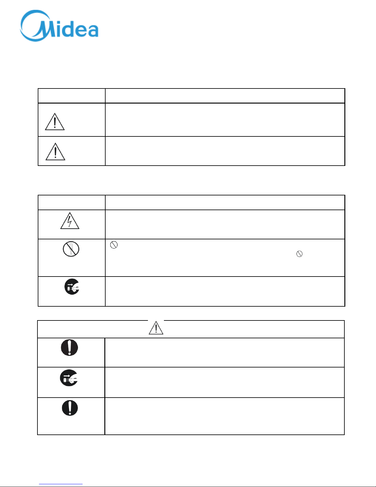
Symbol Meaning
WARNING
Indicates possibility of death or serious injury of a repair technician and a
person nearby through the misconducted work, or of a user by a defect of the
product after the work performed by the technician.
CAUTION
Indicates possibility of injury or physical damages* of a repair technician and a
person nearby through the misconducted work, or of a user by a defect of the
product after the work performed by the technician.
*Means secondary damages of property, furniture, domestic animal and pet.
Symbol Meaning
ELECTRICSHOCK
• indicates a caution (including a warning).
Specific instruction is followed by a graphic or characters in or near • .
Symbol left warns an electric shock.
DONOT
DISASSEMBLE
indicates prohibition (act must not be conducted).
Specific instruction is followed by a graphic or characters in or near
Symbol left warns not to disassemble.
UNPLUG
• indicates forcing (act must be conducted).
Specific instruction is followed by a graphic or characters in or near • .
Symbol left warns to unplug the power cord.
WARNING
OUT OF CHILD
• Advise the customer to keep children out of the work place.
Children may be injured with a tool or a disassembled part.
UNPLUG POWER
• Unplug power cord for the work such as disassembling which is not
unnecessary to power on . Do not hold the plug by a wet hand.
Failing to unplug may cause an electric shock.
USE
REPAIR PARTS
• Use the specified repair parts when repairing the product.
Otherwise, a malfunction or a defect may occur.
Also, a short circuit, ignition or other danger to the customer may occur.
Page 5
2. CAUTIONS FOR SAFETY
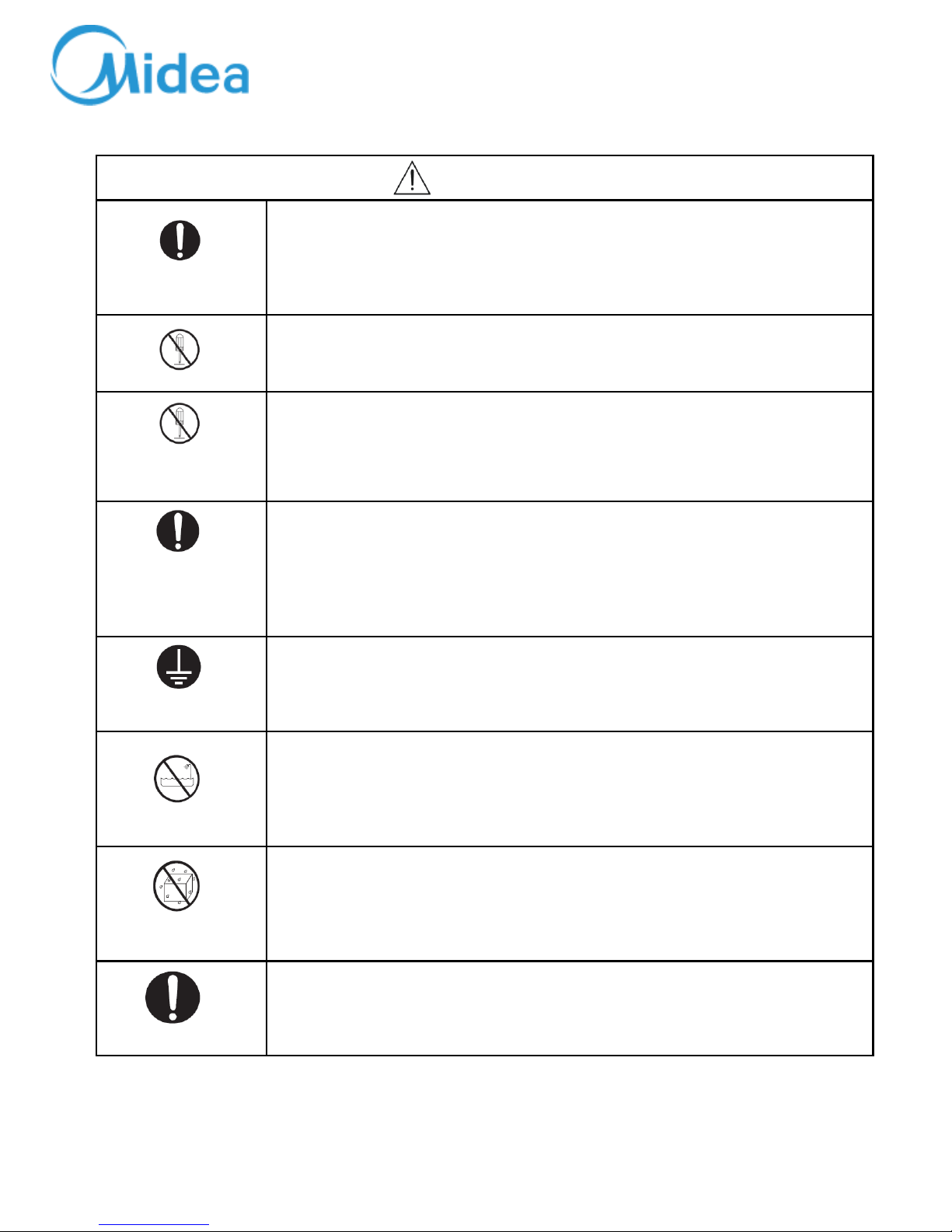
WARNING
CHECK INSULATION
RESISTANCE
• After repair, measure insulation resistance between the charging part
(power cord plug) and the non-charging metallic part (ground) with an
insulation resistance meter (500V). The resistance shall be 10M• or more.
Failing to check the insulation resistance may cause a short circuit, electric
shock or other diseases to the customer.
DO NOT MODIFY
• Do not modify the product.
An electric shock or ignition may occur.
DO NOT
DISASSEMBLE AND
REPAIR
• Only a repair technician can disassemble and repair.
An electric shock, ignition or malfunction may cause injury.
USE EXCLUSIVE
SOCKET
• Use an exclusive 110 VAC/15 A socket for the washing machine.
(AW-B651B/B657B/B761S/B757S)
• Use an exclusive 220 VAC/17 A socket for the washing machine.(Except
above models)
Otherwise, an electric shock or ignition may cause. Sharing the same socket
with other instrument causes heating of a branch socket and result in a fire.
CONNECT
GROUNDING WIRE
• Connect the grounding wire.
Failing to do so may cause an electric shock when a short circuit occurs.
Consult an electric work shop or a sales shop.
DO NOT USE WET
PLACE
• Do not install in a bath room or a place exposed to wind or rain.
An electric shock or a short circuit may cause a fire.
DO NOT SPLASH
WATER
• Do not pour or immerse electrical parts into water or liquid solution.
An electric shock or ignition may occur.
REMOVE DUST
• Wipe off dust adhered to the plug of power cord.
Dust may cause a fire.
2-2
Page 6
2. CAUTIONS FOR SAFETY
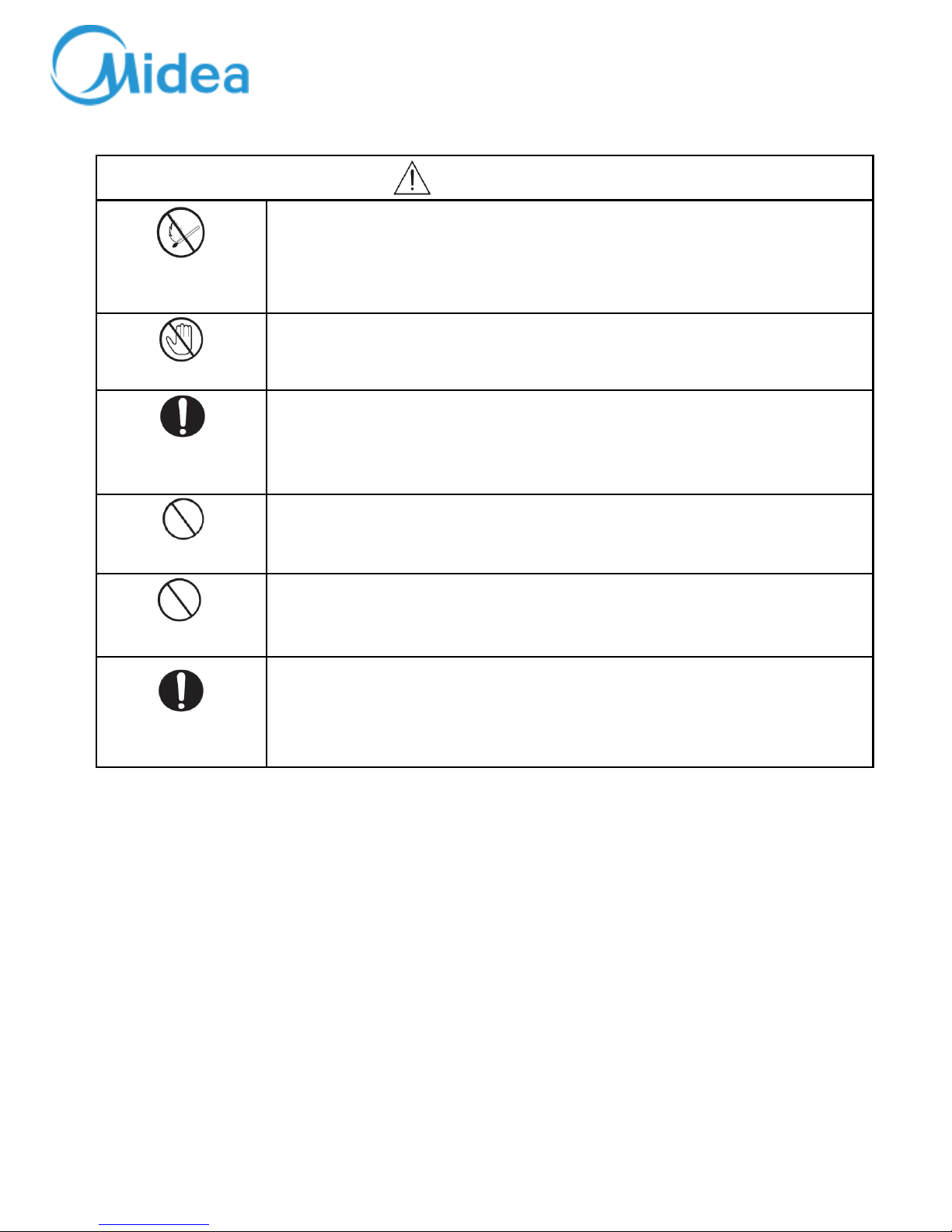
WARNING
AVOID
INFLAMMABLE
• Do not put inflammable into the washing tub.
Do not put cloths stained with kerosene, gasoline, benzene, thinner, alcohol,
etc. lt may cause a fire or explosion.
DO NOT TOUCH
• Do not touch the laundry before the spin basket stops completely.
The laundry entangles your hand causing an injury even if the basket rotates
slowly. Pay special attention to children.
INSTALL
CAREFULLY
• Ask an electric work shop to install the product.
Install the product securely and safely according to the electrical equipment
technical standard and the wiring standard.
Incorrect work causes an electric shock and a fire.
DO NOT PULL
• Do not pull the power cord when unplugging.
Hold the power plug to unplug.
An electric shock or short circuit may cause a fire.
DANGER HAND
• Do not insert your hand under the washing machine during operation.
There is a rotary part under the machine which may cause an injury.
WATER LEAKAGE
• Before starting washing, open the faucet and check water supply hose joint
which shall not be loosened for no water leaks.
The loose screw or hose joint may cause water leakage resulting in an
unexpected damage.
2-3
Page 7
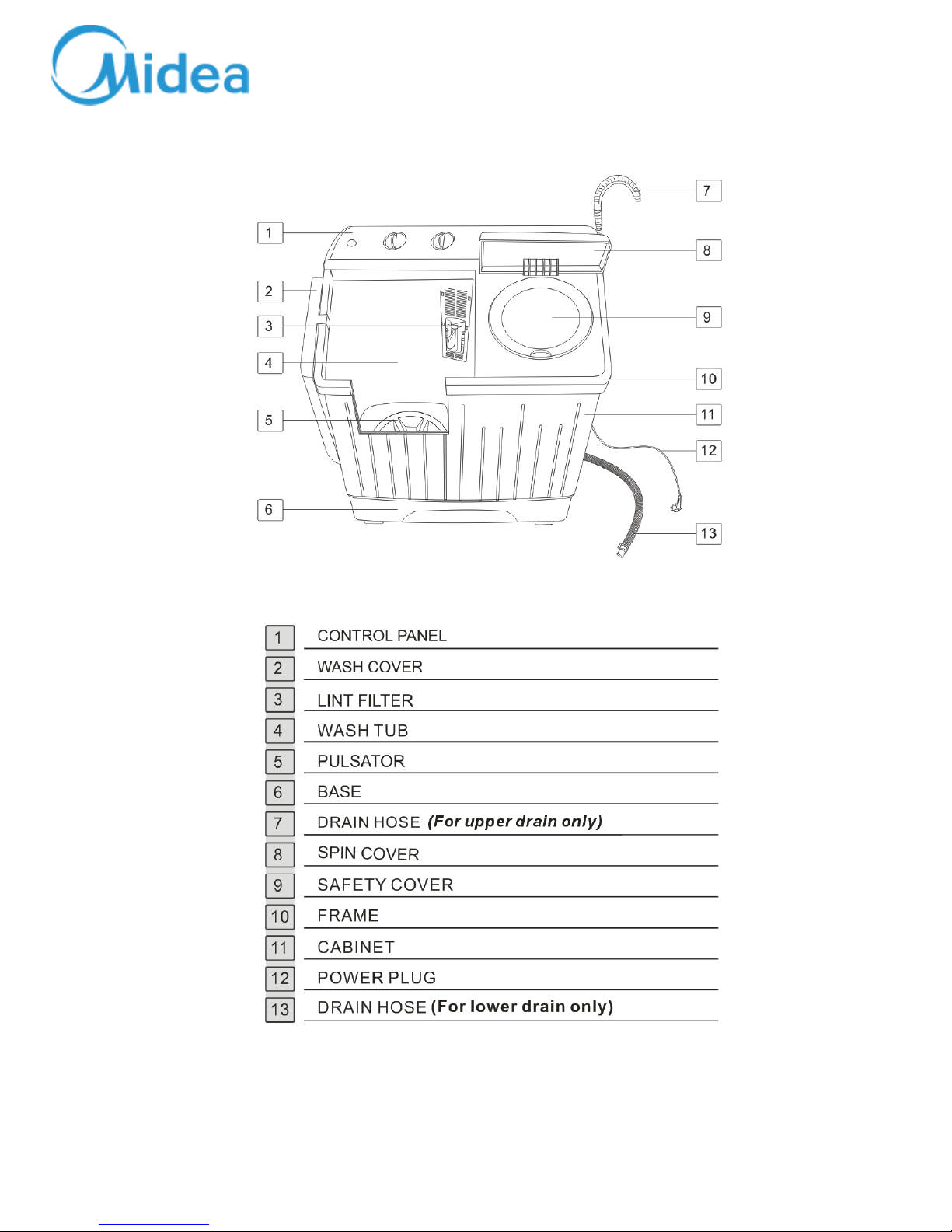
3. DESCRIPTION OF PARTS
3-1
Page 8

3. DESCRIPTION OF PARTS
3-1. Control Panel
3-2
● Water inlet: be used to inject water.
● Wash timer: be used to select required washing time.
● Spin timer: be used to select required spinning time.
● Wash selector: Choose “ Normal”or“ Heavy” according to laundry fabric.
● Drain selector: For upper drain,Choose “Wash”for washing,choose “Rinse”for
rinsing;choose “ Drain” for
draining.For lower drain,Choose “Wash/Rinse”for washing or
rinsing;choose “ Drain” for
draining.
Page 9

3. DESCRIPTION OF PARTS
3-2. Installation
3-2-1. Level Specifications and Wall - Clearance Distances
1) Install the washing machine on a solid and level floor.
2) Place the machine at least 15cm away from the wall.
3) Placement on an inclined, weak or rough floor may
cause abnormal noise or trembling.
3-2-2. Positioning the Drain Hose
1)When there is no threshold, the length of the
drain hose should not exceed 3m.
2)When it is necessary to connect the drain hose
with the drain outlet far away, connect the
extension hose and
applicable parts
available from
dealers or service
centers.
3) Do not install the drain hose where it must exceed
over a threshold of 3cm or more ; do not install
where there is a
threshold
and the hose
must exceed for
more than 2m.
3-3
Page 10

3. DESCRIPTION OF PARTS
3-2-3. Grounding
1) Upon installing grounding,make sure if power socket is out
of power outlet.
2) Grounding should be connected to eithermetal water
supply
pipe or copper grounding pole deeper than 25cm in the damp
ground. (Fig 1)
3) If water pipe is a plastic, no protection is obtained from
a possible electric shock.
4) If the power outlet is available with grounding connection,
grounding in the washingmachine should be firmly connected
to
the connection of the outlet. (Fig 2)
5) You should not connect, the grounding to the gas-pipe
because
it will cause an explosion. (Fig 3)
6) If the grounding is connected to either telecommunication
line
or lightning-arrest line, an extreme hazard is caused therefore,
no connection should bemade to such lines. (Fig 4)
3-4
Page 11

4. DISASSEMBLY AND REASSEMBLY
4-1
ITEM
HOW TO DISASSEMBLE AND ASSEMBLE PICTURE
TIMERWASHING AND
TIMERSPINNING
1. Unscrew the screw of the plusator. (Fig
1)
2. Pull off the knobs by the screwdriver
which with"-"Sharp.
(Fig 2)
3. Pull off the control panel.(Fig 3)
4. Unscrew the screws of the washing
timer & Spin timer(Red circle part)
by the screwdriver which with "+"sharp.
(Fig 4)
(Fig 1)
(Fig 2)
(Fig 3)
(Fig 3)
Page 12

4. DISASSEMBLY AND REASSEMBLY
4-1
ITEM
HOW TO DISASSEMBLE AND ASSEMBLE
PICTURE
BASKETSPINNI
NG
1. Unscrew the screws (Red circle part)
from the back of model by
screwdriver. (Fig 1)
2. Unscrew the screws of the handle by
screwdriver. (Fig2)
3. Unscrew the screw caps by the blade.
(Fig 3)
4. Unscrew the screws of the washing
timer&Spin timer(Red circle part)
by the screwdriver which with "+"sharp.
(Fig 4)
5. Unscrew the screws of backs (Red
circle part) by screwdriver
which with "+"sharp. (Fig 5)
(Fig 1)
(Fig 2)
(Fig 3)
(Fig 4)
Page 13

4. DISASSEMBLY AND REASSEMBLY
4-1
ITEM
HOW TO DISASSEMBLE AND ASSEMBLE
PICTURE
BASKETSPINNI
NG
6. Pull off the breaking belt and drain
belt(Red circle part). (Fig 6)
7. Unscrew the screw at the joint of spin
tub & breaking plate.
(Fig 7)
(Used tool: M8 Box Driver)
8. Open the tub frame. (Fig 8)
9. Pull off the spin tub. (Fig 9)
(Fig 6)
(Fig 7)
(Fig 8)
(Fig 9)
M8 Box driver
Page 14

4. DISASSEMBLY AND REASSEMBLY
4-1
ITEM
HOW TO DISASSEMBLE AND ASSEMBLE
PICTURE
ASSY GEAR
BOX
1. Unscrew the screw of the plusator.
(Fig 1)
2. Take out the plusator's plate, (Fig 2)
3. Pull off the axle of spin tub & screw of
breaking plate, (Fig 3)
Further step check (Fig 6)
4. Unscrew the screws of base. (Fig4)
Take off the base.
5. Unscrew the 4 screws of gear box,
(Fig 5)
Take off the Gear box.
(Fig 1)
(Fig 2)
(Fig 3)
(Fig 4)
(Fig 5)
Page 15

4. DISASSEMBLY AND REASSEMBLY
4-1
ITEM
HOW TO DISASSEMBLE AND ASSEMBLE
PICTURE
MOTORSPINNING
&
MOTORWASHING
1. Unscrew the screw of the plusator.
(Fig 1)
2. Take out the plusator's plate, (Fig 2)
3. Pull off the axle of spin tub & screw of
breaking plate, (Fig 3)
Further step check (Fig 6)
4. Unscrew the screws of base. (Fig4)
Take off the base.
(Fig 1)
(Fig 2)
(Fig 3)
(Fig 4)
Page 16

4. DISASSEMBLY AND REASSEMBLY
4-1
ITEM
HOW TO DISASSEMBLE AND ASSEMBLE
PICTURE
MOTORSPINNING
&
MOTORWASHING
5. Remove the plastic bag on the
connection part,
&detach end connector of motor
wires(Fig 1)
6. Unscrew the 3 screws of Spin
motor(Red circle part). (Fig 2)
7. Unscrew the screws of breaking plate
by M8 tool. (Fig 3)
8. Pulll of the breaking plate by
screwdriver which with "-"
sharp. (Fig 4)
9. Take off the spring of the breaking
plate,and unscrew the
screws of motor(①②③). (Fig 5)
(Fig 1)
(Fig 2)
(Fig 3)
(Fig 4)
(Fig 5)
Page 17

4. DISASSEMBLY AND REASSEMBLY
4-1
ITEM
HOW TO DISASSEMBLE AND ASSEMBLE
PICTURE
MOTORSPINNING
&
MOTORWASHING
FILTER O.F G)
&
MAGIC
FILTER
1. Follow same as disassembling
sequence of the
Motor-Spinning, (1) through (2)
2. Unscrew pulley-Motor nut to
disassembled the pulley(Fig 1)
(Used M8 Spinner / open spinner)
3. Unscrew the 3 screws(①②③) of
washing motor,and take
off the motor. (Fig 2)
G) Disassembly of the FILTER O.F
1. Push the filter front and downward,
and remove it.
( 1 → 2 ) (fig 1)
2. Turn the net direction upside down
and put the dirt in water
and clean it (Fig 2)
3. Install the filter after cleanning. (Fig 3)
(Fig 1)
(Fig 2)
(Fig 1)
(Fig 2)
(Fig 3)
Page 18

4. DISASSEMBLY AND REASSEMBLY
4-1
ITEM
HOW TO DISASSEMBLE AND ASSEMBLE
PICTURE
MOTORSPINNING
&
MOTORWASHING
FILTER O.F G)
&
MAGIC
FILTER
1. Follow same as disassembling
sequence of the
Motor-Spinning, (1) through (2)
2. Unscrew pulley-Motor nut to
disassembled the pulley(Fig 1)
(Used M8 Spinner / open spinner)
3. Unscrew the 3 screws(①②③) of
washing motor,and take
off the motor. (Fig 2)
G) Disassembly of the FILTER O.F
1. Push the filter front and downward,
and remove it.
( 1 → 2 ) (fig 1)
2. Turn the net direction upside down
and put the dirt in water
and clean it (Fig 2)
3. Install the filter after cleanning. (Fig 3)
(Fig 1)
(Fig 2)
(Fig 1)
(Fig 2)
(Fig 3)
Page 19

4. DISASSEMBLY AND REASSEMBLY
4-1
ITEM
HOW TO DISASSEMBLE AND ASSEMBLE
PICTURE
COVER-TOP
FILTER O.F G)
&
MAGIC
FILTER
1. Open the spin lid,install
the tub frame.
(Fig 1)
2. Install the frame and control panel
rightly . (Fig 2)
3. Install the knobs rightly . (Fig 3)
(Fig 1)
(Fig 2)
(Fig 3)
(Fig 4)
(Fig 5)
Page 20

5. SCHEMATIC DIAGRAM
5-1 SINGLE VOLTAGE
5-1
Page 21

6. TROUBLE SHOOTING
6-1
TYPICAL FAILURE POSSIBLE CAUSE REPAIR
Spinning
basket does
not stop
Brake shoe is worn off or broken
Replace brake
shoe
Brake arm does not move
Replace
brake
frame
Brake spring is broken away or
elasticity is insufficient
Replace
brake
spring
Excessive
noise during
spin
Machine
is not level.
Weak floor.
Level the machine.
Install on a
horizontal and
stable floor.
Screw
for fixing motor come
loose.
Fix screw
Clothes break into
the gap
between Tub and basket
Remove clothes
Page 22

7. CHECK POINT AFTER REPAIR
After repairing, be sure to make the following trial operation to see if the washer operates normally.
Check Point Inspection & Judgement
1) Insulation resistance Unplug the cord from the power outlet and turn on all the timers. Then
measure the insulation resistance between the plug (both of 2 pins) and
grounding wire of the machine.
The measured value should be more than1MΩ
In the following case, check sufficiently.
1)Replace the electrical parts with new ones.
2) Used in a moist place.
3)Used more than 5 years.
2) Safety device Check the full stop time of the spin basket.
Braking time should be as follows.
3) Safety designated
parts
Replace with the designated parts in the case the used parts are not proper.
(Refer to '*" marked parts in the parts list)
4) Wiring Check to see if the lead wire is properly connected without looseness or
overtension and taping and setting are firmly performed.
5) Screws and Nuts Check to see if the screws, nuts, etc. are firmly tightened and the screw locks
are
applied.
6) Removal of useless
matter
Check to see if useless matters (Screws, bits of wire, etc.) are left inside the
machine.
7) Leakage of oil and
water
Check to see if oil or water leaks out around bellow-spinning, gear box, motors
and connection of d.v-case.
8) Power-cord Check to see if the cord, the plug, the outlet etc, are not damaged. Do not use
table
Tape with multi-wiring.
9) Level Installation Check to see if the machine installed horizontally.
Load Normal stop time
No load
Rated load
Within 7 sec.
Within 10 sec.
7-1
 Loading...