

Page 1
Air-cooled Package
[Введите текст]
Air-cooled package
Middle Static Pressure Duct unit
High Static Pressure Duct unit
Service Manual 2013
MHB-76CRN1 / MOV-76CN1-C
MHB-96CRN1 / MOV-96CN1-C
MHB-76HRN1 / MOV-76HN1-C
MHB-96HRN1 / MOV-96HN1-C
DM13-01.01.16en
MTA-76CRN1 / MOV-76CN1-C
MTA-96CRN1 / MOV-96CN1-C
MTA-120CRN1 / MOV-120CN1-C
MTA-150CRN1 / 2* MOV-76CN1-C
MTA-76HRN1 / MOV-76HN1-C
MTA-96HRN1 / MOV-96HN1-C
MTA-120HRN1 / MOV-120HN1-C
Page 2

DM13-01.01.16en Air-cooled Package
Service manual 1
Content
Part 1 General Information ............................................ 2
Part 2 Indoor Units ......................................................... 6
Part 3 Outdoor Units .................................................... 44
Part 4 Installation ......................................................... 59
Part 5 Control ............................................................... 92
Page 3

Air-cooled Package DM13-01.01.16en
2 Service manual
Part 1 General Information
1. Model Names of Indoor/Outdoor Units ............................. 3
2. External Appearance .......................................................... 4
3. Nomenclature ...................................................................... 5
Page 4
DM13-01.01.16en Air-cooled Package
Service manual 3
1. Model Names of Indoor/Outdoor Units
1.1 Model Names of Units with Cooling only:
Type
Indoor unit Outdoor unit Capacity
Model
Power
supply
Model
Power
supply
kW Btu/h
Mid-static
pressure duct
type
MTA-76CRN1
220~240V-1
Ph-50Hz
MOV-76CN1-C
380~415V-3
N-50Hz
22 76
MTA-96CRN1 MOV-96CN1-C 28 96
MTA-120CRN1 MOV-120CN1-C
380~400V-3
N-50Hz
35 120
MTA-150CRN1 MOV-76CN1-C *2
380~415V-3
N-50Hz
44 150
High-static
pressure
duct type
MHB-76CRN1 MOV-76CN1-C 22 76
MHB-96CRN1 MOV-96CN1-C 28 96
1.2 Model Names of Units with Cooling and heating:
Type
Indoor unit Outdoor unit Capacity
Model
Power
supply
Model
Power
supply
kW Btu/h
Mid-static
pressure duct
type
MTA-76HRN1
220~240V-1
Ph-50Hz
MOV-76HN1-C
380~415V-3
N-50Hz
22 76
MTA-96HRN1 MOV-96HN1-C 28 96
MTA-120HRN1 MOV-120HN1-C
380~400V-3
N-50Hz
35 120
MTA-150HRN1 MOV-76HN1-C *2
380~415V-3
N-50Hz
44 150
High-static
pressure duct
type
MHB-76HRN1 MOV-76HN1-C 22 76
MHB-96HRN1 MOV-96HN1-C 28 96
Page 5
Air-cooled Package DM13-01.01.16en
4 Service manual
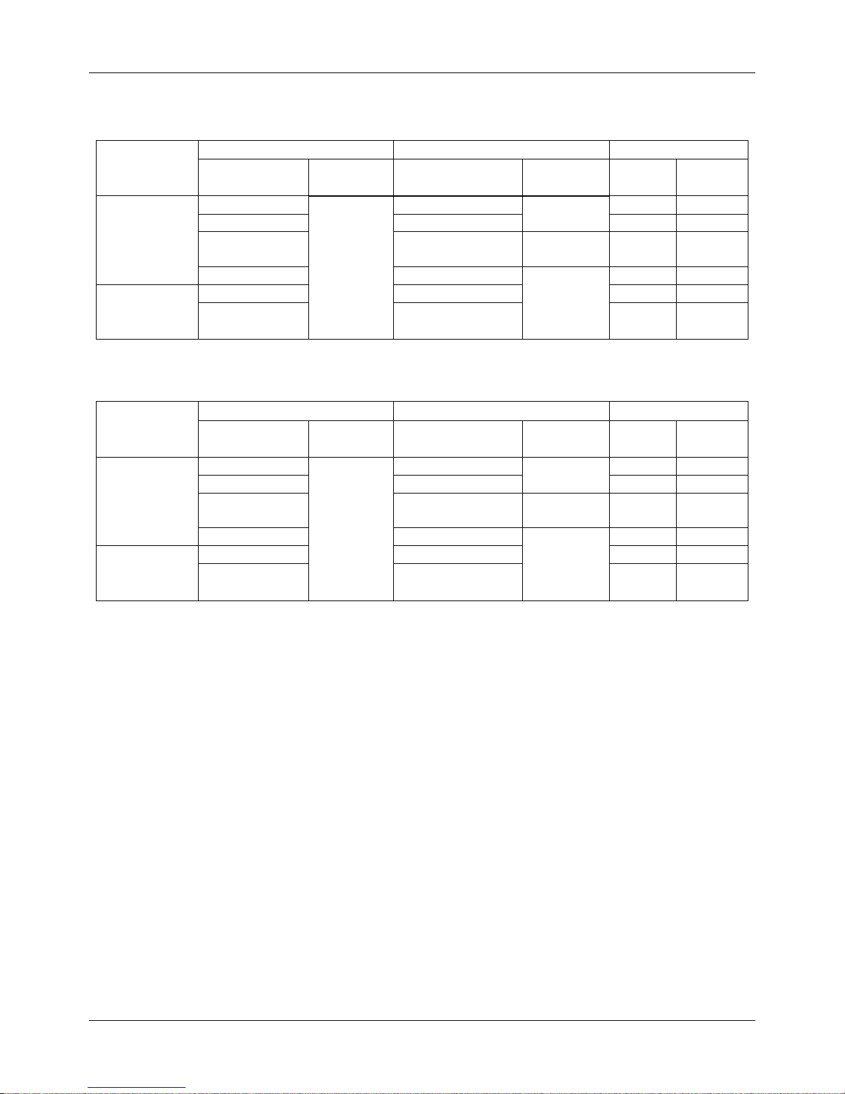
2. External Appearance
2.1 Indoor Units
MTA-76C(H)RN1
MTA-96C(H)RN1
MTA-120CRN1\MTA-120HRN1
MTA-150CRN1
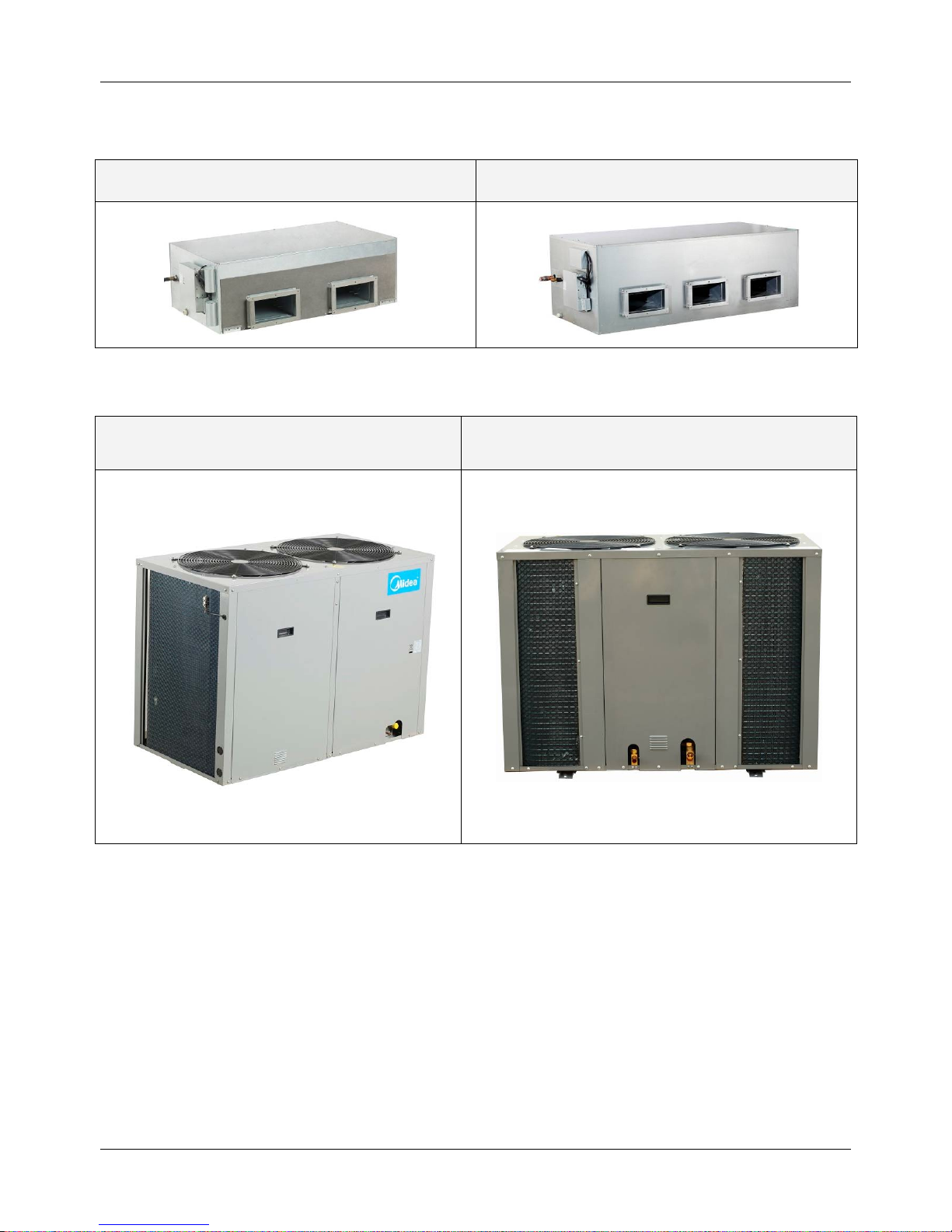
2.2 Outdoor Unit
MOV-76C(H)N1-C
MOV-96C(H)N1-C
MOV-150C(H)N1-C (MOV-76C(H)N1-C*2)
MOV-120C(H)N1-C
Page 6
DM13-01.01.16en Air-cooled Package
Service manual 5
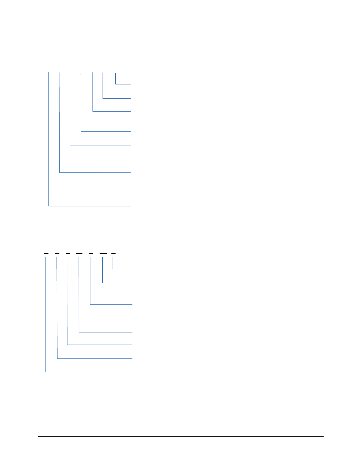
3. Nomenclature
3.1 Indoor unit:
3.2 Outdoor unit:
M T A – 76 C R N1
None:R22;N1:R410a
R:Remote Controller
Function Code: C: Cooling
H: Cooling and Heating
Cooling Capacity (*76 kBtu/h)
Product Series
A: 1
st
time design
B: 2
nd
time design
Indoor Units
T: Duct type
H: High static pressure
Midea
Design times
None:R22;
N1:R410a
Function Code:
C: Cooling Only
H: Heat pump
Cooling Capacity (76 kBtu/h)
Universal Outdoor Unit
Outdoor Unit
Midea
M O V 76 C N1 - C
Page 7

Air-cooled Package DM13-01.01.16en
6 Service manual
Part 2 Indoor Units
1. Features ............................................................................... 7
2. Specifications ..................................................................... 8
3. Dimensions ....................................................................... 11
4. Service Space ................................................................... 12
5. Piping Diagrams ............................................................... 14
6. Wiring Diagrams ............................................................... 14
7.Capacity Table .................................................................... 19
8. Static Pressure .................................................................. 33
9. Electric Characteristics .................................................... 35
10. Sound Levels .................................................................. 36
11. Troubleshooting .............................................................. 37
Page 8
DM13-01.01.16en Air-cooled Package
Service manual 7
1. Features
1. Nested in the ceiling, space-saving and noble.
2. High capacity of cooling/heating, efficient, and energy-saving.
3. The air outlet is laid out according to you desire.
4. Economic and convenient installation
1) Several diffusers branch off from an indoor unit, adjusting the room temperature, which makes many
rooms to be air-conditioned with only one indoor unit.
2) All models feature thin design making them applicable to ceiling pocket that tends to be shallow
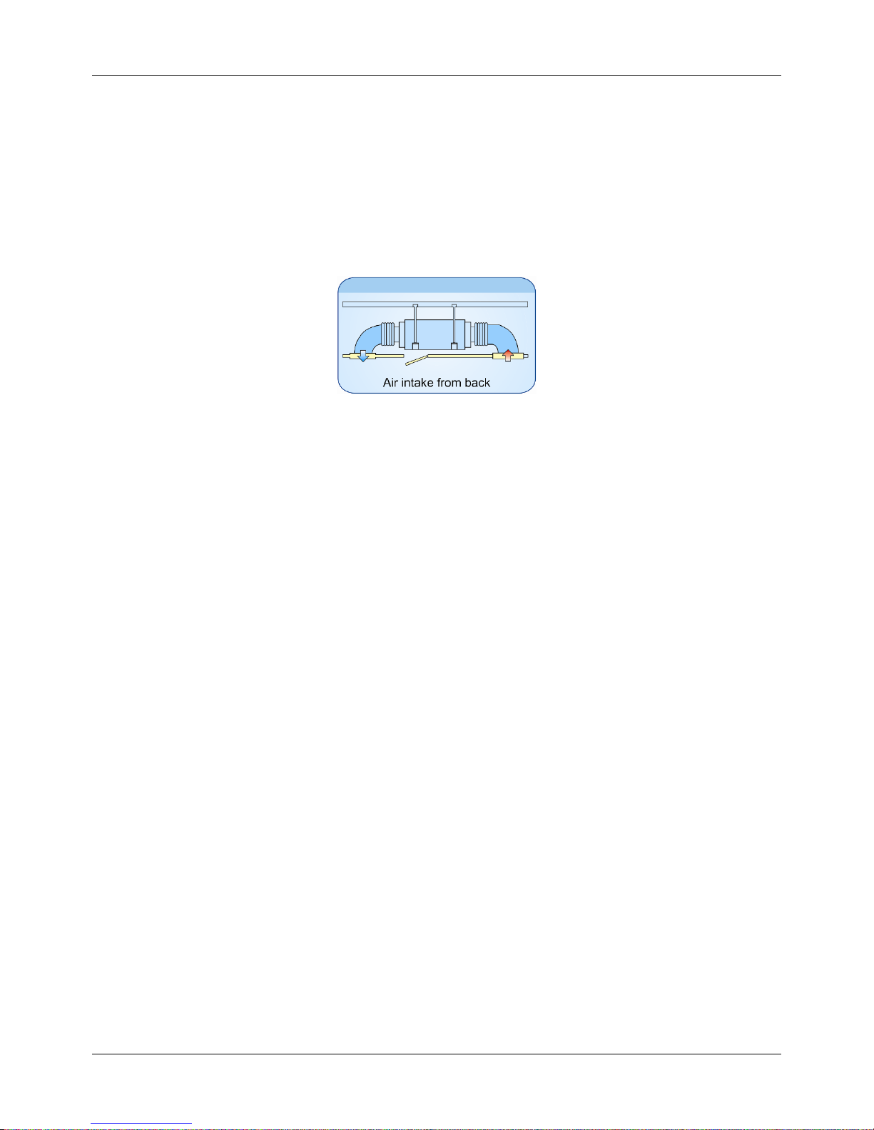
5. Way of air intake and inserting air filter
6. It is suitable be used for office, hospital, commercial place and home, the air conditioner will create the
comfortable and elegance environment for you.
Page 9
Air-cooled Package DM13-01.01.16en
8 Service manual
2. Specifications
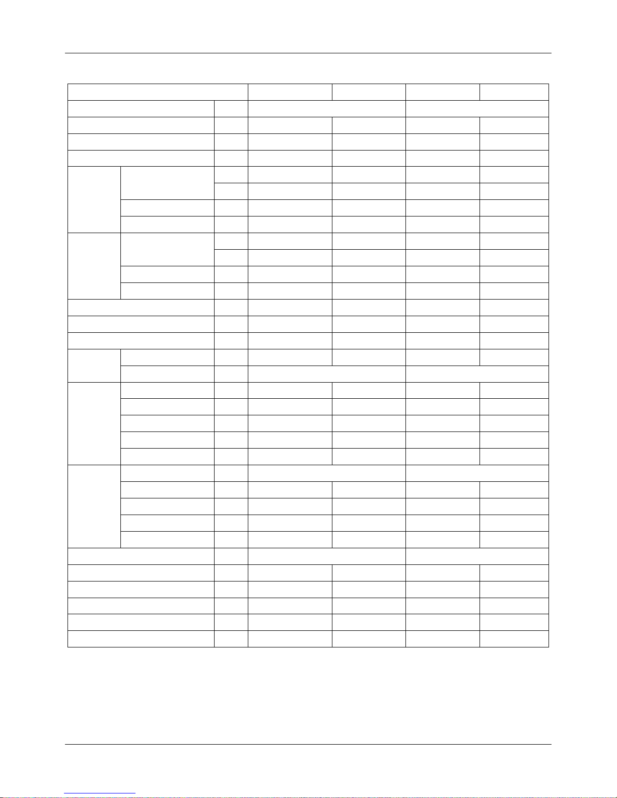
Model MTA-76CRN1 MTA-76HRN1 MTA-96CRN1 MTA-96HRN1
Power supply - 220~240V-1Ph-50Hz 220~240V-1Ph-50Hz
Temp. setting range ℃ ≥17 ≤30 ≥17 ≤30
Rated input power W 11700 11700 14400 14400
Rated current A 19.3 19.3 23.7 23.7
Cooling
Capacity
Btu/h 76000 76000 96000 96000
W
22000 22000 28000 28000
Input W 7500 7500 9600 9600
EER W/W 2.93 2.93 2.92 2.92
Heating
Capacity
Btu/h / 78000 / 105000
W / 25000 / 31000
Input W / 8300 / 10300
COP W/W / 3.01 / 3.01
Indoor air flow m3/h 4250 4250 5100 5100
Indoor standard ESP Pa 100 100 100(98) 100(98)
Indoor noise level dB(A) 54 54 55 55
Refrigerant
Type - R410A R410A R410A R410A
Control - Capillary Capillary
Fan
Type - Centrifugal fan Centrifugal fan Centrifugal fan Centrifugal fan
Dimension mm Φ307 Φ307 Φ307 Φ307
Drive type/ Motor step - Direct/ Single Direct/ Single Direct/ Single Direct/ Single
Motor input* No. W 446*2 446*2 725*2 725*2
Motor speed rpm 877 877 1136 1136
Coil
Type - Copper tube and aluminum fin Copper tube and aluminum fin
Tube size mm Φ9.52 Φ9.52 Φ9.52 Φ9.52
No. of rows - 3 3 4 4
Fin per inch FPI 17 17 17 17
Length* height mm 1200*406.4 1200*406.4 1200*406 1200*406
Controller - Remote controller Remote controller
Drain pipe size mm 41 41 41 41
Dimension (W*H*D) mm 1350*760*450 1350*760*450 1350*760*450 1350*760*450
Packing (W*H*D) mm 1549*476*917 1549*476*917 1549*917*476 1549*917*476
Net/Gross weight kg 105/120 105/120 105/120 105/120
Shipping Qty.(20’/40’/40’HQ) pcs. 30/64/64 30/64/64 30/64/64 30/64/64
Notes:
1. ESP: external static pressure
2. Nominal cooling capacities are based on the following conditions:
Indoor temp: 27°CDB, 19°CWB; Outdoor temp: 35°CDB, 24°CWB; Equivalent refrigerant piping: 7.5m (horizontal).
3. Nominal heating capacities are based on the following conditions:
Indoor temp: 20°CDB, 15°CWB; Outdoor temp: 7°CDB, 6°CWB; Equivalent refrigerant piping: 7.5m (horizontal).
Page 10
DM13-01.01.16en Air-cooled Package
Service manual 9
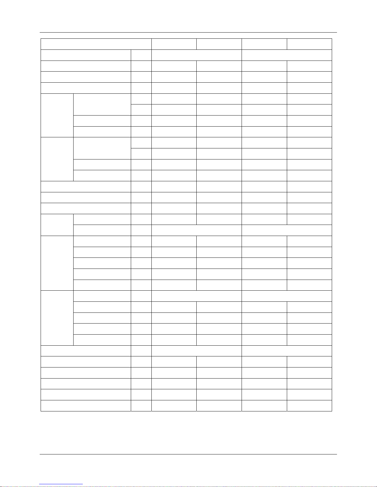
Model MTA-120CRN1 MTA-120HRN1 MTA-150CRN1 MTA-150CRN1
Power supply -
220~240V-1Ph-50Hz
220~240V-1Ph-50Hz
Temp. setting range ℃ ≥17 ≤30 ≥17 ≤30
Rated input power W 17300 17300 21200 21200
Rated current A 28.6 28.6 35 35
Cooling
Capacity
Btu/h
120000 120000
150000 150000
W
35000 35000 44000 44000
Input W 12000 12000 15100 15100
EER W/W 2.92 2.92 2.91 2.91
Heating
Capacity
Btu/h
/ 120000
/ 160000
W
/ 38000
/ 47000
Input W / 12600 / 15700
COP W/W / 3.02 / 3
Indoor air flow m3/h
6375 6375
7650 7650
Indoor standard ESP Pa
150 150
150 150
Indoor noise level dB(A)
56 56
56 56
Refrigerant
Type - R410A R410A R410A R410A
Control - Capillary Capillary
Fan
Type - Centrifugal fan Centrifugal fan Centrifugal fan Centrifugal fan
Dimension mm Φ307 Φ307 Φ307 Φ307
Drive type/ Motor step - Direct/ Single Direct/ Single Direct/ Single Direct/ Single
Motor input * No. W
498*3 498*3
630*3 630*3
Motor speed rpm
860 860
1202 1202
Coil
Type - Copper tube and aluminum fin Copper tube and aluminum fin
Tube size mm Φ7 Φ7 Φ7 Φ7
No. of rows 4 4 4 4
Fin per inch FPI 17 17 17 17
Length* height mm
1602*588 1602*588
1602*588 1602*588
Controller - Remote controller Remote controller
Drain pipe size mm 41 41 41 41
Dimension (W*H*D) mm
1828*858*638 1828*858*638
1828*858*638 1828*858*638
Packing (W*H*D) mm
2095*929*689 2095*929*689
2095*929*689 2095*929*689
Net/Gross weight kg
188/220 188/220
188/200 188/200
Shipping Qty per (20'/40'/40'HD) pcs
19/42/46 19/42/46 19/42/46 19/42/46
Notes:
1. ESP: external static pressure
2. Nominal cooling capacities are based on the following conditions:
Indoor temp: 27°CDB, 19°CWB; Outdoor temp: 35°CDB, 24°CWB; Equivalent refrigerant piping: 7.5m (horizontal).
3. Nominal heating capacities are based on the following conditions:
Indoor temp: 20°CDB, 15°CWB; Outdoor temp: 7°CDB, 6°CWB; Equivalent refrigerant piping: 7.5m (horizontal).
Page 11
Air-cooled Package DM13-01.01.16en
10 Service manual
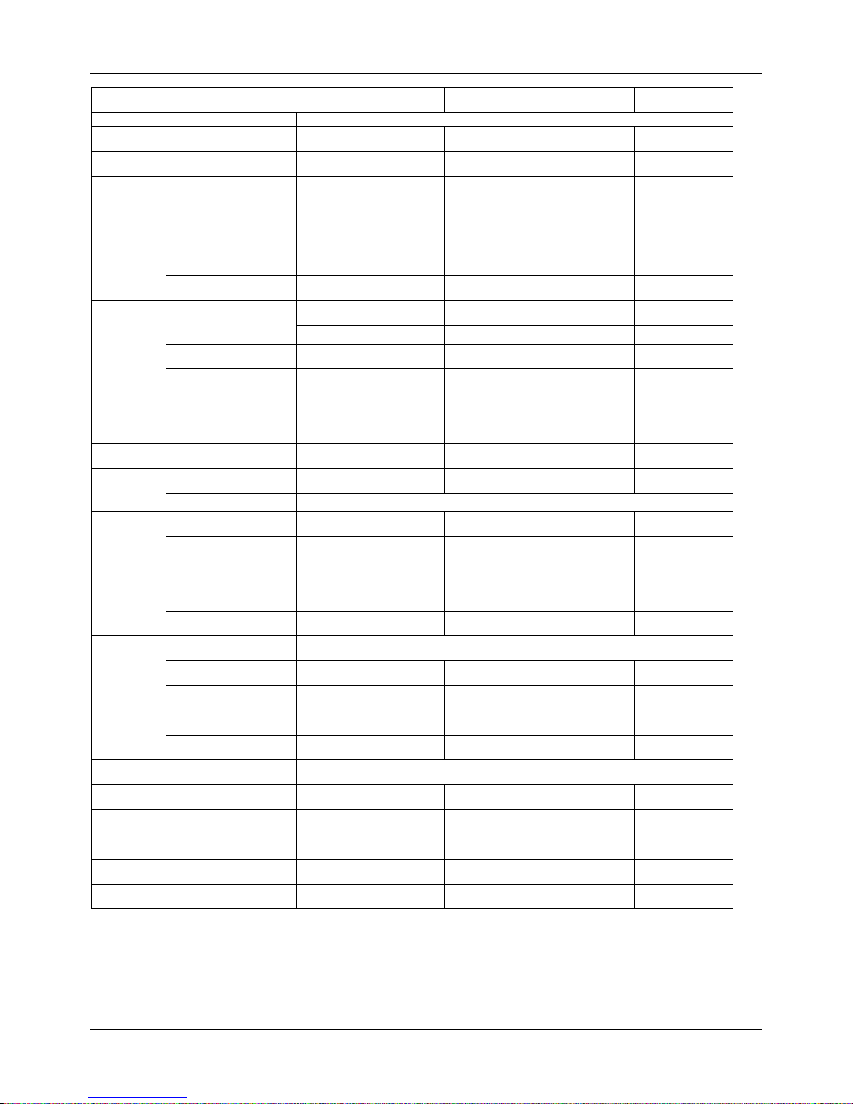
Model MHB-76CRN1 MHB-76HRN1 MHB-96CRN1 MHB-96HRN1
Power supply - 220~240V-1Ph-50Hz 220~240V-1Ph-50Hz
Temp. setting range ℃ ≥17 ≤30 ≥17 ≤30
Rated input power W 11700 11700 14400 14400
Rated current A 19.3 19.3 23.7 23.7
Cooling
Capacity
Btu/h 76000 76000 96000 96000
W 22000 22000 28000 28000
Input power W 7500 7500 9600 9600
EER W/W 2.93 2.93 2.92 2.92
Heating
Capacity
Btu/h / 78000 / 95500
w / 25000 / 31000
Input power W / 8300 / 10300
COP W/W / 3.01 / 3.01
Indoor air flow m3/h 4250 4250 5100 5100
Indoor standard ESP Pa 196 196 196 196
Indoor noise level dB(A) 58 58 60 60
Refrigerant
Type - R410A R410A R410A R410A
Control - Capillary Capillary
Fan
Type - Centrifugal fan Centrifugal fan Centrifugal fan Centrifugal fan
Dimension mm Φ307 Φ307 Φ307 Φ307
Drive type/ Motor step - Direct/ Single Direct/ Single Direct/ Single Direct/ Single
Motor input* No. W 663*2 663*2 788*2 788*2
Motor speed rpm 1022/871/758 1022/871/758 1135/983/845 1135/983/845
Coil
Type - Copper tube and aluminum fin Copper tube and aluminum fin
Tube size mm Φ9.52 Φ9.52 Φ9.52 Φ9.52
No. of rows - 3 3 4 4
Fin per inch FPI 17 17 17 17
Length*Height mm 1200*406.4 1200*406.4 1200*406 1200*406
Controller - Remote controller Remote controller
Drain pipe size mm 41 41 41 41
Dimension (W*H*D) mm 1350*760*450 1350*760*450 1350*760*450 1350*760*450
Packing (W*H*D) mm 1549*476*917 1549*476*917 1549*917*476 1549*917*476
Net/Gross weight kg 105/120 105/120 105/120 105/120
Shipping Qty per (20'/40'/40'HD) pcs 30/64/64 30/64/64 30/64/64 30/64/64
Notes:
1. ESP: external static pressure
2. Nominal cooling capacities are based on the following conditions:
Indoor temp: 27°CDB, 19°CWB; Outdoor temp: 35°CDB, 24°CWB; Equivalent refrigerant piping: 7.5m (horizontal).
3. Nominal heating capacities are based on the following conditions:
Indoor temp: 20°CDB, 15°CWB; Outdoor temp: 7°CDB, 6°CWB; Equivalent refrigerant piping: 7.5m (horizontal).
Page 12
DM13-01.01.16en Air-cooled Package
Service manual 11
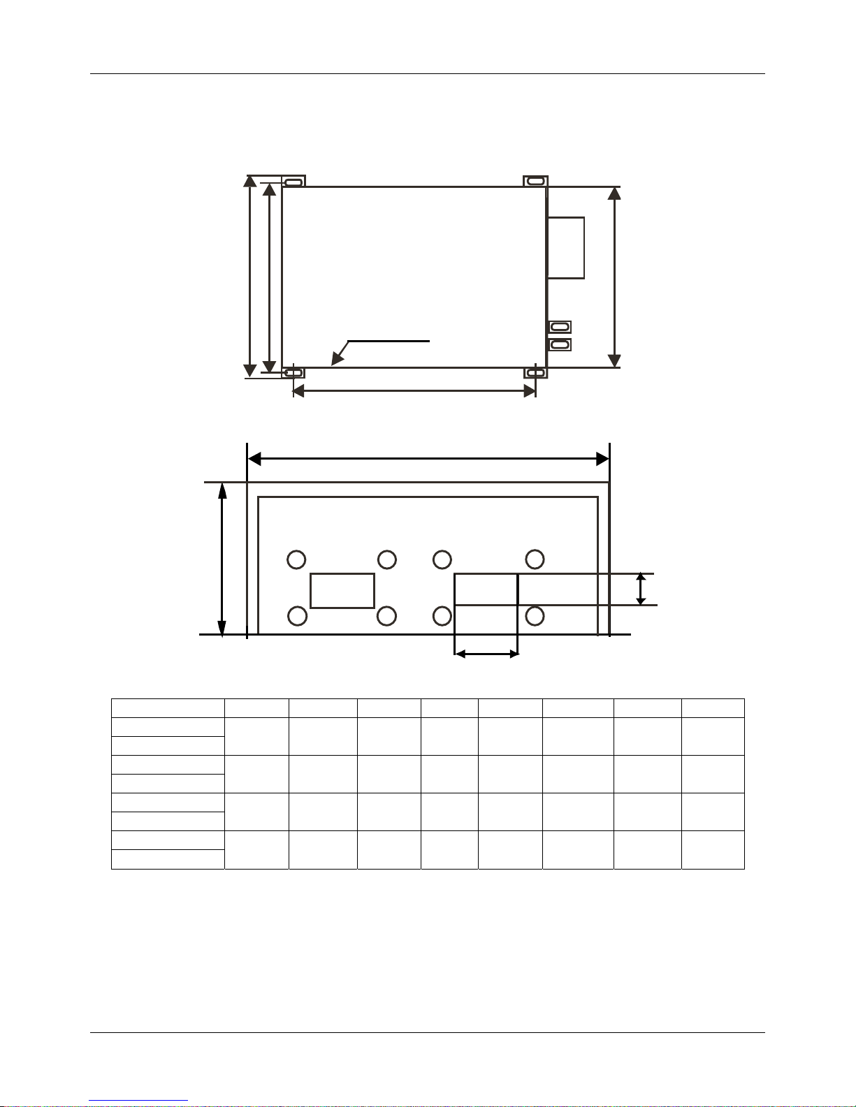
3. Dimensions
3.1 Duct type units with two air outlets:
Air inlet side
C
A
B
D
W
F
H
E
Model A (mm) B (mm) C(mm) E(mm) F(mm) W (mm) H (mm) D (mm)
MTA-76CRN1
840 800 1180 300 165 1350 450 760
MTA-76HRN1
MTA-96CRN1
840 800 1180 300 165 1350 450 760
MTA-96HRN1
MHB-76CRN1
840 800 1180 300 165 1350 450 760
MHB-76HRN1
MHB-96CRN1
840 800 1180 300 165 1350 450 760
MTA-96HRN1
Page 13
Air-cooled Package DM13-01.01.16en
12 Service manual
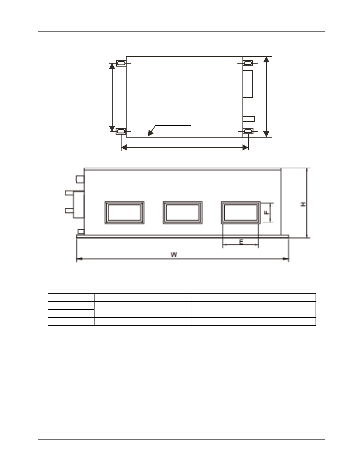
3.2 Duct type units with three air outlets:
Air inlet side
C
B
D
Model B (mm) C(mm) E(mm) F(mm) W (mm) H (mm) D (mm)
MTA-120CRN1
794.5 1895 330 180 1970 668 860
MTA-120HRN1
MTA-150CRN1 794.5 1895 330 180 1970 668 860
Page 14
DM13-01.01.16en Air-cooled Package
Service manual 13
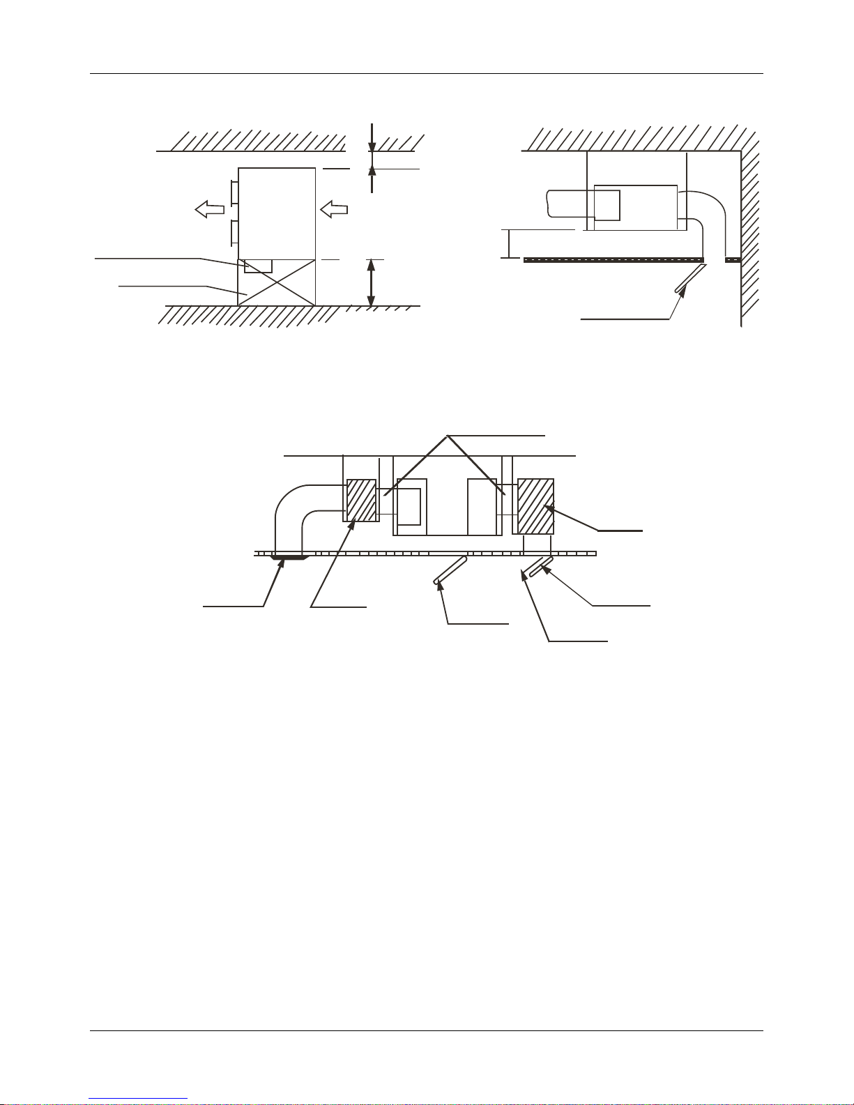
4. Service Space
Electric control box
Inspection hole
≥
6
0
0
m
m
≥
5
0
0
m
m
Inspection hole
H
Top view Side view
Inspection
Canvas adapter
Muffle
ir outlet
Air inlet
Air filter
hole
Muffle
Air duct system
Page 15
Air-cooled Package DM13-01.01.16en
14 Service manual
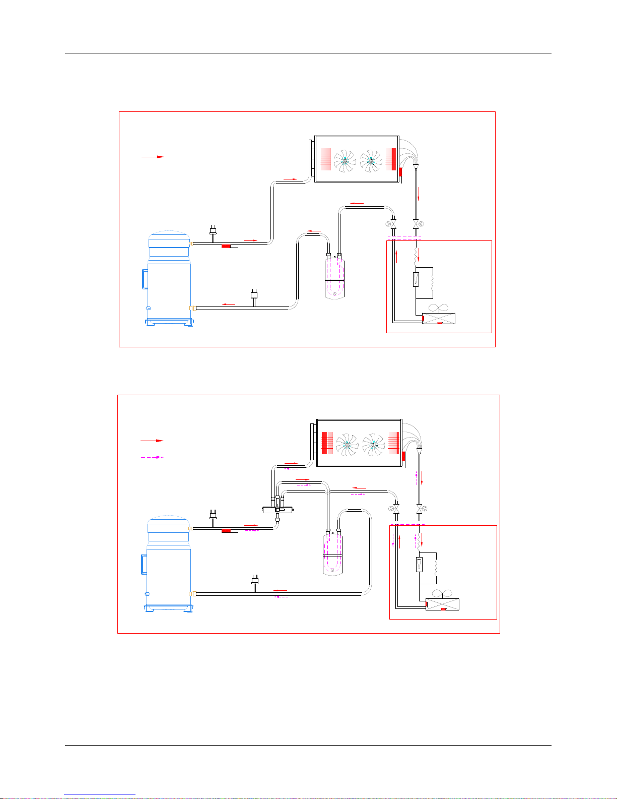
5. Refrigerant cycle diagram
5.1 Cooling only: MTA-76CRN1, MTA-96CRN1, MTA-120CR N1, MTA-150CR N1
MHB-76CRN1, MHB-96CRN1
Discharge temp. sensor
HP Switch
Compressor
Liquid-gas seperator
Outdoor heat-exchanger
Stop valve
Stop valve
Indoor unit
Check valve
LP Switch
T4
T2
T3
Cooling
Indoor
heat-exchanger
5.2 Cooling and heating: MTA-76HRN1, MTA-96HRN1, MTA-120HRN1
MHB-76HRN1, MHB-96HRN1
Discharge temp. sensor
HP Switch
Compressor
4-way valve
Liquid-gas seperator
Outdoor heat-exchanger
Stop valve
Stop valve
Indoor unit
Check valve
LP Switch
T4
T2
T3
Heating
Cooling
Indoor
heat-exchanger
Page 16
DM13-01.01.16en Air-cooled Package
Service manual 15
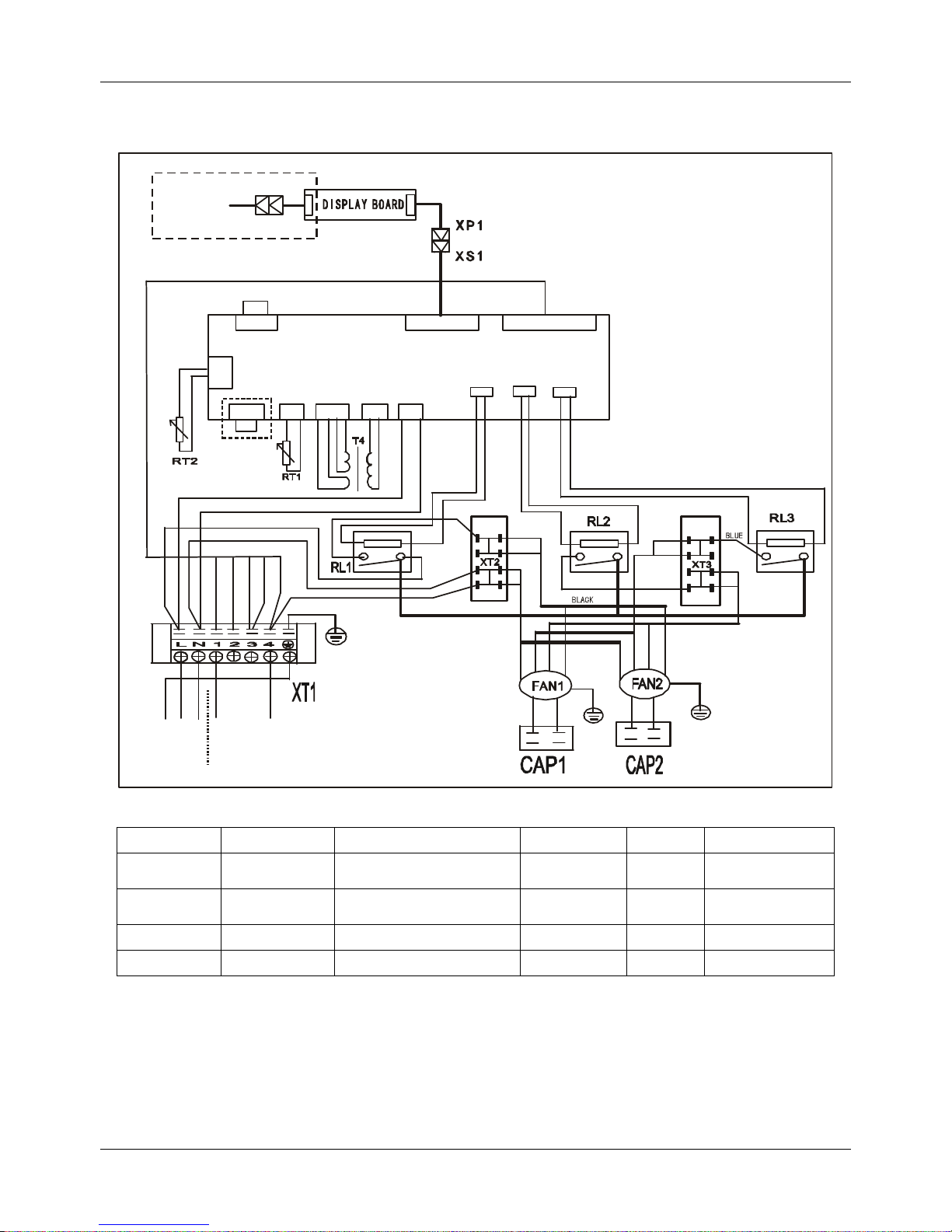
6. Wiring Diagrams
6.1 MTA-76CRN1, MTA-96CRN1, MHB-76CRN1, MHB-96CRN1
INDOOR PO WER
Y
E
L
L
O
W
G
R
E
E
N
B
R
O
W
N
B
L
U
E
R
E
D
B
L
U
E
R
E
D
W
H
I
T
E
RED RED
WHITE
SLOW
HIGH
LOW
BLUE
TO OUTDOO R
B
L
A
C
K
Y
E
L
L
O
W
R
E
D
WHITE
B
L
U
E
Y/G
B
L
A
C
K
R
E
D
WHITE
B
L
U
E
Y/G
MAIN CONTROL BOARD
WHITE
(GRAY)
WHITE
(GRAY)
CN20 CN7 CN3 CN2 CN1
CN8
CN11 CN10 CN15
TO WI RE
CONTROLLER
RL1 RL2 RL3
BLUE
RED
B
R
O
W
N
B
R
O
W
N
B
R
O
W
N
B
R
O
W
N
B
R
O
W
N
B
R
O
W
N
Y
E
L
L
O
W
BLACK
B
L
A
C
K
R
E
D
B
L
U
E
Y
E
L
L
O
W
Y/G
RED
WHITE
B
L
U
E
B
L
U
E
N-LINE
R
E
D
BLACK
Item Name Item Name Item Name
CAP1-CAP2 Indoor fan cap
CN1-3,CN7,CN8, CN10,
CN11,CN15,CN20
PCB sockets T4 Transformer
FAN1-FAN2 Indoor fan RT1
Room temp.
sensor
RT2
Pipe temp.
sensor
XP1 Connector XS1 Connector XT1 7-way terminal
XT2,XT3 Mid terminal RL1,RL2,RL3 Relay - -
Page 17

Air-cooled Package DM13-01.01.16en
16 Service manual
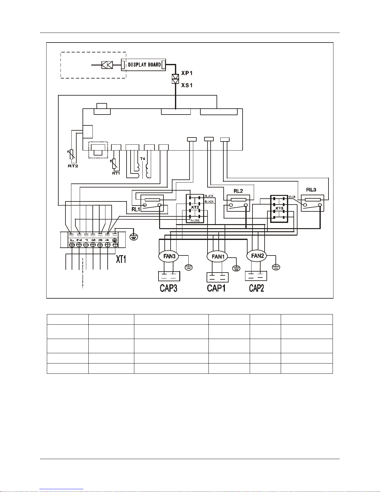
MTA-120CRN1, MTA-150CRN1
INDOOR POWER
B
L
A
C
K
Y
E
L
L
O
W
Y
E
L
L
O
W
G
R
E
E
N
B
R
O
W
N
B
L
U
E
R
E
D
B
L
U
E
R
E
D
R
E
D
WHITE
RED RED
WHITE
WHITE
(GRAY)
WHITE
SLOW
HIGH
LOW
BLUE
BLUE
RED
TO OUTDOOR
Y/G
B
L
A
C
K
Y
E
L
L
O
W
R
E
D
WHITE
B
L
U
E
Y/G
B
L
A
C
K
R
E
D
WHITE
B
L
U
E
Y/G
MAIN CONTROL BOARD
WHITE
(GRAY)
WHITE
(GRAY)
CN20 CN 7 CN3 CN2 CN1
CN8
CN11 CN10 CN15
TO WIRE
CONTROLLER
RL1 RL2 RL3
BLUE
RED
B
R
O
W
N
B
R
O
W
N
B
R
O
W
N
B
R
O
W
N
B
R
O
W
N
B
R
O
W
N
B
L
U
E
Y
E
L
L
O
W
B
L
A
C
K
B
L
A
C
K
R
E
D
R
E
D
B
L
U
E
B
L
U
E
Y
E
L
L
O
W
Y
E
L
L
O
W
Y/G
WHITE
R
E
D
BLACK
Item Name Item Name Item Name
CAP1-CAP3 Indoor fan cap
CN1-3,CN7,CN8,
CN10,CN11,CN15,CN20
PCB sockets T4 Transformer
FAN1-FAN3 Indoor fan RT1
Room temp.
sensor
RT2
Pipe temp.
sensor
XP1 Connector XS1 Connector XT1 7-way terminal
XT2,XT3 Mid terminal RL1,RL2,RL3 Relay - -
Page 18

DM13-01.01.16en Air-cooled Package
Service manual 17
6.2 MTA-76HRN1, MTA-96HRN1, MHB-76HRN1, MHB-96HRN1
INDOOR POWER
Y
E
L
L
O
W
G
R
E
E
N
B
R
O
W
N
B
L
U
E
R
E
D
B
L
U
E
R
E
D
WHITE
RED
RED
WHITE
SLOW
HIGH
LOW
R
E
D
TO OUTDOOR
B
L
A
C
K
Y
E
L
L
O
W
R
E
D
WHITE
B
L
U
E
Y/G
B
L
A
C
K
R
E
D
WHITE
B
L
U
E
Y/G
MAIN CONTROL BOAR D
WHITE
(GRAY)
WHITE
(GRAY)
CN20 CN7 CN3 CN2 CN1
CN8
CN11 CN10 CN15
TO WIRE
CONTROLLER
RL1 RL2 RL3
BLUE
RED
B
R
O
W
N
B
R
O
W
N
B
R
O
W
N
B
R
O
W
N
B
R
O
W
N
B
R
O
W
N
Y
E
L
L
O
W
B
L
A
C
K
R
E
D
B
L
U
E
Y
E
L
L
O
W
Y/G
WHITE
RED
BLUE
B
L
U
E
B
L
U
E
N-LINE
BLACK
BLACK
YELLOW
BLACK
Item Name Item Name Item Name
CAP1-CAP2 Indoor fan cap
CN1-3,CN7,CN8,
CN10,CN11,CN15,CN20
PCB sockets T4 Transformer
FAN1-FAN2 Indoor fan RT1
Room temp.
sensor
RT2
Pipe temp.
sensor
XP1 Connector XS1 Connector XT1 7-way terminal
XT2,XT3 Mid terminal RL1,RL2,RL3 Relay - -
Page 19
Air-cooled Package DM13-01.01.16en
18 Service manual
MTA-120HRN1
INDOOR POWER
B
L
A
C
K
Y
E
L
L
O
W
Y
E
L
L
O
W
G
R
E
E
N
B
R
O
W
N
B
L
U
E
R
E
D
B
L
U
E
R
E
D
R
E
D
WHITE
RED RED
WHITE
WHITE
(GRAY)
WHITE
SLOW
HIGH
LOW
BLUE
BLUE
RED
TO OUTDOO R
Y/G
B
L
A
C
K
Y
E
L
L
O
W
R
E
D
WHITE
B
L
U
E
Y/G
B
L
A
C
K
R
E
D
WHITE
B
L
U
E
Y/G
MAIN CONT ROL BOARD
WHITE
(GRAY)
WHITE
(GRAY)
CN20 CN7 CN3 CN2 CN1
CN8
CN11 CN10 CN15
TO WIRE
CONTROLLER
RL1 RL2 RL3
BLUE
RED
B
R
O
W
N
B
R
O
W
N
B
R
O
W
N
B
R
O
W
N
B
R
O
W
N
B
R
O
W
N
B
L
U
E
Y
E
L
L
O
W
B
L
A
C
K
B
L
A
C
K
R
E
D
R
E
D
B
L
U
E
B
L
U
E
Y
E
L
L
O
W
Y
E
L
L
O
W
Y/G
WHITE
R
E
D
BLACK
Item Name Item Name Item Name
CAP1-CAP3 Indoor fan cap
CN1-3,CN7,CN8,
CN10,CN11,CN15,CN20
PCB sockets T4 Transformer
FAN1-FAN3 Indoor fan RT1
Room temp.
sensor
RT2
Pipe temp.
sensor
XP1 Connector XS1 Connector XT1 7-way terminal
XT2,XT3 Mid terminal RL1,RL2,RL3 Relay - -
Page 20
Air-cooled Package DM13-01.01.16en
19 Service manual
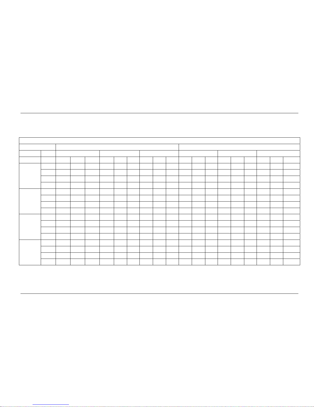
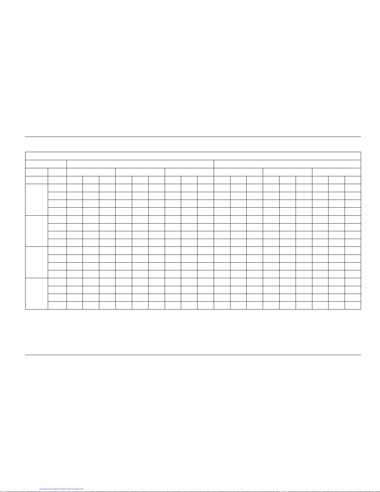
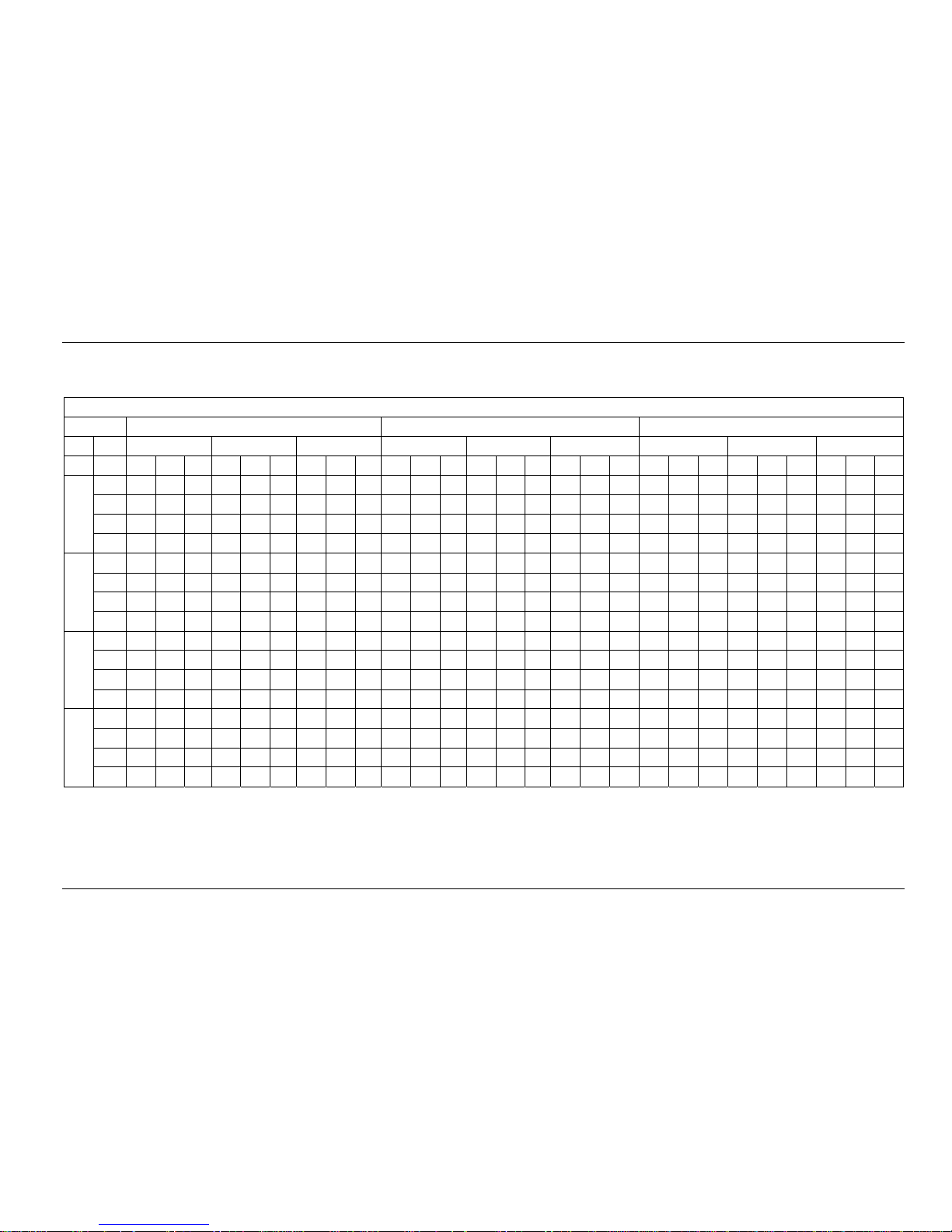
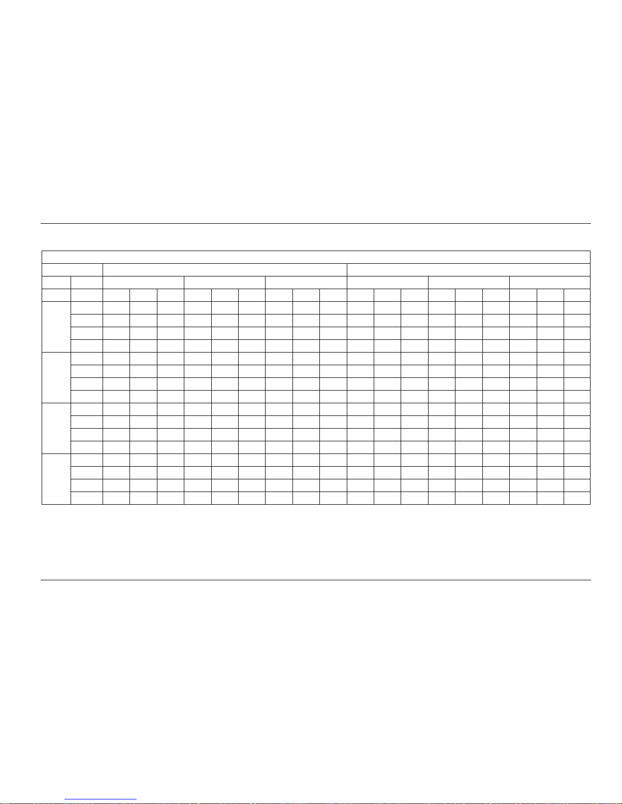
7. Capacity Table
7.1 Cooling:
7.1.1 MTA-76CRN1
Gross Cooling Capacity(kW)
Outdoor DB(°C) 29.40 35.00
Indoor WB (°C) 16.10 19.40 22.80 16.10 19.40 22.80
CFM DB(°C) TGC SHC PI TGC SHC PI TGC SHC PI TGC SHC PI TGC SHC PI TGC SHC PI
2000
23.9
19.5 15.2 6.56 21.9 12.4 6.76 23.3 5.4 6.89 18.7 15.3 6.99 20.8 11 .7 7.22 22.0 5.1 7.36
26.7 20.2 17.4 6.58 22.4 14.5 6.78 23.8 10.3 6.91 19.1 17.4 7.01 21.2 13.7 7.24 22.5 9.7 7.38
29.4 20.9 19.0 6.60 22.8 18.7 6.80 24.3 14.4 6.93 19.5 18.7 7.03 21.6 17.7 7.26 22.9 13.6 7.40
32.2 21.6 21.2 6.61 23.3 21.2 6.81 24.7 18.2 6.94 19.9 19.5 7.05 22.0 20.0 7.28 23.4 17.2 7.42
2300
23.9
20.6 16.5 6.76 22.5 13.0 6.96 23.9 5.6 7.09 19.7 16.6 7.19 21.4 12.4 7.42 22.6 5.3 7.56
26.7 21.3 18.5 6.78 23.0 16.3 6.98 24.4 10.7 7.11 20.1 18.6 7.21 21.8 15.5 7.44 23.1 10.1 7.58
29.4 22.0 20.4 6.80 23.5 19.7 7.00 24.9 15.2 7.13 20.5 20.1 7.23 22.2 18.7 7.46 23.6 14.4 7.60
32.2 22.8 21.7 6.81 23.9 22.2 7.01 25.4 18.9 7.15 20.9 20.9 7.25 22.7 21.0 7.47 24.0 17.9 7.62
2500
23.9
21.1 18.3 7.00 23.0 14.4 7.33 24.4 6.3 7.33 20.2 18.5 7.43 21.9 13.7 7.48 23.1 6.0 7.80
26.7 21.8 20.8 7.02 23.5 18.1 7.22 24.9 11 .9 7.35 20.6 20.6 7.45 22.0 17.2 7.50 23.6 11. 3 7.82
29.4 22.6 21.9 7.04 24.0 22.0 7.24 25.4 16.8 7.37 21.0 21.0 7.47 22.7 20.9 7.70 24.1 15.9 7.84
32.2 23.4 22.9 7.06 24.4 22.2 7.26 25.9 21.1 7.39 21.4 21.4 7.49 23.2 21.1 7.72 24.6 20.0 7.86
2800
23.9
21.5 19.1 7.31 23.5 14.1 7.51 24.9 6.1 7.64 21.0 18.6 7.74 22.4 13.4 7.97 23.6 5.8 8.11
26.7 22.3 21.4 7.33 24.0 17.6 7.53 25.4 11 .5 7.66 21.4 20.6 7.76 22.8 16.8 7.99 24.1 11. 0 8.13
29.4 23.1 22.4 7.35 24.5 21.3 7.55 25.9 16.4 7.68 21.8 21.8 7.78 23.3 20.2 8.01 24.6 15.6 8.15
32.2 23.9 23.4 7.37 25.0 24.0 7.57 26.4 20.5 7.70 22.3 22.3 7.80 23.7 22.8 8.03 25.1 19.4 8.17
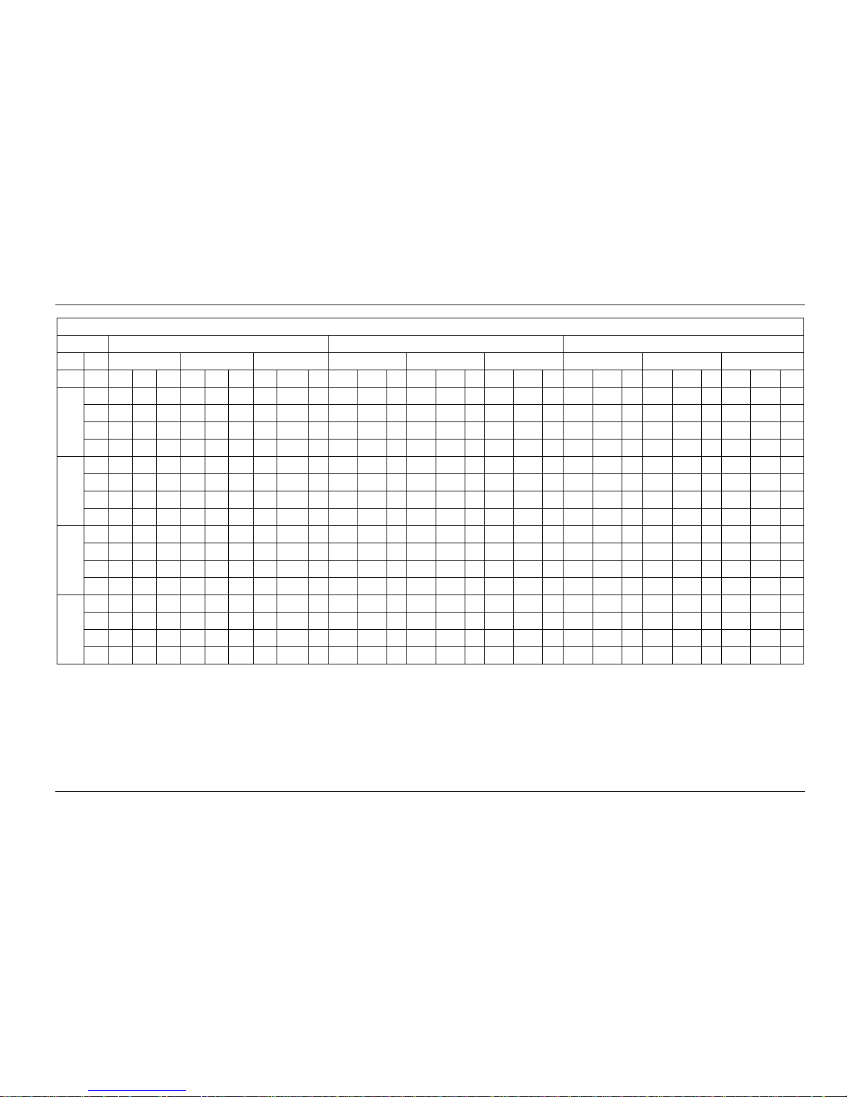
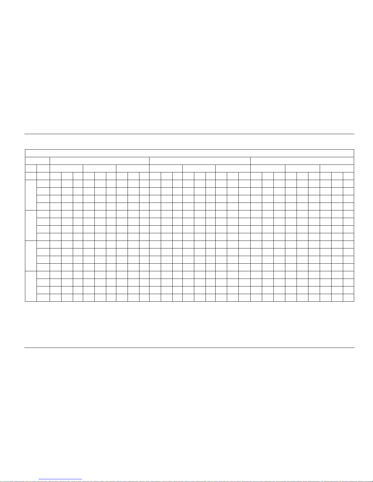
Page 21
Air-cooled Package DM13-01.01.16en
20 Service manual
Gross Cooling Capacity (kW)
Outdoor DB(°C)
40.60 46.10 51.70
Indoor WB(°C)
16.10 19.40 22.80 16.10 19.40 22.80 16.10 19.40
22.80
CFM DB(°C)
TGC SHC PI TGC SHC PI TGC SHC PI TGC SHC PI TGC SHC PI TGC SHC PI TGC SHC PI TGC SHC PI TGC SHC PI
2000
23.9 17.3 14.2 7.94 18.9 10.7 8.18 20.1 4.6 8.33 15.8 13.0 8.13 17.3 9.8 8.39 18.5 4.3 8.64 15.5 12.7 8.51 16.8 9.5 8.87 17.9 4.1 9.12
26.7 17.6 16.0 7.96 19.2 12.5 8.20 20.5 8.8 8.35 16.1 14.7 8.15 17.6 11.4 8.41 18.8 8.1 8.66 15.8 14.4 8.53 17.1 11.1 8.89 18.2 7.9 9.14
29.4 18.0 17.3 7.98 19.6 16.1 8.22 20.9 12.5 8.37 16.5 15.8 8.17 18.0 14.7 8.43 19.2 11.4 8.68 16.2 15.5 8.55 17.5 14.3 8.91 18.6 11.1 9.16
32.2 18.3 18.0 8.00 20.0 18.2 8.24 21.4 15.7 8.39 16.8 16.5 8.19 18.3 16.7 8.45 19.6 14.4 8.70 16.5 16.2 8.57 17.8 16.2 8.93 19.0 14.0 9.19
2300
23.9 17.9 15.0 8.14 19.5 11.2 8.38 20.7 4.9 8.53 16.4 13.8 8.33 17.9 10.3 8.59 19.1 4.5 8.84 16.1 13.6 8.71 17.4 10.1 9.07 18.5 4.4 9.32
26.7 18.3 16.9 8.16 19.9 14.1 8.40 21.2 9.3 8.55 16.8 15.5 8.35 18.3 12.9 8.61 19.5 8.5 8.86 16.5 15.2 8.73 17.8 12.6 9.09 18.9 8.3 9.34
29.4 18.6 18.3 8.18 20.2 17.0 8.42 21.6 13.2 8.57 17.1 16.8 8.37 18.6 15.6 8.63 19.8 12.1 8.88 16.8 16.5 8.75 18.1 15.2 9.11 19.2 11.7 9.36
32.2 19.0 19.0 8.20 20.7 19.1 8.44 22.0 16.4 8.59 17.4 17.4 8.39 19.0 17.6 8.65 20.2 15.1 8.90 17.1 17.1 8.77 18.5 17.1 9.14 19.6 14.6 9.39
2500
23.9 18.4 16.9 7.84 20.0 12.5 8.23 21.2 5.5 8.23 16.9 15.5 8.57 18.4 11.5 8.83 19.6 5.1 9.08 16.6 15.3 8.95 17.9 11.2 9.31 19.0 4.9 9.56
26.7 18.8 18.8 7.86 20.4 15.7 8.10 21.7 10.4 8.25 17.3 17.3 8.59 18.8 14.4 8.85 20.0 9.5 9.10 17.0 17.0 8.97 18.3 14.0 9.33 19.4 9.3 9.58
29.4 19.1 19.1 7.88 20.8 19.0 8.12 22.1 14.6 8.27 17.6 17.6 8.61 19.1 17.5 8.87 20.3 13.5 9.12 17.3 17.3 8.99 18.6 17.1 9.35 19.7 13.1 9.60
32.2 19.5 19.5 7.90 21.2 19.2 8.14 22.5 18.3 8.29 17.9 17.9 8.63 19.5 17.7 8.89 20.8 16.9 9.15 17.6 17.6 9.01 19.0 17.3 9.38 20.1 16.4 9.63
2800
23.9 18.9 16.7 8.69 20.4 12.2 8.93 21.7 5.3 9.08 17.4 15.4 8.88 18.9 11.3 9.14 20.0 4.9 9.39 17.1 15.1 9.26 18.4 11.0 9.62 19.5 4.8 9.87
26.7 19.3 18.5 8.71 20.9 15.3 8.95 22.2 10.1 9.10 17.8 17.1 8.90 19.3 14.2 9.16 20.5 9.3 9.41 17.5 16.8 9.28 18.8 13.8 9.64 19.9 9.0 9.89
29.4 19.6 19.6 8.73 21.3 18.5 8.97 22.6 14.3 9.12 18.1 18.1 8.92 19.6 17.1 9.18 20.9 13.2 9.43 17.8 17.8 9.30 19.1 16.6 9.66 20.3 12.8 9.91
32.2 20.0 20.0 8.75 21.7 20.9 8.99 23.0 17.9 9.15 18.5 18.5 8.94 20.0 19.3 9.21 21.3 16.5 9.46 18.2 18.2 9.33 19.5 18.8 9.69 20.7 16.0 9.94
Notes:
1. DB = Dry Bulb Temperature (°C), WB = Wet Bulb Temperature (°C)
4. TGC = Total Cooling Capacity (kW)
5. SHC = Sensible Heating Capacity (kW)
6. PI = Power Input (kW)
Page 22
DM13-01.01.16en Air-cooled Package
Service manual 21
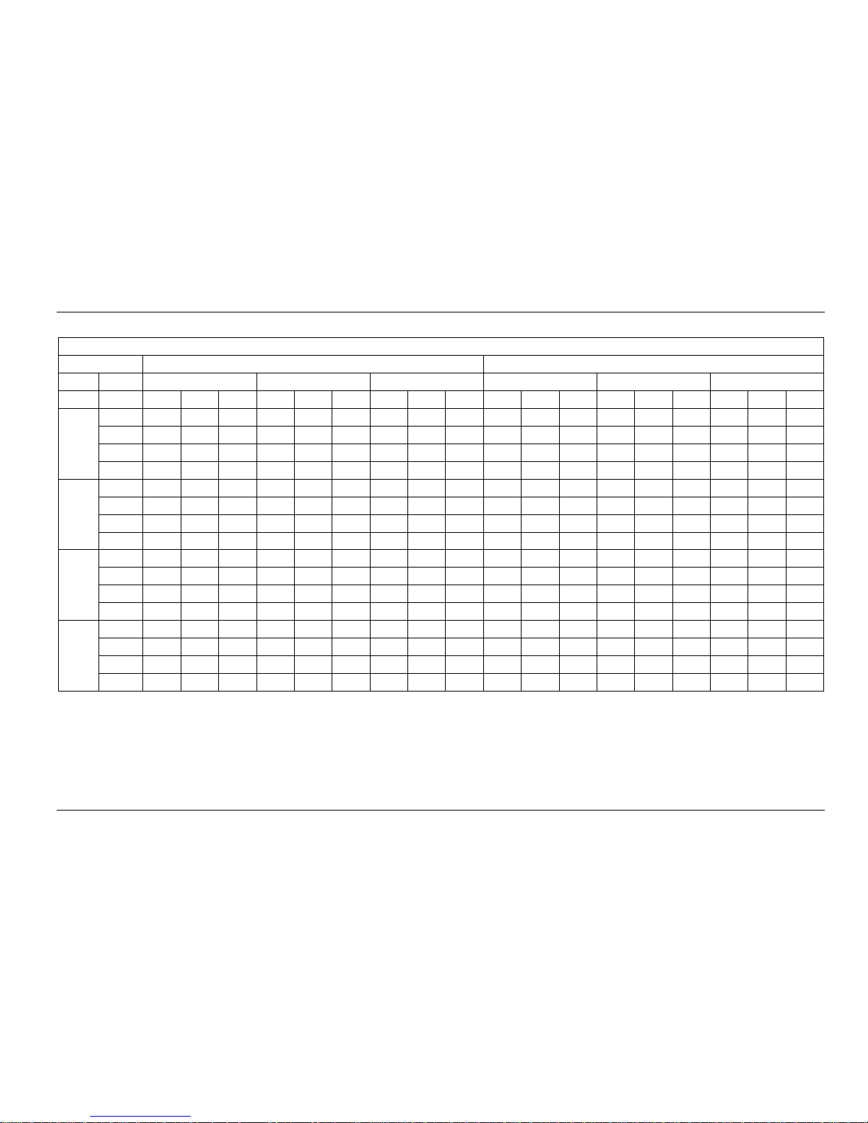
7.1.2 MTA-76HRN1
Gross Cooling Capacity (kW)
Outdoor DB(°C) 29.40 35.00
Indoor WB(°C) 16.10 19.40 22.80 16.10 19.40 22.80
CFM DB(°C) TGC SHC PI TGC SHC PI TGC SHC PI TGC SHC PI TGC SHC PI TGC SHC PI
2000
23.9 19.2 15.0 6.38 21.6 12.2 6.58 23.0 5.3 6.71 18.4 15.1 6.81 20.5 11.6 7.04 21.7 5.0 7.18
26.7 19.9 17.2 6.40 22.1 14.3 6.60 23.5 10.1 6.73 18.8 17.1 6.83 20.9 13.5 7.06 22.2 9.6 7.20
29.4 20.6 18.7 6.42 22.5 18.5 6.62 23.9 14.3 6.75 19.2 18.4 6.85 21.3 17.5 7.08 22.6 13.5 7.22
32.2 21.3 20.9 6.43 23.0 20.9 6.63 24.4 18.0 6.76 19.6 19.2 6.86 21.7 19.7 7.10 23.1 17.0 7.24
2300
23.9 20.3 16.2 6.58 22.3 12.9 6.78 23.6 5.6 6.91 19.4 16.3 7.01 21.1 12.2 7.24 22.4 5.3 7.38
26.7 21.0 18.3 6.60 22.7 16.1 6.80 24.1 10.6 6.93 19.8 18.3 7.03 21.5 15.2 7.26 22.8 10.0 7.40
29.4 21.7 20.1 6.62 23.2 19.5 6.82 24.6 15.0 6.95 20.2 19.8 7.05 21.9 18.4 7.28 23.3 14.2 7.42
32.2 22.5 21.4 6.63 23.6 21.9 6.83 25.1 18.7 6.96 20.6 20.6 7.07 22.4 20.7 7.30 23.7 17.7 7.44
2500
23.9 20.8 18.1 6.82 22.7 14.2 7.15 24.1 6.2 7.15 19.9 18.3 7.25 21.6 13.5 7.48 22.8 5.9 7.62
26.7 21.5 20.5 6.84 23.2 17.8 7.04 24.6 11.8 7.17 20.3 20.3 7.27 22.0 16.9 7.50 23.3 11.1 7.64
29.4 22.3 21.6 6.86 23.7 21.7 7.06 25.1 16.6 7.19 20.7 20.7 7.29 22.4 20.6 7.52 23.8 15.7 7.66
32.2 23.0 22.6 6.87 24.1 21.9 7.08 25.6 20.8 7.21 21.1 21.1 7.31 22.9 20.8 7.54 24.2 19.7 7.68
2800
23.9 21.3 18.8 7.13 23.2 13.9 7.33 24.6 6.0 7.46 20.7 18.3 7.56 22.1 13.2 7.79 23.3 5.7 7.93
26.7 22.0 21.2 7.15 23.7 17.4 7.35 25.1 11.4 7.48 21.1 20.3 7.58 22.5 16.5 7.81 23.8 10.8 7.95
29.4 22.8 22.1 7.17 24.2 21.0 7.37 25.6 16.2 7.50 21.5 21.5 7.60 23.0 20.0 7.83 24.3 15.4 7.97
32.2 23.6 23.1 7.19 24.7 23.7 7.39 26.1 20.2 7.52 22.0 22.0 7.62 23.4 22.5 7.85 24.8 19.2 7.99
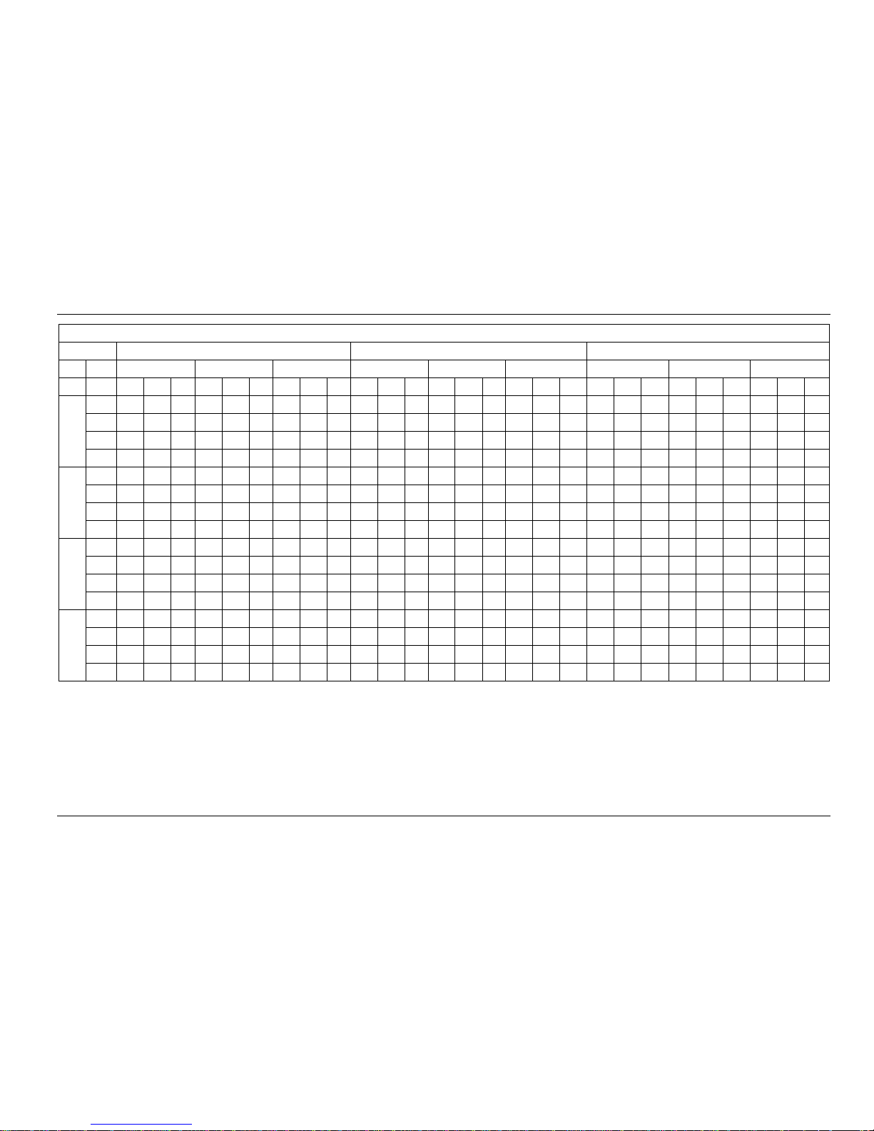
Page 23
Air-cooled Package DM13-01.01.16en
22 Service manual
Gross Cooling Capacity (kW)
Outdoor DB(°C) 40.60 46.10 51.70
Indoor WB(°C) 16.10 19.40 22.80 16.10 19.40 22.80 16.10 19.40
22.80
CFM DB(°C) TGC SHC PI TGC SHC PI TGC SHC PI TGC SHC PI TGC SHC PI TGC SHC PI TGC SHC PI TGC SHC PI TGC SHC PI
2000
23.9 17.2 14.1 8.01 18.7 10.6 8.25 20.0 4.6 8.40 15.7 12.9 8.20 17.2 9.7 8.46 18.4 4.2 8.71 15.2 12.5 8.76 16.5 9.3 9.12 17.6 4.1 9.37
26.7 17.5 15.9 8.03 19.1 12.4 8.27 20.4 8.8 8.42 16.0 14.6 8.22 17.5 11.3 8.48 18.7 8.1 8.73 15.5 14.1 8.78 16.8 10.9 9.14 17.9 7.7 9.39
29.4 17.9 17.2 8.05 19.5 16.0 8.29 20.8 12.4 8.44 16.3 15.7 8.24 17.9 14.6 8.50 19.1 11.4 8.75 15.8 15.2 8.80 17.2 14.1 9.16 18.3 10.9 9.41
32.2 18.2 17.9 8.07 19.9 18.1 8.31 21.2 15.6 8.46 16.7 16.3 8.26 18.2 16.6 8.52 19.5 14.3 8.77 16.1 15.8 8.82 17.5 15.9 9.19 18.6 13.7 9.44
2300
23.9 17.8 14.9 8.21 19.4 11.2 8.45 20.6 4.9 8.60 16.3 13.7 8.40 17.8 10.3 8.66 19.0 4.5 8.91 15.8 13.3 8.96 17.1 9.9 9.32 18.2 4.3 9.57
26.7 18.1 16.8 8.23 19.7 14.0 8.47 21.0 9.2 8.62 16.6 15.4 8.42 18.1 12.9 8.68 19.3 8.5 8.93 16.1 14.9 8.98 17.4 12.4 9.34 18.5 8.1 9.59
29.4 18.5 18.1 8.25 20.1 16.9 8.49 21.5 13.1 8.64 17.0 16.6 8.44 18.5 15.5 8.70 19.7 12.0 8.95 16.5 16.1 9.00 17.8 14.9 9.36 18.9 11.5 9.61
32.2 18.9 18.9 8.27 20.5 19.0 8.51 21.9 16.3 8.66 17.3 17.3 8.46 18.9 17.5 8.72 20.1 15.0 8.97 16.8 16.8 9.02 18.1 16.8 9.39 19.3 14.4 9.64
2500
23.9 18.3 16.8 7.91 19.8 12.4 8.30 21.1 5.5 8.30 16.8 15.4 8.64 18.3 11.4 8.90 19.5 5.0 9.15 16.3 15.0 9.20 17.6 11.0 9.56 18.7 4.8 9.81
26.7 18.6 18.6 7.93 20.2 15.6 8.17 21.5 10.3 8.32 17.1 17.1 8.66 18.6 14.3 8.92 19.8 9.5 9.17 16.6 16.6 9.22 17.9 13.8 9.58 19.0 9.1 9.83
29.4 19.0 19.0 7.95 20.6 18.9 8.19 22.0 14.6 8.34 17.5 17.5 8.68 19.0 17.4 8.94 20.2 13.4 9.19 17.0 17.0 9.24 18.3 16.8 9.60 19.4 12.9 9.85
32.2 19.4 19.4 7.97 21.1 19.1 8.21 22.4 18.2 8.36 17.8 17.8 8.70 19.4 17.6 8.96 20.6 16.8 9.22 17.3 17.3 9.27 18.7 17.0 9.63 19.8 16.1 9.88
2800
23.9 18.8 16.6 8.76 20.3 12.2 9.00 21.6 5.3 9.15 17.3 15.3 8.95 18.8 11.2 9.21 19.9 4.9 9.46 16.8 14.9 9.51 18.1 10.8 9.87 19.2 4.7 10.11
26.7 19.1 18.4 8.78 20.7 15.3 9.02 22.0 10.0 9.17 17.6 17.0 8.97 19.1 14.1 9.23 20.3 9.2 9.48 17.1 16.5 9.53 18.4 13.6 9.89 19.5 8.9 10.14
29.4 19.5 19.5 8.80 21.2 18.4 9.04 22.5 14.2 9.19 18.0 18.0 8.99 19.5 17.0 9.25 20.7 13.1 9.50 17.5 17.5 9.55 18.8 16.4 9.91 19.9 12.6 10.17
32.2 19.9 19.9 8.82 21.6 20.7 9.07 22.9 17.8 9.22 18.4 18.4 9.01 19.9 19.1 9.28 21.2 16.4 9.53 17.8 17.8 9.58 19.2 18.4 9.94 20.3 15.8 10.19
Notes:
1. DB = Dry Bulb Temperature (°C), WB = Wet Bulb Temperature (°C)
4. TGC = Total Cooling Capacity (kW)
5. SHC = Sensible Heating Capacity (kW)
6. PI = Power Input (kW)
Page 24
DM13-01.01.16en Air-cooled Package
Service manual 23
7.1.3 MTA-96CRN1
Gross Cooling Capacity (kW)
Outdoor DB(°C) 29.40 35.00
Indoor WB(°C) 16.10 19.40 22.80 16.10 19.40 22.80
CFM DB(°C) TGC SHC PI TGC SHC PI TGC SHC PI TGC SHC PI TGC SHC PI TGC SHC PI
2440
23.9 25.3 19.8 8.50 27.8 15.7 8.70 29.2 6.7 8.83 24.6 20.2 8.93 26.6 15.1 9.16 27.9 6.4 9.30
26.7 26.2 22.6 8.52 28.4 18.4 8.72 29.8 12.8 8.85 25.1 22.8 8.95 27.2 17.6 9.18 28.5 12.3 9.32
29.4 27.1 24.7 8.54 28.9 23.7 8.74 30.4 18.1 8.87 25.6 24.6 8.97 27.7 22.7 9.20 29.0 17.3 9.34
32.2 28.1 27.5 8.56 29.5 26.8 8.76 31.0 22.8 8.89 26.1 25.6 8.99 28.3 25.7 9.23 29.6 21.8 9.37
2740
23.9 26.4 21.1 8.70 28.4 16.4 8.90 29.8 7.0 9.03 25.6 21.5 9.13 27.3 15.8 9.36 28.5 6.7 9.50
26.7 27.3 23.7 8.72 29.0 20.6 8.92 30.4 13.3 9.05 26.1 24.2 9.15 27.8 19.7 9.38 29.1 12.8 9.52
29.4 28.3 26.2 8.74 29.6 24.9 8.94 31.0 18.9 9.07 26.6 26.1 9.17 28.4 23.8 9.40 29.7 18.1 9.54
32.2 29.2 27.9 8.76 30.2 27.9 8.96 31.6 23.6 9.10 27.2 27.2 9.20 28.9 26.8 9.43 30.3 22.6 9.57
3000
23.9 26.9 23.4 8.94 28.9 18.1 9.27 30.3 7.8 9.27 26.1 23.9 9.37 27.7 17.3 9.55 29.0 7.5 9.74
26.7 27.8 26.5 8.96 29.5 22.7 9.16 30.9 14.8 9.29 26.6 26.6 9.39 28.0 21.8 9.60 29.6 14.2 9.76
29.4 28.8 27.9 8.98 30.1 27.6 9.18 31.5 20.9 9.31 27.1 27.1 9.41 28.9 26.5 9.64 30.2 20.0 9.78
32.2 29.8 29.2 9.00 30.7 27.9 9.21 32.1 26.1 9.34 27.7 27.7 9.44 29.4 26.8 9.67 30.8 25.0 9.81
3240
23.9 27.3 24.2 9.25 29.4 17.6 9.45 30.8 7.5 9.58 26.9 23.8 9.68 28.2 16.9 9.91 29.5 7.2 10.04
26.7 28.3 27.2 9.27 30.0 22.1 9.47 31.4 14.3 9.60 27.4 26.3 9.70 28.8 21.2 9.93 30.1 13.7 10.07
29.4 29.3 28.4 9.29 30.6 26.6 9.49 32.0 20.3 9.62 27.9 27.9 9.72 29.4 25.5 9.95 30.7 19.4 10.10
32.2 30.3 29.7 9.32 31.2 30.0 9.52 32.7 25.3 9.65 28.5 28.5 9.75 30.0 28.8 9.98 31.3 24.3 10.12
Page 25
Air-cooled Package DM13-01.01.16en
24 Service manual
Gross Cooling Capacity (kW)
Outdoor DB(°C) 40.60 46.10 51.70
Indoor WB(°C) 16.10 19.40 22.80 16.10 19.40 22.80 16.10 19.40
22.80
CFM DB(°C) TGC SHC PI TGC SHC PI TGC SHC PI TGC SHC PI TGC SHC PI TGC SHC PI TGC SHC PI TGC SHC PI TGC SHC PI
2440
23.9 22.0 18.0 10.63 23.6 13.3 10.87 24.8 5.7 11.02 20.5 16.8 10.82 22.0 12.4 11.08 23.2 5.4 11.33 20.0 16.4 11.42 21.3 12.0 11.78 22.4 5.2 12.03
26.7 22.4 20.4 10.66 24.0 15.6 10.90 25.3 10.9 11.05 20.9 19.0 10.85 22.4 14.5 11.11 23.6 10.2 11.36 20.4 18.6 11.45 21.7 14.1 11.81 22.8 9.8 12.06
29.4 22.9 22.0 10.69 24.5 20.1 10.93 25.8 15.4 11.08 21.3 20.5 10.88 22.9 18.8 11.14 24.1 14.3 11.39 20.8 20.0 11.48 22.2 18.2 11.84 23.3 13.9 12.09
32.2 23.3 22.9 10.71 25.0 22.7 10.95 26.4 19.4 11.11 21.8 21.3 10.90 23.3 21.2 11.17 24.6 18.1 11.42 21.3 20.8 11.51 22.6 20.6 11.87 23.8 17.5 12.12
2740
23.9 22.6 19.0 10.83 24.2 14.0 11.07 25.4 6.0 11.22 21.1 17.8 11.02 22.6 13.1 11.28 23.8 5.6 11.53 20.6 17.3 11.62 21.9 12.7 11.98 23.0 5.4 12.23
26.7 23.1 21.3 10.86 24.7 17.5 11.10 26.0 11.4 11.25 21.6 20.0 11.05 23.1 16.3 11.31 24.3 10.6 11.56 21.1 19.5 11.65 22.4 15.9 12.01 23.5 10.3 12.26
29.4 23.5 23.1 10.89 25.1 21.1 11.13 26.5 16.1 11.28 22.0 21.6 11.08 23.5 19.8 11.34 24.7 15.1 11.59 21.5 21.1 11.68 22.8 19.2 12.04 23.9 14.6 12.29
32.2 24.0 24.0 10.91 25.6 23.7 11.16 27.0 20.1 11.31 22.4 22.4 11.11 24.0 22.2 11.37 25.2 18.8 11.62 21.9 21.9 11.71 23.3 21.5 12.07 24.4 18.2 12.32
3000
23.9 23.1 21.2 11.07 24.7 15.4 11.46 25.9 6.7 11.46 21.6 19.8 11.26 23.1 14.4 11.52 24.3 6.3 11.77 21.1 19.4 11.86 22.4 14.0 12.22 23.5 6.1 12.47
26.7 23.6 23.6 11.10 25.2 19.3 11.34 26.5 12.7 11.49 22.1 22.1 11.29 23.6 18.1 11.55 24.8 11.8 11.80 21.6 21.6 11.89 22.9 17.6 12.25 24.0 11.5 12.50
29.4 24.0 24.0 11.13 25.7 23.5 11.37 27.0 17.9 11.52 22.5 22.5 11.32 24.0 22.0 11.58 25.2 16.7 11.83 22.0 22.0 11.92 23.3 21.4 12.28 24.4 16.2 12.53
32.2 24.5 24.5 11.16 26.2 23.8 11.40 27.5 22.4 11.55 22.9 22.9 11.35 24.5 22.3 11.61 25.7 20.9 11.86 22.4 22.4 11.95 23.8 21.6 12.31 24.9 20.3 12.56
3240
23.9 23.6 20.9 11.38 25.1 15.1 11.62 26.4 6.5 11.77 22.1 19.6 11.57 23.6 14.1 11.83 24.8 6.1 12.08 21.6 19.1 12.17 22.9 13.7 12.53 24.0 5.9 12.78
26.7 24.1 23.1 11.41 25.7 18.9 11.65 27.0 12.3 11.80 22.6 21.7 11.60 24.1 17.7 11.86 25.3 11.5 12.11 22.1 21.2 12.20 23.4 17.2 12.56 24.5 11.1 12.81
29.4 24.5 24.5 11.44 26.2 22.8 11.68 27.5 17.4 11.83 23.0 23.0 11.63 24.5 21.3 11.89 25.8 16.3 12.14 22.5 22.5 12.23 23.8 20.7 12.59 24.9 15.8 12.84
32.2 25.0 25.0 11.47 26.7 25.7 11.71 28.0 21.7 11.86 23.5 23.5 11.66 25.0 24.1 11.92 26.3 20.4 12.17 22.9 22.9 12.26 24.3 23.4 12.62 25.4 19.7 12.87
Notes:
1. DB = Dry Bulb Temperature (°C), WB = Wet Bulb Temperature (°C)
4. TGC = Total Cooling Capacity (kW)
5. SHC = Sensible Heating Capacity (kW)
6. PI = Power Input (kW)
Page 26

DM13-01.01.16en Air-cooled Package
Service manual 25
7.1.4 MTA-96HRN1
Gross Cooling Capacity (kW)
Outdoor DB(°C) 29.40 35.00
Indoor WB(°C) 16.10 19.40 22.80 16.10 19.40 22.80
CFM DB(°C) TGC SHC PI TGC SHC PI TGC SHC PI TGC SHC PI TGC SHC PI TGC SHC PI
2440
23.9 24.9 19.4 8.47 27.4 15.5 8.67 28.8 6.6 8.80 24.2 19.8 8.90 26.2 14.8 9.13 27.5 6.3 9.27
26.7 25.8 22.2 8.49 27.9 18.1 8.69 29.3 12.6 8.82 24.7 22.4 8.92 26.7 17.3 9.15 28.0 12.1 9.29
29.4 26.7 24.2 8.51 28.5 23.4 8.71 29.9 17.8 8.84 25.1 24.2 8.94 27.3 22.3 9.17 28.6 17.0 9.31
32.2 27.6 27.0 8.53 29.1 26.4 8.73 30.5 22.4 8.86 25.6 25.1 8.96 27.8 25.3 9.20 29.2 21.4 9.34
2740
23.9 25.9 20.8 8.67 28.0 16.2 8.87 29.4 6.9 9.00 25.1 21.1 9.10 26.8 15.5 9.33 28.1 6.6 9.47
26.7 26.9 23.3 8.69 28.6 20.2 8.89 30.0 13.1 9.02 25.7 23.8 9.12 27.4 19.4 9.35 28.7 12.6 9.49
29.4 27.8 25.7 8.71 29.1 24.5 8.91 30.5 18.6 9.04 26.2 25.7 9.14 27.9 23.4 9.37 29.2 17.8 9.51
32.2 28.8 27.4 8.73 29.7 27.5 8.93 31.2 23.3 9.07 26.7 26.7 9.17 28.5 26.3 9.40 29.8 22.2 9.54
3000
23.9 26.4 23.0 8.91 28.5 17.8 9.24 29.9 7.7 9.24 25.6 23.5 9.34 27.3 17.1 9.57 28.6 7.4 9.71
26.7 27.4 26.0 8.93 29.1 22.3 9.13 30.5 14.6 9.26 26.2 26.2 9.36 28.0 21.4 9.60 29.2 13.9 9.73
29.4 28.3 27.5 8.95 29.6 27.2 9.15 31.1 20.6 9.28 26.7 26.7 9.38 28.4 26.1 9.61 29.7 19.7 9.75
32.2 29.3 28.7 8.97 30.2 27.5 9.18 31.7 25.8 9.31 27.2 27.2 9.41 29.0 26.3 9.64 30.3 24.7 9.78
3240
23.9 26.9 23.8 9.22 29.0 17.3 9.42 30.3 7.4 9.55 26.4 23.4 9.65 27.8 16.6 9.88 29.1 7.1 10.01
26.7 27.9 26.8 9.24 29.6 21.7 9.44 31.0 14.1 9.57 27.0 25.9 9.67 28.4 20.8 9.90 29.7 13.5 10.04
29.4 28.8 28.0 9.26 30.1 26.2 9.46 31.6 20.0 9.59 27.5 27.5 9.69 28.9 25.1 9.92 30.2 19.1 10.07
32.2 29.8 29.2 9.29 30.7 29.6 9.49 32.2 25.0 9.62 28.0 28.0 9.72 29.5 28.4 9.95 30.8 23.9 10.09
Page 27
Air-cooled Package DM13-01.01.16en
26 Service manual
Gross Cooling Capacity (kW)
Outdoor DB(°C) 40.60 46.10 51.70
Indoor WB(°C) 16.10 19.40 22.80 16.10 19.40 22.80 16.10 19.40
22.80
CFM DB(°C) TGC SHC PI TGC SHC PI TGC SHC PI TGC SHC PI TGC SHC PI TGC SHC PI TGC SHC PI TGC SHC PI TGC SHC PI
2440
23.9 22.0 18.0 10.83 23.5 13.3 11.07 24.8 5.7 11.22 20.5 16.8 11.02 22.0 12.4 11.28 23.1 5.3 11.53 19.4 15.9 11.52 20.7 11.7 11.88 21.8 5.0 12.13
26.7 22.4 20.4 10.86 24.0 15.5 11.10 25.3 10.9 11.25 20.9 19.0 11.05 22.4 14.5 11.31 23.6 10.2 11.56 19.8 18.0 11.55 21.1 13.7 11.91 22.2 9.6 12.16
29.4 22.8 22.0 10.89 24.5 20.1 11.13 25.8 15.4 11.28 21.3 20.5 11.08 22.8 18.7 11.34 24.1 14.3 11.59 20.2 19.4 11.58 21.5 17.6 11.94 22.7 13.5 12.19
32.2 23.3 22.8 10.91 25.0 22.7 11.16 26.3 19.4 11.31 21.7 21.3 11.11 23.3 21.2 11.37 24.6 18.1 11.62 20.6 20.2 11.61 22.0 20.0 11.97 23.1 17.0 12.22
2740
23.9 22.6 19.0 11.03 24.1 14.0 11.27 25.4 6.0 11.42 21.1 17.7 11.22 22.6 13.0 11.48 23.7 5.6 11.73 20.0 16.8 11.72 21.3 12.3 12.08 22.4 5.3 12.33
26.7 23.0 21.3 11.06 24.6 17.5 11.30 25.9 11.4 11.45 21.5 19.9 11.25 23.0 16.3 11.51 24.2 10.6 11.76 20.4 18.9 11.75 21.7 15.4 12.11 22.8 10.0 12.36
29.4 23.5 23.0 11.09 25.1 21.1 11.33 26.4 16.1 11.48 22.0 21.5 11.28 23.5 19.7 11.54 24.7 15.1 11.79 20.8 20.4 11.78 22.2 18.6 12.14 23.3 14.2 12.39
32.2 24.0 24.0 11.12 25.6 23.7 11.36 27.0 20.1 11.51 22.4 22.4 11.31 24.0 22.2 11.57 25.2 18.8 11.82 21.3 21.3 11.81 22.6 20.9 12.17 23.8 17.7 12.42
3000
23.9 23.1 21.2 11.27 24.6 15.4 11.66 25.9 6.7 11.66 21.6 19.8 11.46 23.1 14.4 11.72 24.2 6.3 11.97 20.5 18.8 11.96 21.8 13.6 12.32 22.9 5.9 12.57
26.7 23.5 23.5 11.30 25.1 19.3 11.54 26.4 12.6 11.69 22.0 22.0 11.49 23.3 18.1 11.75 24.7 11.8 12.00 20.9 20.9 11.99 22.2 17.1 12.35 23.3 11.2 12.60
29.4 24.0 24.0 11.33 25.6 23.5 11.57 26.9 17.8 11.72 22.5 22.5 11.52 24.0 22.0 11.78 25.2 16.7 12.03 21.3 21.3 12.02 22.7 20.8 12.38 23.8 15.8 12.63
32.2 24.5 24.5 11.36 26.1 23.8 11.60 27.5 22.3 11.75 22.9 22.9 11.55 24.5 22.2 11.81 25.7 20.9 12.06 21.8 21.8 12.05 23.1 21.0 12.41 24.3 19.7 12.66
3240
23.9 23.5 20.8 11.58 25.1 15.0 11.82 26.4 6.5 11.97 22.1 19.5 11.77 23.5 14.1 12.03 24.7 6.1 12.28 21.0 18.6 12.27 22.3 13.3 12.63 23.4 5.7 12.88
26.7 24.0 23.1 11.61 25.6 18.8 11.85 26.9 12.2 12.00 22.5 21.7 11.80 24.0 17.7 12.06 25.2 11.5 12.31 21.4 20.6 12.30 22.7 16.7 12.66 23.8 10.8 12.91
29.4 24.5 24.5 11.64 26.1 22.7 11.88 27.5 17.4 12.03 23.0 23.0 11.83 24.5 21.3 12.09 25.7 16.3 12.34 21.9 21.9 12.33 23.2 20.2 12.69 24.3 15.4 12.94
32.2 25.0 25.0 11.67 26.7 25.6 11.91 28.0 21.7 12.06 23.4 23.4 11.86 25.0 24.0 12.12 26.2 20.3 12.37 22.3 22.3 12.36 23.6 22.7 12.72 24.8 19.2 12.97
Notes:
1. DB = Dry Bulb Temperature (°C), WB = Wet Bulb Temperature (°C)
4. TGC = Total Cooling Capacity (kW)
5. SHC = Sensible Heating Capacity (kW)
6. PI = Power Input (kW)
Page 28
DM13-01.01.16en Air-cooled Package
Service manual 27
7.1.5 MTA-120CRN1
Gross Cooling Capacity (kW)
Outdoor DB(°C) 29.40 35.00
Indoor WB(°C) 16.10 19.40 22.80 16.10 19.40 22.80
CFM DB(°C) TGC SHC PI TGC SHC PI TGC SHC PI TGC SHC PI TGC SHC PI TGC SHC PI
3200
23.9 32.0 25.0 10.99 34.6 19.5 11.19 36.0 8.3 11.32 31.4 25.7 11.42 33.4 18.9 11.65 34.7 8.0 11.79
26.7 33.1 28.5 11.02 35.3 22.8 11.22 36.7 15.8 11.35 32.0 29.1 11.45 34.1 22.1 11.68 35.4 15.3 11.82
29.4 34.3 31.1 11.05 36.0 29.5 11.25 37.4 22.3 11.38 32.6 31.4 11.48 34.8 28.5 11.71 36.1 21.5 11.85
32.2 35.5 34.8 11.08 36.7 33.4 11.28 38.2 28.1 11.41 33.3 32.6 11.51 35.5 32.2 11.74 36.8 27.1 11.88
3500
23.9 33.0 26.4 11.19 35.2 20.3 11.39 36.6 8.6 11.52 32.4 27.2 11.62 34.0 19.7 11.85 35.3 8.3 11.99
26.7 34.2 29.7 11.22 35.9 25.5 11.42 37.3 16.4 11.55 33.0 30.6 11.65 34.7 24.6 11.88 36.0 15.8 12.02
29.4 35.4 32.8 11.25 36.6 30.8 11.45 38.0 23.2 11.58 33.7 33.0 11.68 35.4 29.7 11.91 36.7 22.4 12.05
32.2 36.6 34.9 11.28 37.4 34.6 11.48 38.8 29.0 11.61 34.3 34.3 11.71 36.1 33.4 11.94 37.5 28.0 12.08
3750
23.9 33.5 29.2 11.43 35.7 22.3 11.76 37.1 9.6 11.76 32.8 30.1 11.86 34.5 21.6 11.98 35.8 9.3 12.23
26.7 34.7 33.0 11.46 36.4 28.0 11.66 37.8 18.1 11.79 33.5 33.5 11.89 35.0 27.1 12.00 36.5 17.5 12.26
29.4 35.9 34.9 11.49 37.1 34.1 11.69 38.6 25.5 11.82 34.2 34.2 11.92 35.9 32.9 12.15 37.2 24.7 12.29
32.2 37.2 36.4 11.52 37.9 34.4 11.72 39.3 32.0 11.85 34.9 34.9 11.95 36.6 33.3 12.18 38.0 30.9 12.32
4000
23.9 34.0 30.1 11.74 36.2 21.7 11.94 37.5 9.2 12.07 33.6 29.8 12.17 35.0 21.0 12.40 36.3 8.9 12.54
26.7 35.2 33.8 11.77 36.9 27.1 11.97 38.3 17.4 12.10 34.3 33.0 12.20 35.7 26.3 12.43 37.0 16.8 12.57
29.4 36.4 35.4 11.80 37.6 32.7 12.00 39.1 24.7 12.13 35.0 35.0 12.23 36.4 31.7 12.46 37.7 23.9 12.60
32.2 37.7 37.0 11.83 38.4 36.9 12.03 39.8 30.9 12.16 35.7 35.7 12.26 37.1 35.7 12.49 38.5 29.8 12.63
Page 29

Air-cooled Package DM13-01.01.16en
28 Service manual
Gross Cooling Capacity (kW)
Outdoor DB(°C) 40.60 46.10 51.70
Indoor WB(°C) 16.10 19.40 22.80 16.10 19.40 22.80 16.10 19.40
22.80
CFM DB(°C) TGC SHC PI TGC SHC PI TGC SHC PI TGC SHC PI TGC SHC PI TGC SHC PI TGC SHC PI TGC SHC PI TGC SHC PI
3200
23.9 23.9 28.3 23.2 12.33 29.9 16.9 12.57 31.1 7.2 12.72 26.8 22.0 12.52 28.3 16.0 12.78 29.5 6.8 13.03 26.5 21.8 14.01 27.8 15.7 14.37 28.9 6.7
26.7 26.7 28.9 26.2 12.36 30.5 19.7 12.60 31.8 13.7 12.75 27.4 24.9 12.55 28.9 18.7 12.81 30.1 13.0 13.06 27.1 24.6 14.05 28.4 18.4 14.41 29.5 12.7
29.4 29.4 29.4 28.3 12.39 31.1 25.5 12.63 32.4 19.3 12.78 27.9 26.8 12.58 29.4 24.1 12.84 30.7 18.3 13.09 27.6 26.6 14.09 28.9 23.7 14.45 30.1 17.9
32.2 32.2 30.0 29.4 12.42 31.7 28.8 12.66 33.0 24.3 12.81 28.5 27.9 12.61 30.0 27.3 12.87 31.3 23.0 13.13 28.2 27.6 14.12 29.5 26.8 14.48 30.7 22.6
3500
23.9 23.9 28.9 24.3 12.53 30.5 17.6 12.77 31.7 7.5 12.92 27.4 23.1 12.72 28.9 16.7 12.98 30.1 7.1 13.23 27.2 22.8 14.21 28.4 16.4 14.57 29.5 7.0
26.7 26.7 29.5 27.3 12.56 31.1 22.0 12.80 32.4 14.2 12.95 28.0 25.9 12.75 29.5 20.9 13.01 30.7 13.5 13.26 27.7 25.6 14.25 29.0 20.6 14.61 30.1 13.2
29.4 29.4 30.1 29.5 12.59 31.7 26.6 12.83 33.0 20.1 12.98 28.5 28.0 12.78 30.1 25.3 13.04 31.3 19.1 13.29 28.3 27.7 14.29 29.6 24.9 14.65 30.7 18.7
32.2 32.2 30.7 30.7 12.62 32.3 29.9 12.86 33.7 25.1 13.01 29.1 29.1 12.81 30.7 28.4 13.08 31.9 23.8 13.33 28.8 28.8 14.32 30.2 27.9 14.68 31.3 23.4
3750
23.9 23.9 29.4 27.0 12.23 31.0 19.4 12.62 32.2 8.4 12.62 27.9 25.6 12.96 29.4 18.4 13.22 30.6 7.9 13.47 27.6 25.4 14.45 28.9 18.1 14.81 30.0 7.8
26.7 26.7 30.0 30.0 12.26 31.6 24.3 12.50 32.9 15.7 12.65 28.5 28.5 12.99 30.0 23.1 13.25 31.2 14.9 13.50 28.2 28.2 14.49 29.5 22.7 14.85 30.6 14.6
29.4 29.4 30.6 30.6 12.29 32.2 29.6 12.53 33.5 22.2 12.68 29.0 29.0 13.02 30.6 28.1 13.28 31.8 21.1 13.53 28.8 28.8 14.53 30.1 27.6 14.89 31.2 20.7
32.2 32.2 31.2 31.2 12.32 32.9 29.9 12.56 34.2 27.8 12.71 29.6 29.6 13.06 31.2 28.4 13.32 32.4 26.4 13.57 29.3 29.3 14.56 30.7 27.9 14.92 31.8 25.9
4000
23.9 23.9 29.9 26.4 13.08 31.5 18.8 13.32 32.7 8.0 13.47 28.4 25.1 13.27 29.9 17.9 13.53 31.1 7.6 13.78 28.1 24.9 14.76 29.4 17.6 15.12 30.5 7.5
26.7 26.7 30.5 29.3 13.11 32.1 23.6 13.35 33.4 15.2 13.50 29.0 27.9 13.30 30.5 22.4 13.56 31.7 14.4 13.81 28.7 27.6 14.80 30.0 22.1 15.16 31.1 14.1
29.4 29.4 31.1 31.1 13.14 32.7 28.5 13.38 34.0 21.5 13.53 29.6 29.6 13.33 31.1 27.0 13.59 32.3 20.5 13.84 29.3 29.3 14.84 30.6 26.6 15.20 31.7 20.1
32.2 32.2 31.7 31.7 13.18 33.4 32.1 13.42 34.7 26.9 13.57 30.2 30.2 13.37 31.7 30.5 13.63 33.0 25.6 13.88 29.9 29.9 14.87 31.2 30.0 15.24 32.4 25.1
Notes:
1. DB = Dry Bulb Temperature (°C), WB = Wet Bulb Temperature (°C)
4. TGC = Total Cooling Capacity (kW)
5. SHC = Sensible Heating Capacity (kW)
6. PI = Power Input (kW)
Page 30

DM13-01.01.16en Air-cooled Package
Service manual 29
7.1.6 MTA-120HR
Gross Cooling Capacity (kW)
Outdoor DB(°C) 29.40 35.00
Indoor WB(°C) 16.10 19.40 22.80 16.10 19.40 22.80
CFM DB(°C) TGC SHC PI TGC SHC PI TGC SHC PI TGC SHC PI TGC SHC PI TGC SHC PI
3200
23.9 31.8 24.8 10.87 34.4 19.4 11.07 35.8 8.3 11.20 31.2 25.6 11.30 33.2 18.8 11.53 34.5 8.0 11.67
26.7 32.9 28.4 10.90 35.1 22.7 11.10 36.5 15.7 11.23 31.8 28.9 11.33 33.9 21.9 11.56 35.2 15.2 11.70
29.4 34.1 31.0 10.93 35.8 29.3 11.13 37.2 22.1 11.26 32.4 31.2 11.36 34.6 28.3 11.59 35.9 21.4 11.73
32.2 35.2 34.6 10.95 36.5 33.2 11.16 38.0 27.9 11.29 33.1 32.4 11.39 35.2 32.0 11.62 36.6 26.9 11.76
3500
23.9 32.9 26.3 11.07 35.0 20.2 11.27 36.4 8.6 11.40 32.2 27.0 11.50 33.8 19.6 11.73 35.1 8.3 11.87
26.7 34.0 29.6 11.10 35.7 25.3 11.30 37.1 16.3 11.43 32.8 30.4 11.53 34.5 24.5 11.76 35.8 15.7 11.90
29.4 35.2 32.6 11.13 36.4 30.6 11.33 37.8 23.1 11.46 33.5 32.8 11.56 35.2 29.6 11.79 36.5 22.3 11.93
32.2 36.4 34.7 11.16 37.1 34.4 11.36 38.6 28.8 11.49 34.1 34.1 11.59 35.9 33.2 11.82 37.2 27.8 11.96
3750
23.9 33.3 29.0 11.31 35.5 22.2 11.64 36.9 9.5 11.64 32.6 30.0 11.74 34.3 21.4 11.97 35.6 9.2 12.11
26.7 34.5 32.9 11.34 36.2 27.8 11.54 37.6 18.0 11.67 33.3 33.3 11.77 35.0 26.9 12.00 36.3 17.4 12.14
29.4 35.7 34.7 11.37 36.9 33.9 11.57 38.4 25.4 11.70 34.0 34.0 11.80 35.7 32.8 12.03 37.0 24.5 12.17
32.2 37.0 36.2 11.40 37.7 34.2 11.60 39.1 31.8 11.73 34.6 34.6 11.83 36.4 33.1 12.06 37.8 30.7 12.20
4000
23.9 33.8 29.9 11.62 36.0 21.5 11.82 37.4 9.2 11.95 33.4 29.6 12.05 34.8 20.8 12.28 36.1 8.8 12.42
26.7 35.0 33.7 11.65 36.7 27.0 11.85 38.1 17.3 11.98 34.1 32.8 12.08 35.5 26.1 12.31 36.8 16.7 12.45
29.4 36.2 35.2 11.68 37.4 32.6 11.88 38.9 24.6 12.01 34.8 34.8 12.11 36.2 31.5 12.34 37.5 23.8 12.48
32.2 37.5 36.8 11.71 38.2 36.7 11.91 39.6 30.7 12.04 35.5 35.5 12.14 36.9 35.5 12.37 38.3 29.7 12.51
Page 31

Air-cooled Package DM13-01.01.16en
30 Service manual
Gross Cooling Capacity (kW)
Outdoor DB(°C) 40.60 46.10 51.70
Indoor WB(°C) 16.10 19.40 22.80 16.10 19.40 22.80 16.10 19.40
22.80
CFM DB(°C) TGC SHC PI TGC SHC PI TGC SHC PI TGC SHC PI TGC SHC PI TGC SHC PI TGC SHC PI TGC SHC PI TGC SHC PI
3200
23.9 23.9 28.0 22.9 12.73 29.5 16.7 12.97 30.8 7.1 13.12 26.5 21.7 12.92 28.0 15.8 13.18 29.2 6.7 13.43 26.2 21.4 14.72 27.4 15.5 15.08 28.5 6.6
26.7 26.7 28.5 25.9 12.76 30.1 19.5 13.00 31.4 13.6 13.15 27.0 24.6 12.95 28.5 18.5 13.21 29.7 12.8 13.46 26.7 24.3 14.76 28.0 18.1 15.12 29.1 12.5
29.4 29.4 29.1 28.0 12.79 30.7 25.2 13.03 32.1 19.1 13.18 27.6 26.5 12.98 29.1 23.9 13.24 30.3 18.1 13.49 27.2 26.2 14.80 28.5 23.4 15.16 29.7 17.7
32.2 32.2 29.7 29.1 12.82 31.4 28.5 13.07 32.7 24.1 13.22 28.1 27.6 13.01 29.7 27.0 13.28 30.9 22.8 13.53 27.8 27.2 14.83 29.1 26.5 15.20 30.3 22.3
3500
23.9 23.9 28.6 24.0 12.93 30.2 17.4 13.17 31.4 7.4 13.32 27.1 22.8 13.12 28.6 16.5 13.38 29.8 7.0 13.63 26.8 22.5 14.92 28.0 16.2 15.28 29.1 6.9
26.7 26.7 29.2 27.0 12.96 30.8 21.8 13.20 32.1 14.1 13.35 27.7 25.6 13.15 29.2 20.7 13.41 30.4 13.3 13.66 27.3 25.3 14.96 28.6 20.3 15.32 29.7 13.0
29.4 29.4 29.7 29.2 12.99 31.4 26.4 13.23 32.7 19.9 13.38 28.2 27.7 13.18 29.7 25.0 13.44 31.0 18.9 13.69 27.9 27.3 15.00 29.2 24.5 15.36 30.3 18.5
32.2 32.2 30.3 30.3 13.02 32.0 29.6 13.27 33.4 24.9 13.42 28.8 28.8 13.22 30.3 28.1 13.48 31.6 23.6 13.73 28.4 28.4 15.03 29.8 27.6 15.40 30.9 23.1
3750
23.9 23.9 29.1 26.7 12.63 30.6 19.2 13.02 31.9 8.3 13.02 27.6 25.3 13.36 29.1 18.2 13.62 30.3 7.8 13.87 27.3 25.0 15.16 28.5 17.8 15.52 29.6 7.7
26.7 26.7 29.7 29.7 12.66 31.3 24.0 12.90 32.6 15.6 13.05 28.2 28.2 13.39 29.7 22.8 13.65 30.9 14.8 13.90 27.8 27.8 15.20 29.1 22.4 15.56 30.2 14.5
29.4 29.4 30.3 30.3 12.69 31.9 29.3 12.93 33.2 22.0 13.08 28.7 28.7 13.42 30.3 27.8 13.68 31.5 20.8 13.93 28.4 28.4 15.24 29.7 27.2 15.60 30.8 20.4
32.2 32.2 30.9 30.9 12.72 32.5 29.6 12.96 33.9 27.5 13.12 29.3 29.3 13.46 30.9 28.1 13.72 32.1 26.1 13.97 28.9 28.9 15.28 30.3 27.5 15.64 31.4 25.6
4000
23.9 23.9 29.6 26.2 13.48 31.1 18.6 13.72 32.4 7.9 13.87 28.1 24.9 13.67 29.6 17.7 13.93 30.7 7.5 14.17 27.8 24.6 15.47 29.0 17.4 15.83 30.1 7.4
26.7 26.7 30.2 29.0 13.51 31.8 23.4 13.75 33.1 15.0 13.90 28.7 27.6 13.70 30.2 22.2 13.96 31.4 14.3 14.21 28.3 27.2 15.51 29.6 21.8 15.87 30.7 14.0
29.4 29.4 30.8 30.8 13.54 32.4 28.2 13.78 33.7 21.3 13.93 29.2 29.2 13.73 30.8 26.8 13.99 32.0 20.2 14.25 28.9 28.9 15.55 30.2 26.3 15.91 31.3 19.8
32.2 32.2 31.4 31.4 13.58 33.0 31.8 13.82 34.4 26.7 13.97 29.8 29.8 13.77 31.4 30.2 14.03 32.6 25.3 14.28 29.5 29.5 15.59 30.8 29.6 15.95 32.0 24.8
Notes:
1. DB = Dry Bulb Temperature (°C), WB = Wet Bulb Temperature (°C)
4. TGC = Total Cooling Capacity (kW)
5. SHC = Sensible Heating Capacity (kW)
6. PI = Power Input (kW)
Page 32

DM13-01.01.16en Air-cooled Package
Service manual 31
7.1.7 MTA-150CRN1
Gross Cooling Capacity (kW)
Outdoor DB(°C) 29.40 35.00
Indoor WB(°C) 16.10 19.40 22.80 16.10 19.40 22.80
CFM DB(°C) TGC SHC PI TGC SHC PI TGC SHC PI TGC SHC PI TGC SHC PI TGC SHC PI
4000
23.9 41.0 32.0 14.20 43.7 24.7 14.40 45.1 10.4 14.53 40.5 33.2 14.63 42.5 24.0 14.86 43.8 10.1 15.00
26.7 42.4 36.6 14.24 44.6 28.9 14.44 46.0 19.8 14.57 41.3 37.5 14.67 43.4 28.1 14.90 44.7 19.3 15.04
29.4 43.9 39.9 14.28 45.5 37.3 14.48 46.9 27.9 14.61 42.1 40.5 14.71 44.2 36.3 14.94 45.6 27.1 15.08
32.2 45.4 44.5 14.31 46.4 42.2 14.51 47.8 35.2 14.64 43.0 42.1 14.74 45.1 41.0 14.97 46.5 34.2 15.12
4300
23.9 42.0 33.6 14.40 44.3 25.6 14.60 45.7 10.8 14.73 41.5 34.8 14.83 43.1 24.9 14.99 44.4 10.5 15.20
26.7 43.5 37.8 14.44 45.2 32.1 14.64 46.6 20.4 14.77 42.3 39.2 14.87 44.0 31.2 15.01 45.3 19.9 15.24
29.4 45.0 41.7 14.48 46.1 38.7 14.68 47.5 29.0 14.81 43.1 42.3 14.91 44.9 37.7 15.03 46.2 28.2 15.28
32.2 46.6 44.4 14.51 47.0 43.5 14.71 48.5 36.2 14.84 44.0 44.0 14.94 45.8 42.4 15.05 47.1 35.2 15.32
4500
23.9 42.5 37.0 14.64 44.8 28.0 14.97 46.2 12.0 14.97 42.0 38.5 15.07 43.6 27.3 15.08 44.9 11.6 15.44
26.7 44.0 41.9 14.68 45.7 35.2 14.88 47.1 22.5 15.01 42.8 42.8 15.11 44.0 34.2 15.10 45.8 21.9 15.48
29.4 45.5 44.2 14.72 46.6 42.8 14.92 48.0 31.8 15.05 43.7 43.7 15.15 45.4 41.6 15.38 46.7 30.9 15.52
32.2 47.1 46.2 14.75 47.5 43.2 14.95 49.0 39.8 15.09 44.5 44.5 15.19 46.3 42.1 15.42 47.7 38.7 15.56
4800
23.9 43.0 38.0 14.95 45.3 27.1 15.15 46.7 11.4 15.28 42.7 37.8 15.38 44.1 26.4 15.61 45.4 11.1 15.75
26.7 44.5 42.8 14.99 46.2 34.0 15.19 47.6 21.6 15.32 43.6 41.9 15.42 45.0 33.1 15.65 46.3 21.0 15.79
29.4 46.1 44.7 15.03 47.1 41.0 15.23 48.6 30.7 15.36 44.5 44.5 15.46 45.9 39.9 15.69 47.2 29.9 15.83
32.2 47.7 46.7 15.07 48.1 46.2 15.27 49.5 38.4 15.40 45.4 45.4 15.50 46.8 45.0 15.73 48.2 37.3 15.87
Page 33

Air-cooled Package DM13-01.01.16en
32 Service manual
Gross Cooling Capacity (kW)
Outdoor DB(°C) 40.60 46.10 51.70
Indoor WB(°C) 16.10 19.40 22.80 16.10 19.40 22.80 16.10 19.40
22.80
CFM DB(°C) TGC SHC PI TGC SHC PI TGC SHC PI TGC SHC PI TGC SHC PI TGC SHC PI TGC SHC PI TGC SHC PI TGC SHC PI
4000
23.9 36.4 29.8 17.07 37.9 21.4 17.31 39.2 9.1 17.46 34.9 28.6 17.26 36.4 20.5 17.52 37.5 8.7 17.77 34.4 28.2 18.43 35.7 20.2 18.79 36.8 8.5 19.04
26.7 37.1 33.7 17.11 38.7 25.1 17.35 40.0 17.2 17.50 35.6 32.3 17.30 37.1 24.0 17.56 38.3 16.5 17.81 35.1 31.9 18.48 36.4 23.6 18.84 37.5 16.2 19.09
29.4 37.8 36.4 17.15 39.5 32.3 17.39 40.8 24.3 17.54 36.3 34.9 17.34 37.8 31.0 17.60 39.0 23.2 17.85 35.8 34.5 18.53 37.2 30.5 18.89 38.3 22.8 19.14
32.2 38.6 37.8 17.20 40.2 36.6 17.44 41.6 30.6 17.59 37.0 36.3 17.39 38.6 35.1 17.65 39.8 29.3 17.90 36.5 35.8 18.57 37.9 34.5 18.93 39.0 28.7 19.19
4300
23.9 37.0 31.1 17.27 38.5 22.3 17.51 39.8 9.4 17.66 35.5 29.8 17.46 37.0 21.4 17.72 38.1 9.0 17.97 35.0 29.5 18.63 36.3 21.0 18.99 37.4 8.8 19.24
26.7 37.7 34.9 17.31 39.3 27.9 17.55 40.6 17.8 17.70 36.2 33.5 17.50 37.7 26.7 17.76 38.9 17.1 18.01 35.8 33.1 18.68 37.1 26.3 19.04 38.2 16.7 19.29
29.4 38.5 37.7 17.35 40.1 33.7 17.59 41.4 25.3 17.74 36.9 36.2 17.54 38.5 32.3 17.80 39.7 24.2 18.06 36.5 35.8 18.73 37.8 31.8 19.09 38.9 23.7 19.34
32.2 39.2 39.2 17.40 40.9 37.9 17.64 42.2 31.5 17.79 37.7 37.7 17.59 39.2 36.3 17.85 40.5 30.2 18.10 37.2 37.2 18.77 38.5 35.7 19.14 39.7 29.6 19.39
4500
23.9 37.5 34.4 16.97 39.0 24.4 17.36 40.3 10.4 17.36 36.0 33.0 17.70 37.5 23.4 17.96 38.6 10.0 18.20 35.5 32.6 18.87 36.8 23.0 19.23 37.9 9.8 19.48
26.7 38.2 38.2 17.01 39.8 30.6 17.25 41.1 19.7 17.40 36.7 36.7 17.74 38.2 29.4 18.00 39.4 18.9 18.25 36.3 36.3 18.92 37.6 28.9 19.28 38.7 18.5 19.53
29.4 39.0 39.0 17.05 40.6 37.2 17.29 41.9 27.8 17.44 37.4 37.4 17.78 39.0 35.7 18.05 40.2 26.6 18.30 37.0 37.0 18.97 38.3 35.1 19.33 39.4 26.1 19.58
32.2 39.7 39.7 17.10 41.4 37.6 17.34 42.8 34.8 17.49 38.2 38.2 17.83 39.7 36.1 18.09 41.0 33.3 18.34 37.7 37.7 19.01 39.1 35.5 19.38 40.2 32.7 19.63
4800
23.9 37.9 33.6 17.82 39.5 23.7 18.05 40.8 10.0 18.20 36.5 32.3 18.00 37.9 22.7 18.26 39.1 9.6 18.51 36.0 31.9 19.18 37.3 22.3 19.54 38.4 9.4 19.79
26.7 38.7 37.2 17.86 40.3 29.6 18.10 41.6 18.9 18.25 37.2 35.8 18.05 38.7 28.5 18.31 39.9 18.1 18.56 36.8 35.3 19.23 38.1 28.0 19.59 39.2 17.8 19.84
29.4 39.5 39.5 17.90 41.1 35.7 18.15 42.4 26.9 18.30 37.9 37.9 18.10 39.5 34.3 18.36 40.7 25.8 18.61 37.5 37.5 19.28 38.8 33.7 19.64 39.9 25.3 19.89
32.2 40.3 40.3 17.95 41.9 40.3 18.19 43.3 33.6 18.34 38.7 38.7 18.14 40.3 38.7 18.40 41.5 32.2 18.65 38.2 38.2 19.33 39.6 38.1 19.69 40.7 31.6 19.94
Notes:
1. DB = Dry Bulb Temperature (°C), WB = Wet Bulb Temperature (°C)
4. TGC = Total Cooling Capacity (kW)
5. SHC = Sensible Heating Capacity (kW)
6. PI = Power Input (kW)
Page 34

Air-cooled Package DM13-01.01.16en
33 Service manual
8. Air flow rate- Static pressure curve
MTA-76(H)CRN1
MTA-96(H)CRN1
MTA-120(H)CRN1
Page 35

Air-cooled Package DM13-01.01.16en
34 Service manual
MTA-150(H)CRN1
MHB-76(H)CRN1
MHB-96(H)CRN1
Page 36

DM13-01.01.16en Air-cooled Package
Service manual 35
9. Electric Characteristics
Model
Indoor Unit Power Supply IFM
Hz Voltage Min. Max. MCA MFA kW FLA
MTA-76CRN1 50 220-240 198 254 7.53 15 1.341 6.02
MTA-76HRN1 50 220-240 198 254 7.53 15 1.341 6.02
MTA-96CRN1 50 220-240 198 254 9.1 15 1.605 7.28
MTA-96HRN1 50 220-240 198 254 9.1 15 1.605 7.28
MTA-120CRN1 50 220-240 198 254 11.19 20 2.03 8.95
MTA-120HRN1 50 220-240 198 254 11.19 20 2.03 8.95
MTA-150CRN1 50 220-240 198 254 16.5 15 2.7 13.2
MTA-150HRN1 50 220-240 198 254 16.5 15 2.7 13.2
MHB-76CRN1 50 220-240 198 254 9.51 15 1.652 7.61
MHB-76HRN1 50 220-240 198 254 9.51 15 1.652 7.61
MHB-96CRN1 50 220-240 198 254 11.21 - 2.005 8.97
MHB-96HRN1 50 220-240 198 254 11.21 - 2.005 8.97
Note:
MCA: Min. Current Amps. (A)
MFA: Max. Fuse Amps. (A)
IFM: Indoor Fan Motor
kW: Fan Motor Rated Output (kW)
FLA: Full Load Amps. (A)
Model
Outdoor Unit Power Supply Compressor OFM
Hz Voltage Min. Max. MCA TOCA MFA MSC RLA KW FLA
MOV-76CN1-C 50 380-415 342 438 17.5 18 27 48*2 6.3*2 0.573 2.613
MOV-76HN1-C 50 380-415 342 438 17.5 18 27 48*2 6.3*2 0.573 2.613
MOV-96CN1-C 50 380-415 342 438 20 21 31.5 53*2 8*2 1.373 6.26
MOV-96HN1-C 50 380-415 342 438 20 21 31.5 53*2 8*2 1.373 6.26
MOV-120CN1-C 50 380-400 342 440 25 28.6 30 147 21.4 1.373 6.26
MOV-120HN1-C 50 380-400 342 440 25 28.6 30 147 21.4 1.373 6.26
Note:
MCA: Min. Current Amps. (A) TOCA: Total Over-current Amps. (A)
MFA: Max. Fuse Amps. (A) MSC: Max. Starting Amps. (A)
RLA: Rated Locked Amps. (A) OFM: Outdoor Fan Motor
KW: Rated Motor Output (KW) FLA: Full Load Amps. (A)
Page 37

Air-cooled Package DM13-01.01.16en
36 Service manual
10. Sound Levels
Concealed Duct Type
Suction
Discharge
Microphone
1.4m
Duct
Unit Number Model Noise level under three speeds of fan (dB(A))
1
MTA-76C(H)RN1
54
2
MTA-96C(H)RN1
55
3
MTA-120C(H)RN1
56
4
MTA-150C(H)RN1
56
5
MHB-76C(H)RN1
54
6
MHB-96C(H)RN1
55
Page 38

DM13-01.01.16en Air-cooled Package
Service manual 37
11. Troubleshooting
PRE-DEF lamp(cooling and heating type)
or fan only lamp(cooling only type)
Infrared signal receiver
Operation lamp
Timer lamp
Alarm lamp
Manual Switch
Type OPT.
Light
TME.
Light
DEF.
Light
ALARM
Light
Remarks
Room temp. sensor error - ☆ - - Manual reset
Evaporator temp. sensor error ☆ - - - Manual reset
Condenser temp. sensor error - - ☆ - Manual reset
Water pump temp. sensor error ☆ - - ☆ Manual reset
The PRO terminal on PCB of
indoor unit without connected to
grounding wire
☆ ☆ ☆ ☆ Manual reset
EEPROM error ☆ ☆ - - Manual reset
Condensing water level full error - - - ☆ Manual reset
Note:
OPT. Light: operation light; TME. Light: timer light;
DEF. Light: defrosting light; ☆: the light flashing.
11.1 Malfunctions of air conditioner
If any of the following malfunctions occur, stop operation of the air conditioner immediately. Turn off the power
switch, and contact the local after sales service center of manufacturer:
The RUN lamp flashes quickly (2 flash per second).
After turning off the power switch and then turning it on again, the RUN lamp still flashes quickly.
The receiving function of the remote controller fails, or the start/ shutdown operation is abnormal.
The fuse blows out frequently, or the circuit breaker protection occurs frequently.
Obstacles or water enter the air conditioner.
Condensing water leaks from indoor unit.
Other malfunctions occur.
Page 39

Air-cooled Package DM13-01.01.16en
38 Service manual
If the air conditioner fails and does not meet the above phenomena, check the system as the following table:
Symptoms Causes Handling methods
The unit does not
work
Power supply fails. Operate after power resumes.
Power switch is not connected. Connect the power supply properly.
Fuse blows out or circuit breaker snaps off.
Replace the fuse or check whether
electric leakage occurs.
The remote controller or the wire controller
fails.
Check the remote controller or wire
controller.
Air flowing
normally but
completely can’t
cooling
Temperature setting is improper.
Temperature setting is higher than the
room temperature in cooling mode. Or
temperature setting is lower than the
room temperature in heating mode.
3-minute protection of compressor. Waiting for 3 minutes.
The unit starts or
stops frequently
The system is lack of refrigerant. Or there is
too much refrigerant in the system.
Fix the leakage places, and charge the
proper quantity of refrigerant.
Air or non-condensable gas exists in the
refrigerant system.
Vacuum the system and charge
refrigerant again.
Compressor fails. Repair or replace the compressor.
The voltage is too high or too low. Install a voltage regulator.
The refrigerant pipe is obstructed. Locate and replace that part.
Poor cooling effect
The heat exchanger of outdoor unit or indoor
unit is too dirty.
Clean the heat exchanger.
The filter is too dirty. Clean the filter.
Air inlet or air outlet of the indoor/ outdoor
unit is blocked.
Remove obstacles to keep well
ventilating.
Doors or windows of the room are open. Close all the windows and doors.
Directly exposed to sunlight. Use curtain to obstruct sunlight.
Too many heat sources in the room. Reduce the heat sources.
The outdoor ambient temperature is too
high.
The cooling effect is poor but normal.
The system is lack of refrigerant.
Fix the leakage places, and charge the
proper quantity of refrigerant.
Poor heating
effect
The outdoor ambient temperature is lower
than -7.
Use an assistance heating device.
Doors or windows of the room are not closed
tightly.
Close the doors and windows properly.
The system is lack of refrigerant.
Fix the leakage places, and charge the
proper quantity of refrigerant.
Page 40

DM13-01.01.16en Air-cooled Package
Service manual 39
Symptoms Causes Handling methods
The fan speed
cannot be
changed
Check whether the mode marked on the
screen is “AUTO”.
When the “AUTO” mode is selected, the
unit will change the fan speed
automatically.
Check whether the mode marked on the
screen is “DEWET”.
When the “DEWET” mode is selected,
the unit will change the fan speed
automatically. The fan speed can be
selected in “COOLING”,”HEATING”
and ”SUPPLY AIR” mode.
The “ON/OFF”
button of remote
controller do not
work
Check whether the batteries of remote
controller are exhausted.
Replace the batteries.
The “ON/OFF”
lamp extinguishes
Check whether the time set on the timer has
expired.
Restart the unit.
The “TIMER ON”
lamp extinguishes
Check whether the time set on the timer has
expired.
It comes to the setting time and the unit
stat running automatically.
No receiving
sounds from the
indoor unit even
when the
“ON/OFF” button
is pressed
Check whether the signal transmitter of the
remote controller is properly directed to the
infrared signal receiver of the indoor unit
when the “ON/OFF” button is pressed.
Directly transmit the signal transmitter of
the remote controller to the infrared
signal receiver of the indoor unit, and
then push the “ON/OFF” button twice.
The buttons of the
remote controller
do not work
Check whether the settings are locked. Push the “LOCK” button again.
Page 41

Air-cooled Package DM13-01.01.16en
40 Service manual
Operation lamp flashes:
No
Yes
No
Yes
All lamps flashing at 5Hz
Judge 1: The PRO terminal on PCB of indoor unit without connecting to grounding wire
Validate: Check whether the PRO terminal on PCB of indoor
unit without connected to grounding wire.
Connect it to grounding wire.
Judge 2: Optical coupler on PCB malfunction
Validate: Check whether the Optical coupler is normal.
Replace optical coupler
Replace indoor PCB.
Page 42

DM13-01.01.16en Air-cooled Package
Service manual 41
Operation lamp flashes:
Timer lamp flashing at 5Hz
Room temperature sensor malfunction
Judge 1: Check the room temperature sensor
Is break off.
Connects it well.
Judge 2: Check the room temperature sensor
is abnormal.
Validate: Check whether the resistance of the
temperature sensor is correct according to Annex 1.
Replace temperature sensor
Replace indoor PCB.
Yes
No
Yes
No
Page 43

Air-cooled Package DM13-01.01.16en
42 Service manual
Operation lamp flashes:
Yes
No
No
Yes
Replace temperature sensor
Operation lamp flashing at 5Hz
Evaporate temperature sensor is abnormal.
Judge 1: Check evaporate temperature sensor is break off.
Judge 2: Evaporate temperature sensor is abnormal.
Validate: Check whether the resistance of the room
temperature sensor is correct according to Annex 1.
Replace temperature sensor
Replace indoor PCB.
Page 44

DM13-01.01.16en Air-cooled Package
Service manual 43
Operation lamp flashes:
Defrosting lamp flashing at 5Hz
Condenser temperature sensor malfunction
Judge 1: Check condenser temperature sensor is break off.
Replace temperature sensor
Yes
Judge 2: Condenser temperature sensor is abnormal.
No
Validate: Check whether the resistance of the condenser
temperature sensor is correct according to Annex 1.
Replace temperature sensor
No
Yes
Replace indoor PCB.
Page 45

Air-cooled Package DM13-01.01.16en
44 Service manual
Part 3 Outdoor Units
1. Specifications ................................................................... 45
2. Dimension ......................................................................... 47
3. Service Space ................................................................... 48
4. Wiring Diagrams ............................................................... 50
5. Electric Characteristics .................................................... 52
6. Operation Limits ............................................................... 53
7. Sound Levels .................................................................... 54
8. Troubleshooting ............................................................... 55
Page 46

DM13-01.01.16en Air-cooled Package
Service manual 45
1. Specifications
Model MOV-76CN1-C MOV-76HN1-C MOV-96CN1-C MOV-96HN1-C
Power supply - 380~415V-3N-50Hz 380~415V-3N-50Hz
Ambient temp range ℃ 17~52 -7~52 17~52 -7~52
Rated input W 11700 11700 14400 14400
Rated current A 19.3 19.3 23.7 23.7
Noise level dB(A) 65 65 67 67
Compressor
Type - scroll scroll scroll scroll
Qty. - 1 1 1 1
Capacity Btu/h 74500
74500
100000 100000
Input W 6950
6950
9110 9110
Rated current (RLA) A 12.3
12.3
16.6 16.6
Locked rotor Amp (LRA) A 110 110 110 110
Refrigerant
Type - R410A R410A R410A R410A
Charge g 5400 5400 6000 6000
Fan
Type - Axial fan Axial fan Axial fan Axial fan
Dimension mm Φ530 Φ530 Φ530 Φ530
Drive type/ motor step - Direct/ Single Direct/ Single Direct/ Single Direct/ Single
Motor input W 310+292 310+292 670+644 670+644
Motor speed rpm 928/942 928/942 1250/1220 1250/1220
Coil
Type - Copper tube and aluminum fin Copper tube and aluminum fin
Tube size mm Φ7.94 Φ7.94 Φ7 Φ7
No. of rows - 2 2 3 3
Fin per inch FPI 18 18 19 19
Length * height mm 2185*880 2185*880 2179*882 2179*882
Refrigerant
piping
Liquid side/ Gas side mm Φ9.52/Φ22 Φ9.52/Φ22 Φ9.52/Φ25 Φ9.52/Φ25
Max. pipe length m 50 50 50 50
Max. difference in level m 30 30 30 30
Connection
wiring
Power wiring mm
2
5×6.0 5*6.0 5*6.0 5*6.0
Signal wiring mm2 2×1.0 4*1.0 2*1.0 4*1.0
Dimension (W*H*D) mm
1255*700*908 1255*700*908
1255*700*908 1255*700*908
Packing (W*H*D) mm
1320*730*1060 1320*730*1060
1320*730*1060 1320*730*1060
Net/ Gross weight kg
171/190 174/193 185/202 187/204
Shipping Qty per 20'/40'/40'HD pcs
24/54/54 24/54/54 24/54/54 24/54/54
Notes:
1. Nominal cooling capacities are based on the following conditions:
Indoor temp: 27°CDB, 19°CWB; Outdoor temp: 35°CDB; Equivalent refrigerant piping: 7.5m (horizontal)
2. Nominal heating capacities are based on the following conditions:
Indoor temp: 20°CDB; Outdoor temp: 7°CDB, 6°CWB; Equivalent ref. piping: 7.5m (horizontal)
Page 47

Air-cooled Package DM13-01.01.16en
46 Service manual
Model MOV-120CN1-C MOV-120HN1-C
Power supply - 380~400V-3N-50Hz
Ambient temp range ℃ 17~52 -7~52
Rated input W 17300 17300
Rated current A 28.6 28.6
Noise level dB(A) 69 69
Compressor
Type - scroll scroll
Qty. - 1 1
Capacity Btu/h 118000 118000
Input W 10862 10862
Rated current (RLA) A 21.4 21.4
Locked rotor Amp (LRA) A 147 147
Refrigerant
Type - R410A R410A
Charge g 7200 7200
Fan
Type - Axial fan Axial fan
Dimension mm Φ530 Φ531
Drive type/ motor step - Direct/ Single Direct/ Single
Motor input W 621+587 621+587
Motor speed rpm 1230/1180 1230/1180
Coil
Type - Copper tube and aluminum fin
Tube size mm Φ7 Φ7
No. of rows 3 3
Fin per inch FPI 19 19
Length * height mm 1376*880 1376*880
Refrigerant piping
Liquid side/ Gas side mm Φ12.7 / Φ28.6 Φ12.7 / Φ28.6
Max. pipe length m 50 50
Max. difference in level m 30 30
Connection wiring
Power wiring mm2 5*6.0 5*6.0
Signal wiring mm2 2*1.0 4*1.0
Dimension (W*H*D) mm
1255*908*700 1255*908*700
Packing (W*H*D) mm
1295*1025*700 1295*1025*700
Net/ Gross weight kg
199/215 201/217
Shipping Qty per 20'/40'/40'HD pcs
24/54/54 24/54/54
Notes:
1. Nominal cooling capacities are based on the following conditions:
Indoor temp: 27°CDB, 19°CWB; Outdoor temp: 35°CDB; Equivalent refrigerant piping: 7.5m (horizontal)
2. Nominal heating capacities are based on the following conditions:
Indoor temp: 20°CDB; Outdoor temp: 7°CDB, 6°CWB; Equivalent ref. piping: 7.5m (horizontal)
Page 48

DM13-01.01.16en Air-cooled Package
Service manual 47
2. Dimension
2.1 MOV-76CN1-C, MOV-76HN1-C, MOV-96CN1-C, MOV-96HN1-C
MOV-120HN1-C, MOV-120CN1-C
Unit: mm
Page 49

Air-cooled Package DM13-01.01.16en
48 Service manual
3. Service Space
3.1 MOV-76CN1-C, MOV-76HN1-C, MOV-96CN1-C, MOV-96HN1-C
MOV-120HN1-C, MOV-120CN1-C
Air outlet
Air inlet
ir inlet
≥1000 mm
≥1000 mm
≥500 mm
≥1000 mm
≥1000 mm
Note:
1. In case any obstacles exist above the outdoor unit, such obstacles must be 2000mm above the outdoor unit.
2. If miscellaneous articles are piled around the outdoor unit, such articles must be 400mm below the top of the outdoor unit.
Page 50

DM13-01.01.16en Air-cooled Package
Service manual 49
Foundation of the outdoor unit
7
5
7
m
m
6
7
1
m
m
1
0
H
P
15×20 rectangular hole
≥500 mm
≥500 mm
M12 foundation bol
t
4 screws for 1 unit
Page 51

Air-cooled Package DM13-01.01.16en
50 Service manual
4. Wiring Diagrams
4.1 MOV-76CN1-C, MOV-96CN1-C, MOV-120CN1-C
Item Name Item Name Item Name Item Name
COMP Compressor HEAT(A) Crank RT3A
Pipe temp.
sensor
T1 Transformer
FAN1-2 Outdoor fan CT1
Current
detector
RT4
Room temp.
sensor
SW1-3 Switch
CAP1-2
Fan
capacitance
XT1-2 4-way terminal
XS1-5,
XP1-5
Connectors C1
Filter
capacitor
S.V 4-way valve XT3 3-way terminal L-PRO(A)
Low pressure
switch
KM1-2 Relay
KM(1)
AC
contactor
H-PRO(A)
High pressure
switch
K1
Temp. protect
switch
CN8-208
P.C. board
socket
XT4-10
Middle wire
joint
- - - - - -
Page 52

DM13-01.01.16en Air-cooled Package
Service manual 51
4.2 MOV-76HN1-C, MOV-96HN1-C, MOV-120HN1-C
Item Name Item Name Item Name Item Name
COMP Compressor HEAT(A) Crank RT3A
Pipe temp.
sensor
T1 Transformer
FAN1-2 Outdoor fan CT1
Current
detector
RT4
Room temp.
sensor
SW1-3 Switch
CAP1-2
Fan
capacitance
XT1-2 4-way terminal
XS1-5,
XP1-5
Connectors C1-3
Filter
capacitor
S.V 4-way valve XT3 3-way terminal L-PRO(A)
Low pressure
switch
KM1-2 Relay
KM(1)
AC
contactor
H-PRO(A)
High pressure
switch
K1
Temp. protect
switch
CN8-208
P.C. board
socket
XT4-10
Middle wire
joint
- - - - - -
Page 53

Air-cooled Package DM13-01.01.16en
52 Service manual
5. Electric Characteristics
Model
Outdoor Unit Power Supply Compressor OFM
Hz Voltage Min. Max. MCA TOCA MFA MSC RLA KW FLA
MOV-76C-C 50 380-415V 342V 438V 17.5 18 27 48*2 6.3*2 0.573 2.613
MOV-76H-C 50 380-415V 342V 438V 17.5 18 27 48*2 6.3*2 0.573 2.613
MOV-96C-C 50 380-415V 342V 438V 20 21 31.5 53*2 8*2
1.373 6.26
MOV-96H-C 50 380-415V 342V 438V 20 21 31.5 53*2 8*2
1.373 6.26
MOV-120C-C 50 380-400V 342V 440V 25 28.6 30 147 21.4 1.373 6.26
MOV-120H-C 50 380-400V 342V 440V 25 28.6 30 147 21.4 1.373 6.26
Remark:
MCA: Min. Current Amps. (A)
TOCA: Total Over-current Amps. (A)
MFA: Max. Fuse Amps. (A)
MSC: Max. Starting Amps. (A)
RLA: Rated Locked Amps. (A)
OFM: Outdoor Fan Motor.
FLA: Full Load Amps. (A)
KW: Rated Motor Output (kW)
Page 54

DM13-01.01.16en Air-cooled Package
Service manual 53
6. Operation Limits
Temperature range for unit operation:
3
-7
24
Outdoor air temperature ℃
Indoor air temperature ℃
Heating
Standard operation
17
Indoor air temperature ℃
C o o lin g
Standard operation
30
15
52
15
Item
Model
Cooling mode Heating mode
Outdoor Indoor Outdoor Indoor
All model 17℃~52℃ ≥17℃ -7℃~24℃ ≤30℃
Page 55

Air-cooled Package DM13-01.01.16en
54 Service manual
7. Sound Levels
Standard of testing
Front
h
H
1 m
Note: H = (h+1) / 2
Unit Number Model Noise level (dB(A))
1 MOV-76C(H)N1-C 63
2 MOV-96C(H)N1-C 64
3 MOV-120C(H)N1-C 65
Page 56

DM13-01.01.16en Air-cooled Package
Service manual 55
8. Troubleshooting
Type LED1 LED2 Remarks
Standby
☆ ☆
-
Cooling mode
◆ ◇
-
Heating mode
◆ ◆
-
Defrosting mode
◇ ◆
-
Phase sequence protection
◆ ●★
Manual reset
Communication failure
◆ ●●★
Manual reset
Outdoor condenser temp. sensor error
◆ ●●●★
Manual reset
Outdoor ambient temp. sensor error
◆ ●●●●★
Manual reset
Protection of low pressure
◇ ●★
Auto reset
Protection of high pressure
◇ ●●★
Auto reset
Protection of over-current
◇ ●●●★
Auto reset
Protection of condenser hi-temp.
◇ ●●●●★
Auto reset
Note:
☆: Light for 1 second, extinguish for 1 second;
◆: Light;
◇: Extinguish;
●: Light for 0.4 second, extinguish for 0.4 second;
★: Light for 2 second, extinguish for 2 second.
Page 57

Air-cooled Package DM13-01.01.16en
56 Service manual
Malfunctions:
About the Fault of T3A or T3B, High pressure protection, low pressure protection.
Please refer to the following:
Fault of T3A or T3B
Judge 1: Whether the sensor is break
off.
Connects it well.
Yes
Judge 2: Whether the sensor is
malfunction.
Validate: Short-connect the outdoor
ambient temperature sensor, check
whether it can run normally
Replace it.
Yes
No
No
Judge 3: PCB is malfunction
Replace PCB
Page 58

DM13-01.01.16en Air-cooled Package
Service manual 57
High pressure protection
Judge 1: Whether the wiring between the high pressure switch
and main control board is connected well or correctly
Judge 2: Whether the high pressure switch is broken
Yes
No
Connect it well
Validate: Short connect the high pressure switch
socket, check whether the system can run normally
Yes
Replace high pressure switch
No
Check whether the refrigerant system is ok
Replace outdoor PCB
No
Judge 3: Check whether the outdoor ambient temperature is too high
Yes
Stop the unit
No
Judge 4: Check whether the outdoor unit is bad ventilation
Yes
Make the outdoor unit ventilate well
No
Judge 5: Check whether the heat exchanger is dirty
Yes
Clean the heat exchanger
No
Judge 6: Check whether the refrigerant pipe is blocked
Yes
Drop refrigerant, then use the high
pressure nitrogen or refrigerant to
blow pipe, vacuumize and add the
refri
g
erant again
Page 59

Air-cooled Package DM13-01.01.16en
58 Service manual
Low pressure protection
Judge 1: The wiring between the low pressure switch and main
control board is connected well or correctly
Judge 2: Whether the low pressure switch is broken
Connect it well
Validate: Short connect the low pressure switch
socket, check whether the system can run normally
Check whether the refrigerant system is ok
Yes
No
Judge 3: Check whether the outdoor ambient temperature is too low
Yes
Stop the unit
No
Judge 4: The refrigerant of the system is leakage
Yes
Validate: Connect the pressure gauge to the gauge joint of the
system, check whether the pressure is lower than 0.15MPa
Leak hunting: charge nitrogen or
refrigerant to the system, if the
leakage is serious, there will be
distinct gas leakage “cici” sound;
if the leakage is little, use the
suds(mixture of water and
abluent is also ok, if it can make
bubble) or electronic leak
detector.
Judge 5: The refrigerant pipe is blocked
Yes
Drop refrigerant, then use the high
pressure nitrogen or refrigerant to blow
pipe, vacuumize and add the refrigerant
again
No
Replace outdoor PCB
No
No
Yes
Replace low pressure switch
Page 60

DM13-01.01.16en Air-cooled Package
Service manual 59
Part 4 Installation
1. Note…………………………………………………………...60
2. Installation of Indoor Units ............................................ 61
3. Installation of Outdoor Units ......................................... 66
4. Heat Insulation of the Pipe ............................................ 75
5. Installation of Connective Pipe ..................................... 76
6. Installation of Drain Pipe ............................................... 82
7. Electric Connection ........................................................ 83
8. Methods of configuring and selecting installation ...... 89
Page 61

Air-cooled Package DM13-01.01.16en
60 Service manual
1. Note
CAUTION:
Install the unit where enough space of installation and maintenance is available.
Install the unit where the ceiling is horizontal and enough for bearing the weight of the indoor unit.
Install the unit where the air inlet and outlet are not baffled and are the least affected by external air.
Install the unit where the supply air flow can be sent to all parts in the room.
Install the unit where it is easy to lead out the connective pipe and the drain pipe.
Install the unit where no heat is emitted from a heat source directly.
Installing the equipment in any of the following places may lead to faults of the equipment (if that is
inevitable, consult the supplier):
The site contains mineral oils such as cutting lubricant.
Seaside where the air contains much salt.
Hot ring area where corrosive gases exist, e.g., sulfide gas.
Factories where the supply voltage fluctuates seriously.
Inside a car or cabin.
Place like kitchen where oil permeates.
Place where strong electromagnetic waves exist.
Place where flammable gases or materials exist.
Place where acid or alkali gases evaporate.
Other special environments.
Install the unit where enough space of installation and maintenance is available.
Install the unit where the air inlet and air outlet are free from obstacles and strong wind.
Install the unit in a dry and well ventilated place.
Install the unit where the bearing surface is level and can bear weight of the unit, and is suitable for
installing the unit horizontally without increasing noise or vibration.
Install the unit where the operation noise and the expelling of air do not affect neighbors.
Install the unit where no flammable gas is leaked.
Install the unit where it is convenient for pipe connection and electric connection.
Page 62

DM13-01.01.16en Air-cooled Package
Service manual 61
2. Installation of Indoor Units
2.1 Installation of Duct
2.1.1 Installation Space
Ensure enough space required for installation and maintenance. (Fig-1 and Fig-2)
Electric control box
Inspection hole
≥
6
0
0
m
m
≥
5
0
0
m
m
Inspection hole
H
Fig-1 Fig -2
2.1.2 Install Φ10 Pendant Bolts Or Ground Bolts (Fig-3)
Fig-3
1. Use f10 or bigger screws. The screw material is high-quality carbon steel (whose surface is zinc plated or
undergoes other rustproof treatment) or stainless steel.
2. The treatment of the ceiling varies between buildings. For detailed measures, consult with the fitting-out
staff.
MTA-120C(H)RN1
MTA-150C
(H)
RN1
MTA-76C(H)RN1
MTA-96C(H)RN1
MHB-76C(H)RN1
MHB-96C
(H)
RN1
Page 63

Air-cooled Package DM13-01.01.16en
62 Service manual
3. Fix the pendant bolts firmly and reliably in light of the specific situation.
4. Installation of the pendant bolt in different environments.
A. Wooden structure
Put rectangular sticks across the beams, and set pendant bolts. (Fig-4)
Fig-4
B. New concrete roughcast
Use embedded bolts, embedded pulling plugs, and embedded stick harness. (Fig-5)
Fig-5
C. New concrete roughcast
Set it with embedded bushes or embedded bolts. (Fig-6)
Fig-6
D. Steel beam and girder structure
Set and use supportive angle steel. (Fig-7)
Fig-7
Page 64

DM13-01.01.16en Air-cooled Package
Service manual 63
2.1.3 Suspending the Indoor Unit
Use a hoisting device to hoist the indoor unit, align it with the installation screw, adjust the horizontality and
then tighten it. (Fig-8)
Unit body
Pendant bolt
≥
3
0
m
m
Fig-8
2.1.4 Design and Connection of Duct
The duct design must comply with the national heating air conditioner pipeline design specifications.
The duct accessories and materials must be produced by professional manufacturers.
In order to prevent air flow shorting, do not keep the air inlet pipe near the air outlet pipe.
Install a filter at an easy-to-maintain place such as intake pipe. (Otherwise, the duct will gather on the air
heat exchanger and lead to fault and water leak of the air conditioner.)
In order to suppress noise effectively, install noise suppression and sound insulation devices, especially in
the noise-sensitive spaces such as meeting rooms.
For connection of the flange plane, use non-flammable canvas adapter to prevent transmission of vibration.
For its size, see the indoor unit outline diagram. Use M6X20 screws (configured on site) for connection.
All pipelines must be connected closely and soundly without leak of air. The pipelines must be adiabatic and
free from condensation.
Key points of duct connection (Fig-9)
Inspection
Canvas adapter
Muffle
ir outlet
Air inlet
Air filter
hole
Muffle
Fig-9
Page 65

Air-cooled Package DM13-01.01.16en
64 Service manual
2.2 Installation of Floor-standing
2.2.1 Installation Space
For ensure the proper installation
Select the enough solid and level sites.
Ensure enough space required for installation and maintenance. (Fig-10and Fig-11)
Fig-10 Fig-11
For anti-fall down, please conduct the follow measures:
See Fig-12 to fix the feet on the floor after select a proper place for installation, since the height of this unit
casing is very high.
The right and left sides as well as rear can be fixed, please select the unit fixed measure as per to your
actual installing ambient.
Fig-12
Page 66

DM13-01.01.16en Air-cooled Package
Service manual 65
Put down the air intake panel, before electric connection:
Uncover the screw-cap in the air intake panel, and then lessen the screws.
Take off the air intake panel; ensure which place secure enough will not make risk to the other people.
Fig-13
NOTE:
Please beware of the foot screw, which may be hurt for the pass-by people, make sure enough security of that, prevent accident
occurs.
Page 67

Air-cooled Package DM13-01.01.16en
66 Service manual
3. Installation of Outdoor Units
3.1 Important: Construction Checkpoints
1). Installation
Check the model and name to avoid mistaken installation.
2). Refrigerant pipe
The refrigerant pipes must have the specified diameter.
Nitrogen of a certain pressure must be filled into the refrigerant pipe before welding.
The refrigerant pipe must undergo heat insulation treatment.
After the refrigerant pipe is installed completely, the indoor unit cannot be powered on before performing
the airtight test and creating a vacuum.
3). Pressure test
The refrigerant pipe must undergo the airtight test [with 2.94MPa (30kgf/cm2G) nitrogen].
4). Creating a vacuum
Be sure to use the vacuum pump to create a vacuum of the connective pipe at both air side and liquid side
concurrently.
5). Refrigerant replenishment
If the pipe is longer than the reference pipe, the refrigerant replenishment quantity for each outdoor unit
should be calculated through the formula obtained according to the actual length of the pipe.
Record the refrigerant replenishment quantity, actual length of pipe and the height difference of the indoor &
outdoor units onto the operation confirmation table (on the electric control box) of the outdoor unit in
advance for future reference.
6). Electric wiring
Select the power supply capacity and wire size according to the design manual. The power wire size of the
air conditioner should be greater than that of ordinary motors.
In order to prevent disoperation of the air conditioner, do not interleave or entwine the power cable
(380~415V/3N/50Hz) with the connection wires (low-voltage wires) of the indoor/outdoor unit.
Power on the indoor unit after performing the airtight test and making a vacuum.
7). Trial run
Perform the trial run only after the outdoor unit has been powered on for over 12 hours.
Page 68

DM13-01.01.16en Air-cooled Package
Service manual 67
3.2 Installation Space
When installing the unit, leave a space for maintenance shown in the following figure. Install the power
supply at the side of the outdoor unit.
Ensure enough space for installation and maintenance. (Fig-14 and Fig-15)
Air outlet
Air inlet
ir inlet
Fig-14
≥1000 mm
≥1000 mm
≥500 mm
≥1000 mm
≥1000 mm
Fig-15
NOTE:
1. In case any obstacles exist above the outdoor unit, such obstacles must be 2000mm above the outdoor unit.
2. If miscellaneous articles are piled around the outdoor unit, such articles must be 400mm below the top of the outdoor unit.
Page 69

Air-cooled Package DM13-01.01.16en
68 Service manual
As shown in Fig-16, leave an interval of 500mm between the outdoor units.
≥500
m
m
≥500 mm
M12 foundation bol
t
4 screws for 1 unit
Fig-16
The distance of the foundation bolt is shown in Fig-17.
7
5
7
m
m
6
7
1
m
m
1
0
H
P
15×20 rectangular hole
Fig-17
Page 70

DM13-01.01.16en Air-cooled Package
Service manual 69
3.3 Convey Outdoor Unit
Use 4 steel ropes of a Ф6mm or bigger size to hoist the outdoor unit and convey it into the room.
In order to prevent scratch and deformity the outdoor unit, apply a guard board to the surface of contact
between the steel ropes and the air conditioner.
Remove the cushion for use in the transport after finishing the transport. (Fig-18)
Fork truck can be used for conveying.
Steel wire
Guard board
Base and bracket
Holes for fork truck
Fig-18
3.4 Snow protection facilities must be installed in the snowfall areas. (Fig-19)
In case the snow protection facilities are incomplete, faults may occur. In order to prevent influence
caused by snow, set up raised pavilion, and install snow protection sheds at the air inlet and air outlet.
Snow protection
shed at the air inlet
Snow protection
sheda
tth
e
a
ir inlet
S
now protection
shed at the air outlet
Fig-19
Page 71

Air-cooled Package DM13-01.01.16en
70 Service manual
3.5 Installation of Refrigerant Pipe
The refrigerant pipe adapter is located inside the outdoor unit. When the pipe is connected from the front
side, the pipe can be let out through the right front board. (Fig-20 and Fig-21) So remove the left front board
first. (Three M5 screws)
The pipe can be connected from the front left lower side or the bottom notch of the outdoor unit.
When the pipe is connected from the front side, the pipe can be led out through the pipe & wire panel.
In case the pipe is connected from the bottom notch, install it leftward, rightward or backward after leading it
out.
When the pipe is led from the front, use a cover plate to seal the bottom notch in order to prevent intrusion
of dust or trash.
Fig-20
Fig-21
NOTE:
When welding the refrigerant pipe, in order to prevent internal oxidation of the pipe, nitrogen must be filled in. Otherwise, the
oxidized chips may block refrigerating circulatory system.
Page 72

DM13-01.01.16en Air-cooled Package
Service manual 71
3.5.1 Size of Outdoor Unit Pipes and Piping Methods
1) Size of outdoor unit pipes and piping methods
Model Gas side Liquid side
MOV-76CN1-C Φ22
Φ9.52
MOV-76HN1-C Φ22
Φ9.52
MOV-96CN1-C Φ25
Φ9.52
MOV-96HN1-C Φ25
Φ9.52
MOV-120CN1-C Φ28.6
Φ12.7
MOV-120HN1-C Φ28.6
Φ12.7
2) Allowed length of refrigerant pipe and height difference (Fig-22)
Outdoor unit
Max. pipe length L 50m
Hei
g
htd
i
f
f
e
r
e
n
c
e
bet
w
e
e
n
i
n
d
o
o
r
u
n
it
a
n
d
o
u
td
o
o
r
u
n
i
t
H
3
0
m
In
doorunit
Fig-22
Table 1:
76000 96000 50000
Btu/h
120000
Btu/h
Max. equivalent length of pipe (L) 50m 50m
Max. height difference
Height difference between
indoor unit and outdoor unit (H)
Outdoor upper 30m 30m
Outdoor lower 30m 30m
Page 73

Air-cooled Package DM13-01.01.16en
72 Service manual
3) Connection between indoor unit and outdoor unit (Fig-23)
Signal wire
Gas line
Liquid line
76000, 96000, 120000 Btu/h
Signal wire
Gas line
Liquid line
150000 Btu/h
Fig-23
Page 74

DM13-01.01.16en Air-cooled Package
Service manual 73
3.6 Airtight Test
After the pipes between the indoor unit and the outdoor unit are connected, replenish compressed nitrogen to
perform airtight test.
NOTE:
1. The airtight test is performed by using the compressed nitrogen [2.94MPa (30kg/cm
2
G)].
2. Tighten the spool of the gas valve and liquid valve before compressing the nitrogen.
3. Compress the nitrogen at the air vent of the gas valve.
4. The gas valve and liquid valve are closed in the process of compressing the nitrogen.
5. Do not use oxygen, flammable gas or toxic gas in the airtight test.
3.7 Vacuumize
Use a vacuum pump to make a vacuum. Do not use refrigerant gas to expel air.
When making the vacuum, start from the air side.
3.8 Open All Valves
3.9 Additional Charge of Refrigerant
According to the diameter and length of the connective liquid side pipe of the outdoor unit and indoor unit,
calculate the refrigerant replenishment quantity. The refrigerant for replenishment is R410A.
Table 2:
Diameter of liquid line Quantity of refrigerant replenished for 1m pipe length
φ 9.52
0.060kg
φ 12.7
0.115kg
3.10 Remove Trash and Moist in the Pipe
Trash and foreign matters may come into the pipe in the process of installing the refrigerant pipe. Be sure to
blow them off with nitrogen before connecting the pipe to the outdoor units.
Use high-pressure nitrogen to clean the pipelines. Do not use the refrigerant of the outdoor unit for cleaning.
3.11 Refrigerant Leak Precautions
This air conditioner uses refrigerant R410A. The R410A is safe refrigerant which is harmless and
non-flammable. The room for placing the air conditioner should have a proper space. Even if refrigerant
leakage occurs, the density threshold will not be crossed. Additional measures may also be taken.
1) Density threshold: Density of the Freon gas that does not harm the human body. Density threshold of
R410A: 0.3 [kg/m3]
Calculate the total quantity of refrigerant to be replenished (A [kg]). Total refrigerant quantity for 10HP =
refrigerant replenishment quantity upon shipment (11[kg]) + additional refrigerant replenishment
corresponding to the pipe length
Calculate out the indoor volume (B [m3]) (according to the minimum volume)
Calculate out the refrigerant density:
2) Measures against crossing of the refrigerant density threshold
In order to keep the refrigerant density below the threshold value, please install a mechanic ventilation
device. (Perform ventilation often)
In case frequent ventilation is impossible, please install the leakage detection alarm device linked with the
mechanical ventilation device.
Page 75

Air-cooled Package DM13-01.01.16en
74 Service manual
Outdoor unit
Room in which refrigerant is leaked
(All refrigerant is leaked)
Fig-24
OA
b.Leak
agedetection alar
m
devicel
inked
with the mechanical ventilation device
(The leakage detection alarm device should be installed at the place
vulnerable to retention of the refrigerant)
a. Ventilation orifice part
Indoor unit
Fig-25
3.12 Completing the Connection System Name
In case multiple systems are set, in order to identify the connection system of the indoor unit and outdoor unit,
it is necessary to give name to each system, and mark it onto the nameplate on the electric control box cover
of the outdoor unit.
NOTE:
The indoor unit and outdoor unit are categorized into system A and system B. When installing and
connecting the indoor unit and outdoor unit, identify the label carefully, and make sure that indoor unit
corresponds to the outdoor unit exactly. Otherwise, it may lead to fault of the air conditioner.
Model of indoor unit. Room name
Example: the first system indoor unit A of the 2
nd
floor is recorded as: 2F 1A.
Page 76

DM13-01.01.16en Air-cooled Package
Service manual 75
4. Heat Insulation of the Pipe
4.1 Heat Insulation of the Pipe
In order to prevent faults caused by condensate of the refrigerant pipe and drain pipe, perform condensate
prevention and heat insulation properly.
CAUTION:
If it is forecast that high humidity/temperature environment (condensate temperature is over 23℃) may exist in the ceiling, e.g.,
inside the ceiling with slab, ceiling which is in the same environment as the outdoor air), it is necessary to apply 10mm or thicker
adiabatic wool (16~20kg/m2 ) to the refrigerant pipe and the drain pipe in addition to applying the general heat insulation
materials. Enough heat insulation materials should also be applied to the refrigerant joint and the pipe joint.
4.2 Heat Insulation of the Drain Pipe
Be sure to entwine heat insulation materials round the drain pipe which runs through the room.
Carry through heat insulation for the drain pipes thoroughly.
4.3 Heat Insulation of the Refrigerant Pipe
Please use heat-resistant materials as heat insulation materials of the air-side pipe. (e.g., EPT)
Cover heat insulation materials separately at the liquid side and the air side. Moreover, perform heat
insulation thoroughly for the air-side pipes of the indoor unit, and prevent water from dripping outside the
unit.
Indoor unit
(air-side pipe)
Fig-26
After applying the auxiliary heat insulation materials, use vinyl resin tape to seal it lest water leak.
Page 77

Air-cooled Package DM13-01.01.16en
76 Service manual
5. Installation of Connective Pipe
5.1 Preparation before Installation
Check the height difference between the indoor unit and the outdoor unit, and check the length and number of
bends of the refrigerant pipeline, which must meet the following requirements:
Max. Height difference....30m (If the height difference is greater than 5m, it is better to put the outdoor unit
above the indoor unit).
Max. Pipeline length.........50m.
Max. Number of bends....15.
In the process of installing the connective pipe, do not lemmas the air, dust or foreign substance intrudes
into the pipeline system.
Install the connective pipe only after fixing the indoor and outdoor units.
Keep dry when installing the connective pipe. Do not let moist intrude into the pipeline system.
5.2 Procedure of Connecting Pipes
5.2.1 Measure the required length of the connective pipe, and make the connective pipes in the
following procedure.
5.2.1.1 Connect the indoor unit first, and then connect the outdoor unit.
The pipe bend should be handled carefully, without damaging the pipe.
NOTE:
1. Before screwing up the flared nut, apply refrigerant oil at the outer surface of the pipeline flare and the taper surface of the
connection nut. Screw up the nut for 3~4 circles beforehand.
2. When connecting or disconnecting the pipeline, be sure to use two spanners concurrently.
3. Do not rest the weight of the connective pipe on the adapter of the indoor unit. Too heavy load on the adapter of the indoor unit
may deform the pipe and thus affect the cooling/heating effect.
5.2.1.2 The valve of the outdoor unit should be closed completely (as in the factory status). Every time when
connecting the pipe, screw off the nut at the valve, and connect the flared pipe (within 5 minutes). If the nut is
put away for a long time after being screwed off the valve, dust and other foreign substance may intrude into
the pipeline system and lead to fault. Before connecting the pipe, use the refrigerant to expel air out of the pipe.
5.2.1.3 After the refrigerant pipe is connected to the indoor and outdoor units, expel air as instructed in the
“Expel air” section. After expelling the air, screw up the nut at the maintenance orifice.
5.2.1.4. Precautions for the flexible part of the pipeline
The bend angle shall not exceed 90°.
The bend shall be preferably in the middle of the pipe length, and higher bend radiuses are preferred. Do not
bend the flexible pipe for over 3 times.
5.2.1.5 Bend the thin-wall connective pipe
When bending the pipe, cut out a notch of the desired size at the bend of the adiabatic pipe, and then expose
the pipe (wrap the pipe with the wrapping tape after bending it).
The radio of the elbow pipe should be as large as possible to prevent flattening or crush.
Use the pipe bender to make close elbow pipe.
5.2.1.6 Use purchased copper pipe
When the cooper pipe is purchased from the market, be sure to use the heat insulation materials of the same
type (with a thickness of over 9mm).
Page 78

DM13-01.01.16en Air-cooled Package
Service manual 77
Fig-27
5.2.2 Deploy the pipelines
Drill a porthole on the wall, and put the hole sheath and hole cover through the wall.
Place the connective pipe together with the indoor & outdoor connection wires. Use wrapping tape to tie
them tight. Do not let air penetrate into it lest condensation and drips of moist.
Pull the connective wrapped connective pipe from outdoor through the sheath which gets through the wall,
and lead it into the room. Lay out the pipelines carefully lest damage to the pipes.
5.2.3. Make a vacuum of connective pipeline.
5.2.4. After the above steps are completed, the spool of the valve of the outdoor unit should be
completely open, and the refrigerant pipeline of the indoor unit and the outdoor unit should be smooth.
5.2.5. Use leak detector or soap water detect leak carefully to prevent leakage.
5.2.6. Put on an adiabatic envelope (accessory) at connective pipe adapter of the indoor unit, and wrap
it tight with the wrapping tape lest condensate and leakage.
Flare
a. Use a pipe cutter to cut off the pipe.
Fig-28
Page 79

Air-cooled Package DM13-01.01.16en
78 Service manual
b. Pull the pipe into the rear flare of the connective nut.
Fig-29
Tighten the nut
Align with the connective pipe
Screw up the connection pipe nut manually, and use a spanner to tighten it as shown in Fig-38
Fig-30
NOTE:
According to the installation conditions, too large torque will damage the flaring, and too small torque will lead to looseness and
leakage. Determine the tightening torque by reference to the following table.
Replenishment quantity of refrigerant required for air conditioner
The single-pass pipe is shorter than 5 m, and no additional length is required (note: The unit has been
replenished before being shipped).
If the single-pass pipe length is 5 m or more, the quantity of fluorine required to be replenished is 0.060X (L-5).
(Unit: kg)
Record the replenishment quantity of the refrigerant and keep the record properly for reference in future
maintenance.
Table 3:
Pipe diameter Torque
φ6.35
1420~1720N.cm
(144~176kgf.cm)
φ9.53
3270~3990N.cm
(333~407kgf.cm)
φ12.7
4950~6030N.cm
(504~616kgf.cm)
φ16.0
6180~7540N.cm
(630~770kgf.cm)
φ19.0
9720~11860N.cm
(990~1210kgf.cm)
Page 80

DM13-01.01.16en Air-cooled Package
Service manual 79
5.3 Expelling Air
5.3.1. From the following table, select a method of expelling air.
Table 4:
Length of connective pipe
(single pass)
Procedure of expelling air
Less than 5m Use refrigerant in the outdoor unit
5~15m Use vacuum pump or refrigerant tank.
If the air conditioner is relocated, be sure to use a vacuum pump or refrigerant tank to expel air.
5.3.1.2. Use the refrigerant in the outdoor unit to expel air (see Fig-31 and Fig-32)
A
B
C
D
Outdoor unit
Int
d
oor un
i
t
Stop valve
Air side
Liquid side
pipe adapter
Fig-31
Screw up the pipe nuts at A, B, C and D completely.
Loosen and remove the square-head cover of valves A and B, rotate the square-head spool of valve B
counterclockwise for 45 degrees and stay for about 10 seconds, and then close the spool of valve B tightly.
Detect leak for all adapters at A, B, C and D. After making sure that no leak exists, open the maintenance
orifice nut of valve A. After all air is expelled, tighten the maintenance orifice nut of valve A.
Open the spools of valves A and B completely.
Tighten the square-head cover of valves A and B completely.
5.3.1.3. Use refrigerant tank to expel air (see Fig.6-8 and Fig.6-9)
Screw up the pipe nuts at A, B, C and D completely.
Loosen and remove the square-head cover and the maintenance orifice nut of valves A and B.
Connect the filler hose of the refrigerant tank with the maintenance orifice of valve A.
Loosen the valve of the refrigerant tank, continue filling refrigerant for 6 seconds to expel the air, and tighten
the nut of valve B quickly.
Loosen the valve of the refrigerant tank again, and fill the refrigerant for 6 seconds. Detect leak for all
adapters at A, B, C and D. After making sure that no leak exists, screw off the filler hose. After all the filled
refrigerant is expelled, screw up the maintenance orifice nut of valve A quickly.
Open the square-head spools of valves A and B completely.
Tighten the square-head cover of valves A and B.
5.3.1.4. Use a vacuum pump to expel the air (Fig-32) (For method of using the manifold valve, see the
operation manual of manifold valve):
Page 81

Air-cooled Package DM13-01.01.16en
80 Service manual
Manifold valve
-76cmHg
Filler hose
Filler hose
Vacuum pump
Hi -handle
Lo pressure valve
Multimeter manometer
Lo-handle
Fig-32
Loosen and remove the maintenance orifice nut of valve A, and connect the filler hose of the manifold valve
to the maintenance orifice of valve A (tighten both valve A and valve B).
Connect the filler hose adapter to the vacuum pump.
Open the low pressure (Lo) handle of the manifold valve completely.
Start the vacuum pump to extract air. At the beginning of extracting air, slightly loosen the maintenance
orifice nut of valve
B, check whether any air enters it (the vacuum pump noise changes and the multi-meter indicate from
negative to 0). Then tighten this maintenance orifice nut.
Upon completion of vacuuming, tighten the low pressure (Lo) handle of the manifold valve completely and
stop the vacuum pump. Keep extracting air for over 15 minutes. Check whether the multi-meter points at
-1.0X10 Pa (-76cmHg).
Loosen and remove the square-head cover of valves A and B. After opening valves A and B completely,
tighten the square head cover of valves A and B.
Remove the filler hose off the maintenance orifice of valve A, and then tighten the nut.
5.3.1.5. Procedure of using stop valve
Open the spool until it touches the stop block. Do not attempt to open further.
Use a spanner or a similar tool to tighten the bonnet. The bonnet tightening torque is shown in Table 3
“Tightening torque”.
Upon completion of installation, open all valves before trial run. Each unit has two valves of different sizes
located at the outdoor unit side. Of the two valves, one is gas valve and the other is liquid valve. The
procedure of opening/closing the valve is shown in the right figure (Fig-33).
Procedure of opening the valve: Open the square-head cover, use a spanner to capture the square head
and open it thoroughly. Then tighten the square-head cover.
Procedure of closing the valve: Same as the procedure of opening the valve, but rotate the spanner
clockwise thoroughly.
Page 82

DM13-01.01.16en Air-cooled Package
Service manual 81
Fig-33
5.4 Leak Detection
Use soap water or a leak detector to check whether gas leakage exists at the adapters.
5.5 Heat Insulation
Use heat insulation materials to wrap the part protruding outside the flared pipe joint and the refrigerant pipe
of the liquid pipe and the gas pipe, and ensure that no gap exists between them.
Imperfect heat insulation may lead to condensate drips.
Page 83

Air-cooled Package DM13-01.01.16en
82 Service manual
6. Installation of Drain Pipe
6.1 Install the drain pipe of the indoor unit
In order to prevent drain overflow, install a drainage controller at place 1 of the drain pipe. (The drainage
controller is designed to smoothen the drainage when the static pressure outside the unit is high, especially
at the air inlet, in addition to remove stink through the drain pipe.)
The drain of water is natural. In the construction, the external pipe of the outdoor unit slants downward at a
gradient of 1/50~1/100.
The number of bends and folds of the drain pipe should not exceed 2. Try to avoid bends in order to prevent
trash accumulation.
In the construction, do not drop trash into the drip tray or drain pipe of the indoor unit.
Upon completion of installing the drain pipe, remove the inspection panel. Put water into the drip tray to
check whether the water can be drained levelly and steadily.
Checking panel
Main drain pipe
Drain pipe
Checking panel
over 100mm
over 50mm
Bush
(Checking orifice)
Bush
(Checking orifice)
Fig-34
NOTE:
Drain pipe trash gains easily at the drainage controller. Be sure to install a stopper and a structure that cleans up trash easily.
6.2. Trial draining of the drain pipe
Open the side panels of the indoor unit, fill water inward, and check whether the water can be drained smoothly.
Check water leak at the joint.
6.3. Heat insulation of drain pipe
After making sure that the water drains smoothly and no water is leaked, use adiabatic wool bushes to
preserve heat of the drain pipe. Otherwise, condensate will occur.
Page 84

DM13-01.01.16en Air-cooled Package
Service manual 83
7. Electric Connection
7.1 Electric field wiring
CAUTION:
Use special power supply for the air conditioner. Design power supplies specific to the indoor unit and
outdoor unit. The supply voltage must comply with the nominal voltage.
The external supply circuit of the air conditioner must have a ground wire, and the power supply ground
wire of the indoor unit must be connected with the external ground wire firmly.
The wiring must be performed by professional technicians according to the circuit diagram labels.
Distribute the wires according to the relevant electric technical standards promulgated by the State, and set
the Residual Current-operated Circuit Breaker (RCCB) properly.
The power wire and the signal wire shall be laid out neatly and properly, without mutual interference or
contacting the connection pipe or valve.
No power cable is attached to this equipment. The user can select the power cable by reference to the
stipulated power supply specifications. No joint of wires is allowed.
Upon completion of wire connection, double check it and then connect the power supply.
Page 85

Air-cooled Package DM13-01.01.16en
84 Service manual
Duct type- 76 kBtu/h; 96 kBtu/h; 120 kBtu/h, cooling only:
Duct type- 76 kBtu/h; 96 kBtu/h; 120 kBtu/h, cooling and heating type:
Page 86

DM13-01.01.16en Air-cooled Package
Service manual 85
Duct type-150 kBtu/h, cooling only:
Duct type-150 kBtu/h, cooling and heating type:
Page 87

Air-cooled Package DM13-01.01.16en
86 Service manual
7.2 Specifications of power supply
Indoor unit:
Model MTA-76CRN1 MTA-76HRN1 MTA-96CRN1 MTA-96HRN1
Power supply
220~240V-
1Ph-50Hz
220~240V-
1Ph-50Hz
220~240V-
1Ph-50Hz
220~240V-
1Ph-50Hz
Capacity of power
supply/ fuse (A)
20/10 20/10 20/8 20/8
Indoor power
cable
RVV-300/500
2*2.5mm
2
RVV-300/500
2*2.5mm2
RVV-300/500
2*2.5mm2
RVV-300/500
2*2.5mm2
Grounded wire
RVV-300/500
2.5mm2
RVV-300/500
2.5mm2
RVV-300/500
2.5mm2
RVV-300/500
2.5mm2
Connective wire of
indoor to outdoor
unit
RVV-300/500
2*1.0mm
2
RVV-300/500
4*1.0mm2
RVV-300/500
2*1.0mm2
RVV-300/500
4*1.0mm2
Wire controls
connective wire
RVVP-300/300
5*0.5mm²
RVVP-300/300
5*0.5mm²
RVVP-300/300
5*0.5mm²
RVVP-300/300
5*0.5mm²
Model MTA-120CRN1 MTA-120HRN1 MTA-150CRN1
Power supply
220~240V-
1Ph-50Hz
220~240V-
1Ph-50Hz
220~240V-
1Ph-50Hz
Capacity of power
supply/ fuse (A)
40/20 40/20 20/12
Indoor power cable
RVV-300/500
2*2.5 mm2
RVV-300/500
2*2.5 mm2
RVV-300/500
2*2.5 mm2
Grounded wire
RVV-300/500
2.5 mm
2
RVV-300/500
2.5 mm2
RVV-300/500
2.5 mm2
Connective wire of
indoor to outdoor
unit
RVV-300/500
2*1.0 mm
2
RVV-300/500
4*1.0 mm2
RVV-300/500
2*1.0 mm2
Wire controls
connective wire
RVVP-300/300
5*0.5mm²
RVVP-300/300
5*0.5mm²
RVVP-300/300
5*0.5mm²
Model MHB-76CRN1 MHB-76HRN1 MHB-96CRN1 MHB-96HRN1
Power supply
220~240V-
1Ph-50Hz
220~240V-
1Ph-50Hz
220~240V-
1Ph-50Hz
220~240V-
1Ph-50Hz
Capacity of power
supply/ fuse (A)
20/8 20/8 20/12 20/12
Indoor power
cable
RVV-300/500
2*2.5 mm2
RVV-300/500
2*2.5 mm2
RVV-300/500
2*2.5 mm2
RVV-300/500
2*2.5 mm2
Grounded wire
RVV-300/500
2.5 mm
2
RVV-300/500
2.5 mm2
RVV-300/500
2.5 mm2
RVV-300/500
2.5 mm2
Connective wire of
indoor to outdoor
unit
RVV-300/500
2*1.0 mm
2
RVV-300/500
4*1.0 mm2
RVV-300/500
2*1.0 mm2
RVV-300/500
4*1.0 mm2
Wire controls
connective wire
RVVP-300/300
5*0.5mm²
RVVP-300/300
5*0.5mm²
RVVP-300/300
5*0.5mm²
RVVP-300/300
5*0.5mm²
Page 88

DM13-01.01.16en Air-cooled Package
Service manual 87
Outdoor unit:
Model MOV-76CN1-C MOV-76HN1-C MOV-96CN1-C MOV-96HN1-C
Power supply
380~415V-
3N-50Hz
380~415V-
3N-50Hz
380~415V-
3N-50Hz
380~415V-
3N-50Hz
Capacity of power
supply/ fuse (A)
60/40 60/40 60/40 60/40
Power supply
cable
YCW-450/750
4*6.0 mm
2
YCW-450/750
4*6.0 mm2
YCW-450/750
4*6.0 mm2
YCW-450/750
4*6.0 mm2
Grounded wire
YCW-450/750
6.0 mm
2
YCW-450/750
6.0 mm2
YCW-450/750
6.0 mm2
YCW-450/750
6.0 mm2
Connective wire of
indoor to outdoor
unit
RVV-300/500
2*1.0 mm
2
RVV-300/500
4*1.0 mm2
RVV-300/500
2*1.0 mm2
RVV-300/500
4*1.0 mm2
Wire controls
connective wire
RVVP-300/300
5*0.5mm²
RVVP-300/300
5*0.5mm²
RVVP-300/300
5*0.5mm²
RVVP-300/300
5*0.5mm²
Model MOV-120CN1-C MOV-120HN1-C
Power supply
380~415V-
3N-50Hz
380~415V-
3N-50Hz
Capacity of power
supply/ fuse (A)
60/40 60/40
Power supply
cable
YCW-450/750
4*6.0 mm2
YCW-450/750
4*6.0 mm2
Grounded wire
YCW-450/750
6.0 mm2
YCW-450/750
6.0 mm2
Connective wire of
indoor to outdoor
unit
RVV-300/500
2*1.0 mm
2
RVV-300/500
4*1.0 mm2
Wire controls
connective wire
RVVP-300/300
5*0.5mm²
RVVP-300/300
5*0.5mm²
Page 89

Air-cooled Package DM13-01.01.16en
88 Service manual
7.3 Power wires
The power wires are as follows: (schematic diagram)
Indoor unit
Control wire between
indoor unit and outdoor
unit
RCCB
Manual switch
Indoor unit power supply
Outdoor unit power supply
RCCB
Manual switch
220-240V~ 50Hz
380-415V 3N~ 50Hz
Outdoor unit
Fig-35
Page 90

DM13-01.01.16en Air-cooled Package
Service manual 89
8. Methods of configuring and selecting installation
Material name Characteristics, advantages and other contents
1
`
1. Install the filter at the main body grille in case the storey height is
low, and at the main body of the indoor unit in case the storey height is
high.
2. It cleans conveniently at the time of installing/uninstalling the filter.
3. The button structure is easy to install and uninstall.
2
1. For purpose of air inlet.
2. Must adopt fire-resistant materials. (Those materials other than
specified by Midea than specified by Midea be applied)
3. The heat insulation material must be glass wool.
3
1. For purpose of air outlet.
2. Must adopt fire-resistant materials. (Those materials other
materials. (Those materials other shall not be applied)
3. The heat insulation material must be glass wool.
4
1. Install the unit at the air inlet so that the air flows smoothly and the
noise is lower.
2. The noise value varies with the length.
3. The hose joint should be bent lest detachment of the pipe.
5
1. Install the unit at the air outlet so that the air flows smoothly and the
noise is lower.
2. The noise value varies with the length.
3. The hose joint should be bent lest detachment of the pipe.
6
1. Install the unit at the air outlet so that the air flows smoothly and the
noise is lower.
2. Select 1BY2 or 1BY3 according to the quantity of the diffusers.
3. The diffuser pipes should preferably have the same length after
branching, and the minimum length of the ventilation pipes is 5m.
Page 91

Air-cooled Package DM13-01.01.16en
90 Service manual
7
1. Fixed model that diffuses air at a 360 angle.
2. The outline size should increase when the air volume is over
350CMH. (For above 303), i.e., when about 9 diffusers are required,
the outline size should increase.
3. The diffuser pipes should preferably have the same length after
branching, and the minimum length of the ventilation pipes is 5m.
8
1. Fixed model that diffuses air at a 360 angle.
2. The outline size should increase when the air volume is over
350CMH. (For above 303), i.e., when about 9 diffusers are required,
the outline size should increase.
3. Proper air speed: For air speed of over 2-3.5m/s, select other
diffusers (with great noise).
4. Install the diffuser pipe if it is necessary to install the model of over
3.5m/s.
5. For purpose of cooling-only model.
9
1 The lengthwise adjustable model which diffuses air at a 360 angle.
2. With the change of the cooling/heating air flow, the horizontal and
vertical distance of the fan can be adjusted (applicable to department
store and exhibition hall where the decorative effect is essential).
10
1. Low noise compared with other air outlets. Applicable to tall
buildings that require along distance of air conditioning.
2. Select the ventilation pipe connection caliber according to the
distance and the air speed.
3. Applicable to storey height of over 5m (for design of tall storey such
as temple, consult Midea).
11
1. The fan is the adjustable type which can change direction of air
flow. It is used for deluxe decoration.
2. The outline size should increase when the air flow is over 450CMH
(3 or 4 SOLT) when about 6 diffusers are required, the outline size
should increase.
3. If the proper air speed is 2.5-5m/s and actual air speed reaches
over 5m/s, it is necessary to choose other diffusers (with higher noise
values).
Page 92

DM13-01.01.16en Air-cooled Package
Service manual 91
12
1. Low noise compared with other air outlets. Applicable to tall
buildings that require a long distance of air conditioning.
2. Select the ventilation pipe connection caliber according to the
distance and the air speed.
3. Applicable to storey height of over 5m (for design of tall stores such
as temple, consult Midea).
Auxiliary
materials
1. Flanges and pipelines connected to the ventilation pipes.
2. When the noise pipe is connected with the hose, the ventilation
pipe tape must be applied (otherwise, with only adhesive tape, the
adhesion will be weakened due to change of temperature).
1. It is used to prevent glass wool leak and seal the gas at the time of
the flanges and pipelines of the ventilation pipes.
2. Entwine for over 3 circles.
3. Use ventilation pipe-specific tapes (instead of ordinary adhesive
tapes).
In order to ensure the installation quality and durability, it is necessary
to use the auxiliary materials of standard specifications provided by
Midea Electronics and the auxiliary products of the specified
manufactures.
Page 93

Air-cooled Package DM13-01.01.16en
92 Service manual
Part 5 Control
1. Wireless Remote Controller .......................................... 93
2. Wired controller (Optional) ............................................ 99
3. Central Control Monitor (Optional) ............................. 101
Page 94

DM13-01.01.16en Air-cooled Package
Service manual 93
1. Wireless Remote Controller: R51/CE and R51/E (Standard)
1.1 Remote Controller Specifications
Model R51/CE and R51/E
Rated Voltage 3.0V
Lowest Voltage of CPU Emitting Signal 2.0V
Reaching Distance 8m (when using 3.0 voltage, it Gets 11m)
Environment Temperature Range -5℃~60℃
Performance Features
1. Operating Mode: COOL HEAT DRY FAN and AUTO.
2. Timer Setting Function in 24 hours.
3. Indoor Setting Temperature Range: 17℃~30℃.
4. LCD (Liquid Crystal Display) of all functions.
5. Night Light Function (only R51/BG model available)
6. Compatible with the former R11.
Page 95

Air-cooled Package DM13-01.01.16en
94 Service manual
1.2 Introduction of Function Buttons on the Remote Controller
Fig-1
Note: This illustration is for explanation purposes only. The actual shape or button names of the remote controller may be slightly
different.
Page 96

DM13-01.01.16en Air-cooled Package
Service manual 95
① TEMP Button: Push the TEMP button to decrease the indoor temperature setting or to adjust the TIMER in
a counter-clockwise direction.
② MODE Select Button: Each time you push the button, a mode is selected in a sequence that goes from
AUTO、 COOL、 DRY、 HEAT and FAN as the following figure indicates:
③ SWING Button: Push this switch button to change the louver angle.
④ RESET Button: When the RESET button is pushed, all of the current settings are cancelled and the control
will return to the initial settings.
⑤ ECONOMIC RUNNING Button: Push this button to go into the Energy-Saving operation mode.
⑥ LOCK Button: Push this button to lock in all the current settings. To release settings, push again.
⑦ CANCEL Button: Push this button to cancel the TIMER settings.
⑧ TIMER Button: This button is used to preset the time ON (start to operate) and the time OFF (turn off the
operation).
⑨ ON/OFF Button: Push this button to start the unit operation. Push the button again to stop the unit
operation.
⑩ FAN SPEED Button: This button is used for setting Fan Speed in the sequence that goes from AUTO、
LOW 、MED to HIGH, then back to Auto.
TEMP Button: Push the button to increase the indoor temperature setting or to adjust the TIMER in a
clockwise direction.
VENT Button: Push this button to set the ventilating mode. The ventilating mode will operate in the
following sequence:
Note: ventilation function is available for the fresh air series.
Page 97

Air-cooled Package DM13-01.01.16en
96 Service manual
1.3 Names and Functions of indicators on Remote Controller
Fig-2
①TRANSMISSION Indicator: This indicator lights when remote controller transmits signals to indoor unit.
② MODE Display: Show the current operation modes-- AUTO, COOL, DRY and HEAT. HEAT is only
available for heat pump model.
③ HEAT PUMP ONLY - LOCK display is displayed by pushing the LOCK button. Push the LOCK button
again to clear display.
④ TIMER Display: This display area shows the settings of TIMER.
That is, if only the starting time of operation is set, it will display the TIMER ON. If only the turning off time of
operation is set, it will display the TIMER OFF. If both operations are set, it will show TIMER ON OFF which
indicates you have chosen to set both the starting time and off time.
⑤ FAN Display: When push the FAN button, this indicator lights.
⑥ Digital Display Area: This area will show the temperature and, if in the TIMER mode, will show the ON
and OFF settings of the TIMER.
NOTE: All items are shown in the Fig-2 for the purpose of clear presentation but during the actual operation
only the relative functional items are shown on the display panel.
Page 98

DM13-01.01.16en Air-cooled Package
Service manual 97
1.4 Operating the Remote Controller
1) Install / Replace Batteries
The Remote Controller uses two alkaline dry batteries (R03/Ir03X2).
※ To install batteries, slide back the cover of the battery compartment and install the batteries according to the
directions (+and -) shown on the Remote Controller.
※ To replace the old batteries, use the same method as mentioned above.
NOTE:
1. When replacing batteries do not use old batteries or a different type battery. This may cause the remote controller to
malfunction.
2. If you do not use the remote controller for several weeks remove the batteries. Otherwise battery leakage may damage the
remote controller.
3. The average battery life under normal use is about 6 months.
4. Replace the batteries when there is no answering beep from the indoor unit or if the Transmission Indicator light fails to
appear.
2) AUTOMATIC OPERATION
When the Air Conditioner is ready for use, switch on the power and the OPERATION indicator lamp on the
display panel of the indoor unit starts flashing.
※ Use the MODE select button to select AUTO.IN the multi system, to avoid mode conflict; auto-mode is
taken as cool mode.
※ Push the TEMP button to set the desired room temperature.
※ The most comfortable temperature settings are between 21℃ and 28℃
※ Push the ON/OFF button to start the air conditioner. The OPERATION lamp on the display panel of the
indoor unit lights. The operating mode of AUTO FAN SPEED is automatically set and there are no
indicators shown on the display panel of the remote controller.
※ Push the ON/OFF button again to stop the unit operation.
NOTE:
1. In the AUTO mode, the air conditioner can logically choose the mode of COOL, FAN, HEAT and DRY by sensing the
difference between the actual ambient room temperature and the set temperature on the remote controller..
2. If the AUTO mode is not comfortable for you, the desired mode can be selected manually.
3) COOL, HEAT, and FAN ONLY Operation
※ If the AUTO mode is not comfortable, you may manually change the settings by using COOL, DRY, HEAT
(HEAT PUMP units only), or FAN ONLY modes.
※ Push the TEMP button to set the desired room temperature.
※ When in COOLING mode, the most comfortable settings are 21℃ or above. When in HEATING mode, the
most comfortable settings are 28℃ or below.
※ Push the FAN SPEED to select the FAN mode of AUTO, HIGH, MED or LOW.
※ Push the ON/OFF button. The operation lamp lights and the air conditioner start to operate per your settings.
Push the ON/OFF button again to stop this unit operation.
NOTE:
The FANONLY mode cannot be used to control the temperature. While in this mode, only steps1、3 and 4 may be performed.
4) DRY OPERATION
※ Push the MODE button to select DRY.
※ Push the TEMP button to set the desired temperature from 21℃ to 28℃.
※ Push the ON/OFF button. The operation lamp lights and the air conditioner start to operate in the DRY
mode. Push the ON/OFF button again to stop this unit operation.
NOTE:
Due to the difference of the set temperature of the unit and the actual indoor temperature, the Air Conditioner when in DRY mode
will automatically operate many times without running the COOL and FAN mode.
5) TIMER OPERATION
Page 99

Air-cooled Package DM13-01.01.16en
98 Service manual
PUSH TIMER button to set the on and off times of the unit.
a. To set the STARTING time.
※ Please push the CANCEL button to cancel any former settings.
※ Push the TIMER button. The remote controller will show the TIMER and the signal "h" is shown on the
display panel. The control is now ready to reset the TIMER ON to start the operation.
※ Push the TEMP button (
or ) to set desired unit START time.
※ After setting the TIMER there will be a one-half second delay before the remote controller transmits the
signal to the Air Conditioner. Then, after approximately another 2 seconds, the set temperature will
re-appear on the digital display.
b. To set the STOPPING time.
※ Please press the CANCEL button to cancel any former settings.
※ Push the TIMER button and the remote controller will show the last set time for the START operation and
the signal "h" will be shown on the display panel. You are now ready to readjust the TIMER OFF to stop the
operation.
※ Push the TEM button to cancel the TIMER ON setting. The digital area will show "00".
※ Push the TIMER button and the remote controller will show the last set time for the STOP operation and the
signal "h" will be shown on the display panel. You are now ready to reset the time of the STOP operation.
※ Push the TEMP button (
or ) to set the time you want to stop the operation.
※ After setting the TIMER there will be a one-half second delay before the remote controller transmits the
signals to the Air Conditioner. Then after approximately another 2 seconds, the set temperature will
re-appear on the digital display.
c. Set the STARTING & STOPPING time
※ Please press the CANCEL button to cancel any former settings.
※ Push the TIMER button and the remote controller will show the last set time for START operation and the
signal "h" will be shown on the display panel. You are now ready to readjust the TIMER ON to start the
operation.
※ Push the TEMP button (
or ) to set the time you want to start the operation.
※ Push the TIMER button and the remote controller will show the last set time for STOP operation and the
signal "h" will be shown on the display panel. You are now ready to reset the time of the STOP operation.
※ Push the TEMP button (
or ) to set the time you want to stop the operation.
※ After setting the TIMER there will be a one-half second delay before the remote controller transmits the
signal to the Air Conditioner. Then, after approximately another 2 seconds, the set temperature will
re-appear on the digital display.
NOTE:
1. Please reset the TIMER after cancelling the former time settings.
2. The setting time is relative time. That is the time set is based on the delay of the current time.
Warning
1. Be sure there are no barriers between the remote controller and the receiver of indoor unit otherwise the air
conditioner will not work.
2. Keep the Remote Controller away formal liquids.
3. Protect the Remote Controller from high temperatures and exposure to radiation.
4. Keep the indoor receiver out of direct sunlight or the Air Conditioner may malfunction.
5. Keep controller away from EMI (Electro-Magnetic Interference) supplied by other household appliances.
Page 100

DM13-01.01.16en Air-cooled Package
Service manual 99
2. Wired controller (Optional)
KJR-10B
1) Outlook
2) Installation
Wire Controller
B
A
C
D
E
B
A
C
D
E
5-Core Sh i el d Cabl e,the l ength
is decided by installation
Wir e Joint, 5p
Infra ed Pi pe
Indoor Uni t
RUN
GND
+5
Wiring Principle Sketch:
Indoor U nit Sw it ch Board
Note:
When the air conditioner needs the constant frequency wire Controller. Be sure adding a Wire Joint with 5 terminal named A, B, C,
D, E in indoor unit. And fixing a infrared emitter whose anode and cathode connecting with A and B near the receiver in the Indoor
Unit Switch Board, then connecting the terminal +5V, GND, Run in the Switch Board to C, D, E respectively.
 Loading...