

Midea MOBA02-09HFN1-QRD0GW, MOB03-12HFN1-QRD0GW, MOCA01-24HFN1-QRD0GW, MOB02-18HFN1-QRD0GW, MSMBBU-09HRDN8-QRD06W Installation Manual
...Page 1
Installation Manual
Mission Series
R410a Models
R32 Models
Page 2
a. Indoor Unit Parts .............................................. 07
b. Indoor Unit Installation Instructions .................. 08
a. Outdoor Unit Installation Instructions ................. 11
b. Outdoor Unit Types and Specifications ............... 12
c. Notes on Drilling Hole in Wall ............................. 13
Table of Contents
Installation Manual
1
2
5
3
4
6
Drainpipe Installation ............................... 14
Outdoor Unit Installation ......................... 11
Indoor Unit Installation
........................... 07
Accessories ............................................. 04
Safety Precautions ............................. 05
Installation Overview ....................... 06
Installation Manual
Page 3
Page 3
MC MC
7
8
9
10
11
LN
12
Refrigerant Piping Connection ............... 17
Wiring ................................................. 20
Pressure test and evacuation...............................24
Test Run .................................................27
13
A. Notes on Pipe Length and Elevation .................17
........
a. Outdoor Unit Wiring ..........................20
b. Indoor Unit Wiring .............................
21
c. Power Specificatio
ns ...........................22
d. Wiring Diagram....................................23
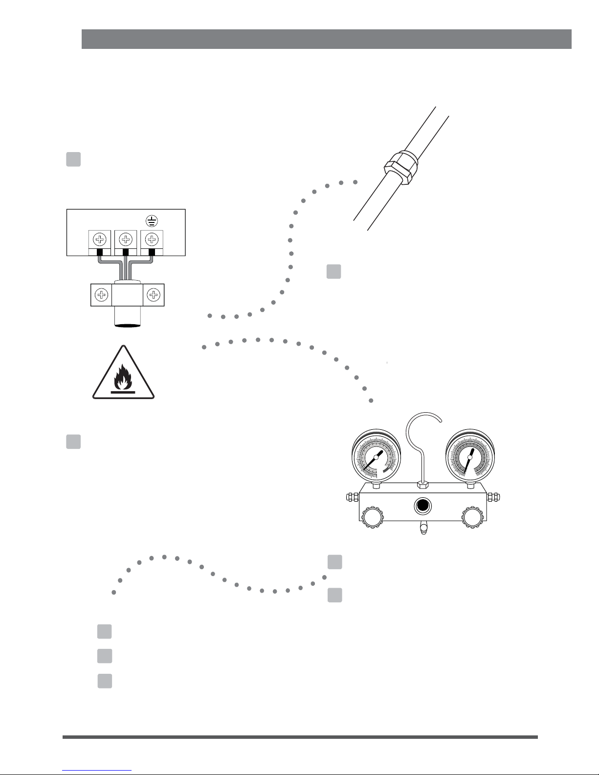
Ca ut io n: R is k of f ire
(for R32
B. Refrigerant Piping Connection Instructions........18
Service Info..............................28
14
Installation Manual
Installation Manual
Page 4
Page 4
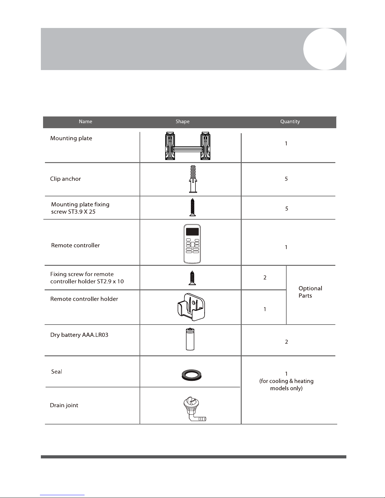
Accessories
1
The air conditioning system comes with the following accessories. Use all of the installation parts and accessories to
install the air conditioner. Improper installation may result in water leakage, electrical shock and fire, or cause the
equipment to fail.
Page 5
Page 5
Safety Precautions
2
Read Safety Precautions Before Installation
potential damage or injuries is classified as either a WARNING or CAUTION.
WARNING
• Carefully read the Safety Precautions before installation.
•
• Only trained and certified technicians should install, repair and service this air conditioning unit.
Improper installation may result in electrical shock, short circuit, leaks, fire or other damage to the equipment and
personal property.
• Strictly follow the installation instructions set forth in this manual.
Improper installation may result in electrical shock, short circuit, leaks, fire or other damage to the equipment.
toxic and flammable and poses a serious health and safety risk.
Note about Fluorinated Gasses
1. This air-conditioning unit contains fluorinated gasses. For specific information on the type of gas and the amount,
please refer to the relevant label on the unit itself.
2. Installation, service, maintenance and repair of this unit must be performed by a certified technician.
3. Product uninstallation and recycling must be performed by a certified technician.
4. If the system has a leak-detection system installed, it must be checked for leaks at least every 12 months.
5. When the unit is checked for leaks, proper record-keeping of all checks is strongly recommended.
national regulations.
Failure to observe a caution may result in injury or equipment damage.
WARNING
CAUTION
locate it accordingly. Failure to do so could cause the equipment to fail.
• After installation, ensure there are no refrigerant leaks and that the unit is operating properly. Refrigerant is
both
Incorrect installation due to ignoring instructions can cause serious damage or injury. The seriousness of
Failure to observe a warning may result in death. The appliance must be installed in accordance with
conditioning units is highly recommended.
In certain functional environments, such as server rooms, etc., the use of specially designed air-
NOTE: Requirements for units using R32 Refrigerant.
Do not accelerate the defrosting process or to clean, other than those
recommended by the manufacturer.
The system should not be installed in areas with ignition sources
(for example: open flames,an operating gas appliance or an operating
electric heater)
Do not pierce or burn.
The system should be installed where the room size corresponds to specific
operation.
Be aware that refrigerants may not contain an odour.
Page 6
Page 6
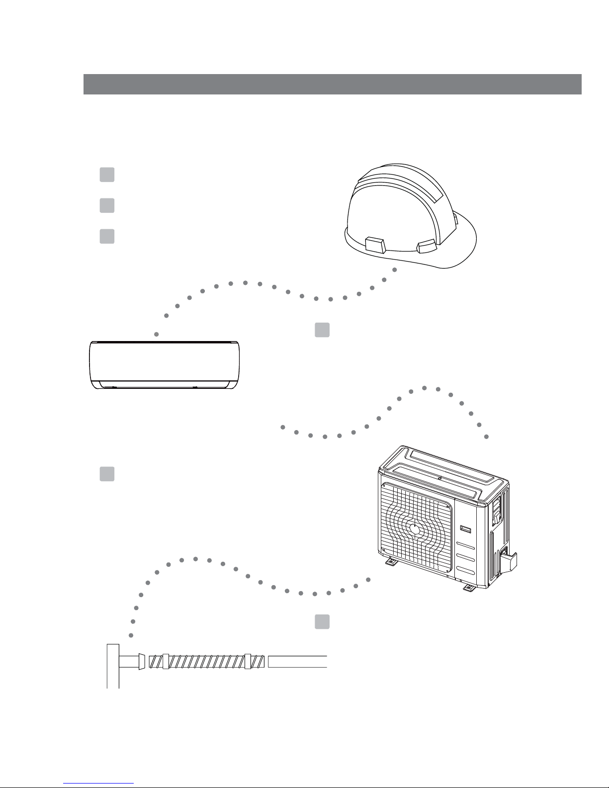
Installation Overview
3
Unit Installation
Overview
INSTALLATION ORDER
Page 7
Page 7
Indoor Unit Installation
4
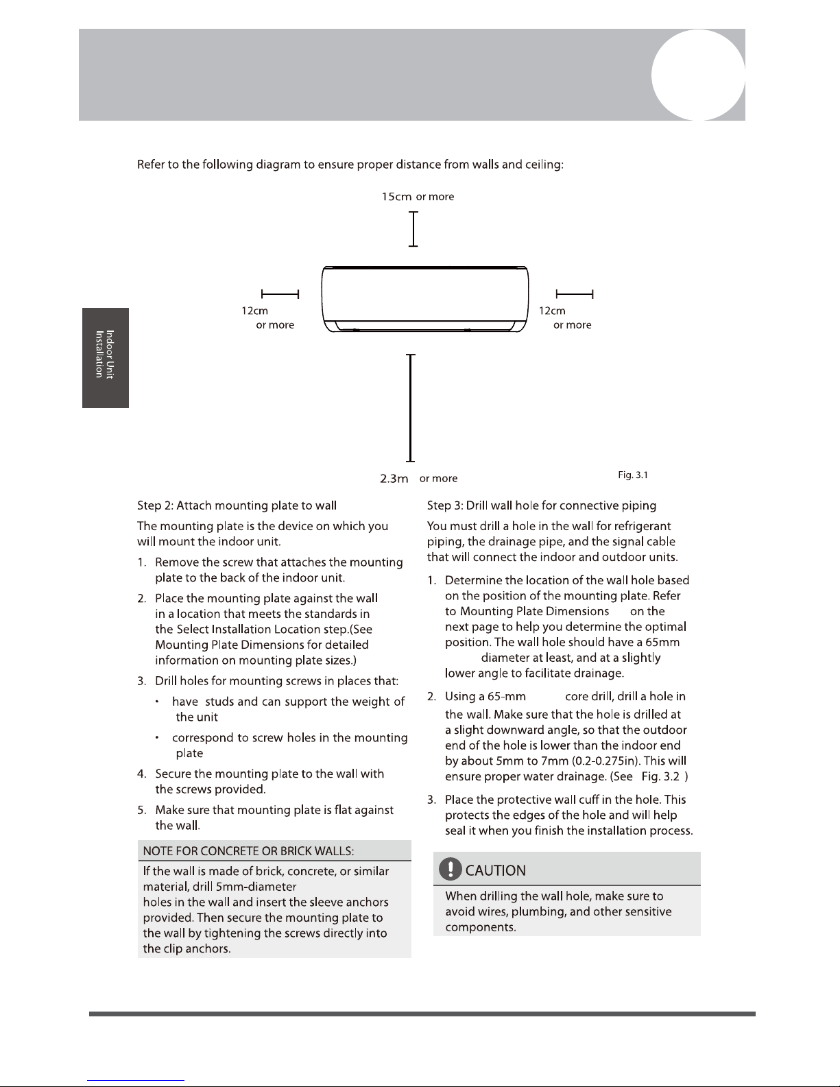
Safety Precautions
WARNING
• Securely install the indoor unit on a structure that
can sustain its weight. If the structure is too weak
the unit may fall causing personal injury, unit and
property damage or death.
CAUTION
Indoor Unit
Installation
• Install the indoor and outdoor units, cables and
to prevent static or image distortion. Depending
• If the indoor unit is installed on a metal part of the
building, it must be electrically grounded.
on the appliances, a 1m distance may not be
wires at least 1m from televisions or radios
Page 8
Page 8
Indoor Unit Installation
4
Page 9
Page 9
Indoor Unit Installation
4
For MSMBAU-09HRFN1-QRD0GW:
For MSMBBU-12HRFN1-QRD0GW:
For MSMBCU-18HRFN1-QRD0GW:
For MSMBDU-24HRFN1-QRD0GW:
Page 10
Page 10
Indoor Unit Installation
4
Page 11
Page 11
Outdoor Unit Installation
5
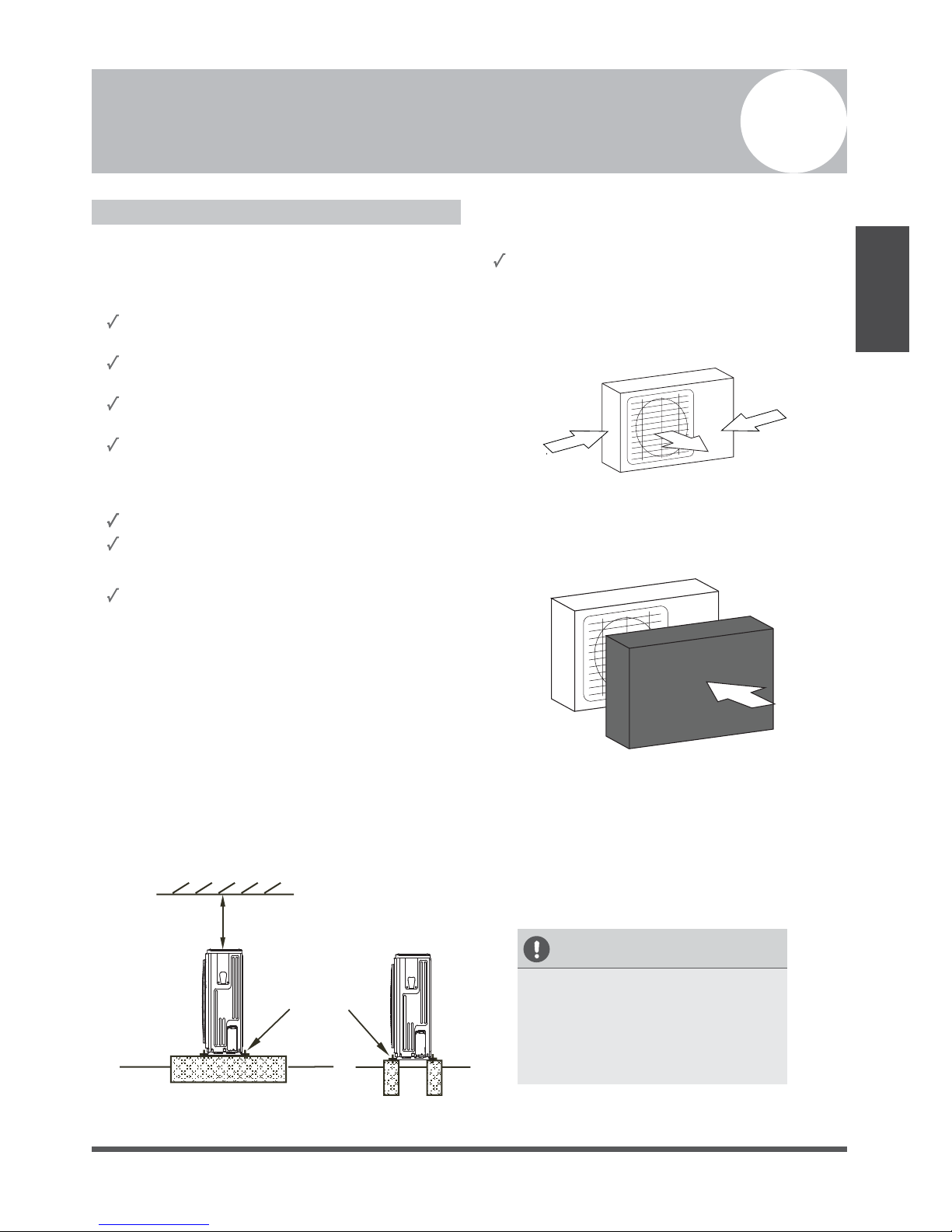
Outdoor Unit Installation Instructions
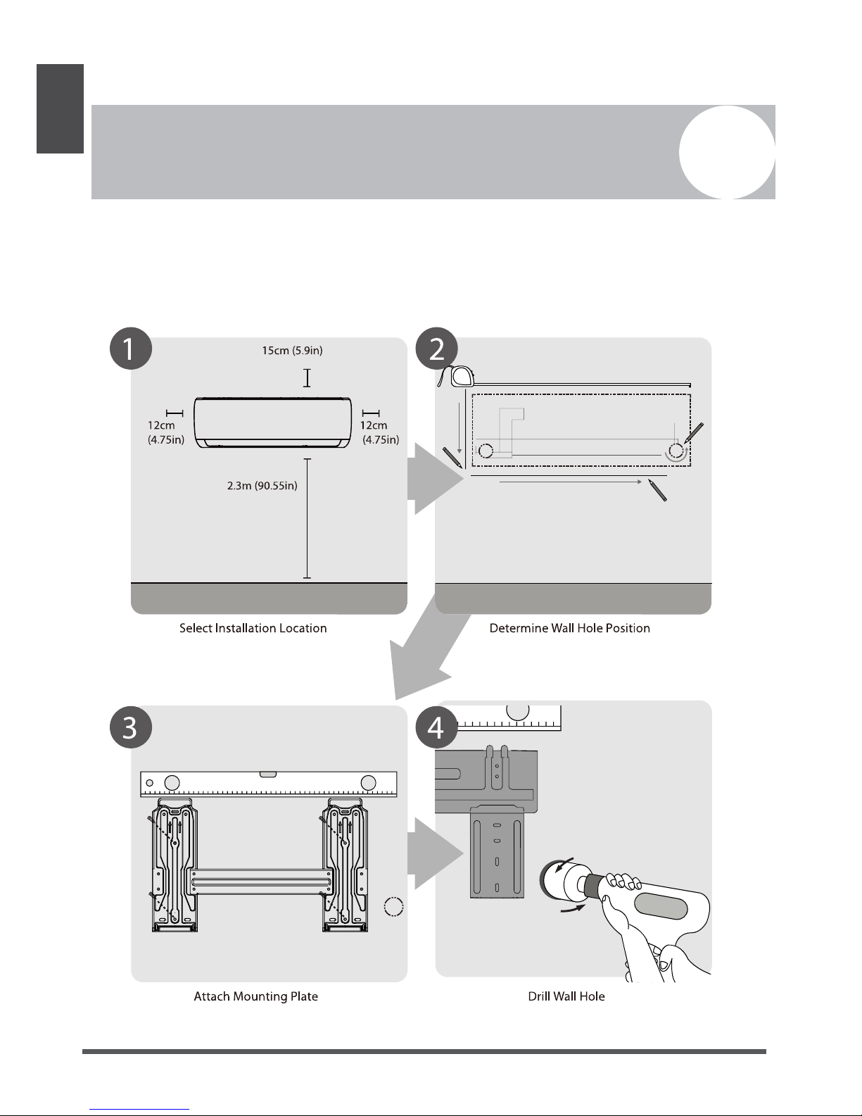
Step 1: Select installation location.
The outdoor unit should be installed in the location that
meets the following requirements:
Place the outdoor unit as close to the indoor unit as
possible.
Ensure that there is enough room for installation and
maintenance.
The air inlet and outlet must not be obstructed or
exposed to strong wind.
Ensure the location of the unit will not be subject to
snowdrifts, accumulation of leaves or other seasonal
debris. If possible, provide an awning for the unit.
Ensure the awning does not obstruct airflow.
The installation area must be dry and well ventilated.
There must be enough room to install the connecting
pipes and cables and to access them for maintenance.
The pipe length between the outdoor and indoor unit
may not exceed the maximum allowable pipe length.
Strong wind
Strong wind
Strong wind
Fig. 5.1
Step 2: Install outdoor unit.
Fix the outdoor unit with anchor bolts (M10)
Fix with bolts
CAUTION
• Be sure to remove any obstacles that
may block air circulation.
• Make sure you refer to Length
Specifications to ensure there is
enough room for installation and
maintenance.
Fig. 5.3
Outdoor Unit
Installation
>60cm
Fig. 5.2
If the location is exposed to strong winds the unit
must be placed against the wall to shelter it from
the wind.
Page 12
Page 12
Outdoor Unit
Installation
Since the gravity center of the unit is not at its physical center, so please be careful when lifting it with a sling.
Never hold the inlet of the outdoor unit to prevent it from deforming.
Do not touch the fan with hands or other objects.
Do not lean it more than 45, and do not lay it sidelong.
Make concrete foundation according to the specifications of the outdoor units.
Fasten the feet of this unit with bolts firmly to prevent it from collapsing in case of earthquake or strong wind.
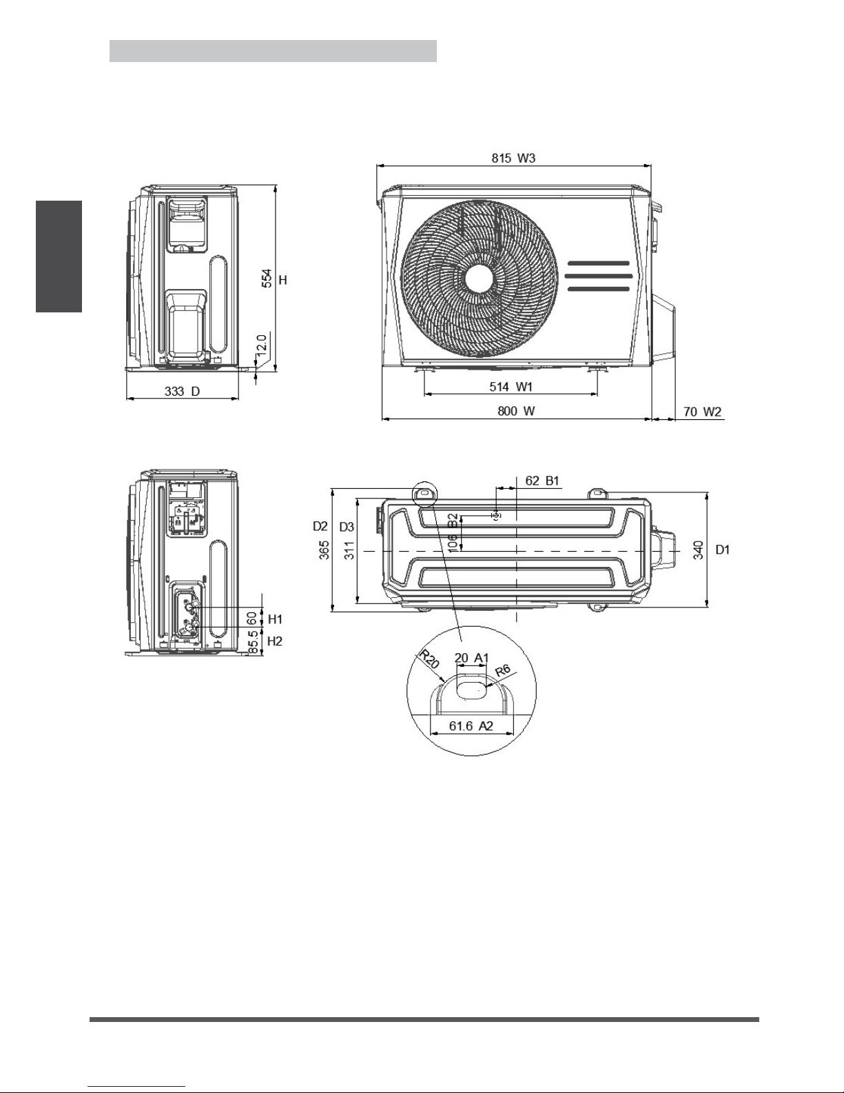
Outdoor Unit Installation Instructions
For MOB01-09HFN1-QRD0GW, MOB01-12HFN1-QRD0GW, MOB01-18HFN1-QRD0GW,
Page 13

8 0 0 W
5 1 4 W 1
815 W3
333 D
70 W2
H
H1
H2
D1
D2
D3
62 B1
20 A1
61.6 A2
For MOB02-18HFN1-QRD0GW
Page 13
Outdoor Unit Installation Instructions
Page 14

For MOCA02-24HFN1-QRD0GW,
Page 14
Outdoor Unit Installation Instructions
Page 15

NOTE: The minimum distance between the outdoor
unit and walls described in the installation guide does
not apply to airtight rooms. Be sure to keep the unit
unobstructed in at least two of the three directions (M,
N, P) (See Fig. 5.10)
Fig. 5.10
Drain Joint Installation
Before bolting the outdoor unit in place, you must install
the drain joint at the bottom of the unit. (See Fig. 5.11)
1. Fit the rubber seal on the end of the drain joint that
will connect to the outdoor unit.
2. Insert the drain joint into the hole in the base pan of
the unit.
3. Rotate the drain joint 90° until it clicks in place
facing the front of the unit.
4. Connect a drain hose extension (not included) to
the drain joint to redirect water from the unit during
heating mode.
NOTE: Make sure the water drains to a safe location
where it will not cause water damage or a slipping
hazard.
Seal
Drain joint
(A) (B)
Base pan hole of
outdoor unit
Seal
Fig. 5.11
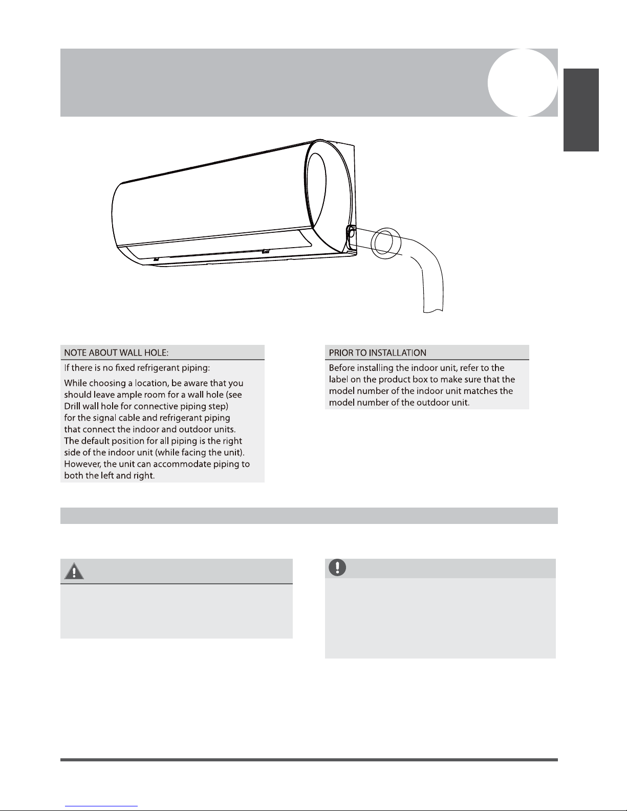
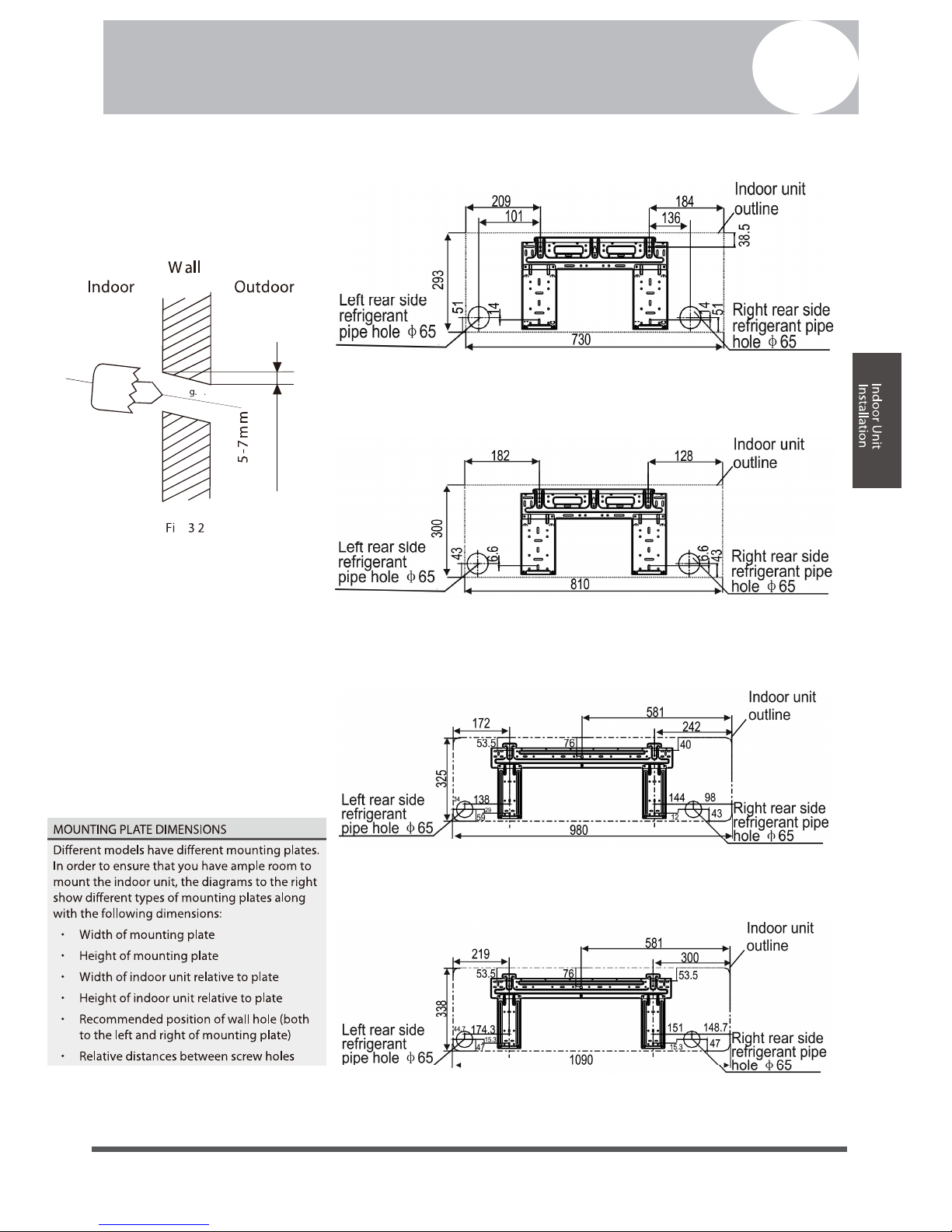
Notes On Drilling Hole In Wall
You must drill a hole in the wall for the refrigerant piping,
and the signal cable that will connect the indoor and
outdoor units.
1. Determine the location of the wall hole based on the
location of the outdoor unit.
2.
NOTE: When drilling the wall hole, make sure
to avoid wires, plumbing, and other sensitive
components.
3. Place the protective wall cuff in the hole. This
protects the edges of the hole and will help seal it
when you finish the installation process.
Outdoor Unit
Installation
Using a 65-mm core drill, drill a hole in the wall.
Page 15
evoba
mc06
60cm
on right
30cm
on left
200cm
in front
30cm
Page 16

Drainpipe Installation
6
Page 16
Page 17

Refrigerant Piping Connection
7
WARNING
• All field piping must be completed by a licensed
technician and must comply with the local and
national regulations.
• When the air conditioner is installed in a small
room, measures must be taken to prevent the
refrigerant concentration in the room from
exceeding the safety limit in the event of
refrigerant leakage. If the refrigerant leaks and
its concentration exceeds its proper limit, hazards
due to lack of oxygen may result.
• When installing the refrigeration system, ensure
that air, dust, moisture or foreign substances do
not enter the refrigerant circuit. Contamination
in the system may cause poor operating capacity,
high pressure in the refrigeration cycle, explosion
or injury.
• Ventilate the area immediately if there is
refrigerant leakage during the installation. Leaked
refrigerant gas is both toxic and flammable.
Ensure there is no refrigerant leakage after
completing the installation work.
Notes On Pipe Length and Elevation
Ensure that the length of the refrigerant pipe, the number
of bends, and the drop height between the indoor and
outdoor units meets the requirements shown in Table 7.1:
Table 7.1: The Maximum Length And Drop Height
Maximum drop
height
Refrigerant Piping
Connection
Based on Models. (Unit: meters)
09 25
CAUTION
An angle of more than 10° may cause malfunction.
• DO NOT install the connecting pipe until both
indoor and outdoor units have been installed.
• Insulate both the gas and liquid piping to prevent
water leakage.
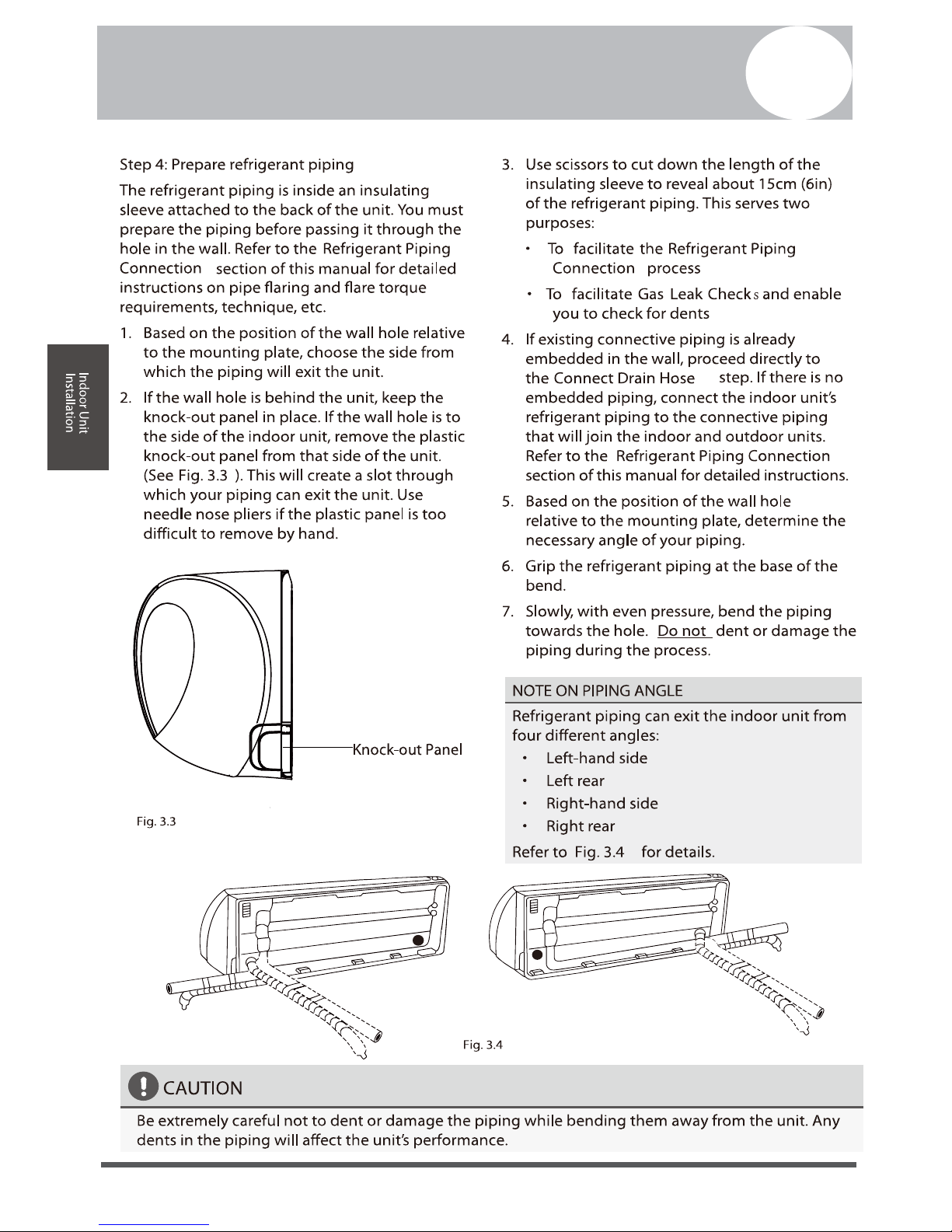
Refrigerant Piping Connection Instructions
Step1: Cut pipes
When preparing refrigerant pipes, take extra care
to cut and flare them properly. This will ensure
efficient operation and minimize the need for future
maintenance.
1. Measure the distance between the indoor and
outdoor units.
2. Using a pipe cutter, cut the pipe a little longer than
the measured distance.
Model Length of
piping
Page 17
12 25 10
18 30 20
24 25
Page 18

CAUTION
DO NOT deform pipe while cutting. Be extra careful not
to damage, dent, or deform the pipe while cutting. This
will drastically reduce the heating efficiency of the unit.
1. Make sure that the pipe is cut at a perfect 90°
angle. Refer to Fig. 7.2 for examples of bad cuts
Oblique
Rough
Warped
90°
Fig. 7.2
Step 2: Remove burrs.
1. Hold the pipe at a downward angle to prevent
burrs from falling into the pipe.
2. Using a reamer or deburring tool, remove all burrs
from the cut section of the pipe.
Pipe
Reamer
1. After removing burrs from cut pipe, seal the ends
with PVC tape to prevent foreign materials from
entering the pipe.
2. Sheath the pipe with insulating material.
3. Place flare nuts on both ends of pipe. Make sure
they are facing in the right direction, because you
can’t put them on or change their direction after
flaring. See Fig. 7.4
Flare nut
Copper pipe
Fig. 7.4
4. Remove PVC tape from ends of pipe when ready to
perform flaring work.
5. Clamp flare form on the end of the pipe. The end
of the pipe must extend beyond the flare form.
Flare form
Pipe
Fig. 7.5
Refrigerant Piping
Connection
piping connection. They must be completely
removed.
Point down
Burrs can affect the gas-tight seal of refrigerant
Refrigerant Piping Connection
7
Page 18
Step 3: Flare pipe ends
Proper flaring is essential to achieve an
Fig. 7.3
Page 19

6. Place flaring tool onto the form.
7. Turn the handle of the flaring tool clockwise until
the pipe is fully flared. Flare the pipe in accordance
with the dimensions shown in table 7-3.
Table 7.3: PIPING EXTENSION BEYOND FLARE FORM
Pipe
gauge
Tightening
torque
Flare dimension (A) Flare shape
Min. Max .
14.2-17.2 N.m
(144-176 kgf.cm)
R0.4~0.8
45
°
±
2
90
°
±
4
A
Fig. 7.6
32.7-39.9 N.m
(333-407 kgf.cm)
49.5-60.3 N.m
(504-616 kgf.cm)
61.8-75.4 N.m
(630-770 kgf.cm)
97.2-118.6 N.m
(990-1210 kgf.
cm)
8. Remove the flaring tool and flare form, then inspect
the end of the pipe for cracks and even flaring.
Step 4: Connect pipes
Connect the copper pipes to the indoor unit first, then
connect it to the outdoor unit. You should first connect the
low-pressure pipe, then the high-pressure pipe.
1. When connecting the flare nuts, apply a thin coat
of refrigeration oil to the flared ends of the pipes.
2. Align the center of the two pipes that you will
connect.
Indoor unit tubing
Flare nut
Pipe
Fig. 7.7
3. Tighten the flare nut as tightly as possible by hand.
4. Using a spanner, grip the nut on the unit tubing.
5. While firmly gripping the nut, use a torque wrench
to tighten the flare nut according to the torque
values in table 7-.3.
NOTE: Use both a spanner and a torque wrench when
connecting or disconnecting pipes to/from the unit.
Fig. 7.8
CAUTION
Check to make sure there is no refrigerant leak after
completing the installation work. If there is a refrigerant
leak, ventilate the area immediately and evacuate
the system (refer to the Air Evacuation section of this
manual).
Refrigerant Piping
Connection
109.5-133.7 N.m
(1117-1364 kgf.
cm)
(Unit: mm)
Page 19
8.3 8.3
12.4 12.4
15.4 15.8
18.6 19
22.9 23.3
27 27.3
Page 20

8
Safety Precautions
WARNING
• Be sure to disconnect the power supply before
working on the unit.
• All electrical wiring must be done according to
local and national regulations.
• Electrical wiring must be done by a qualified
technician. Improper connections may cause
electrical malfunction, injury and fire.
• An independent circuit and single outlet must
• Connect the power cable to the terminals and
fasten it with a clamp. An insecure connection
may cause fire.
• Make sure that all wiring is done correctly and the
control board cover is properly installed. Failure
to do so can cause overheating at the connection
points, fire, and electrical shock.
• Ensure that main supply connection is made
through a switch that disconnects all poles, with
CAUTION
• Connect the outdoor wires before connecting the
indoor wires.
• Make sure you ground the unit. The grounding
wire should be away from gas pipes, water pipes,
lightning rods, telephone or other grounding
wires. Improper grounding may cause electrical
shock.
• DO NOT connect the unit with the power source
until all wiring and piping is completed.
• Make sure that you do not cross your electrical
wiring with your signal wiring, as this can cause
distortion and interference.
Follow these instructions to prevent distortion when the
compressor starts:
• The unit must be connected to the main outlet.
Normally, the power supply must have a low output
impedance of 32 ohms.
• No other equipment should be connected to the
same power circuit.
• The unit’s power information can be found on the
Outdoor Unit Wiring
WARNING
Before performing any electrical or wiring work, turn off
the main power to the system.
1. Prepare the cable for connection
Rated Current of
Appliance (A)
Nominal Cross-Sectional
Area (mm²)
6 0.75
6 - 10 1
10 - 16 1.5
16 - 25 2.5
25- 32 4
32 - 45 6
Wiring
contact gap of a least 3mm.
Wiring
be used for this unit. If the
electrical circuit capacity is not enough or there
is a defect in the electrical work, it can lead to
shock, fire, unit and property damage.
Page 20
NOTE: The fuse is made of ceramic.
rating sticker on the product.
Page 21

b. Using wire strippers, strip the rubber jacket from
both ends of signal cable to reveal about 15cm
c. Strip the insulation from the ends of the wires.
d. Using a wire crimper, crimp u-lugs on the ends of
the wires.
NOTE: While connecting the wires, please strictly follow
the wiring diagram (found inside the electrical box cover).
2. Remove the electric cover of the outdoor unit.
If there is no cover on the outdoor unit, disassemble
the bolts from the maintenance board and remove the
protection board. (See Fig. 8.1, 8.2)
Cover
Screw
Fig. 8.1
3. Connect the u-lugs to the terminals
4. Clamp down the cable with designated cable clamp.
5. Insulate unused wires with electrical tape. Keep them
away from any electrical or metal parts.
6. Reinstall the cover of the electric control box.
Indoor Unit Wiring
1. Prepare the cable for connection
a. Using wire strippers, strip the rubber jacket from
both ends of signal cable to reveal about 15cm
b. Strip the insulation from the ends of the wires.
c. Using wire crimper, crimp the u-lugs to the ends of
the wires.
2. Open the front panel of the indoor unit. Using a
screwdriver, remove the cover of the electric control box
on your indoor unit.
3. Thread the power cable and the signal cable through
the wire outlet.
4. Connect the u-lugs to the terminals.
Connective wiring diagram
Wiring diagram
CAUTION
• While connecting the wires, please strictly follow
the wiring diagram.
• The refrigerant circuit can become very hot. Keep
the interconnection cable away from the copper
tube.
5. Clamp down cable with the designated cable clamp to
secure it in place. The cable should not be loose, and
6. Reinstall the electric box cover and the front panel of
the indoor unit.
Wiring
Fig. 8.4
of the wires inside.
of the wires inside.
should not pull on the u-lugs.
Terminal block
Wire cover
Screw
Cable clamp
Match the wire colours/labels with the labels on the
terminal block, and firmly screw the u-lug of each
wire to its corresponding terminal. Refer to the Serial
Number and Wiring Diagram located on the cover of
the electric control box.
Match the wire colours/labels with the labels on the
terminal block, and firmly screw the u-lug of each wire
to its corresponding terminal.
Page 21
Page 22

Power Specifications
POWER
PHASE 1 Phase 1 Phase 1 Phase 1 Phase
FREQUENCY
AND VOLT
CIRCUIT BREAKER/
FUSE(A)
Wiring
FREQUENCY
AND VOLT
CIRCUIT BREAKER/
FUSE(A)
POWER
Indoor Power Supply Specifications
Outdoor Inverter Power Supply Specifications
MODEL 09 12 18 24
MODEL 09 12 18 24
220-240V 220-240V 220-240V 220-240V
16A 16A 16A 20A
POWER FROM OUTDOOR UNIT
PHASE 1 Phase 1 Phase 1 Phase 1 Phase
Wiring Diagrams
220-240V 220-240V 220-240V 220-240V
Page 22
Page 23

Wiring Diagrams
Page 23
S
ROOM TEMPERATURE SENSOR
PIPE TEMPERATURE SENSOR
SWING MOTOR1
5
M
CN5
INDOOR UNIT
OUTDOOR UNIT
YELLOW
JX1
Y/G
WHI ET
RED
CN6_1
CN12_1
CN6_2
CN12_2
M
CN14
5(10)
SWING MOTOR2
OPTIONAL
MICRO SWITCH
PLASMA
2
CN43
CN44
OPTIONAL
IN FAN
M
5
CN4
N
CN11(CN1)
CN16
CN8
CN9
2
2
RY1
L-OUT
L-IN
P_1
W
2(N)
S
BLUE(BLACK)
ION
OPTIONAL
Y/G
HEATER
OPTIONAL
NOTE: If used as MONO unit, for the standby control needs, the cross section area of cable connected to W, 1(L)
must be sufficient for the maximum system current. The maximum system current is equal to the sum of indoor unit
and outdoor unit rated current. If used as MULTI unit, W on the terminal block does not need to be connected.
OPTIONAL
DISPLAY BOARD
CN10A
8(7)
(CN10)
Wire Controller
2
OPTIONAL
MULTI-FUCTION CONTROL BOX
OPTIONAL
1(L)
OPTIONAL
CN2(CN101)
CN3(CN301)
2
CN9
CN602
DISPLAY BOARD
CN1(OR CN201)
CN3(OR CN301)
CN2(OR CN101)
8
Wire Controller
WiFi Controller
4
4
4
8
5
5
5
OPTIONAL
WiFi Controller
Page 24

9
Pressure Test Instructions
Systems are pressure tested to ensure they are:
Pressure testing is hazardous and should be carried out carefully:
Nitrogen and regulation
Dry (oxygen free) nitrogen (OFN) is used to achieve the pressures required for the
pressure tests because it is inert. You must never use oxygen for pressure testing pure oxygen at high pressure reacts violently with oil and will explode.
Using the nitrogen regulator
to the pressure required.
Do not use a regulator with an
output pressure much higher
The pressure tests
Increase the pressure to approximately 5 bar g and check for leaks using leak
detection spray at this pressure initially – many leaks will be identified at this
pressure so you will not waste nitrogen and time. It is also safer to find leaks at a
lower pressure than the final test pressures.
Increase the pressure slowly to the strength test pressure and hold it for 15
minutes. Under the Pressure Equipment Regulation this strength test might need
to be witnessed by a notified body.
Safe – for this test a pressure above the system’s maximum allowable
pressure (PSi) is used
Leak tight – this test is at PSi.
The nitrogen used for pressure testing is an asphyxiant, so the area around
the system should be well-ventilated
High pressures are used, so all non-essential personal should be evacuated
from the area
Anyone carrying out the pressure testing should wear safety goggles.
2. Open the cylinder valve
3. Slowly open the regulator
Page 24
1. Ensure the regulator is
closed (wound fully anti
clockwise)
Page 25

Air Evacuation
9
Safety Precautions
CAUTION
than -0.1MPa and an air discharge capacity above
40L/min.
• The outdoor unit does not need vacuuming. DO
NOT open the outdoor unit’s gas and liquid stop
valves.
or below after 2 hours. If after three hours of
operation and the gauge reading is still above
-0.1MPa, check if there is a gas leak or water inside
the pipe. If there is no leakage, perform another
evacuation for 1 or 2 hours.
• DO NOT use refrigerant gas to evacuate the
system.
Evacuation Instructions
Before using manifold gauge and vacuum pump, read their
operation manuals to familiarize yourself with how to use
them properly.
Manifold Gauge
Compound gauge
-76cmHg
Low pressure valve
High pressure valve
Charge hose
Charge hose
Vacuum pump
Pressure gauge
Low pressure valve
Fig. 9.1
1. Connect the charge hose of the manifold gauge to
service port on the outdoor unit’s low pressure valve.
2. Connect another charge hose from the manifold gauge
to the vacuum pump.
3. Open the Low Pressure side of the manifold gauge.
Keep the High Pressure side closed.
4. Turn on the vacuum pump to evacuate the system.
5. Run the vacuum for at least 15 minutes, or until the
NOTE: If there is no change in system pressure, unscrew
the cap from the packed valve (high pressure valve). If
there is a change in system pressure, there may be a gas
leak.
8. Insert hexagonal wrench into the packed valve (high
pressure valve) and open the valve by turning the
wrench in a 1/4 counterclockwise turn. Listen for gas to
exit the system, then close the valve after 5 seconds.
Flare nut
Cap
Valve body
Valve stem
Fig. 9.2
9. Watch the Pressure Gauge for one minute to make sure
that there is no change in pressure. The Pressure Gauge
should read slightly higher than atmospheric pressure.
10. Remove the charge hose from the service port.
11. Using hexagonal wrench, fully open both the high
pressure and low pressure valves.
OPEN VALVE STEMS GENTLY
When opening valve stems, turn the hexagonal wrench
until it hits against the stopper. DO NOT try to force the
valve to open further.
12. Tighten valve caps by hand, then tighten it using the
proper tool.
Air Evacuation
turn off the vacuum pump.
change in system pressure.
7. Wait for 5 minutes, then check that there has been no
Gauge reads -76cmHG (-1x10⁵Pa).
6. Close the Low Pressure side of the manifold gauge, and
• Use a vacuum pump with a gauge reading lower
• Ensure that the Compound Meter reads -0.1MPa
Page 25
Page 26

CAUTION
• Refrigerant charging must be performed after wiring, vacuuming and the leak test.
• DO NOT exceed the maximum allowable quantity of refrigerant or overcharge the system. Doing so can damage
or impact the unit’s function.
• Charging with unsuitable substances may cause explosions or accidents. Ensure that the appropriate refrigerant is
used.
• Refrigerant containers must be opened slowly. Always use protective gear when charging the system.
Air Evacuation
• DO NOT mix refrigerant types.
Refrigerant may only be charged after performed the vacuum drying process.
Always use gloves and glasses to protect your hands and eyes during the charge work.
Use electronic scale or fluid infusion apparatus to weight refrigerant to be recharged. Be sure to avoid
extra refrigerant charged, it may cause liquid hammer of the compressor or protections.
Use supplementing flexible pipe to connect refrigerant cylinder, pressure gauge and outdoor unit. And
The refrigerant should be charged in liquid state. Before recharging, The air in the flexible pipe and
manifold gauge should be exhausted.
After finished refrigerant recharge process, check whether there is refrigerant leakage at the connection
joint part.(Using gas leakage detector or soap water to detect).
Moooo
Min. Max .
Note :
Some systems require additional charging depending on pipe lengths
The additional refrigerant to be charged can be calculated using the following Table below.
9
Refrigerant Additional Charge
Page 26
5 Meter
5 Meter
R32 Additional Refrigerant Charge
R410a Additional Refrigerant Charge
Model Shipment Charge Charged To Additional Charge
18 2 Kg
30 g/m
24 2.4 Kg
30 g/m
09 1.35 Kg 5 Meter 15 g/m
12 1.5 Kg 5 Meter 30 g/m
Page 27

Test Run
Before Test Run
A test run must be performed after the entire system has
been completely installed. Confirm the following points
before performing the test:
a) The indoor and outdoor units are properly installed.
b) Piping and wiring are properly connected.
c) Ensure that there are no obstacles near the inlet
and outlet of the unit that might cause poor
performance or product malfunction.
d) The refrigeration system does not leak.
e) The drainage system is unimpeded and draining to
a safe location.
f) The heating insulation is properly installed.
g) The grounding wires are properly connected.
h) The length of the piping and the added refrigerant
stow capacity have been recorded.
i) The power voltage is the correct voltage for the air
conditioner.
CAUTION
Failure to perform the test run may result in unit
damage, property damage or personal injury.
Test Run Instructions
1. Open both the liquid and gas stop valves.
2. Turn on the main power switch and allow the unit to
warm up.
3. Set the air conditioner to COOL mode.
4. For the Indoor Unit
a. Ensure the remote control and its buttons work
properly.
b. Ensure the louvers move properly and can be
changed using the remote control.
c. Double check to see if the room temperature is
being registered correctly.
d. Ensure the indicators on the remote control and the
display panel on the indoor unit work properly.
e. Ensure the manual buttons on the indoor unit
works properly.
f. Check to see that the drainage system is
unimpeded and draining smoothly.
g. Ensure there is no vibration or abnormal noise
during operation.
5. For the Outdoor Unit
a. Check to see if the refrigeration system is leaking.
b. Make sure there is no vibration or abnormal noise
during operation.
c. Ensure the wind, noise, and water generated by the
unit do not disturb your neighbors or pose a safety
hazard.
6. Drainage Test
a. Ensure the drainpipe flows smoothly. New buildings
should perform this test before finishing the ceiling.
b. Remove the test cover. Add 2,000ml of water to the
tank through the attached tube.
c. Turn on the main power switch and run the air
conditioner in COOL mode.
d. Listen to the sound of the drain pump to see if it
makes any unusual noises.
e. Check to see that the water is discharged. It may
take up to one minute before the unit begins to
drain depending on the drainpipe.
f. Make sure that there are no leaks in any of the
piping.
g. Stop the air conditioner. Turn off the main power
switch and reinstall the test cover.
NOTE: If the unit malfunctions or does not operate
according to your expectations, please refer to the
Troubleshooting section of the Owner’s Manual before
calling customer service.
Test Run
10
Page 27
Page 28

Information
Servicing
1. Checks to the area
3. General work area
4. Checking for presence of refrigerant
5. Presence of fire extinguisher
If any hot work is to be conducted on the refrigeration equipment or any associated parts, appropriate
fire extinguishing equipment shall be available to hand. Have a dry power or CO2 fire extinguisher
adjacent to the charging area.
7. Ventilated area
Ensure that the area is in the open or that it it adequately ventilated before breaking into the system
or conducting any hot work. A degree of ventilation shall continue during the period that the work is
carried out. The ventilation should safely disperse any released refrigerant and preferably expel it
externally into the atmosphere.
2. Work procedure
All mintenance staff and others working in the local area shall be instructed on the nature of work
being carried out. work in confined sapces shall be avoided. The area around the work space shall
be sectioned off. Ensure that the conditions within the area have been made safe by control of
flammable material.
Prior to beginning work on systems containing flammable refrigerants, safety checks are necessary
to ensure that the risk of ignition is minimised. For repair to the refrigerating system, the following
precautions shall be complied with prior to conducting work on the system.
Works shall be undertaken under a controlled procedure so as to minimise the risk of a
flammable gas or vapour being present while the work is being performed.
The area shall be checked with an appropriate refrigerant detector prior to and during work,
to ensure the technician is aware of potentially flammable atmospheres. Ensure that the leak
detection equipment being used is suitable for use with flammable refrigerants, i.e. no sparking,
adequately sealed or intrinsically safe.
,
,
8. Checks to the refrigeration equipment
Where electrical components are being changed, they shall be fit for the purpose and to the correct
specification. At all times the manufacturers maintenance and service guidelines shall be followed.
If in doubt consult the manufacturers technical department for assistance. The following checks shall
be applied to installations using flammable refrigerants:
6. No ignition sources
No person carrying out work in relation to a refrigeration system which involves exposing any pipe
work that contains or has contained flammable refrigerant shall use any sources of ignition in such a
manner that it may lead to the risk of fire or explosion. All possible ignition sources, including cigarette
smoking, should be kept sufficiently far away from the site of installation, repairing, removing and
disposal, during which flammable refrigerant can possibly be accidentally released to the surrounding
space. Prior to work taking place, the area around the equipment is to be surveyed to make sure that
there are
no flammable hazards or ignition risks. NO SMOKING signs shall be displayed.
Servicing Info
Page 28
(Required for the units adopt R32 Refrigerant only)
11
Page 29

,
9. Checks to electrical devices
10. Repairs to sealed components
the charge size is in accordance with the room size within which the refrigerant containing
parts are installed;
the ventilation machinery and outlets are operating adequately and are not obstructed;
if an indirect refrigerating circuit is being used, the secondary circuits shall be checked
for the presence of refrigerant; marking to the equipment continues to be visible and
legible.
marking and signs that are illegible shall be corrected;
refrigeration pipe or components are installed in a position where they are unlikely to be
exposed to any substance which may corrode refrigerant containing components, unless
the components are constructed of materials which are inherently resistant to being
corroded or are suitably protected against being so corroded.
10.1 During repairs to sealed components, all electrical supplies shall be disconnected from the
equipment being worked upon prior to any removal of sealed covers, etc. If it is absolutely
necessary to have an electrical supply to equipment during servicing, then a permanently
operating form of leak detection shall be located at the most critical point to warn of a
potentially hazardous situation.
10.2 Particular attention shall be paid to the following to ensure that by working on electrical
components, the casing is not altered in such a way that the level of protection is affected.
This shall include damage to cables, excessive number of connections, terminals not made
to original specification, damage to seals, incorrect fitting of glands, etc.
Ensure that apparatus is mounted securely.
Ensure that seals or sealing materials have not degraded such that they no longer serve
the purpose of preventing the ingress of flammable atmospheres. Replacement parts shall
be in accordance with the manufacturer s specifications.
NOTE: The use of silicon sealant may inhibit the effectiveness of some types of leak detection
equipment. Instrinsically safe components do not have to be isolated prior to working on them.
Information
Servicing
Repair and maintenance to electrical components shall include initial safety checks and
component inspection procedures. If a fault exists that could compromise safety, then no
electrical supply shall be connected to the circuit until it is satisfactorily dealt with. If the fault
cannot be corrected immediately but it is necessary to continue operation, and adequate
temporary solution shall be used. This shall be reported to the owner of the equipment so all
parties are advised.
Initial safety checks shall include:
that capacitors are discharged: this shall be done in a safe manner to avoid possibility of
sparking
that there no live electrical components and wiring are exposed while charging, recovering
or purging the system;
that there is continuity of earth bonding.
Page 29
Page 30

11. Repair to intrinsically safe components
Do not apply any permanent inductive or capacitance loads to the circuit without ensuring
that this will not exceed the permissible voltage and current permitted for the equipment in
use. Intrinscially safe components are the only types that can be worked on while live in the
presence of a flammable atmosphere. The test apparatus shall be at the correct rating.
Replace components only with parts specified by the manufacturer. Other parts may result
in the ignition of refrigerant in the atmosphere from a leak.
12. Cabling
Check that cabling will not be subject to wear, corrosion, excessive pressure, vibration, sharp
edges or any other adverse environmental effects. The check shall also take into account the
effects of aging or continual vibration from sources such as compressors or fans.
13. Detection of flammable refrigerants
Under no circumstances shall potential sources of ignition be used in the searching for or
detection of refrigerant leaks. A halide torch(or any other detector using a naked flame)
shall not be used.
Information
Servicing
14. Leak detection methods
The following leak detection methods are deemed acceptable for systems containing flammable
refrigerants. Electronic leak detectors shall be used to detect flammable refrigerants, but the
sensitivity may not be adequate, or may need re-calibration.(Detection equipment shall be
calibrated in a refrigerant-free area.) Ensure that the detector is not a potential source of ignition
and is suitable for the refrigerant. Leak detection equipment shall be set at a percentage of the
LFL of the refrigerant and shall be calibrated to the refrigerant employed and the appropriate
percentage of gas (25% maximum) is confirmed. Leak detection fluids are suitable for use with
most refrigerants but the use of detergents containing chlorine shall be avoided as the chlorine
may react with the refrigerant and corrode the copper pipe-work.
If a leak is suspected ,all naked flames shall be removed or extinguished. If a leakage of refrigernat
is found which requires brazing, all of the refrigerant shall be recovered from the system, or
isolated(by means of shut off valves) in a part of the system remote from the leak . Oxygen free
nitrogen(OFN) shall then be purged through the system both before and during the brazing process.
15. Removal and evacuation
When breaking into the refrigerant circuit to make repairs for any other purpose conventional
procedures shall be used, However, it is important that best practice is followed since
flammability is a consideration. The following procedure shall be adhered to:
remove refrigerant;
purge the circuit with inert gas;
evacuate;
purge again with inert gas;
open the circuit by cutting or brazing.
The refrigerant charge shall be recovered into the correct recovery cylinders. The system shall be
flushed with OFN to render the unit safe. This process may need to be repeated several times.
Compressed air or oxygen shall not be used for this task.
Flushing shall be achieved by breaking the vacuum in the system with OFN and continuing to
fill until the working pressure is achieved, then venting to atmosphere, and finally pulling down
to a vacuum. This process shall be repeated until no refrigerant is within the system.
Page 30
Page 31

17. Decommissioning
Before carrying out this procedure, it is essential that the technician is completely familiar
with the equipment and all its detail. It is recommended good practice that all refrigerants
are recovered safely. Prior to the task being carried out, an oil and refrigerant sample shall
be taken.
In case analysis is required prior to re-use of reclaimed refrigerant. It is essential that
electrical power is available before the task is commenced.
a) Become familiar with the equipment and its operation.
b) Isolate system electrically
c) Before attempting the procedure ensure that:
mechanical handling equipment is available, if required, for handling refrigerant cylinders;
all personal protetive equipment is available and being used correctly;
the recovery process is supervised at all times by a competent person;
recovery equipment and cylinders conform to the appropriate standards.
d) Pump down refrigerant system, if possible.
e) If a vacuum is not possible, make a manifold so that refrigerant can be removed from
various parts of the system.
f) Make sure that cylinder is situated on the scales before recovery takes place.
g) Start the recovery machine and operate in accordance with manufacturer s instructions.
h) Do not overfill cylinders. (No more than 80% volume liquid charge).
i) Do not exceed the maximum working pressure of the cylinder, even temporarily.
j) When the cylinders have been filled correctly and the process completed, make sure that
the cylinders and the equipment are removed from site promptly and all isolation valves
on the equipment are closed off.
k) Recovered refrigerant shall not be charged into another refrigeration system unless it has
been cleaned and checked.
16. Charging procedures
In addition to conventional charging procedures, the following requirements shall be followed:
Ensure that contamination of different refrigerants does not occur when using charging
equipment. Hoses or lines shall be as short as possible to minimize the amount of
refrigerant contained in them.
Cylinders shall be kept upright.
Ensure that the refrigeration system is earthed prior to charging the system with refrigerant.
Label the system when charging is complete(if not already).
Extreme care shall be taken not to overfill the refrigeration system.
Prior to recharging the system it shall be pressure tested with OFN. The system shall be
leak tested on completion of charging but prior to commissioning. A follow up leak test
shall be carried out prior to leaving the site.
,
When the final OFN charge is used, the system shall be vented down to atmospheric pressure
to enable work to take place. This operation is absolutely vital if brazing operations on the
pipe-work are to take place.
Ensure that the outlet for the vacuum pump is not closed to any ignition sources and there
is ventilation available.
Information
Servicing
Page 31
Page 32

1. Transport of equipment containing flammable refrigerants
Compliance with the transport regulations
2. Marking of equipment using signs
Compliance with local regulations
3. Disposal of equipment using flammable refrigerants
Compliance with national regulations
4. Storage of equipment/appliances
The storage of equipment should be in accordance with the manufacturer’s instructions.
5. Storage of packed (unsold) equipment
Storage package protection should be constructed such that mechanical damage to the
equipment inside the package will not cause a leak of the refrigerant charge.
The maximum number of pieces of equipment permitted to be stored together will be
determined by local regulations.
20. Transportation, marking and storage for units
18. Labelling
Equipment shall be labelled stating that it has been de-commissioned and emptied of
refrigerant. The label shall be dated and signed. Ensure that there are labels on the
equipment stating the equipment contains flammable refrigerant.
Information
Servicing
19. Recovery
When removing refrigerant from a system, either for service or decommissioning, it is
recommended good practice that all refrigerants are removed safely.
When tranferring refrigerant into cylinders, ensure that only appropriate refrigerant
recovery cylinders are employed. Ensure that the correct numbers of cylinders for holding
the total system charge are available. All cylinders to be used are designated for the
recovered refrigerant and labelled for that refrigerant(i.e special cylinders for the
recovery of refrigerant). Cylinders shall be complete with pressure relief valve and
associated shut-off valves in good working order.
Empty recovery cylinders are evacuated and, if possible, cooled before recovery occurs.
The recovery equipment shall be in good working order with a set of instructions
concerning the equipment that is at hand and shall be suitable for the recovery of
flammable refrigerants. In addition, a set of calibrated weighing scales shall be available
and in good working order.
Hoses shall be complete with leak-free disconnect couplings and in good condition. Before
using the recovery machine, check that it is in satisfactory working order, has been
properly maintained and that any associated electrical components are sealed to prevent
ignition in the event of a refrigerant release. Consult manufacturer if in doubt.
The recovered refrigerant shall be returned to the refrigerant supplier in the correct
recovery cylinder, and the relevant Waste Transfer Note arranged. Do not mix refrigerants
in recovery units and especially not in cylinders.
If compressors or compressor oils are to be removed, ensure that they have been
evacuated to an acceptable level to make certain that flammable refrigerant does not
remain within the lubricant. The evacuation process shall be carried out prior to retruning
the compressor to the suppliers. Only electric heating to the compressor body shall be
employed to accelerate this process. When oil is drained from a system, it shall be carried
out safely.
Page 32
Page 33

Quick Step Installation Guide
Mission High Wall Quick Step Installation Guide
Step 1: Prior to unpacking equipment please inspect boxes for any transport damage to ensure products are in perfect condition.
Step 2: Ensure the equipment model numbers on the boxes correspond with your companies purchase order.
Step 3: Unpack the equipment and ensure all parts are accounted for i.e Indoor / Outdoor & Infra-red Controller.
Step 4: Store the Infra-red service controller safely as this can be used to speed up commissioning and servicing process.
Step 5: Review the installation and maintenance manuals which are provided.
Step 6: Carry out the positioning and installation of indoor and outdoor units as per guidelines within the installation manual.
Step 7: Install refrigerant pipework (Purge with OFN while brazing), electrical wiring & drainage pipe work.
Step 8: Power & Interconnecting control wiring between indoor and outdoor units is made by linking into terminals W-1(L)-2(N)-S-E.
Step 9: Pressure test pipework (Note do not carry out pressure test while connected to outdoor unit to prevent contamination of factory charge)
(1) Strength test in 5 Bar increments up to full test pressure. (2) Then leak test at lower pressure. Evacuate system to 2 torr or lower for appropriate time.
Step 10: If required please add additional refrigerant charge (see table on reverse).
Step 11: Carry out all the commissioning checks required to activate the warranty of the newly installed system.
Step 12: Perform the test operation in accordance with the installation manual to ensure all functions and parts are working correctly.
Step 13: Complete your warranty card document and e-mail this with dated photo of outdoor serial number to: warranty@fgeuropeuk.co.uk
Note: Installation videos can also be found on the Midea UK YouTube channel.
Please contact your Midea support team if you have any issues during the installation and commissioning process.
Tel: 02074 092009 E-Mail: technical@fgeuropeuk.co.uk
Indoor
Model
Outdoor
Model
Cooling Duty
(Kw)
Heating Duty
(Kw)
Outdoor Dimensions
Outdoor Weight
(Kg)
Indoor Dimensions
Indoor
Weight(Kg)
W(mm)
D(mm)
H(mm)
W(mm)
D(mm)
H(mm)
MSMBAU-09
MOBA02-09
3.3
3.75
770
300
555
27.1
730
198
293
7.4
MSMBAU-12
MOBA02-12
4.5
4.9
800
333
554
29.7
810
200
300
8.2
MSMBAU-18
MOBA02-18
6.2
6.8
800
333
554
37.2
980
225
335
10.5
MSMBAU-24
MOBA02-24
8.1
9.3
845
363
702
48.5
1090
235
338
12.9
Piping Information
Model:
091218
24
Liquid Line
Inch
1/4
1/4
1/4
3/8
Gas Line
Inch
3/8
3/8
1/2
5/8
Drain Line
Φ mm
161616
16
Max Length
M25253050
Max Height
M10102025
Electrical Wiring Information
Model:
091218
24
Mains Outdoor
3x1.5mm²
3x2.5mm²
Interconnecting/Indoor Power
5x1.5mm²
5x2.5mm²
Power Supply Information
Model:
091218
24
Outdoor
Ph/A
1/16
1/16
1/16
1/20
Indoor
Powered from Outdoor Unit
Refrigerant Charging Information
Model:
091218
24
Pre – Charge
Kg
0.8
0.95
1.48
2.0
Charged to
M5555
Additional
g/m15151530
Refrigerant
Type
R410A
Wi Fi Control Available as Standard
Page 33
12
Page 34

Display Board & Fault Codes
8.1 Indoor Unit Error Display
Operation
lamp
Timer lamp Display LED STATUS
1 time
X E0 Indoor unit EEPROM parameter error
2 times
X E1 Indoor / outdoor units communication error
4 times
X E3 Indoor fan speed has been out of control
5 times
X E4
Indoor room temperature sensor T1 open circuit
or short
circuit
6 times
X E5
Evaporator coil temperature sensor T2 open circuit or
short circuit
7 times
X EC Refrigerant leakage detection
1 times
O F0
Overload current protection
2 times
O F1
Outdoor ambient temperature sensor T4 open circuit or
short circuit
3 times
O F2
Condenser coil temperature sensor T3 open circuit or
short circuit
4 times
O F3
Compressor discharge temperature sensor T5 open
circuit or short circuit
5 times
O F4 Outdoor unit EEPROM parameter error
6 times
O F5 Outdoor fan speed has been out of control
1 times
P0 IPM malfunction or IGBT over-strong current protection
2 times
P1 Over voltage or over low voltage protection
3 times
P2
High temperature protection of compressor top
diagnosis and solution
5 times
P4 Inverter compressor drive error
O
light
X
off
flash
Page 34
13
Page 35

Service Documents
Page 35
14
Customer Contact Information
Company Name: Contact Name:
Contact Number: E-Mail Address:
Site Reference Date of Visit:
Indoor Details
Model No. Serial No.
Location Served
Maintenance Interval (Months)
3 ☐ 6 ☐ 9 ☐ 12 ☐
Maintenance Activity
Task Frequency Complete/Reading
Check operation of the system in both heating and cooling mode Every Visit
☐
Check operation of all functions on the remote controller Every Visit
☐
Inspect & Clean Unit Air Filter(s) Every Visit
☐
Check unit for noise and vibration Every Visit
☐
Check Evaporator Coil for Dirt and Clean as required Every Visit
☐
Test & Clean drain pump (if fitted) and drip tray Every Visit
☐
Check Fan Motor and Fan Blade Movement Every Visit
☐
Check Air On Coil Temperature in Heating Every Visit ˚C
Check Air Off Coil Temperature in Heating Every Visit ˚C
Check indoor covers are secure & Clean Indoor Casing Every Visit ☐
Additional Notes (remedial/additional work completed, faults, follow-up required etc)
Mi Indoor Maintenance Checklist
17 Old Park Lane, London, W1K 1QT Tel: + 44 (0) 2074 092009
Page 36

Page 36
Customer Contact Information
Company Name: Contact Name:
Contact Number: E-Mail Address:
Site Reference Date of Visit:
Outdoor Details
Model No. Serial No.
Location Served
Maintenance Interval (Months)
3 ☐ 6 ☐ 9 ☐ 12 ☐
Maintenance Activity
Task Frequency Complete/Reading
Check and clean Heat Exchanger Every Visit
☐
Check for Visible Signs of Refrigerant Leaks Every Visit
☐
Check outdoor pipework and insulation Every Visit
☐
Check all Electrical Connections (including Mains Isolator) Every Visit
☐
Check Unit Operation Voltage and record Every Visit V
Check Unit Operation Current and record Every Visit A
Check Compressor Run Hours & Record Every Visit Hours
Check Discharge Temperature & Record Every Visit
˚C
Check Suction Temperature & Record Every Visit ˚C
Check Discharge Pressure & Record Every Visit
Bar
Check Suction Pressure & Record Every Visit
Bar
Check Operation of Crankcase Heater Every Visit
☐
Check outdoor covers are secure Every Visit
☐
Additional Notes (remedial/additional work completed, faults, follow-up required etc)
17 Old Park Lane, London, W1K 1QT Tel: + 44 (0) 2074 092009
Mi Outdoor Maintenance Checklist
Page 37

Page 37
Customer Contact Information
Company Name: Contact Name:
Contact Number: E-Mail Address:
Site Reference Date of Visit:
Site Address
County/Region:
Postcode:
System Details
Indoor Model No. Indoor Serial No. Location Served
Outdoor Model No. Outdoor Serial No. Location
Drain: Pumped or Gravity Refrigerant Type Refrigerant Charge
17 Old Park Lane, London, W1K 1QT Tel: + 44 (0) 2074 092009
Mi Commissioning & Installation Checklist
Checklist Complete
1) Indoor unit correctly located
☐
2) Outdoor unit correctly located
☐
3) Wall/Roof Penetration sealed
☐
4) Waffle pad under condensing unit feet
☐
5) Install outdoor unit drain or tray (if required)
☐
6) Purge nitrogen while brazing
☐
7) Pipe work pressure tested (Refer COP)
☐
8) Pipe work insulated, secured & covered
☐
9) Evacuation to less than 2 Torr (Refer COP)
☐
10) Open both L/Line & Suction valves
☐
11) Pour 2- 4 litres of water into the evaporator drain tray
☐
12) Configure wall controller to manufacturer’s manual
☐
13) Open remote control: insert batteries & set the clock
☐
14) Operate unit in all modes (cool, heat, dry, fan, auto)
☐
15) Check the operation of the ‘Auto’ function (if fitted)
☐
16) Measure Suction Pressure
Bar
☐
17) Measure Heard Pressure
Bar
☐
18) Compressor run current amps Amps
☐
19) Measure Indoor ambient temp
˚C
☐
20) Measure Indoor supply air temp ˚C
Δk
☐
21) Measure outdoor ambient temp ˚C
☐
22) Measure condensing unit ‘air off’ coil temp ˚C Δk
☐
23) Superheat: suction line temp ˚C - SST ˚C =
Δk
☐
24) Add or remove refrigerant according to pipe run (refer to manufacture manuals)
☐
25) Carry out site clean (walls, replace furniture, pick up all off cuts)
☐
Page 38

Page 38
!
!
!
Once this from is completed please return to: warranty@fgeuropeuk.co.uk
!
Customer Contact Information
Company Name:
Contact Name:
Contact Number:
E-Mail Address:
Site Reference:
Date:
!
Parts to Be Claimed
Model No.
Serial No.
Components (Including part numbers)
Suspected cause of failure
!
Defective Product Collection Address
Address:
County/Region:
Postcode:
Site Contact:
!
Warranty Claim Number (Internal Use Only):
!
Notes:
!
WARRANTY CLAIM REQUEST FORM
17 Old Park Lane, London, W1K 1QT Tel: + 44 (0) 2074 092009
Page 39

17 Old Park Lane, London, W1K 1QT
Tel: + 44 (0) 2074 092009
 Loading...