

Page 1
Cover
MSH-07CR; MSH-07HR
MSH-09CR; MSH-09HR
MSH-12CR; MSH-12HR
MSH-16CR; MSH-16HR
MSH-18CR
Page 2

Content
2
Content
1. Precaution...........................................................................................................................1
1.1 Safety Precaution.................................................................................................................................1
1.2 Warning.................................................................................................................................................1
2. Function..............................................................................................................................3
3. Dimension...........................................................................................................................5
3.1 Indoor unit.............................................................................................................................................5
3.2 Outdoor unit..........................................................................................................................................5
4. Specification.......................................................................................................................6
5. Refrigerant cycle diagram.................................................................................................9
6. Operation limits................................................................................................................10
6.1 Cooling operation...............................................................................................................................10
6.2 Heating operation...............................................................................................................................10
7. Schematic diagram and Wiring diagram........................................................................12
7.1. Schematic diagram.............................................................................................................................12
7.2. Wiring diagram....................................................................................................................................13
8. Installation details............................................................................................................21
8.1 Wrench torque sheet for installation...................................................................................................21
8.2 Connecting the cables........................................................................................................................21
8.3 Pipe length and the elevation.............................................................................................................21
8.4 Air purging of the piping and indoor unit............................................................................................23
8.5 Pumping down (Re-installation).........................................................................................................24
8.6 Re-air purging (Re-installation)..........................................................................................................25
8.7 Balance refrigerant of the 2-way, 3-way valves..................................................................................26
8.8 Evacuation..........................................................................................................................................27
8.9 Gas charging......................................................................................................................................28
9. Pressure table...................................................................................................................29
9.1 MSH-07CR.........................................................................................................................................29
9.2 MSH-07HR.........................................................................................................................................29
9.3 MSH-09CR.........................................................................................................................................29
9.4 MSH-09HR.........................................................................................................................................29
9.5 MSH-12CR.........................................................................................................................................30
9.6 MSH-12HR.........................................................................................................................................30
9.7 MSH-16CR.........................................................................................................................................30
9.8 MSH-16HR.........................................................................................................................................31
9.9 MSH-18CR.........................................................................................................................................31
10. Capacity table...................................................................................................................32
10.1 MSH-07CR.........................................................................................................................................32
10.2 MSH-07HR.........................................................................................................................................32
Page 3

Content
3
10.3 MSH-09CR.........................................................................................................................................33
10.4 MSH-09HR.........................................................................................................................................33
10.5 MSH-12CR.........................................................................................................................................34
10.6 MSH-12HR.........................................................................................................................................34
10.7 MSH-16CR.........................................................................................................................................35
10.8 MSH-16HR.........................................................................................................................................35
10.9 MSH-18CR.........................................................................................................................................36
11. Electronic function...........................................................................................................37
11.1 Proper symbols and their meaning.....................................................................................................37
11.2 Function..............................................................................................................................................37
11.3 Protection............................................................................................................................................37
11.4 Fan-only mode....................................................................................................................................38
11.5 Cooling mode......................................................................................................................................38
11.6 Dehumidifying mode...........................................................................................................................39
11.7 Heating mode.....................................................................................................................................39
11.8 Defrosting mode (available for heating mode)...................................................................................41
11.9 Auto mode..........................................................................................................................................42
11.10 Force cooling function........................................................................................................................42
11.11 Sleep mode.........................................................................................................................................43
11.12 Auto restart function...........................................................................................................................43
11.13 PLASMA (optional):............................................................................................................................43
11.14 Turbo mode.........................................................................................................................................43
12. Model and Parameters.....................................................................................................44
13. Troubleshooting...............................................................................................................45
13.1 Display board......................................................................................................................................45
13.2 Troubleshooting..................................................................................................................................45
13.3 Diagnostic chart..................................................................................................................................46
13.4 Resetting phenomenon often occurs during operation......................................................................47
13.5 Operation lamp flashes and Timer lamp off.......................................................................................47
13.6 Operation lamp flashes and Timer lamp on.......................................................................................47
13.7 Operation lamp off and Timer lamp flashes.......................................................................................48
13.8 Operation lamp on and Timer lamp flashes.......................................................................................48
13.9 Operation lamp flashes, Timer lamp flashes......................................................................................48
14. Characteristic of temperature sensor.............................................................................49
Page 4

Service manual
3
2. Function
Indoor unit
Operation ON/OFF by remote controller
Room temperature sensor.
Pipe temperature sensor.
Sensing by room temperature
Maintain the room temperature in accordance with the setting temperature.
Room temperature control
Prevent the water being freezed on evaporator by sensing the evaporator pipe
temperature in cooling mode
Anti-freezing control in cooling
Restarting is for approx. 3 minutes..
Time Delay Safety control
Turbo wind, high, med, low, breeze.
Indoor fan speed control
The unit will decide the louver direction according to operation mode.
Two-direction air vane
The fan is turn to low speed (cooling/heating).
The unit will be turn off at the seventh hour.
Sleep mode auto control
The function is usually used in rainy days in
springtime or damp areas.
Independent dehumidification
The louver can be set at the desired position or swing up and
down automatically
Air flow Direction control
The mode can be change by the room temperature.
Auto mode
Easy clean panel
Flexible wiring connection
Auto defrost
Temp. Compensation
The function will be operated
in any operation mode.
Plasma (Optional)
Prevent the cold wind at
the beginning of unit start.
Anti-cold function
Self-diag. function
Auto-restart function
When the power supply is interrupted and then
restore, the air conditioners automatically
restore the previous function setting.
Tele Remote control (Optional)
Page 5

Service manual
4
The unit has 3 mins delay between continuously ON/OFF operations.
Outdoor unit
Power relay control
The hydrophilic fin can improve the heating efficiency at operation mode.
Hydrophilic aluminum fin
It is only operated in the heating operation mode except defrosting operation.
Anti-rust cabinet
Valve protection cover
4 way valve control
Made from electrolytic zinc steel sheet and anti-rust coated components.
It protects the valves and prevents water from dripping.
Low noise air flow system
Bird tail propeller fan makes the outdoor unit run more quietly.
Discharge pipe temperature protect
Page 6
Service manual
5
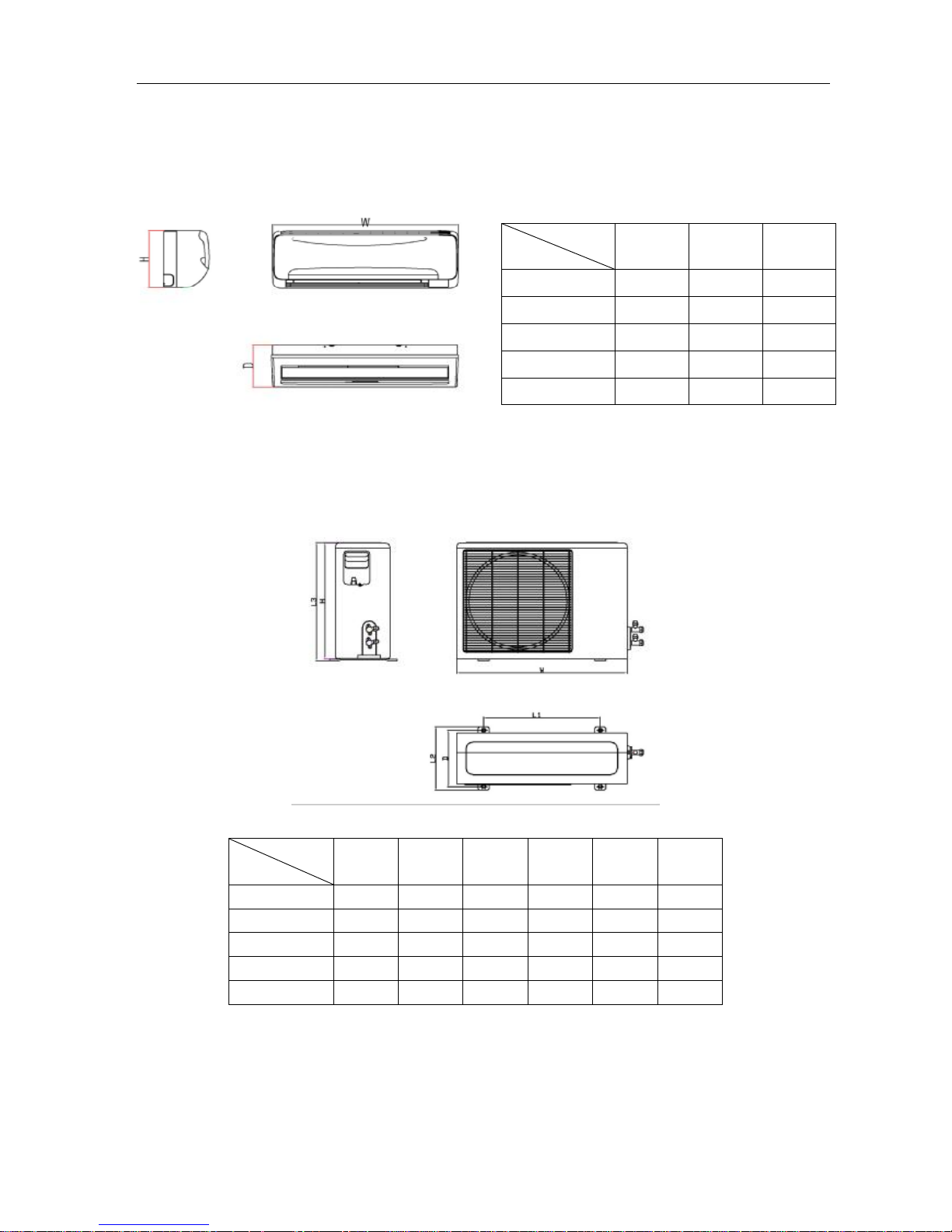
3. Dimension
3.1 Indoor unit
3.2 Outdoor unit
Dimension
Mode
W H D
7K 750 250 205
9K 750 250 205
12K 815 280 215
16K 920 293 224
18K 920 293 224
Dimension
Mode
W H D L1 L2 L3
7K 700 535 250 458 280 540
9K 700 535 250 458 280 540
12K 780 527 242 548 266 540
16K 780 527 242 548 266 540
18K 845 690 335 560 360 695
Page 7

Service manual
6
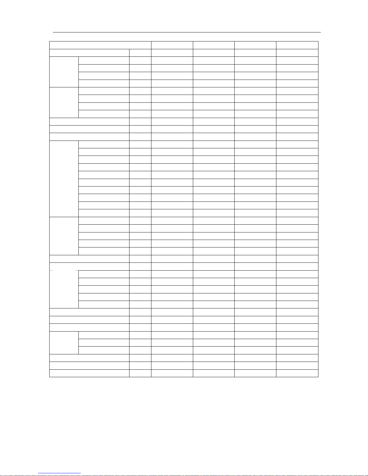
4. Specification
Model MSH-07CR MSH-07HR MSH-09CR MSH-09HR
Power supply Ph-V-Hz 1,220-240V, 50Hz 1,220-240V, 50Hz 1,220-240V, 50Hz 1,220-240V~, 50Hz
Capacity Btu/h 7000 7000 9000 9000
Input W 800 800 1000 1000
Rated current A 3.6 3.6 4.5 4.5
Cooling
EER Btu/w.h 8.8 8.8 9.0 9.0
Capacity Btu/h / 7600 / 10000
Input W / 760 / 980
Rated current A / 3.4 / 4.4
Heating
COP W/W / 2.9 / 3.0
Max. input consumption W 1050 1050 1300 1300
Max. current A 5 5 7 7
Starting current A 18 18 25 25
Model 2P14C235ANA 2P14C235ANA PH165X1CY-4DG2 2P18SS225ANK
Type Rotary Rotary Rotary Rotary
Brand GD Matsushita GD Matsushita GD Toshiba GD Matsushita
Capacity Btu/h 7500 7500 9380 9920
Input W 725 725 900 970
Rated current(RLA) A 3.4 3.4 4.1 4.5
Locked rotor Amp(LRA) A 15 15 24 24
Thermal protector MRA98854 MRA98854
UP3QE0591-T61
(internal)
MRA98745
(external)
Capacitor uF 25 25 25 30
Compressor
Refrigerant oil ml ATOMOS M60 270 ATOMOS M60 270 SUNISO 400 SUNISO 350
Model RPG13H RPG13H RPG13H RPG13H
Brand WEILING WEILING WEILING WEILING
Input W 36.5 36.5 36.5 36.5
Capacitor uF 1.2uf/450V 1.2uf/450V 1.2uf/450V 1.2uf/450V
Indoor
fan motor
Speed(hi/mi/lo) r/min 1020/920/900 1020/920/900 1100/1020/950 1100/1020/950
Indoor air flow (Hi/Mi/Lo) m3/h 380/350/320 380/350/320 450/420/390 450/420/390
Indoor noise level (Hi/Mi/Lo) dB(A) 35/33/31 35/33/31 37/35/32 37/35/32
Model YDK24-6T YDK24-6T YDK24-6F YDK24-6F
Brand WEILING WEILING WEILING WEILING
Input W 70 70 70 70
Capacitor uF 3 3 2.5 2.5
Outdoor
fan motor
Speed r/min 850 850 850 850
Outdoor air flow m3/h 1500 1400 1500 1500
Outdoor noise level dB(A) 52 52 53 53
Refrigerant type R22 g 580 620 580 700
Liquid side/ Gas side mm φ6.35/φ9.53 φ6.35/φ9.53 φ6.35/φ9.53 φ6.35/φ9.53
Max. pipe length m 10 10 10 10
Refrigerant
piping
Max. in level m 5 5 5 5
Operation temp ℃ 17-30 17-30 17-30 17-30
Ambient temp ℃ 17-45 -7-45 17-45 -7-45
Application area m2 10-14 10-14 14-21 14-21
Note:
The noise date is base on hemi-anechoic chamber, during actual operation; these values are normally somewhat
different as a result of ambient condition.
The above design and specifications are subject to change without prior notice for product improvement.
Page 8
Service manual
7
2Model MSH-12CR MSH-12HR MSH-16CR MSH-16HR
Power supply Ph-V-Hz 1, 220-240V, 50Hz 1, 220-240V, 50Hz 1,220-240V, 50Hz 1,220-240V, 50Hz
Capacity Btu/h 12000 12000 16000 16000
Input W 1280 1320 1760 1760
Rated current A 6 6.1 8.6 8.6
Cooling
EER Btu/w.h 9.4 9.1 9.09 9.09
Capacity Btu/h / 14000 / 18500
Input W / 1370 / 1850
Rated current A / 6.3 / 8.9
Heating
COP W/W / 3.0 / 2.93
Max. input consumption W 1850 1850 2400 2400
Max. current A 9.6 9.6 11 11
Starting current A 29 30 36 36
Model PH240X2C-4FT 2K25S225BUA PH290X2C-4FT1 PH290X2C-4FT1
Type Rotary Rotary Rotary Rotary
Brand GD Toshiba GD Matsushita GD Toshiba GD Toshiba
Capacity Btu/h 14000 14700 17435 17435
Input W 1355 1468 1670 1670
Rated current(RLA) A 6.3 6.8 8.0 8.0
Locked rotor Amp(LRA) A 29 30 41.2 41.2
Thermal protector Internal Internal Internal Internal
Capacitor uF 35 40 35 35
Compressor
Refrigerant oil ml 480 490 520 520
Model RPG20D RPG20D RPG28D RPG28D
Brand WEILING WEILING WEILING WEILING
Input W 49.2 49.2 55 55
Capacitor uF 1.5uf/450V 1.5uf/450V 1.5UF/450V 1.5UF/450V
Indoor fan
motor
Speed(hi/mi/lo) r/min 1220/1000/800 1220/1000/800 1180/1080/800 1180/1080/800
Indoor air flow (Hi/Mi/Lo) m3/h 560/520/480 560/520/480 850/700/600 850/700/600
Indoor noise level (Hi/Mi/Lo) dB(A) 38/32/28 38/32/28 44/41/38 44/41/38
Model YDK24-6 YDK25-6 YDK36-6 YDK36-6
Brand WEILING WEILING WEILING WEILING
Input W 72 96 96 96
Capacitor uF 2.5uf/450V 2.5uf/450V 2.5uf/450V 2.5uf/450V
Outdoor fan
motor
Speed r/min 850 900 900 900
Outdoor air flow m3/h 1900 1900 1800 1800
Outdoor noise level dB(A) 53 53 54 54
Refrigerant type R22 g 830 1080 1050 1400
Liquid side/ Gas side mm φ6.35/φ12.7 φ6.35/φ12.7 φ6.35/φ12.7 φ6.35/φ12.7
Max. pipe length m 10 10 10 10
Refrigerant
piping
Max. in level m 5 5 5 5
Operation temp ℃ 17-30 17-30 17-30 17-30
Ambient temp ℃ 17-45 -7-45 17-45 -7-45
Application area m2 18-26 18-26 28-40 28-40
Note:
The noise date is base on hemi-anechoic chamber, during actual operation; these values are normally somewhat
different as a result of ambient condition.
The above design and specifications are subject to change without prior notice for product improvement.
Page 9
Service manual
8
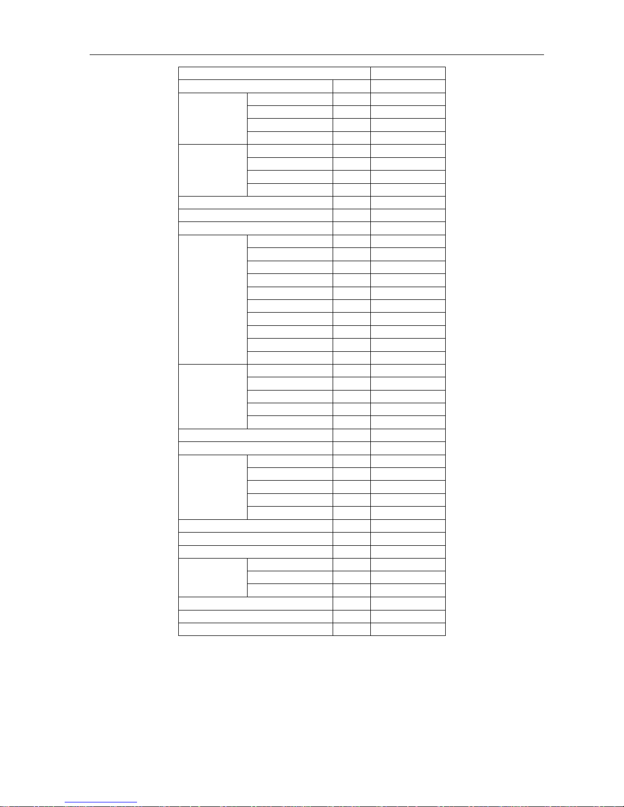
Model MSH-18CR
Power supply Ph-V-Hz 1, 220-240V~, 50Hz
Capacity Btu/h 18000
Input W 1980
Rated current A 9.0
Cooling
EER Btu/w.h 9.09
Capacity Btu/h /
Input W /
Rated current A /
Heating
COP W/W /
Max. input consumption W 2100
Max. current A 12.0
Starting current A 42
Model SHW33TC4-U
Type Rotary
Brand 上海日立
Capacity Btu/h 20438
Input W 1990
Rated current(RLA) A 9.3
Locked rotor Amp(LRA) A 41.2
Thermal protector Internal
Capacitor uF 50
Compressor
Refrigerant oil ml 600
Model RPG28D
Brand WEILING
Input W 55
Capacitor uF 1.5UF/450V
Indoor fan motor
Speed(hi/mi/lo) r/min 1180/1080/800
Indoor air flow (Hi/Mi/Lo) m3/h 850/700/600
Indoor noise level (Hi/Mi/Lo) dB(A) 44/41/38
Model YDK53-6
Brand WEILING
Input W 100
Capacitor uF 2.5uf
Outdoor fan motor
Speed r/min 640
Outdoor air flow m3/h 2200
Outdoor noise level dB(A) 54
Refrigerant type (R22) g 1220
Liquid side/ Gas side mm φ6.35/φ12.7
Max.pipe length m 15
Refrigerant piping
Max. in level m 8
Operation temp ℃ 17-30
Ambient temp ℃ 17-45
Application area m2 34-49
Note:
The noise date is base on hemi-anechoic chamber, during actual operation; these values are normally somewhat
different as a result of ambient condition.
The above design and specifications are subject to change without prior notice for product improvement.
Page 10

Service manual
9
5. Refrigerant cycle diagram
Ø Cooling only
Ø Heat pump mode
Page 11
Service manual
10
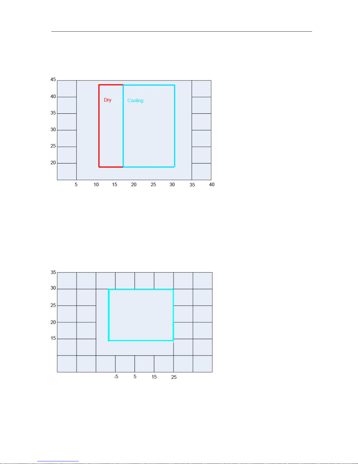
6. Operation limits
6.1 Cooling operation
Outdoor unit air temp.℃ DB
Indoor air temp. ℃ DB
Note: The chart is the result from the continuous operation under constant air temperature conditions.
However, excludes the initial pull-down stage.
6.2 Heating operation
Indoor air temp. ℃ DB
Outdoor unit air temp.℃ DB
Note: The chart is the result from the continuous operation under constant air temperature conditions.
However, excludes the initial pull-down stage.
Page 12
Service manual
12
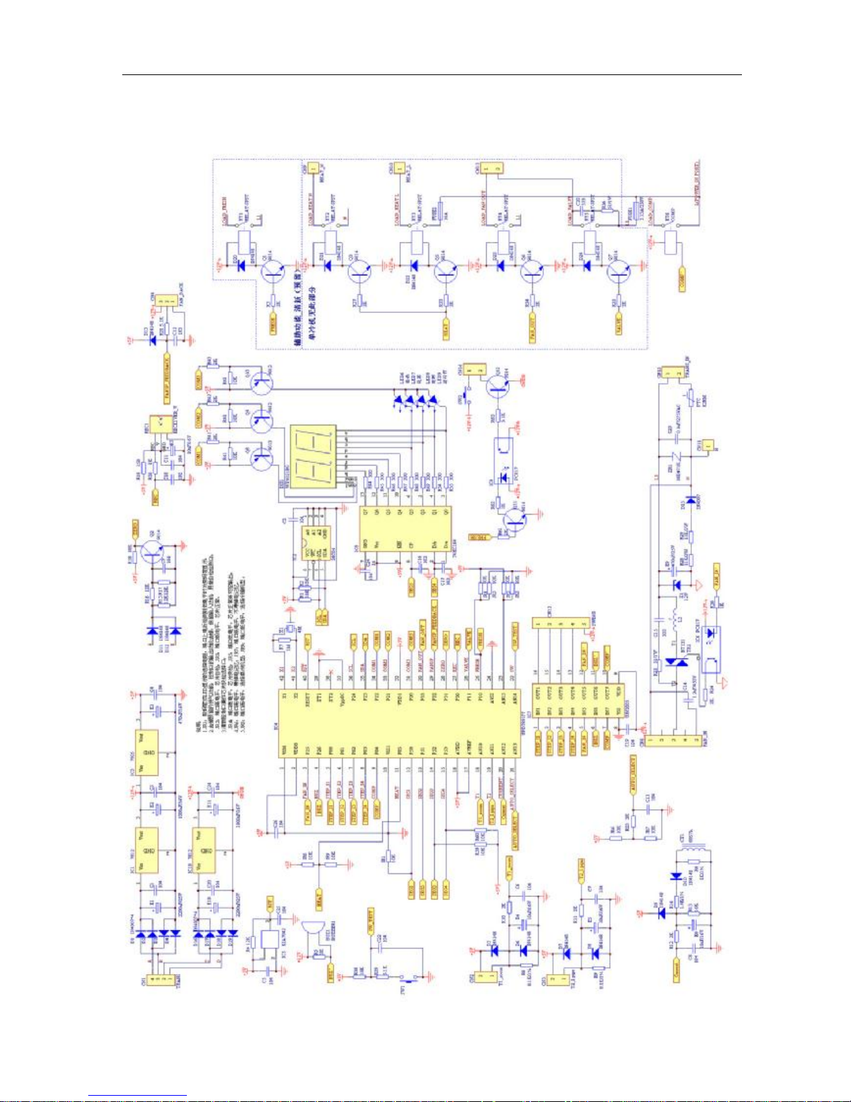
7. Schematic diagram and Wiring diagram
7.1. Schematic diagram
Page 13

Service manual
13
7.2. Wiring diagram
7.2.1 MSH-07CR, MSH-09CR,
Page 14

Service manual
14
Page 15

Service manual
15
7.2.2 MSH-12CR
Page 16

Service manual
16
7.2.3 MSH-16CR
Page 17

Service manual
17
7.2.4 MSH-18CR
Page 18

Service manual
18
7.2.4 MSH-07HR.MSH-09HR
Page 19

Service manual
19
7.2.5 MSH12HR
Page 20

Service manual
20
7.2.6 MSH-16HR
Page 21

Service manual
21
8. Installation details
8.1 Wrench torque sheet for installation
Outside diameter Torque
mm inch Kg.m
φ6.35
1/4 1.8
φ9.52
3/8 4.2
φ12.7
1/2 5.5
8.2 Connecting the cables
The power cord of connect should be selected according to the following specifications sheet.
Grade
Unit 7K 9K 12K 16K 18K
mm2 1.0 1.0 1.5 2.5 2.5
8.3 Pipe length and the elevation
Pipe size
Capacity
Btu/h
GAS LIQUID
Standard
length (m)
Max.
ElevationB
(m)
Max.
ElevationB
(m)
Additional
refrigerant
(g/m)
3/8’’ (φ
9.52)
1/4’’ (φ
6.35)
5 5 10 30
7k~12K
1/2’’ (φ
12.7)
1/4’’ (φ
6.35)
5 5 10 30
1/2’’ (φ
12.7)
1/4’’ (φ
6.35)
5 8 15 30
5/8’’ (φ
15.88)
1/4’’ (φ
6.35)
5 10 20 30
18K~28K
5/8’’ (φ
15.88)
3/8’’ (φ
9.52)
5 10 20 65
Page 22

Service manual
22
Caution:
Capacity is base on standard length and maximum allowance length is base of reliability.
Oil trap should be install per 5-7 meters.
In case that
more than 5m.
Page 23

Service manual
23
8.4 Air purging of the piping and indoor unit
Required tools:
Hexagonal wrench; adjustable wrench; torque wrenches, wrench to hold the joints and gas leak detector.
Note:
The air in the indoor unit and in the piping must be purged. If air remains in the refrigeration piping, it will
affect the compressor, reduce the cooling capacity, and could lead to a malfunction of unit.
Be sure, using a torque wrench to tighten the service port cap (after using the service port), so that it
prevents the gas leakage from the refrigeration cycle.
Procedure
1. Recheck the piping connections.
2. Open the valve stem of the 2-way valve
counterclockwise approximately 90’, wait
10 seconds, and then set it to closed
position.
§ Be sure to use a hexagonal wrench to operate
the valve stem
3. Check for gas leakage.
§ Check the flare connection for gas leakage
4. Purge the air from the system.
§ Set the 2-way valve to the open position and
remove the cap from the 3-way valve’s
service port.
§ Using the hexagonal wrench to press the
valve core pin, discharge for three seconds
and then wait for one minute.
5. Use torque wrench to tighten the service
port cap to a torque of 1.8 kg.m. (18n.m)
6. Set the 3-way valve to the opened
position.
7. Mounted the valve stem nuts to the 2-way
and 3-way valves.
8. Check for gas leakage.
§ At this time, especially check for gas leakage
from the 2-way and 3-way stem nuts, and
from the service port.
Caution:
If gas leakage is discovered in step (3) above,
take the following measures.
If the leaks stop when the piping connections are
tightened further, continue working from step (4).
If the gas leaks do not stop when the connections
are retightened, repair the location of the leak,
discharge all of the gas through the service port,
and then recharge with the specified amount of
gas from a gas cylinder.
Page 24

Service manual
24
8.5 Pumping down (Re-installation)
Procedure
1. Confirm that both the 2-way and 3-way valves are set to the opened position.
§ Remove the valve stem caps and confirm that the valve stems are in the opened position.
§ Be sure to use a hexagonal wrench to operate the valve stems.
2. Operate the unit for 10 to 15 minutes.
3. Stop operation and wait for 3 minutes, then connect the charge set to the service port of the
3-way valve.
§ Connect the charge hose with the push pin to the gas service port.
4. Air purging of the charge hose.
§ Open the low-pressure valve on the charge set slightly to purge air from the charge hose.
5. Set the 2-way valve to the close position.
6. Operate the air conditioner at the cooling cycle and stop it when the gauge indicates 0.1MPa.
7. Immediately set the 3-way valve to the closed position.
§ Do this quickly so that the gauge ends up indicating 0.3 to 0.5Mpa.
8. Disconnect the charge set, and amount the 2-way and 3-way valve’s stem nuts and service
port caps.
§ Use a torque wrench to tighten the service port cap to a torque of 1.8 kg.m.
§ Be sure to check for gas leakage.
Page 25

Service manual
25
8.6 Re-air purging (Re-installation)
Procedure:
1. Confirm that both the 2-way and 3-way valves are set to the closed position.
2. Connect the charge set and a charging cylinder to the service port of the 3-way valve.
§ Leave the valve on the charging cylinder closed.
3. Air purging.
§ Open the valves on the charging cylinder and the charge set. Purge the air by loosening the flare nut
on the 2-way valve approximately 45’ for 3 seconds then closing it for 1 minutes; repeat 3 times.
§ After purging the air, use a torque wrench to tighten the flare nut to on the 2-way valve.
4. Check the gas leakage.
§ Check the flare connections for gas leakage.
5. Discharge the refrigerant.
§ Close the valve on the charging cylinder and discharge the refrigerant until the gauge indicate 0.3 to
0.5 Mpa.
6. Disconnect the charge set and the charging cylinder, and set the 2-way and 3-way valves to
the open position.
§ Be sure to use a hexagonal wrench to operate the valve stems.
7. Mount the valve stems nuts and the service port cap.
§ Be sure to use a torque wrench to tighten the service port cap to a torque 18N.m.
§ Be sure to check the gas leakage.
Page 26

Service manual
26
8.7 Balance refrigerant of the 2-way, 3-way valves
Procedure:
1. Confirm that both the 2-way and 3-way valves are set to the open position.
2. Connect the charge set to the 3-way valve’s service port.
§ Leave the valve on the charge set closed.
§ Connect the charge hose with the push pin to the service port.
3. Open the valves (Low side) on the charge set and discharge the refrigerant until the gauge
indicates 0.05 to 0.1 Mpa.
§ If there is no air in the refrigeration cycle [the pressure when the air conditioner is not running is
higher than 0.1Mpa, discharge the refrigerant until the gauge indicates 0.05 to 0.1 Mpa. If this is the
case, it will not be necessary to apply a evacuation.
§ Discharge the refrigeration gradually; if it is discharged too suddenly, the refrigeration oil sill be
discharged.
Page 27

Service manual
27
8.8 Evacuation
Procedure:
1. Connect the vacuum pump to the charge set’s centre hose.
2. Evacuation for approximately one hour.
§ Confirm that the gauge needle has moved toward -0.1 Mpa (-76 cmHg) [vacuum of 4 mmHg or less].
3. Close the valve (Low side) on the charge set, turn off the vacuum pump, and confirm that the
gauge needle does not move (approximately 5 minutes after turning off the vacuum pump).
4. Disconnect the charge hose from the vacuum pump.
§ Vacuum pump oil, if the vacuum pump oil becomes dirty or depleted, replenish as needle.
Page 28

Service manual
28
8.9 Gas charging
Procedure:
1. Connect the charge hose to the charging cylinder.
§ Connect the charge hose which you disconnected from the vacuum pump to the valve at the bottom
of the cylinder.
2. Purge the air from the charge hose.
§ Open the valve at the bottom of the cylinder and press the check valve on the charge set to purge the
air (be careful of the liquid refrigerant).
3. Open the valves (Low side) on the charge set and charge the system with liquid refrigerant.
§ If the system cannot be charge with the specified amount of refrigerant, if can be charged with a little
at a time (approximately 150g each time0 while operating the air conditioner in the cooling cycle;
however, one time is not sufficient, wait approximately 1 minute and then repeat the
procedure.(pumping down-pin).
4. Immediately disconnect the charge hose from the 3-way valve’s service port.
§ Stopping partway will allow the refrigerant to be discharged.
§ If the system has been charged with liquid refrigerant while operating the air conditioner, turn off the
air conditioner before disconnecting the hose.
5. Mounted the valve stem caps and the service port
§ Use torque wrench to tighten the service port cap to a torque of 18N.m.
§ Be sure to check for gas leakage.
Page 29

Service manual
29
§
9. Pressure table
Note:
The pressure data is from 3 way valve, the pressure data are pressure above atmosphere.
D: Dry bulb temp.
W: Wet bulb temp.
9.1 MSH-07CR
Cooling mode
Outdoor temperature (Dry bulb temp)
Indoor Conditions Pressure 25ºC 30ºC 35ºC 40ºC 45ºC 50ºC
21ºC D15ºC W Pressure(kg/cm2 ) 4.1 4.2 4.3 4.4 4.5 4.6
24ºC D17ºC W Pressure(kg/cm2) 4.3 4.4 4.5 4.5 4.6 4.8
27ºC D19ºC W Pressure(kg/cm2) 4.4 4.5 4.7 4.9 5.1 5.2
32ºC D23ºC W Pressure(kg/cm2) 4.6 4.7 4.8 5.1 5.3 5.4
9.2 MSH-07HR
Cooling mode
Outdoor temperature (Dry bulb temp)
Indoor Conditions Pressure 25ºC 30ºC 35ºC 40ºC 45ºC 50ºC
21ºC D15ºC W Pressure(kg/cm2 ) 4.1 4.2 4.3 4.4 4.5 4.6
24ºC D17ºC W Pressure(kg/cm2) 4.3 4.4 4.5 4.5 4.6 4.8
27ºC D19ºC W Pressure(kg/cm2) 4.4 4.5 4.7 4.9 5.1 5.2
32ºC D23ºC W Pressure(kg/cm2) 4.6 4.7 4.8 5.1 5.3 5.4
Heating mode
OUTDOOR CONDITIONS
Indoor Conditions Pressure 12ºC D 7ºC D 0ºC D
-4ºC D -7ºC D -15ºC D
15ºC
Pressure( kg/cm
2
) 12.0 11.5 10.7 10.5 10.2 / 18ºC
Pressure( kg/cm
2
) 12.3 11.7 11.5 11.3 10.4 / 20ºC
Pressure( kg/cm
2
) 12.5 12.1 12.0 11.5 10.5 / 22ºC
Pressure( kg/cm
2
) 12.6 12.3 12.2 11.9 10.9 /
9.3 MSH-09CR
Cooling mode Outdoor temperature (Dry bulb temp)
21ºC D15ºC W Pressure( kg/cm2 ) 3.9 4.0 4.2 4.5 4.5 5.0
24ºC D17ºC W Pressure( kg/cm2 ) 4.0 4.1 4.3 4.5 4.7 5.1
27ºC D19ºC W Pressure( kg/cm2 ) 4.0 4.2 4.6 4.8 5.1 5.4
32ºC D23ºC W Pressure( kg/cm2 ) 4.4 4.1 4.6 5.0 5.2 5.6
9.4 MSH-09HR
Cooling mode Outdoor temperature (Dry bulb temp)
Indoor Conditions Pressure 25ºC 30ºC 35ºC 40ºC 45ºC 50ºC
21ºC D15ºC W Pressure( kg/cm2 ) 3.9 4.0 4.2 4.5 4.5 5.0
24ºC D17ºC W Pressure( kg/cm2 ) 4.0 4.1 4.3 4.5 4.7 5.1
27ºC D19ºC W Pressure( kg/cm2 ) 4.0 4.2 4.6 4.8 5.1 5.4
32ºC D23ºC W Pressure( kg/cm2 ) 4.4 4.1 4.6 5.0 5.2 5.6
Page 30

Service manual
30
Heating mode OUTDOOR CONDITIONS
Indoor Conditions Pressure
12ºC D
11ºC W
7ºC D
6ºC W
0ºC D
-1ºC W
-4ºC D
-6ºC W
-7ºC D
-9ºC W
-15ºC D
-xºC W
15ºC Pressure( kg/cm2 ) 13.2 12.5 11.0 10.7 10.2 /
18ºC Pressure( kg/cm2 ) 13.5 13.0 11.7 11.2 10.4 /
20ºC Pressure( kg/cm2 ) 13.7 13.2 12.5 11.5 10.5 /
22ºC Pressure( kg/cm2 ) 14.2 13.5 12.7 11.9 10.7 /
9.5 MSH-12CR
Cooling mode Outdoor temperature (Dry bulb temp)
Indoor Conditions Pressure 25ºC 30ºC 35ºC 40ºC 45ºC 50ºC
21ºC D15ºC W Pressure( kg/cm2 ) 4.1 4.2 4.4 4.4 4.7 4.9
24ºC D17ºC W Pressure( kg/cm2 ) 4.3 4.4 4.6 4.7 5.0 5.2
27ºC D19ºC W Pressure( kg/cm2 ) 4.4 4.6 4.7 4.9 5.1 5.4
32ºC D23ºC W Pressure( kg/cm2 ) 4.6 4.8 4.9 5.2 5.4 5.6
9.6 MSH-12HR
Cooling mode Outdoor temperature (Dry bulb temp)
Indoor Conditions Pressure 25ºC 30ºC 35ºC 40ºC 45ºC 50ºC
21ºC D15ºC W Pressure( kg/cm2 ) 4.1 4.2 4.4 4.4 4.7 4.9
24ºC D17ºC W Pressure( kg/cm2 ) 4.3 4.4 4.6 4.7 5.0 5.2
27ºC D19ºC W Pressure( kg/cm2 ) 4.4 4.6 4.7 4.9 5.1 5.4
32ºC D23ºC W Pressure( kg/cm2 ) 4.6 4.8 4.9 5.2 5.4 5.6
Heating mode OUTDOOR CONDITIONS
Indoor Conditions Pressure
12ºC D
11ºC W
7ºC D
6ºC W
0ºC D
-1ºC W
-4ºC D
-6ºC W
-7ºC D
-9ºC W
-15ºC D
-xºC W
15ºC Pressure( kg/cm2 ) 13.7 12.9 11.1 10.7 10.0 /
18ºC Pressure( kg/cm2 ) 14.9 13.6 11.9 11.0 10.5 /
20ºC Pressure( kg/cm2 ) 15.1 14.5 12.1 11.8 11.1 /
22ºC Pressure( kg/cm2 ) 16.2 15.0 12.7 12.0 11.3 /
9.7 MSH-16CR
Cooling mode Outdoor temperature (Dry bulb temp)
Indoor Conditions Pressure 25ºC 30ºC 35ºC 40ºC 45ºC 50ºC
21ºC D15ºC W Pressure( kg/cm2 ) 4.2 4.3 4.4 4.5 4.7 4.9
24ºC D17ºC W Pressure( kg/cm2 ) 4.3 4.5 4.6 4.7 5.0 5.2
27ºC D19ºC W Pressure( kg/cm2 ) 4.4 4.6 4.7 4.9 5.2 5.4
32ºC D23ºC W Pressure( kg/cm2 ) 4.6 4.8 4.9 5.2 5.4 5.7
Page 31

Service manual
31
9.8 MSH-16HR
Cooling mode Outdoor temperature (Dry bulb temp)
Indoor Conditions Pressure 25ºC 30ºC 35ºC 40ºC 45ºC 50ºC
21ºC D15ºC W Pressure( kg/cm2 ) 4.2 4.3 4.4 4.5 4.7 4.9
24ºC D17ºC W Pressure( kg/cm2 ) 4.3 4.5 4.6 4.7 5.0 5.2
27ºC D19ºC W Pressure( kg/cm2 ) 4.4 4.6 4.7 4.9 5.2 5.4
32ºC D23ºC W Pressure( kg/cm2 ) 4.6 4.8 4.9 5.2 5.4 5.7
Heating mode OUTDOOR CONDITIONS
Indoor Conditions Pressure
12ºC D
11ºC W
7ºC
D
6ºC W
0ºC D
-1ºC W
-4ºC D
-6ºC W
-7ºC D
-9ºC W
-15ºC D
-xºC W
15ºC Pressure( kg/cm2 ) 14.1 13.0 10.7 10.3 10.1 /
18ºC Pressure( kg/cm2 ) 15.3 14.1 12.3 11.4 11.1 /
20ºC Pressure( kg/cm2 ) 15.6 14.9 12.6 12.3 11.6 /
22ºC Pressure( kg/cm2 ) 16.6 15.6 13.1 12.6 11.9 /
9.9 MSH-18CR
Cooling mode Outdoor temperature (Dry bulb temp)
Indoor Conditions Pressure 25ºC 30ºC 35ºC 40ºC 45ºC 50ºC
21ºC D15ºC W Pressure( kg/cm2 ) 4.3 4.3 4.4 4.5 4.7 4.9
24ºC D17ºC W Pressure( kg/cm2 ) 4.4 4.5 4.6 4.7 5.0 5.2
27ºC D19ºC W Pressure( kg/cm2 ) 4.5 4.6 4.7 4.9 5.2 5.5
32ºC D23ºC W Pressure( kg/cm2 ) 4.6 4.6 4.9 5.2 5.4 5.7
Page 32

Service manual
32
10. Capacity table
10.1 MSH-07CR
SUMMER OUTDOOR TEMPERATURE DRY
Indoor Conditions 25ºC 30ºC 35ºC 40ºC 45ºC 50ºC
Total capacity kW 2.02 1.92 1.79 1.64 1.51 1.41
Sensitive capacity kW 1.44 1.39 1.34 1.27 1.20 1.15
21ºC D
15ºC W
Input kW. 0.70 0.76 0.82 0.88 0.95 1.00
Total capacity kW 2.16 2.07 1.95 1.83 1.71 1.60
Sensitive capacity kW 1.53 1.48 1.43 1.38 1.34 1.32
24ºC D
17ºC W
Input kW. 0.70 0.77 0.84 0.90 0.97 1.03
Total capacity kW 2.32 2.27 2.15 1.98 1.81 1.65
Sensitive capacity kW 1.65 1.62 1.56 1.48 1.41 1.34
27ºC D
19ºC W
Input kW. 0.72 0.79 0.85 0.92 0.99 1.05
Total capacity kW 2.36 2.39 2.36 2.28 2.18 2.07
Sensitive capacity kW 1.57 1.59 1.57 1.55 1.53 1.54
32ºC D
23ºC W
Input kW. 0.71 0.19 0.87 0.95 1.03 1.10
10.2 MSH-07HR
SUMMER OUTDOOR TEMPERATURE DRY
Indoor Conditions 25ºC 30ºC 35ºC 40ºC 45ºC 50ºC
Total capacity kW 2.02 1.92 1.79 1.64 1.51 1.41
Sensitive capacity kW 1.44 1.39 1.34 1.27 1.20 1.15
21ºC D
15ºC W
Input kW. 0.70 0.76 0.82 0.88 0.95 1.00
Total capacity kW 2.16 2.07 1.95 1.83 1.71 1.60
Sensitive capacity kW 1.53 1.48 1.43 1.38 1.34 1.32
24ºC D
17ºC W
Input kW. 0.70 0.77 0.84 0.90 0.97 1.03
Total capacity kW 2.32 2.27 2.15 1.98 1.81 1.65
Sensitive capacity kW 1.65 1.62 1.56 1.48 1.41 1.34
27ºC D
19ºC W
Input kW. 0.72 0.79 0.85 0.92 0.99 1.05
Total capacity kW 2.36 2.39 2.36 2.28 2.18 2.07
Sensitive capacity kW 1.57 1.59 1.57 1.55 1.53 1.54
32ºC D
23ºC W
Input kW. 0.71 0.19 0.87 0.95 1.03 1.10
WINTER OUTDOOR CONDITIONS
Indoor Conditions
12ºC D
11ºC W
7ºC D
6ºC W
4ºC D
3ºC W
0ºC D
-1ºC W
-4ºC D
-6ºC W
-7ºC D
-8ºC W
Capacity kW 2.75 2.45 2.17 1.40 1.17 1.13
15ºC
Input kW. 0.97 0.86 0.77 0.67 0.62 0.65
Capacity kW 2.60 2.33 2.10 1.33 1.23 1.09
18ºC
Input kW. 0.99 0.86 0.78 0.71 0.68 0.68
Capacity kW 2.58 2.35 2.08 1.27 1.14 1.11
20ºC
Input kW. 1.02 0.90 0.81 0.71 0.67 0.64
Capacity kW 2.40 2.29 1.99 1.07 1.15 1.07
22ºC
Input kW. 0.94 0.89 0.81 0.70 0.68 0.63
Page 33

Service manual
33
10.3 MSH-09CR
SUMMER OUTDOOR TEMPERATURE DRY
Indoor Conditions 25ºC 30ºC 35ºC 40ºC 45ºC 50ºC
Total capacity kW 2.44 2.32 2.16 1.98 1.82 1.70
Sensitive capacity kW 1.68 1.63 1.56 1.48 1.40 1.34
21ºC D
15ºC W
Input kW. 0.87 0.95 1.02 1.09 1.17 1.24
Total capacity kW 2.62 2.50 2.36 2.20 2.07 1.94
Sensitive capacity kW 1.78 1.73 1.67 1.61 1.56 1.54
24ºC D
17ºC W
Input kW. 0.87 0.95 1.03 1.11 1.20 1.28
Total capacity kW 2.80 2.75 2.60 2.40 2.18 1.99
Sensitive capacity kW 1.93 1.89 1.82 1.73 1.64 1.57
27ºC D
19ºC W
Input kW. 0.89 0.97 1.05 1.14 1.22 1.30
Total capacity kW 2.85 2.90 2.86 2.76 2.63 2.50
Sensitive capacity kW 1.83 1.85 1.84 1.81 1.78 1.79
32ºC D
23ºC W
Input kW. 0.88 0.98 1.07 1.17 1.27 1.37
10.4 MSH-09HR
SUMMER OUTDOOR TEMPERATURE DRY
Indoor Conditions 25ºC 30ºC 35ºC 40ºC 45ºC 50ºC
Total capacity kW 2.44 2.32 2.16 1.98 1.82 1.70
Sensitive capacity kW 1.68 1.63 1.56 1.48 1.40 1.34
21ºC D
15ºC W
Input kW. 0.87 0.95 1.02 1.09 1.17 1.24
Total capacity kW 2.62 2.50 2.36 2.20 2.07 1.94
Sensitive capacity kW 1.78 1.73 1.67 1.61 1.56 1.54
24ºC D
17ºC W
Input kW. 0.87 0.95 1.03 1.11 1.20 1.28
Total capacity kW 2.80 2.75 2.60 2.40 2.18 1.99
Sensitive capacity kW 1.93 1.89 1.82 1.73 1.64 1.57
27ºC D
19ºC W
Input kW. 0.89 0.97 1.05 1.14 1.22 1.30
Total capacity kW 2.85 2.90 2.86 2.76 2.63 2.50
Sensitive capacity kW 1.83 1.85 1.84 1.81 1.78 1.79
32ºC D
23ºC W
Input kW. 0.88 0.98 1.07 1.17 1.27 1.37
WINTER OUTDOOR CONDITIONS
Indoor Conditions
12ºC D
11ºC W
7ºC D
6ºC W
4ºC D
3ºC W
0ºC D
-1ºC W
-4ºC D
-6ºC W
-7ºC D
-8ºC W
Capacity kW 3.58 3.18 2.80 1.82 1.52 1.47
15ºC
Input kW. 1.18 1.05 0.94 0.81 0.75 0.80
Capacity kW 3.37 3.02 2.72 1.73 1.60 1.41
18ºC
Input kW. 1.20 1.05 0.96 0.86 0.83 0.84
Capacity kW 3.35 3.05 2.70 1.64 1.48 1.44
20ºC
Input kW. 1.24 1.08 0.98 0.86 0.82 0.82
Capacity kW 3.11 2.97 2.57 1.40 1.50 1.39
22ºC
Input kW. 1.14 1.07 0.98 0.86 0.82 0.79
Page 34

Service manual
34
10.5 MSH-12CR
SUMMER OUTDOOR TEMPERATURE DRY
Indoor Conditions 25ºC 30ºC 35ºC 40ºC 45ºC 50ºC
Total capacity kW 3.38 3.21 2.99 2.75 2.52 2.35
Sensitive capacity kW 2.53 2.28 2.18 2.07 1.96 1.88
21ºC D
15ºC W
Input kW. 1.20 1.30 1.41 1.51 1.61 1.72
Total capacity kW 3.62 3.46 3.26 3.06 2.86 2.68
Sensitive capacity kW 2.50 2.42 2.34 2.25 2.19 2.16
24ºC D
17ºC W
Input kW. 1.20 1.31 1.43 1.54 1.65 1.76
Total capacity kW 3.88 3.80 3.60 3.32 3.02 2.76
Sensitive capacity kW 2.71 2.65 2.55 2.42 2.30 2.19
27ºC D
19ºC W
Input kW. 1.23 1.34 1.45 1.57 1.68 1.80
Total capacity kW 3.95 4.01 3.95 3.82 3.64 3.46
Sensitive capacity kW 2.56 2.59 2.57 2.53 2.50 2.51
32ºC D
23ºC W
Input kW. 1.22 1.35 1.48 1.62 1.75 1.89
10.6 MSH-12HR
SUMMER OUTDOOR TEMPERATURE DRY
Indoor Conditions 25ºC 30ºC 35ºC 40ºC 45ºC 50ºC
Total capacity kW 3.38 3.21 2.99 2.75 2.52 2.35
Sensitive capacity kW 2.53 2.28 2.18 2.07 1.96 1.88
21ºC D
15ºC W
Input kW. 1.20 1.30 1.41 1.51 1.61 1.72
Total capacity kW 3.62 3.46 3.26 3.06 2.86 2.68
Sensitive capacity kW 2.50 2.42 2.34 2.25 2.19 2.16
24ºC D
17ºC W
Input kW. 1.20 1.31 1.43 1.54 1.65 1.76
Total capacity kW 3.88 3.80 3.60 3.32 3.02 2.76
Sensitive capacity kW 2.71 2.65 2.55 2.42 2.30 2.19
27ºC D
19ºC W
Input kW. 1.23 1.34 1.45 1.57 1.68 1.80
Total capacity kW 3.95 4.01 3.95 3.82 3.64 3.46
Sensitive capacity kW 2.56 2.59 2.57 2.53 2.50 2.51
32ºC D
23ºC W
Input kW. 1.22 1.35 1.48 1.62 1.75 1.89
WINTER OUTDOOR CONDITIONS
Indoor Conditions
12ºC D
11ºC W
7ºC D
6ºC W
4ºC
3ºC W
0ºC D
-1ºC W
-4ºC D
-6ºC W
-7ºC D
-8ºC W
Capacity kW 4.81 4.28 3.78 2.45 2.04 1.97
15ºC
Input kW. 1.61 1.44 1.29 1.11 1.03 0.99
Capacity kW 4.53 4.06 3.66 2.32 2.14 1.98
18ºC
Input kW. 1.65 1.44 1.31 1.18 1.14 1.02
Capacity kW 4.50 5.42 3.63 2.21 1.98 1.94
20ºC
Input kW. 1.69 1.48 1.34 1.18 1.12 1.03
Capacity kW 4.20 3.99 3.46 1.87 2.00 1.87
22ºC
Input kW. 1.78 1.48 1.35 1.12 1.13 1.07
Page 35

Service manual
35
10.7 MSH-16CR
SUMMER OUTDOOR TEMPERATURE DRY
Indoor Conditions 25ºC 30ºC 35ºC 40ºC 45ºC 50ºC
Total capacity kW 4.51 4.28 3.99 3.67 3.36 3.14
Sensitive capacity kW 3.43 3.25 3.00 2.78 2.56 2.40
21ºC D
15ºC W
Input kW. 1.44 1.56 1.69 1.81 1.94 2.06
Total capacity kW 4.83 4.62 4.35 4.08 3.82 3.58
Sensitive capacity kW 3.67 3.52 3.32 3.10 2.91 2.73
24ºC D
17ºC W
Input kW. 1.42 1.59 1.72 1.84 1.98 2.11
Total capacity kW 5.17 5.06 4.80 4.42 4.03 3.68
Sensitive capacity kW 3.87 3.85 3.74 3.32 3.06 2.76
27ºC D
19ºC W
Input kW. 1.48 1.61 1.74 1.88 2.02 2.16
Total capacity kW 5.41 5.36 5.28 5.11 4.87 4.63
Sensitive capacity kW 4.15 4.13 4.07 3.94 3.75 3.57
32ºC D
23ºC W
Input kW. 1.52 1.63 1.78 1.92 2.05 2.19
10.8 MSH-16HR
SUMMER OUTDOOR TEMPERATURE DRY
Indoor Conditions 25ºC 30ºC 35ºC 40ºC 45ºC 50ºC
Total capacity kW 4.51 4.28 3.99 3.67 3.36 3.14
Sensitive capacity kW 3.43 3.25 3.00 2.78 2.56 2.40
21ºC D
15ºC W
Input kW. 1.44 1.56 1.69 1.81 1.94 2.06
Total capacity kW 4.83 4.62 4.35 4.08 3.82 3.58
Sensitive capacity kW 3.67 3.52 3.32 3.10 2.91 2.73
24ºC D
17ºC W
Input kW. 1.42 1.59 1.72 1.84 1.98 2.11
Total capacity kW 5.17 5.06 4.80 4.42 4.03 3.68
Sensitive capacity kW 3.87 3.85 3.74 3.32 3.06 2.76
27ºC D
19ºC W
Input kW. 1.48 1.61 1.74 1.88 2.02 2.16
Total capacity kW 5.41 5.36 5.28 5.11 4.87 4.63
Sensitive capacity kW 4.15 4.13 4.07 3.94 3.75 3.57
32ºC D
23ºC W
Input kW. 1.52 1.63 1.78 1.92 2.05 2.19
WINTER OUTDOOR CONDITIONS
Indoor Conditions
12ºC D
11ºC W
7ºC D
6ºC W
4ºC D
3ºC W
0ºC D
-1ºC W
-4ºC D
-6ºC W
-7ºC D
-8ºC W
Capacity kW 6.36 5.65 5.00 3.23 2.70 2.60
15ºC
Input kW. 2.01 1.80 1.61 1.39 1.29 1.19
Capacity kW 5.99 5.36 5.27 3.35 3.09 2.78
18ºC
Input kW. 2.06 1.80 1.99 1.80 1.73 1.48
Capacity kW 5.46 5.42 4.80 2.92 2.63 2.56
20ºC
Input kW. 2.11 1.85 1.68 1.47 1.40 1.24
Capacity kW 5.53 5.27 4.57 2.48 2.64 2.52
22ºC
Input kW. 1.96 1.85 1.69 1.47 1.41 1.26
Page 36

Service manual
36
10.9 MSH-18CR
SUMMER OUTDOOR TEMPERATURE DRY
Indoor Conditions 25ºC 30ºC 35ºC 40ºC 45ºC 50ºC
Total capacity kW 4.69 4.45 4.15 3.81 3.50 3.27
Sensitive capacity kW 3.28 3.18 3.04 2.88 2.74 2.62
21ºC D
15ºC W
Input kW. 1.70 1.84 1.99 2.14 2.28 2.43
Total capacity kW 5.03 4.81 4.53 4.25 3.97 3.73
Sensitive capacity kW 3.47 3.37 3.25 3.13 3.04 3.00
24ºC D
17ºC W
Input kW. 1.70 1.86 2.02 2.17 2.33 2.50
Total capacity kW 5.38 5.28 5.00 4.61 4.20 3.83
Sensitive capacity kW 3.77 3.69 3.55 3.38 3.20 3.06
27ºC D
19ºC W
Input kW. 1.73 1.90 2.05 2.22 2.38 2.54
Total capacity kW 5.68 5.57 5.49 5.30 5.06 4.81
Sensitive capacity kW 3.57 3.61 3.58 3.52 3.48 3.50
32ºC D
23ºC W
Input kW. 1.72 1.91 2.10 2.29 2.48 2.67
Page 37

Service manual
44
12. Model and Parameters
Model
MSH-
07
CR
MSH-07
HR
MSH-09
CR
MSH-
09
HR
MSH-12
CR
MSH-12
HR
MSH-16
CR
MSH-16
HR
MSH-18
CR
I3SEC
8.5A
8.5A
10.0A
10.0A
14.5A
14.5A
16.0A
16.0A
17.0A
I5MIN
6.2A
6.2A
7.5A
7.5A
13.5A
13.5A
13.0A
13.0A
16.0A
IFAN
5.2A
5.2A
5.5A
5.5A
9.5A
9.5A
11.0A
11.0A
14.0A
IRESTORE
4.2A 4.2A
4.5A
4.5A
8.5A
8.5A
9.5A
9.5A
12A IDEFROST
3.5A
3.5A
6.5A
7.5A
TE1 34 34
TE2 37 36
TE3 33 30
TE4 22 20
TE5 4℃ 2 2 3 3 3
TE6 10℃ 7 7 14 14 14
TE7 62 60 TE8 56 52
TE9 50 50
ANGLCOOL
200 200 200 200 170 170 185 185 50 ANGLHEAT
0 0 10 20 ANGLOFF
124 124 124 124 124 124 120 120 0 THDEFROST
14 14 19 17 TMDEFROST
15 15 20 18 TLDEFROST
16 16 21 19
Page 38

Service manual
45
13. Troubleshooting
13.1 Display board
1
2
3
4
5
6
Infrared Signal
Receiver
§ Operation
The indicator flashes once every second after power is on and illuminates when the air conditioner is in
operation.
§ Timer indicator:
The indicator illuminates then TIMER is set ON.
§ PRE-DEF. indicator (For cooling & heating mode only)
The air conditioner starts defrosting automatically if outdoor unit frosts in heating operating.
At this time, PRE-DEF. indicator illuminates.
§ Auto indicator:
This indicator flashes when the air conditioner is in AUTO operation.
§ ECON indicator
This indicator illuminates while the air conditioner is in economic operation.
13.2 Troubleshooting
For cooling mode:
Failure phenomenon
Operation
lamp
Timer
lamp
Indoor fan speed has been out of control for over 1 minute
X
Indoor room temp. or evaporator sensor is open circuit or short circuit
On
Over current protection of the compressor occurs 4 times
X
EEROM error
On
No over-zero signal
r
Extinguish
Flash at 5Hz
For heat pump mode:
Failure phenomenon
Operation
lamp
Timer
lamp
Defrosting
lamp
Over current protection of the compressor occurs 4 times
X
Indoor fan speed has been out of control for over 1 minute
X
No over-zero signal
Temp. sensor on indoor evaporator is open circuit or short circuit
X
X
Indoor room temp. sensor is open circuit or short circuit
X
X
EEROM error
On
Xr Extinguish
Flash at 5Hz
Page 39

Service manual
46
13.3 Diagnostic chart
After energizing, no indicator is lighted and the air conditioner can’t be operated.
Page 40

Service manual
47
13.4 Resetting phenomenon often occurs during operation
(That is automatically entering to the status when power is on.)
The reason is that the instantaneous voltage of main chip is less than 4.5V. Check according to the
following procedure:
Resetting phenomenon often occurs during operation.
After changing indoor PCB, check if the failure realease.
Yes
After changing indoor fan motor, check if the failure realease.
Yes
YES
Yes
Power supply circuit has problems.
Indoor PCB is defective.
13.5 Operation lamp flashes and Timer lamp off
13.6 Operation lamp flashes and Timer lamp on
Page 41

Service manual
48
13.7 Operation lamp off and Timer lamp flashes
13.8 Operation lamp on and Timer lamp flashes
EEROM error, indoor PCB is defective.
13.9 Operation lamp flashes, Timer lamp flashes
This is alarm signal when the main chip can’t detect over-zero signal. When such failure occurs, the
main control board must have fault.
Page 42

Service manual
49
14. Characteristic of temperature sensor
Temp.℃ Resistance KΩ Temp.℃ Resistance KΩ Temp.℃ Resistance KΩ
-10 62.2756 17 14.6181 44 4.3874
-9 58.7079 18 13.918 45 4.2126
-8 56.3694 19 13.2631 46 4.0459
-7 52.2438 20 12.6431 47 3.8867
-6 49.3161 21 12.0561 48 3.7348
-5 46.5725 22 11.5 49 3.5896
-4 44 23 10.9731 50 3.451
-3 41.5878 24 10.4736 51 3.3185
-2 39.8239 25 10 52 3.1918
-1 37.1988 26 9.5507 53 3.0707
0 35.2024 27 9.1245 54 2.959
1 33.3269 28 8.7198 55 2.8442
2 31.5635 29 8.3357 56 2.7382
3 29.9058 30 7.9708 57 2.6368
4 28.3459 31 7.6241 58 2.5397
5 26.8778 32 7.2946 59 2.4468
6 25.4954 33 6.9814 60 2.3577
7 24.1932 34 6.6835 61 2.2725
8 22.5662 35 6.4002 62 2.1907
9 21.8094 36 6.1306 63 2.1124
10 20.7184 37 5.8736 64 2.0373
11 19.6891 38 5.6296 65 1.9653
12 18.7177 39 5.3969 66 1.8963
13 17.8005 40 5.1752 67 1.830
14 16.9341 41 4.9639 68 1.7665
15 16.1156 42 4.7625 69 1.7055
16 15.3418 43 4.5705 70 1.6469
 Loading...