

Page 1

CONTENTS
1. DIAGNOSTIC CHART 1
2. The service rules of the R407C(R410a) product 5
3. BRIGHT STAR SERIES 8
4. BRIGHT ECO SERIES 45
5. GLORY (ECO)STAR SERIES 65
6. GLORY GIANT 1 97
7. GLORY GIANT 2 115
8. LIGHT STAR SERIES 127
9. CUTE STAR SERIES 139
10. Beta GLORY R407 157
11. AC INVERT SERIES 178
MULTI INVERTER ECO 197
12.
13. Multi-system 1 to 2 214
14. Multi-system 1 to 3 228
15. Alfa Glory H series
(R410A) 244
16. DC inverter(R410A) 276
17. F1 STAR SERIES 305
18. Alfa Glory H series 330
Page 2

AFLA GLORY SERIES (R410A)
Contents
1. Features………………………………………………………………… 245
2. Specification………………………………………………………..……246
3. Dimensions…………………………………………………………..… 249
4. Refrigeration cycle diagram……………………………………………252
5. Pressure table…………….……………………………………….……253
6. Capacity table…………………………………………………………...256
7. Wiring diagram…………………………………………………..………261
8. Electronic function………………………………………….…………...265
9. Troubleshooting……………………………………………………….…273
10. Characteristic of temp. sensor…………………………………………278
Page 3

1.Features
1.1 Compact design
1.2 High efficiency and quiet operation
1.3 A class energy level
245
Page 4
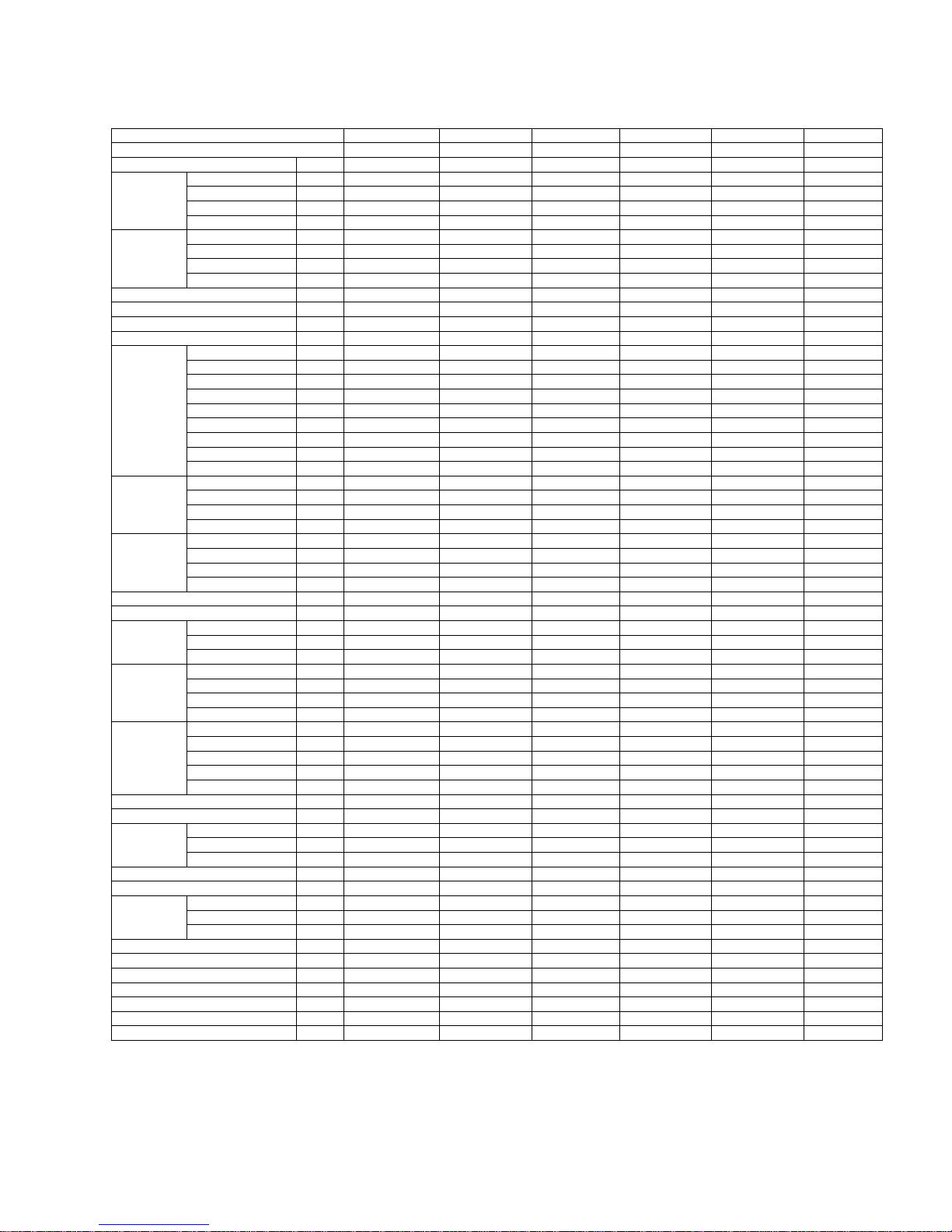
2.Specification
-
-
-
-
-
-
-
-
-
-
-
-
-
-
-
-
-
-
-
-
~
-
~
-
~
-
~
-
~
-
~
Cooling
——
——
——
Heating
——
-
-
-
-
-
-
-
-
-
-
-
-
Compressor
Indoor fan motor
Indoor coil
*
*
*
*
*
*
*
*
*
*
*
*
*
*
*
*
Indoor unit
-
-
-
-
-
-
Outdoor fan motor
Outdoor coil
*
*
*
*
Outdoor unit
Refrigerant piping
-
-
-
-
-
-
~-
-
-~
~-
-
-~
~-
-
-~
-
-
-
-
-
-
’
’’'
★1 The noise date is base on hemi-anechoic chamber, during actual operation, these values are normally somewhat different as a result of ambient
condition.
246
Page 5
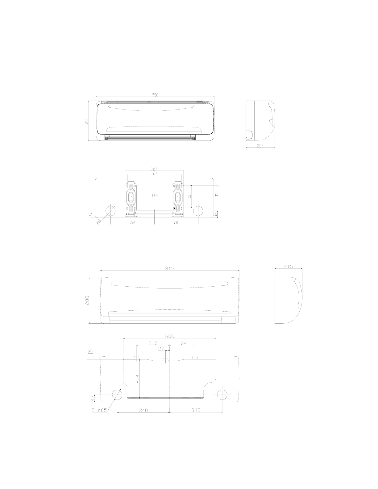
3.Dimensions
3.1 Indoor unit
MSH-07CRN1, MSH-07HRN1, MSH-09CRN1, MSH-09HRN1
3.2 Indoor unit
MSH-12CRN1, MSH-12HRN1
247
Page 6
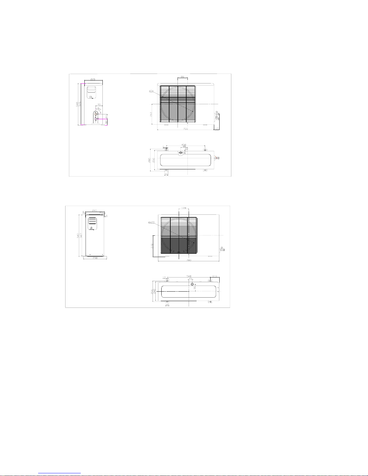
3.4 Outdoor unit
MSH-07CRN1, MSH-07HRN1
3.5 Outdoor unit
MSH-09CRN1, MSH-09HRN1
248
Page 7
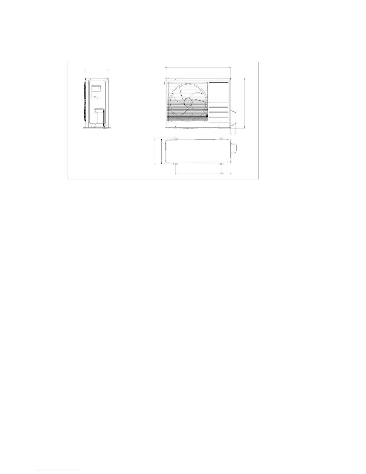
3.6 Outdoor unit
MSH-12CRN1, MSH-12HRN1
530
315
290
750
110
62
590
285
249
Page 8
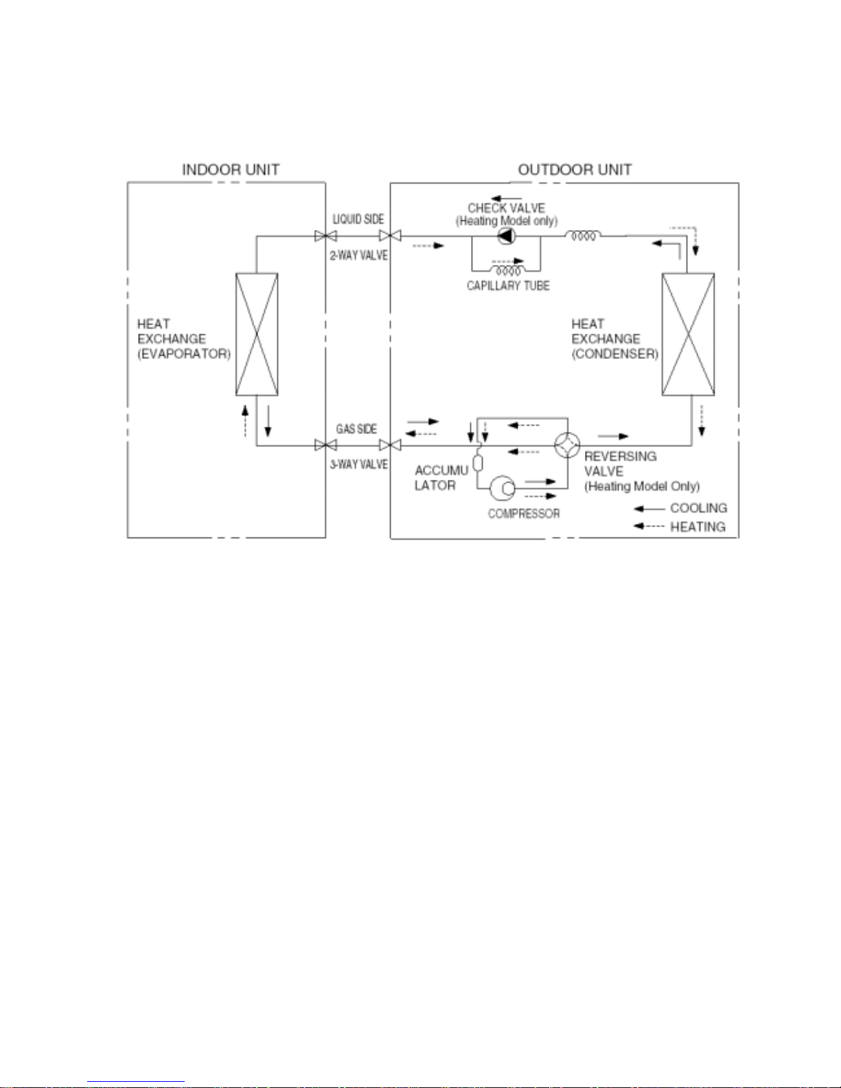
4.Refrigeration cycle diagram
250
Page 9
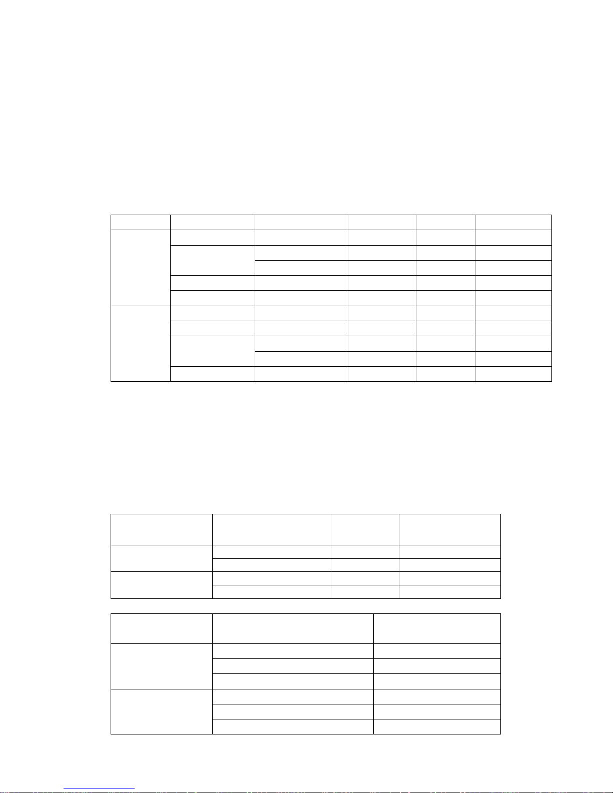
5. Pressure table
Note:
*The pressure data is from 3 way valve, the pressure data are pressure above atmosphere.
*D: Dry bulb temp.
*W: Wet bulb temp.
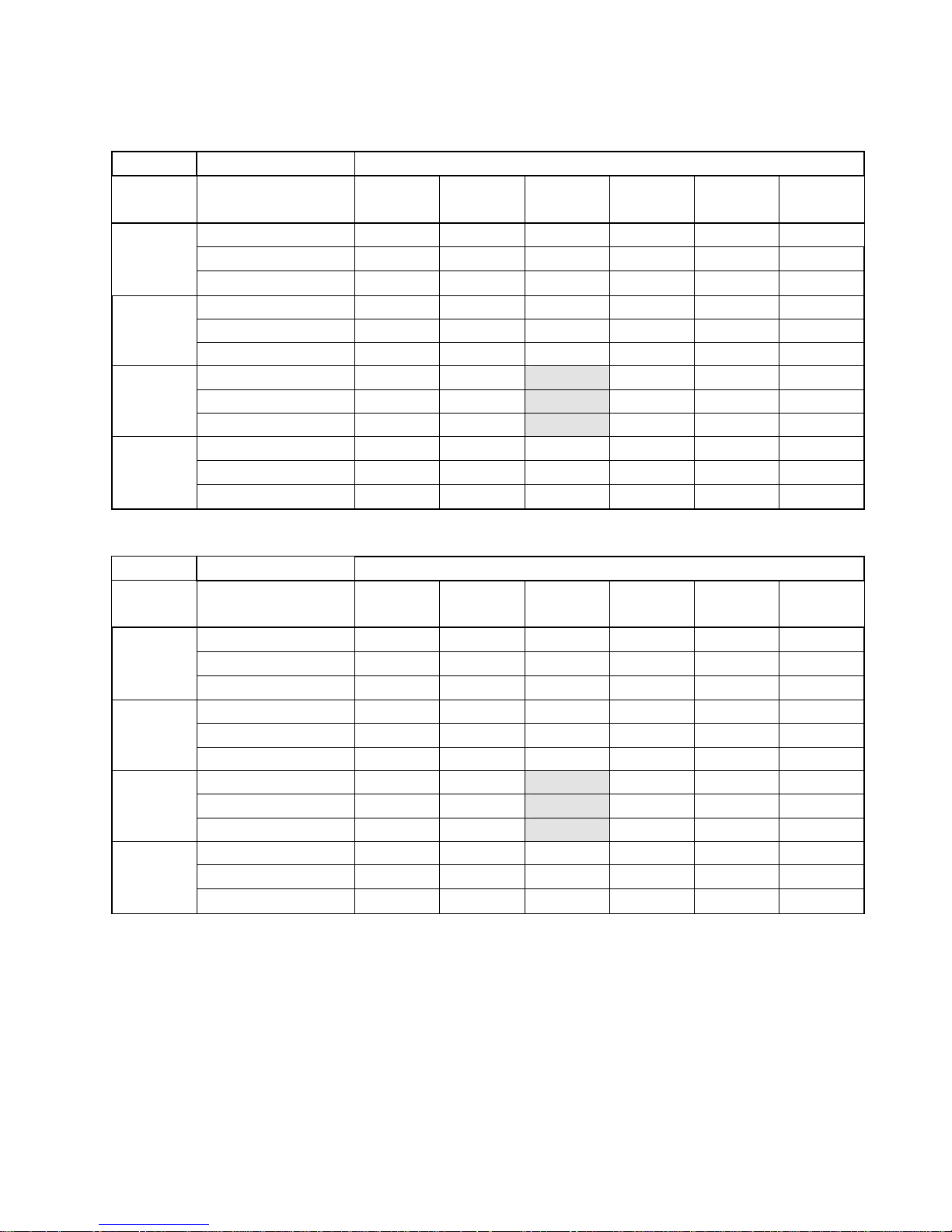
5.1 MSH-07CRN1
Cooling mode Outdoor temperature (Dry bulb temp)
Indoor Conditions
Pressure 25ºC 30ºC 35ºC 40ºC 45ºC 50ºC
21ºC D
15ºC W
Pressure
( kg/cm2 )
6.2 6.8 7.2 8.0 8.5 9.5
24ºC D
17ºC W
Pressure
( kg/cm2 )
6.3 6.5 7.5 8.0 8.7 9.5
27ºC D
19ºC W
Pressure
( kg/cm2 )
6.1 6.9 7.7 8.2 9.1 10.0
32ºC D
23ºC W
Pressure
( kg/cm2 )
7.0 7.3 7.8 8.3 9.2 10.1
5.2 MSH-07HRN1
Cooling mode Outdoor temperature (Dry bulb temp)
Indoor
Conditions
Pressure 25ºC 30ºC 35ºC 40ºC 45ºC 50ºC
21ºC D
15ºC W
Pressure
( kg/cm2 )
6.2 6.8 7.2 8.0 8.5 9.5
24ºC D
17ºC W
Pressure
( kg/cm
2
)
6.3 6.5 7.5 8.0 8.7 9.5
27ºC D
19ºC W
Pressure
( kg/cm2 )
6.1 6.9 7.7 8.2 9.1 10.0
32ºC D
23ºC W
Pressure
( kg/cm2 )
7.0 7.3 7.8 8.3 9.2 10.1
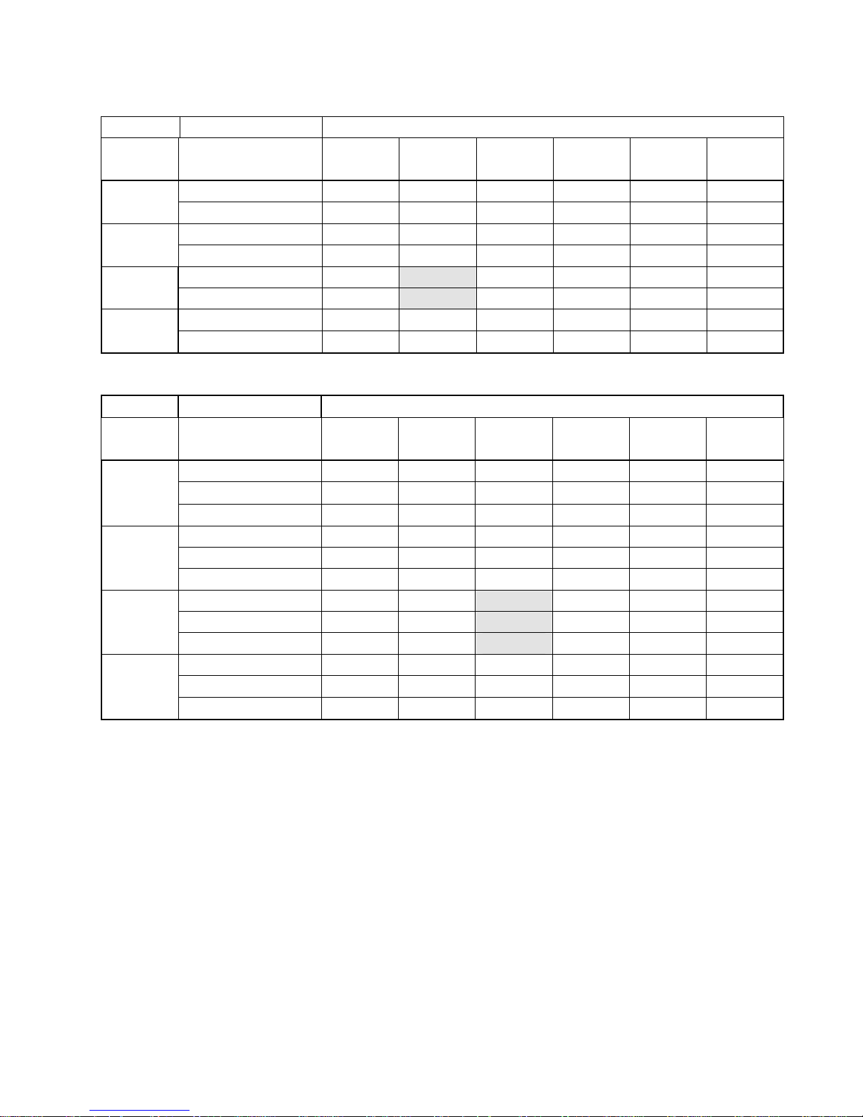
Heating mode
OUTDOOR CONDITIONS
Indoor Conditions
Pressure
12ºC D
11ºC W
7ºC D
6ºC W
0ºC D
-1ºC W
-4ºC D
-6ºC W
-7ºC D
-9ºC W
-15ºC D
-xºC W
15ºC
Pressure
( kg/cm2 )
24.0 23.0 21.5 21.0 20..5 /
18ºC
Pressure
( kg/cm2 )
24.6 23.5 23.0 22.6 20.8 /
20ºC
Pressure
( kg/cm2 )
25.0 23.8 24.0 23.0 21.0 /
22ºC
Pressure
( kg/cm2 )
25.3 24.6 24.5 23.8 21.7 /
251
Page 10
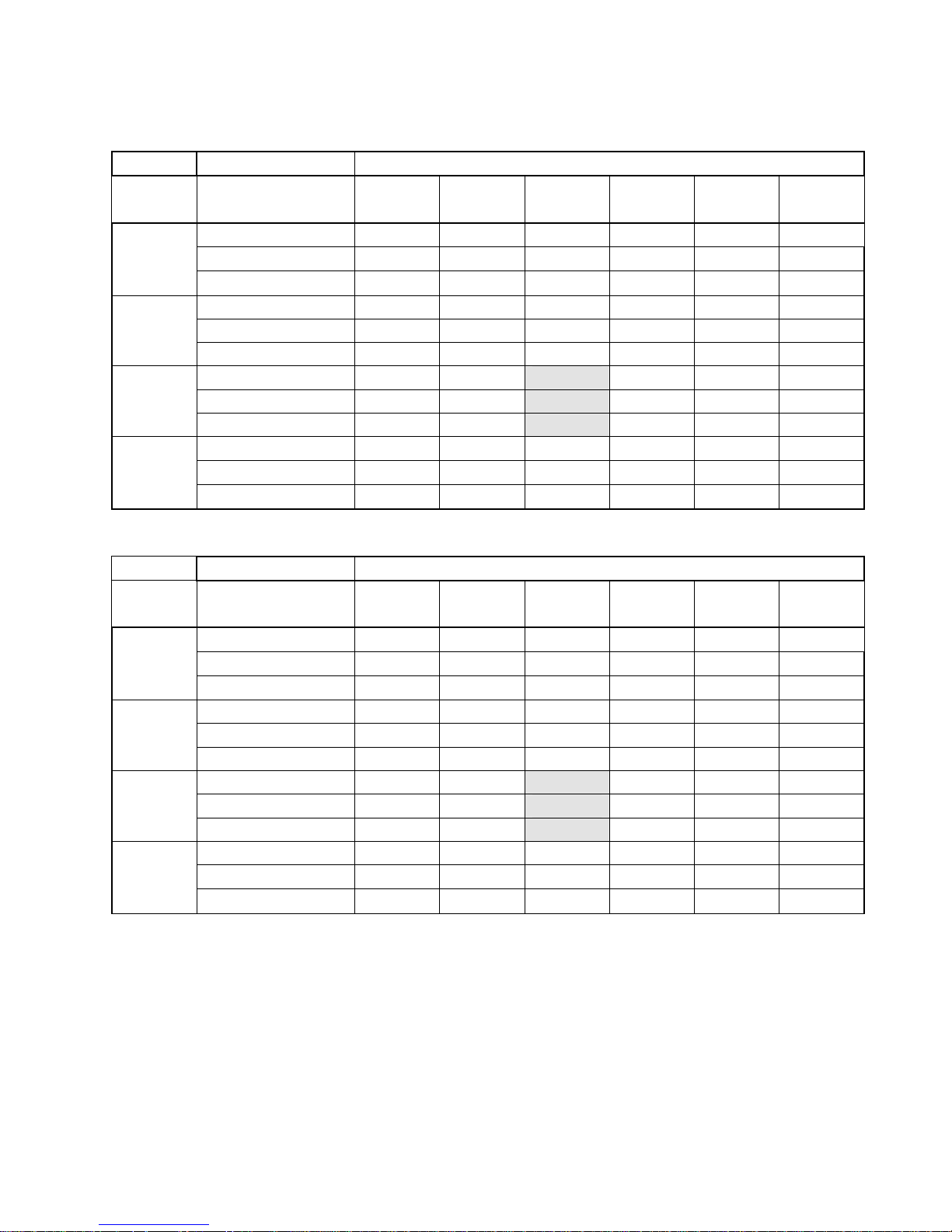
5.3 MSH-09CRN1
Cooling mode Outdoor temperature (Dry bulb temp)
Indoor Conditions
Pressure 25ºC 30ºC 35ºC 40ºC 45ºC 50ºC
21ºC D
15ºC W
Pressure
( kg/cm2 )
7.8 8.1 8.4 9.0 9.3 10.0
24ºC D
17ºC W
Pressure
( kg/cm2 )
7.9 8.2 8.7 9.0 9.5 10.1
27ºC D
19ºC W
Pressure
( kg/cm2 )
8.0 8.5 9.2 9.9 10.2 10.8
32ºC D
23ºC W
Pressure
( kg/cm2 )
8.8 9.1 9.2 10.0 10.5 11.2
5.4 MSH-09HRN1
Cooling mode Outdoor temperature (Dry bulb temp)
Indoor Conditions
Pressure 25ºC 30ºC 35ºC 40ºC 45ºC 50ºC
21ºC D
15ºC W
Pressure
( kg/cm2 )
7.8 8.1 8.4 9.0 9.3 10.0
24ºC D
17ºC W
Pressure
( kg/cm2 )
7.9 8.2 8.7 9.0 9.5 10.1
27ºC D
19ºC W
Pressure
( kg/cm2 )
8.0 8.5 9.2 9.9 10.2 10.8
32ºC D
23ºC W
Pressure
( kg/cm2 )
8.8 9.1 9.2 10.0 10.5 11.2
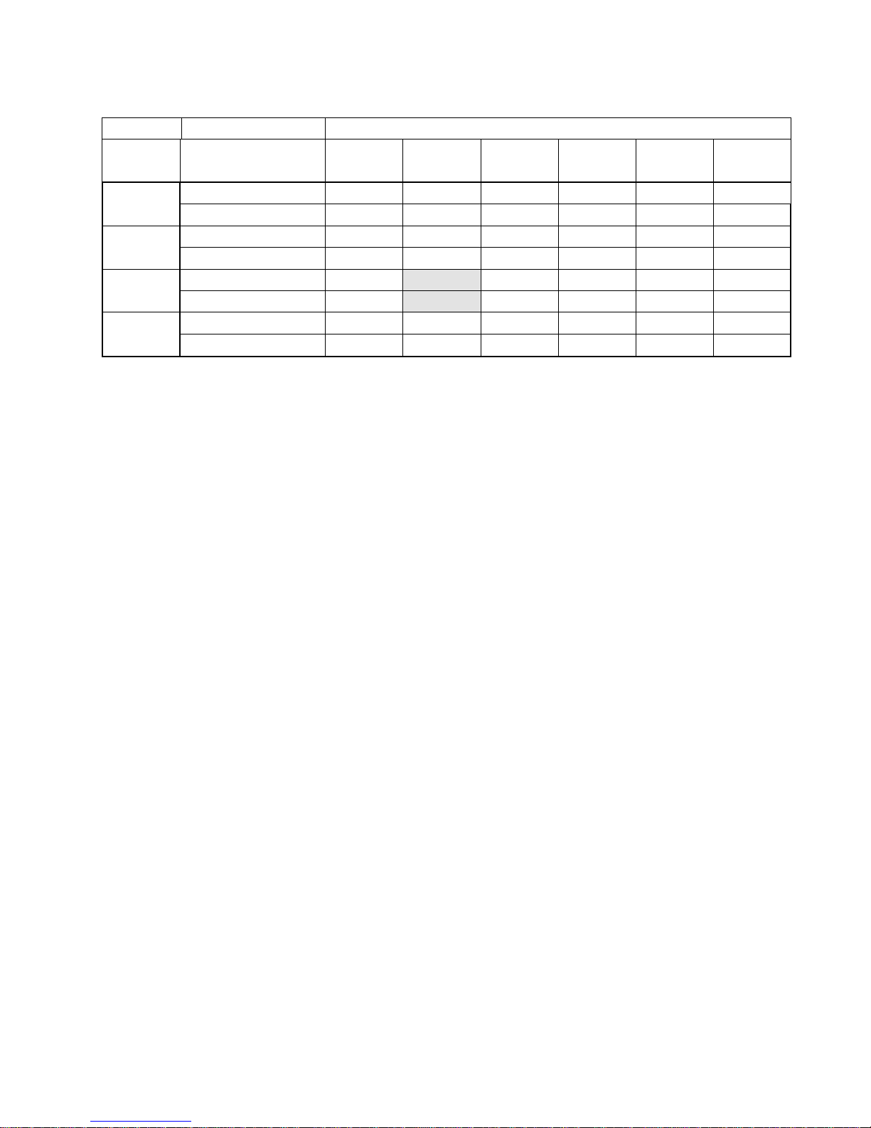
Heating mode
OUTDOOR CONDITIONS
Indoor Conditions
Pressure
12ºC D
11ºC W
7ºC D
6ºC W
0ºC D
-1ºC W
-4ºC D
-6ºC W
-7ºC D
-9ºC W
-15ºC D
-xºC W
15ºC
Pressure
(
kg/cm2 )
26.5 25.0 22.0 21.5 20.5 /
18ºC
Pressure
(
kg/cm2 )
27.0 26.0 23.5 22.5 20.8 /
20ºC
Pressure
(
kg/cm2 )
27.5 26.5 25.0 23.0 21.0 /
22ºC
Pressure
2
28.5 27.0 25.5 23.9 21.5 /
252
Page 11
5.5 MSH-12CRN1
Cooling mode
Outdoor temperature (Dry bulb temp)
Indoor Conditions
Pressure 25ºC 30ºC 35ºC 40ºC 45ºC 50ºC
21ºC D
15ºC W
Pressure
( kg/cm
2
)
8.4 8.5 8.8 8.9 9.4 9.9
24ºC D
17ºC W
Pressure
( kg/cm
2
)
8.6 8.8 9.2 9.4 10.0 10.4
27ºC D
19ºC W
Pressure
( kg/cm
2
)
8.8 9.2 9.4 9.8 10.3 10.9
32ºC D
23ºC W
Pressure
( kg/cm
2
)
9.2 9.6 9.9 10.4 10.8 11.2
5.6 MSH-12HRN1
Cooling mode Outdoor temperature (Dry bulb temp)
Indoor Conditions
Pressure 25ºC 30ºC 35ºC 40ºC 45ºC 50ºC
21ºC D
15ºC W
Pressure
( kg/cm
2
)
8.4 8.5 8.8 8.9 9.4 9.9
24ºC D
17ºC W
Pressure
( kg/cm
2
)
8.6 8.8 9.2 9.4 10.0 10.4
27ºC D
19ºC W
Pressure
( kg/cm
2
)
8.8 9.2 9.4 9.8 10.3 10.9
32ºC D
23ºC W
Pressure
( kg/cm2 )
9.2 9.6 9.9 10.4 10.8 11.2
Heating mode
OUTDOOR CONDITIONS
Indoor Conditions
Pressure
12ºC D
11ºC W
7ºC D
6ºC W
0ºC D
-1ºC W
-4ºC D
-6ºC W
-7ºC D
-9ºC W
-15ºC D
-xºC W
15ºC
Pressure
(
kg/cm2 )
27.4 25.9 22.2 21.4 20.0 /
18ºC
Pressure
(
kg/cm2 )
29.8 27.2 23.8 22.0 21.1 /
20ºC
Pressure
(
kg/cm2 )
30.2 29.1 24.2 23.6 22.1 /
22ºC
Pressure
2
32.4 30.1 25.4 24.0 22.7 /
253
Page 12
6. Capacity table
6.1 MSH-07CRN1
SUMMER OUTDOOR TEMPERATURE DRY
Indoor
Conditions
25ºC 30ºC 35ºC 40ºC 45ºC 50ºC
Total capacity kW 2.06 1.95 1.75 1.51 1.58 1.41
Sensitive capacity kW 1.52 1.37 1.39 1.32 1.19 1.07
21ºC D
15ºC W
Input kW. 0.53 0.58 0.62 0.63 0.78 0.80
Total capacity kW 2.14 2.05 1.96 1.72 1.73 1.52
Sensitive capacity kW 1.61 1.46 1.45 1.54 1.23 1.15
24ºC D
17ºC W
Input kW. 0.60 0.60 0.66 0.65 0.78 0.83
Total capacity kW 2.31 2.24
2.10
1.90 1.73 1.67
Sensitive capacity kW 1.78 1.65
1.42
1.43 1.26 1.28
27ºC D
19ºC W
Input kW. 0.55 0.63
0.64
0.70 0.79 0.84
Total capacity kW 2.33 2.33 2.31 2.38 2.15 2.07
Sensitive capacity kW 1.83 1.67 1.65 1.64 1.57 1.53
32ºC D
23ºC W
Input kW. 0.53 0.65 0.69 0.73 0.83 0.88
6.2 MSH-07HRN1
SUMMER OUTDOOR TEMPERATURE DRY
Indoor
Conditions
25ºC 30ºC 35ºC 40ºC 45ºC 50ºC
Total capacity kW 2.04 1.94 1.70 1.61 1.53 1.41
Sensitive capacity kW 1.52 1.41 1.39 1.32 1.19 1.07
21ºC D
15ºC W
Input kW. 0.53 0.58 0.60 0.67 0.73 0.80
Total capacity kW 2.14 2.05 1.93 1.81 1.73 1.51
Sensitive capacity kW 1.61 1.46 1.45 1.54 1.23 1.15
24ºC D
17ºC W
Input kW. 0.54 0.60 0.62 0.70 0.74 0.82
Total capacity kW 2.31 2.24
2.05
1.95 1.70 1.65
Sensitive capacity kW 1.78 1.65
1.54
1.43 1.26 1.28
27ºC D
19ºC W
Input kW. 0.57 0.62
0.64
0.71 0.75 0.83
Total capacity kW 2.33 2.36 2.31 2.25 2.15 2.03
Sensitive capacity kW 1.83 1.67 1.65 1.64 1.57 1.52
32ºC D
23ºC W
Input kW. 0.58 0.64 0.66 0.73 0.80 0.86
254
Page 13
WINTER OUTDOOR CONDITIONS
Indoor
Conditions
12ºC D
11ºC W
7ºC D
6ºC W
4ºC D
3ºC W
0ºC D
-1ºC W
-4ºC D
-6ºC W
-7ºC D
-8ºC W
Capacity kW 3.01 2.73 2.47 1.76 1.65 1.58
15ºC
Input kW. 0.76 0.66 0.60 0.58 0.50 0.45
Capacity kW 2.86 2.64 2.34 1.69 1.53 1.41
18ºC
Input kW. 0.78 0.67 0.62 0.59 0.62 0.47
Capacity kW 2.77
2.49
2.28 1.62 1.59 1.33
20ºC
Input kW. 0.81
0.69
0.64 0.59 0.53 0.48
Capacity kW 2.61 2.43 2.13 1.58 1.26 1.17
22ºC
Input kW. 0.83 0.68 0.65 0.60 0.56 0.51
6.3 MSH-09CRN1
SUMMER OUTDOOR TEMPERATURE DRY
Indoor
Conditions
25ºC 30ºC 35ºC 40ºC 45ºC 50ºC
Total capacity kW 2.42 2.37 2.23 2.03 1.87 1.75
Sensitive capacity kW 1.72 1.69 1.65 1.53 1.43 1.36
21ºC D
15ºC W
Input kW. 0.72 0.75 0.80 0.84 0.89 0.96
Total capacity kW 0.65 2.55 2.45 2.24 2.11 1.98
Sensitive capacity kW 1.83 1.73 1.70 1.63 1.63 1.57
24ºC D
17ºC W
Input kW. 0.70 0.76 0.84 0.88 0.92 1.01
Total capacity kW 2.89 2.80
2.66
2.46 2.25 2.03
Sensitive capacity kW 1.95 1.91
1.83
1.78 1.66 1.63
27ºC D
19ºC W
Input kW. 0.65 0.78
0.82
0.91 0.95 1.02
Total capacity kW 3.01 2.98 2.92 2.83 2.69 2.45
Sensitive capacity kW 2.05 1.88 1.96 1.87 1.87 1.85
32ºC D
23ºC W
Input kW. 0.64 0.80 0.88 0.98 1.03 1.10
255
Page 14

6.4 MSH-09HRN1
SUMMER OUTDOOR TEMPERATURE DRY
Indoor
Conditions
25ºC 30ºC 35ºC 40ºC 45ºC 50ºC
Total capacity kW 2.42 2.41 2.24 2.03 1.87 1.75
Sensitive capacity kW 1.72 1.69 1.65 1.53 1.43 1.36
21ºC D
15ºC W
Input kW. 0.72 0.75 0.80 0.84 0.89 0.97
Total capacity kW 0.65 2.55 2.45 2.24 2.11 1.98
Sensitive capacity kW 1.83 1.73 1.70 1.63 1.63 1.57
24ºC D
17ºC W
Input kW. 0.68 0.76 0.81 0.88 0.93 1.02
Total capacity kW 2.89 2.80
2.63
2.45 2.23 2.05
Sensitive capacity kW 1.99 1.95
1.81
1.78 1.66 1.63
27ºC D
19ºC W
Input kW. 0.65 0.78
0.82
0.92 0.96 1.03
Total capacity kW 3.03 2.98 2.92 2.83 2.69 2.46
Sensitive capacity kW 2.05 1.88 1.96 1.87 1.87 1.85
32ºC D
23ºC W
Input kW. 0.65 0.80 0.86 0.95 0.99 1.08
WINTER OUTDOOR CONDITIONS
Indoor
Conditions
12ºC D
11ºC W
7ºC D
6ºC W
4ºC D
3ºC W
0ºC D
-1ºC W
-4ºC D
-6ºC W
-7ºC D
-8ºC W
Capacity kW 3.75 3.38 3.02 1.97 1.59 1.52
15ºC
Input kW. 0.97 0.84 0.73 0.65 0.62 0.63
Capacity kW 3.52 3.26 2.94 1.84 1.60 1.49
18ºC
Input kW. 0.98 0.86 0.78 0.70 0.65 0.68
Capacity kW 3.45
3.22
2.85 1.82 1.56 1.50
20ºC
Input kW. 1.02
0.89
0.80 0.74 0.68 0.67
Capacity kW 3.18 3.13 2.72 1.73 1.58 1.42
22ºC
Input kW. 1.06 0.93 0.82 0.77 0.71 0.65
256
Page 15
6.5 MSH-12CRN1
SUMMER OUTDOOR TEMPERATURE DRY
Indoor
Conditions
25ºC 30ºC 35ºC 40ºC 45ºC 50ºC
Total capacity kW 3304 3198 3921 2856 2787 2684
Sensitive capacity kW 2607 2497 2411 2304 2242 2111
21ºC D
15ºC W
Input kW. 907 1006 1096 1184 1259 1457
Total capacity kW 3683 3511 3339 3166 3066 2960
Sensitive capacity kW 2938 2790 2745 2580 2470 2359
24ºC D
17ºC W
Input kW. 926 1035 1127 1230 1278 1380
Total capacity kW 3896 3718
3646
3387 3235 3232
Sensitive capacity kW 3076 2938
2856
2690 2580 2470
27ºC D
19ºC W
Input kW. 943 1058
1120
1265 1322 1437
Total capacity kW 4199 4009 3850 3614 3541 3370
Sensitive capacity kW 3098 2990 2745 2607 2552
32ºC D
23ºC W
Input kW. 977 1090 1190 1310 1368 1495
2900
6.6 MSH-12HRN1
SUMMER OUTDOOR TEMPERATURE DRY
Indoor
Conditions
25ºC 30ºC 35ºC 40ºC 45ºC 50ºC
Total capacity kW 3276 3187 3105 2821 2746 2621
Sensitive capacity kW 2567 2457 2413 2287 2210 2087
21ºC D
15ºC W
Input kW. 890 1010 1082 1188 1243 1337
Total capacity kW 3663 3503 3315 3148 3076 2932
Sensitive capacity kW 2918 2766 2725 2557 2453 2334
24ºC D
17ºC W
Input kW. 915 1033 1121 1228 1278 1367
Total capacity kW 3860 3700
3626
3371 3215 3125
Sensitive capacity kW 3039 2913
2832
2645 2567 2419
27ºC D
19ºC W
Input kW. 944 1048
1120
1253 1312 1426
Total capacity kW 4215 4100 3845 3601 3501 3313
Sensitive capacity kW 3120 2939 2891 2715 2589 2503
32ºC D
23ºC W
Input kW. 969 1088 1189 1302 1349 1455
257
Page 16
WINTER OUTDOOR CONDITIONS
Indoor
Conditions
12ºC D
11ºC W
7ºC D
6ºC W
4ºC D
3ºC W
0ºC D
-1ºC W
-4ºC D
-6ºC W
-7ºC D
-8ºC W
Capacity kW 4446 4264 4132 3838 3335 305
15ºC
Input kW. 1141 1106 1059 1035 895 812
Capacity kW 4380 4248 3954 3761 3258 2948
18ºC
Input kW. 1188 1153 1142 1082 953 918
Capacity kW 4261
4153
3877 3683 3189 2871
20ºC
Input kW. 1224
1180
1129 1082 976 941
Capacity kW 4106 3989 3761 3567 3045 2876
22ºC
Input kW. 1259 1212 1153 1106 1000 836
258
Page 17
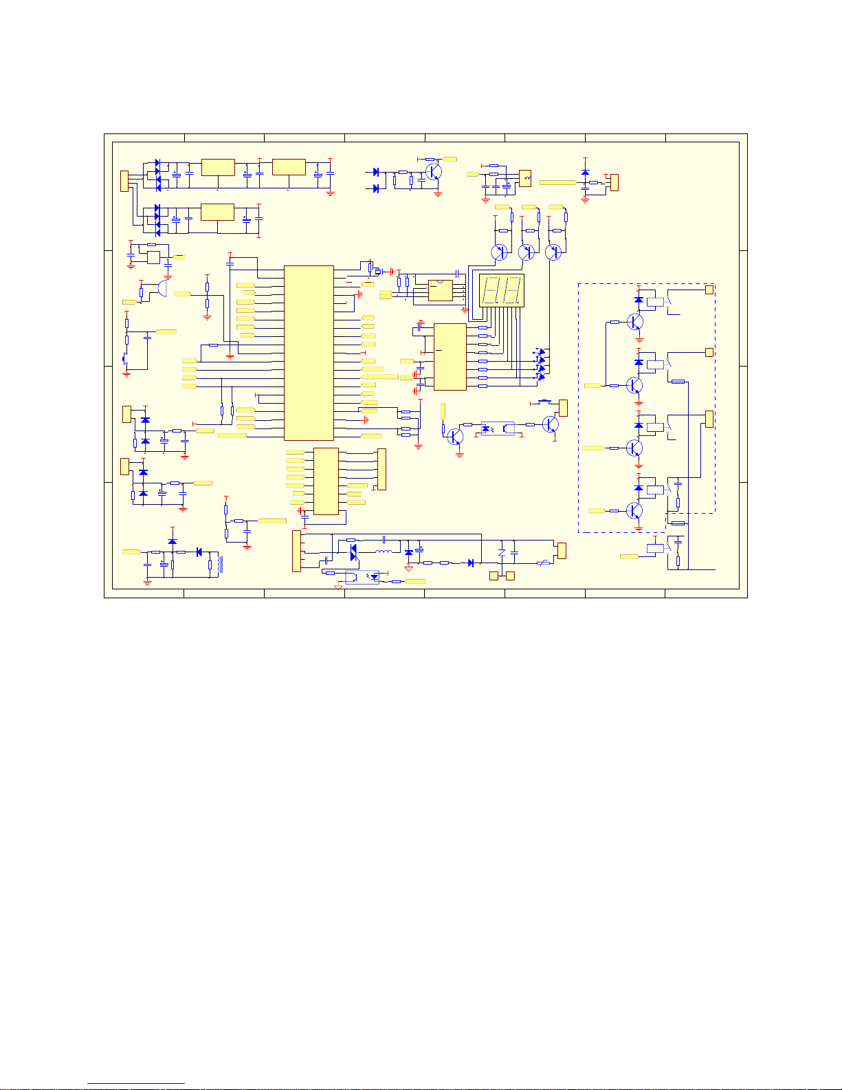
7. Schematic diagram and wiring diagram
7.1 Schematic diagram
1 2 3 4 5 6 78
A
B
C
D
8
7654321
D
C
B
A
C1
104
Vin
1
GND
2
Vout
3
IC3 78 05
E3
470uF/16V
E1
2200uF/25V
C4
104
D4
D3
D2
D1
Vin
1
GND
2
Vout
3
IC1 781 2
E2
1000uF/16V
C3
104
X1
4M
R7
1M
A0
1
A1
2
A2
3
GND
4
SDA
5
SCL
6
WC
7
VCC
8
IC2
24C04
C2
104
R2
10K
R1
10K
C5
104
R412K
1
2
3
IC5 KIA7 042
BUZ1
BUZZER1
R5
1K
R27
2K
Q3
9014
E4
10uF/16V
R8
8.1K/1%
C6
104
R10 2K
D6
IN4148
D5
IN4148
1
2
CN2
T1_roo m
E5
10uF/16V
R9
8.1K/1%
C7
104
R11 2K
D8
IN41 48
D7
IN41 48
1
2
CN3
T2_I.p ipe
CT1
0057h
D10
1N4148
R14
1.4K/1%
R6
1K/1%
R13
16K
E6
10uF/16V
D9
1N4148
R12 2K
C8
104
Q2
9014
R15
12K
C9
104
D11 1N4148
D12 1N4148
R16 12K
R17
12K
R18 10K
E7
10uF/16V
C10
102
R19 150
R20 1K
C11
104
R215.1K
D13
IN41 48
C12
103
+5V
1
2
3
CN4
FAN_BACK
REC
V
GND
REC1
RECEIVER_V
JR7
10K
C13
104
R23 2K
C14
1.2uF/450V
IC6 PC8 17
T1
T2
G
TR1
BT131
L2
?
C15
333
R242K
R26
1K
E9
470uF/25V
R28
11K/2W
Z1
12V
D15
IN4 007
R29
11K/2W
R25 51/1W
IN1
1
IN2
2
IN3
3
IN4
4
IN5
5
IN6
6
IN7
7
VSS
8
VDD
9
OUT7
10
OUT6
11
OUT5
12
OUT4
13
OUT3
14
OUT2
15
OUT1
16
IC7
UJN2003
C19
104
1
2
3
4
5
CN12
SWING
RY2
RELAY-SPST
D21
IN4148
R33
2K
Q5
9014
RY3
RELAY-SPST
D22
IN4 148
R34
2K
Q6
9014
RY4
RELAY-SPST
D23
IN4148
R35
2K
Q7
9014
RY5
RELAY-SPST
D24
IN4148
C20
333
R36
51/1W
RY6
COMP
C21
333
R37
51/1W
1
CN14
N
SE1
3.15A/250V
FUSE2
10A
1
CN11
N
1
CN10
HEAT_L
1
CN9
HEAT_N
1
2
CN13
ZR1
10D471K
C23
0.1uF/275VAC
1
2
CN15
TRANS_IN
SW1
t
PTC
82RM
R39
5.1K
C22
104
R38
10K
Onl y For Hea t Pump
Dsa
1
Dsb
2
Q0
3
Q1
4
Q2
5
Q3
6
GND
7
CP
8
MR
9
Q4
10
Q5
11
Q6
12
Q7
13
Vcc
14
IC8
74HC164
R60
10K
R59
10K
C24
104
Q8
9012
Q9
9012
Q10
9012
R44
330
R45 330
R46 330
R47 330
R48 330
R49 330
R54 330
R55 330
R41
2K
R42
2K
R43
2K
LED6
自动
LED7
化霜
LED8
定时
+5V
a
b
c
d
e
f
g
h
com1
com2
DIS1
WT4021BG
LED9
运行灯
1
2
3
4
5
CN6
FAN_IN
C25
104
IN40 07* 4
VSS0
1
VDD0
2
P25
3
P26
4
P00
5
P01
6
P02
7
P03
8
P04
9
VSS1
10
P05
11
P50
12
P51
13
P52
14
P53
15
AVDD
16
AVREF
17
AN10
18
AN11
19
AN12
20
AN13
21
AN14
22
AN15
23
AVSS
24
P10
25
P11
26
P30
27
P31
28
P32
29
P33
30
P20
31
VDD1
32
P21
33
P22
34
P23
35
P24
36
Vpp/ IC
37
XT2
38
XT1
39
RESET
40
X2
41
X1
42
IC4
UPD789 166
C26
104
JR1
10K
JR3 10K
JR2
10K
JR5 10K
JR4
10K
C16
102
C17
102
JR6
10K
JR8
10K
JR9
10K
R41
10K
R41
10K
R41
10K
+5V
+5V
R61
2K
Q11
9014
R62
1K
IC9
PC817
SW2
R63
5.1K
Q12
9014
1
2
CN16
C23
104
E10
2200uF/25V
D19
D18
D17
D16
Vin
1
GND
2
Vout
3
IC10 7812
E11
1000uF/16V
C24
104
IN40 07* 4
1
2
3
4
CN1
TRANS
+5V+12V-a
+5V
+5V
+12V
+5V
+5V
+5V
+5V
+5V
+12V-a
+5V
+12V-a
+12V-a
+12V-a
+12V-a
+12V-a
+12V-a
+12V-a
+5V
+5V
+5V
+5V
+12V-a
+5V
+5V
+5V
+5V
+12V-a +12V-b
GNDB
+12V-b
+12V-b
GNDB
SDA
SDA
SCL
SCL
RST
RST
BUZ
BUZ
T1_roo m
T1_roo m
T2_I. pipe
T2_I. pipe
Current
Curre nt
ZERO
ZERO
A
B
B
A
REC
REC
FANSP_FEEDBAC K
FANSP_FEEDBAC K
AUTO_SELECT
AUTO_SELECT
L1
N
FAN_IN '
FAN_IN
STEP_I2
STEP_I1
STEP_I3
STEP_I4
STEP_I2
STEP_I1
STEP_I3
STEP_I4
FAN_IN '
FAN_IN
BUZ '
BUZ '
COMP
COMP
COMP '
COMP '
VALVE
VALVE
FAN_OUT
FAN_OUT
HEAT
HEAT
L(POWER_IN PORT)
LOAD_COMP
N
FU
L1
L1
FRESH
LOAD_VALVE
LOAD_FAN OUT
LOAD_HEAT L
LOAD_HEAT N
SW_TEST
SW_TEST
COM1
COM2
COM3SEG1
SEG2
SEG3
SEG4
SEG3
SEG4
COM1 COM2 COM3
COM1
COM2
COM3SEG1
SEG2
SEG3
SEG4
SCL
SDA
T1
T2
CURRENT
AUTO_SELECT SW
STEP_I1
STEP_I2
STEP_I3
STEP_I4
FAN_IN
BUZ
COMP
VALVE
FAN_OUT
ZERO
FANSP
REC
HEAT
FRESH
RST
X2
X1
FRESH
C
D
259
Page 18
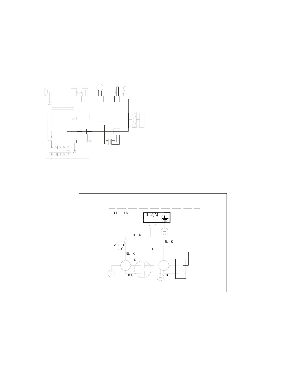
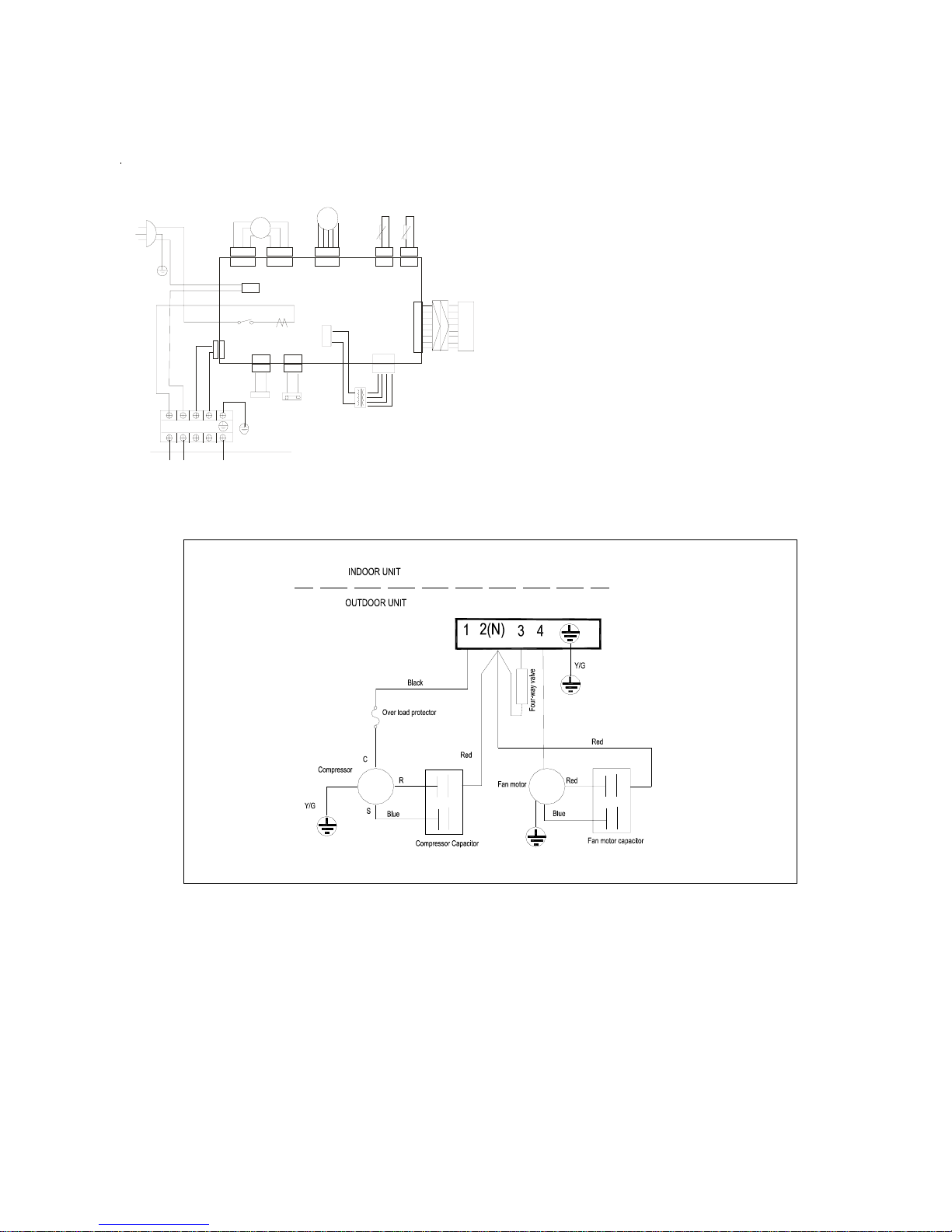
7.2 Wiring diagram
7.2.1 Cooling only
7.2.1.1 MSH-07CRN1, MSH-09CRN1
12
34
5
1
2345
21
2
1
21
2
1
351
35
1
32
1
321
31
1
14
DISPLAY BOARD
CN 6 CN4 CN12 CN2
CN 3
CN11
RE D
BLUE
BL ACK
CN1
TR ANSF ORME R
CN5
P
O
WER
S
U
P
P
L
Y
IND
O
O
R
M
O
T
O
R
S
T
EP
MOTOR
ROOM TEMPERATURE
SENSOR
PIPE TEMPERATURE
SENSOR
JX1
INDOOR UNIT
TO OUTDOOR UNIT
Y/G
1
2(N)
34
BROWN
Y/G
COM
P
RESSOR
REL
A
Y
CN15
8 7 6 5 4 3 21
4
CN7 CN16
21
2
1
21
21
SW2
WAT ER SWITCH
1 2(N)
COMPRESSOR
CAPACITOR
RE
D
OUTDOOR
U
N
IT
OVERLOAD
RELA
Y
Y&G
COMPRESSOR
S
C
BLU
E
R
B
LACK
RE
D
B
LACK
INDOOR UNIT
FAN
CAPACITOR
RED
Y&G
FAN
MOTOR
Y&G
B
L
UE
B
LACK
RED
260
Page 19
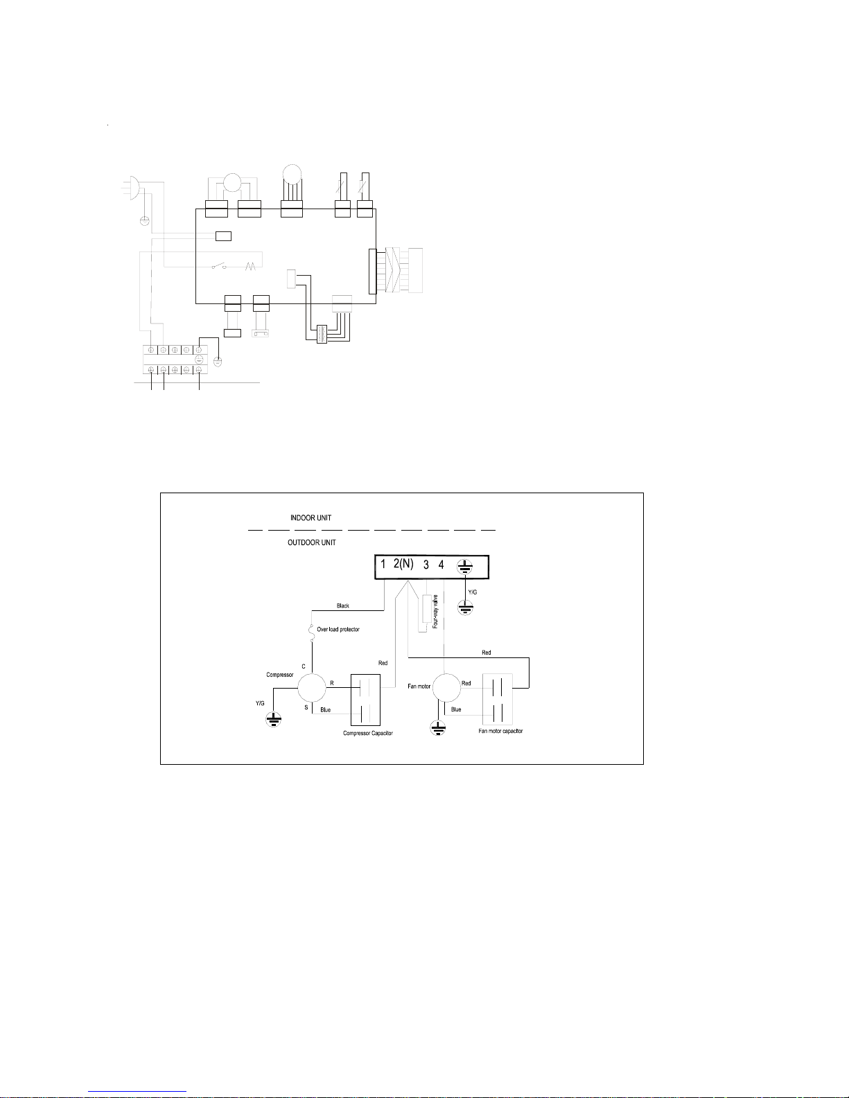
7.2.1.2 MSH-12CRN1
12
34
5
1
2345
21
2
1
21
2
1
351
35
1
32
1
321
31
1
14
DISPLAY BOARD
CN 6
CN4
CN12 CN2
CN 3
CN11
RE D
BLUE
BL ACK
CN1
TR ANSF ORME R
CN5
PO
WER
SU
PP LY
INDOOR MOTOR
STEP MOTOR
ROOM TEMPERATURE
SENSOR
PIPE TEMPERATURE
SENSOR
JX1
INDOOR UNIT
TO OUTDOOR UNIT
Y/G
1
2(N)
34
BROWN
Y/G
COMPRESSOR RELAY
CN15
8 7 6 5 4 3 21
4
CN7 CN16
21
2
1
21
21
SW2
WAT ER SWITCH
261
Page 20
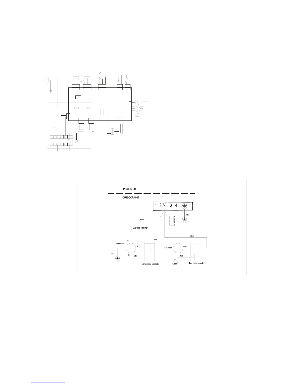
7.2.2 Heating/cooling
7.2.2.1 MSH-07HRN1, MSH-09HRN1
12
34
5
1
2345
21
2
1
21
2
1
351
35
1
32
1
321
2
1
14
DISPLAY BOARD
CN 6
CN4
CN12 CN2
CN 3
CN11
RE D
BLUE
BL ACK
CN1
TR ANSF ORME R
CN5
PO
WER
SU
PP LY
INDOOR MOTOR
STEP MOTOR
ROOM TEMPERATURE
SENSOR
PIPE TEMPERATURE
SENSOR
JX1
INDOOR UNIT
TO OUTDOOR UNIT
Y/G
1
2(N)
34
BROWN
Y/G
COMPRESSOR RELAY
CN15
8 7 6 5 4 3 21
4
CN7 CN16
21
2
1
21
21
SW2
WAT ER SWITCH
CN13
1 21
121
1
262
Page 21
7.2.2.2 MSH-12HRN1
12
34
5
1
2345
21
2
1
21
2
1
351
35
1
32
1
321
2
1
14
DISPLAY BOARD
CN 6
CN4
CN12 CN2
CN 3
CN11
RE D
BLUE
BL ACK
CN1
TR ANSF ORME R
CN5
PO
WER
SU
PP LY
INDOOR MOTOR
STEP MOTOR
ROOM TEMPERATURE
SENSOR
PIPE TEMPERATURE
SENSOR
JX1
INDOOR UNIT
TO OUTDOOR UNIT
Y/G
1
2(N)
34
BROWN
Y/G
COMPRESSOR RELAY
CN15
8 7 6 5 4 3 21
4
CN7 CN16
21
2
1
21
21
SW2
WAT ER SWITCH
CN13
1 21
121
1
263
Page 22

8 Electronic function
8.1 Electric Control working environment
8.1.1 input voltage: 175~253V
8.1.2 Input power frequency:50Hz
8.1.3 Ambient temperature: -7°C~+43°C
8.1.4 Indoor fan normal working amp is less than 1A,
8.1.5 Outdoor fan. Normal working amp is less than 1.5A
8.1.6 Four-way valve normal working amp is less than 1A.
8.1.7 Swing motor: DC12V.
8.1.8 Compressor: single-phase power supply. Its normal working amp is less than 15A
8.2 Proper symbols and their meanings:
TA: Indoor ambient temperature
TE: Indoor evaporator temperature
TS: Setting temperature through the remote controller
I
3sec
: Self-protection amp of compressor, continue three seconds until turns off the compressor.
I
5MIN
: Self-protection amp of compressor, continue five minutes until turns off the compressor.
I
FAN
: Self-protection amp of outdoor fan/indoor fans when they change from higher wind to lower wind.
I
RESTORE
: Amp self-protection return value
TH
DEFROST
: High wind, defrosting temperature difference
TM
DEFROST
: Middle wind, defrosting temperature difference
TL
DEFROST
: Low wind, defrosting temperature difference
TE1: Anti-cold wind, from Fan Off to Breeze temperature
TE2: Anti-cold wind, from Breeze to Setting Fan Speed temperature
TE3: Anti-cold wind, from Setting Fan Speed to Breeze temperature
TE4: Anti-cold wind, from Breeze to Fan Off temperature
TE5: Evaporator low temperature protection entering temperature
TE6: Evaporator low temperature protection restoring temperature
TE7: Evaporator high temperature protection, compressor off temperature
TE8: Evaporator high temperature protection, fan off temperature
TE9: Evaporator high temperature protection, restoring temperature
8.3 Functions
Remote receiving
Testing and forced running
Position set for indoor unit wind vane
LED displaying and alarm
On or off Timer
Protection for the compressor
Current protection
High temperature protection of indoor heat exchanger at heating mode
Auto defrosting and heating recovery at heating mode
Anti cold air at heating mode
Anti frozen at cooling mode
264
Page 23
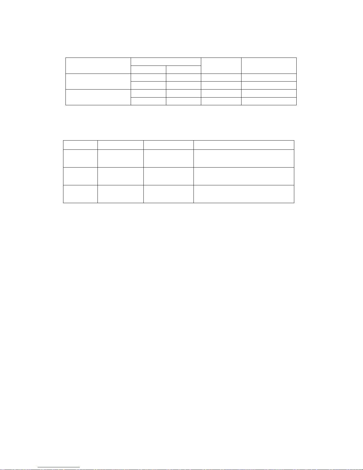
8.4 Protection
8.4.1 3 minutes delay at restart for compressor.
8.4.2 Sensor protection at open circuit and breaking disconnection
8.4.3 Fan Speed is out of control. When Indoor Fan Speed is too high(higher than High Fan+300RPM)or
too low(lower than 400RPM), the unit stops and LED displays failure information and can’t returns to
normal operation automatically.
8.4.4 Cross Zero signal error warning. If there is no Cross Zero signals in 4 minutes, the unit stops and LED
displays failure information and can’t returns to normal operation automatically.
8.4.5 The current protection of the compressor
Condition Indoor fan Compressor Outdoor fan Remark
I< I
RESTORE
On On On
On On Off Heating mode I
RESTORE
<I< I
FAN
Low speed On On Cooling mode
I
FAN
<I<I
5MIN
Off Off After 5 Minutes
Current up
I
5MIN
<I< I
3SEC
Off Off After 3 Seconds
I
5MIN
<I< I
3SEC
Off Off After 3 Seconds
I
FAN
<I<I
5MIN
Off Off After 5 Minutes
On On Off Heating mode I
RESTORE
<I< I
FAN
Low speed On On Cooling mode
Current down
I< I
RESTORE
On On On
If compressor turns off for continuously 4 times due to current protection in 5 minutes from
Compressor On, the unit stops and LED displays failure information and can’t returns to normal
operation automatically.
8.5 Fan-only mode
Fan speed is high/mid/low/ Auto
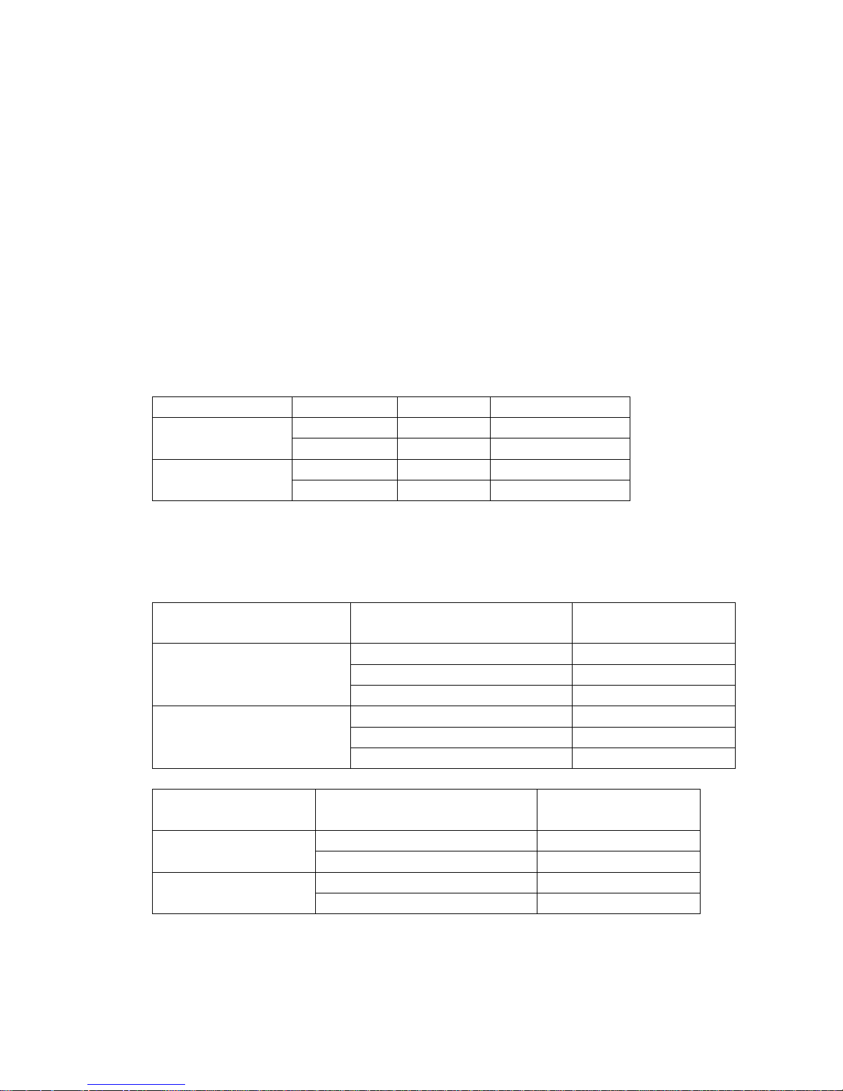
8.6 Cooling mode
The 4-way valve is closed at cooling mode.
The action of the compressor and the outdoor fan:
Condition
T=Indoor Temp.
Ts=Setting Temp.
Compressor Outdoor fan
T> Ts+1 On On Room temp. up
T<Ts+1 Off Off
T> Ts On On Room temp. down
T<Ts Off Off
Auto fan at cooling mode:
Condition
T=Indoor Temp.-Setting Temp.
Indoor fan speed
T<4℃ Low
4℃<T<5℃ Med.
Room temp. up
T>5℃ High
T> 4℃ High
1<T<℃ 4℃ Med.
Room temp. down
T<1℃ Low
265
Page 24
Anti-freezing control to indoor evaporator at cooling mode( T: evaporator temp. )
Condition
Temp. Time
Compressor Outdoor fan
T> TE6 On On
Evaporator Temp. up
T< TE6 >5 Minutes Off Off
T> TE5 On On
Evaporator Temp. down
T< TE5 >5 Minutes Off Off
8.7 Dehumidifying mode
8.7.1 The 4-way valve is off in dehumidifying mode
8.7.2 Compressor and Indoor Fan actions in dehumidifying mode
NO Conditions Indoor Fan Compressor and Outdoor Fan
1 TA ≥ TS+2
LOW
BREEZE
ON 6minutes
OFF 4minutes
2 TS ≤TA< TS +2
LOW
BREEZE
ON 5minutes
OFF 5minutes
3 TA < TS
LOW
BREEZE
ON 4minutes
OFF 6minutes
Repeat on and off cycle.
266
Page 25
8.7.3 Low room temperature protection:
When room temperature decreases to below 10℃, compressor and outdoor fan will stop(indoor fan
is Breeze). Dehumidifying operation will be resumed when room temperature restores to over 13℃.
8.7.4 At dehumidifying mode, the anti-freezing function of the indoor heat exchanger is the same as that
of cooling mode.
8.7.5 At dehumidifying mode, the action of fans of indoor is the same as that of air-only mode.
8.8 Heating mode
8.8.1 Generally, the 4-way valve is open in heating mode, but it is closed in defrosting mode. 4-way valve
must delay 2 minutes compared with compressor if the compressor changed into non-heating mode
or turned off. 4-way valve doesn't delay in dehumidifying mode.
8.8.2 Generally, the outdoor fan is turned off with the on-off action of compressor in heating mode, except
for the defrosting mode or the end of defrost.
8.8.3 Action of compressor and outdoor fan motor at heating mode: compressor must run for 7 minutes
after starting and then judge temperature. Meanwhile other protections are still valid.
Condition Compressor Outdoor fan
T> Ts+3 Off Off Room temp. up
T<Ts+3 On On
T< Ts+2 On On Room temp. down
T>Ts+2 Off Off
8.8.4 Indoor Fan actions at heating mode
Indoor Fan can be set at HIGH/MID/LOW/AUTO by using a remote controller, but Anti-cold wind
function prevails.
Anti-cold wind control function at heating mode
Condition
T= Indoor exchanger temp.
Indoor fan speed
T<TE1 Off
TE1<T<TE2 Breeze
Indoor exchanger temp. up
T>TE2 Setting fan speed
T> TE3 Setting fan speed
TE3<T<TE4 Breeze
Indoor exchanger temp. down
T<TE4 Off
8.8.5 Auto wind at heating mode
Condition
T=Indoor Temp.-Setting Temp.
Indoor fan speed
T<2℃ High Room temp. up
T>2℃ Med.
T> 0℃ Med. Room temp. down
T<0℃ High
267
Page 26
8.8.6 Indoor evaporator high-temperature protection at heating mode
Condition
T= Indoor exchanger temp.
Compressor Outdoor fan
T<TE8 On On
TE8<T<TE7 On Off
Indoor exchanger temp. up
T>TE7 Off Off
T>TE9 Off Off Indoor exchanger temp. down
T<TE9 On On
8.8.7. The louver opens to Standard Angle ANGLHEAT when power is on for the first time
8.9 Defrosting operation (Available for heating only).
8.9.1 Defrosting condition: Defrosting starts when either of the following ①&②:
① A and B are satisfied:
A: The compressor keeps running for 40 minutes or more.
B: The temperature difference of evaporator and room temperature meets one of the following:
℃
Temp. of evaporator---room temp.
Fan speed is high ≤TH
DEFROST
Fan speed is mid ≤TM
DEFROST
Fan speed is low ≤TL
DEFROST
Breeze Meet only if it is Breeze
② Calculate from the end of latest defrost, evaporator high temp. protection only closes outdoor fan
with the compressor still running. Add up to 90 minutes.
8.9.2 Defrosting time
If the temp. difference condition ① is satisfied for less than 40 minutes, this can be regarded as
severe frosting. The defrosting time is 10 minutes.
If the temp. difference condition ② is satisfied for more than 40 minutes, the defrosting time is 6
minutes.
If the temp. difference condition ① is satisfied out of 40 minutes, generally the defrosting time is 6
minutes, after three continuous 6-minute defrost, the fourth should be 10 minutes defrost. The
circulation is as following:
→7.5-minute defrost → 7.5-minute defrost→7.5-minute defrost→10-minute defrost→
8.9.3 Ending condition of defrosting
If one of following conditions is satisfied, end the defrost and turn into heating mode:
A. The defrost time has reached to 7.5 or 10 minutes.
B. The compressor current has reached to I
DEFROST
or above, I
DEROST
differs in different models.
268
Page 27
8.9.4 Defrosting Actions:
Defrost 10or 6minutes
45S 25S
Compressor
4-way Valve 23S
40S
Outdoor Fan
Indoor Fan
10S
8.10 Automatic operation mode
8.10.1 The air conditioner automatically selects one of the following operation modes: cooling, heating or
fan only according to the temp. difference between room temp. (TA) and set temp. (TS).
TA—TS Operation mode
TA—TS>2℃ Cooling
-1 ≤TA℃ -TS≤+2℃ Fan-only
TA-TS<-1℃ Heating (air-only for cooling only type)
8.10.2 The indoor fan blows automatically in corresponding selected mode.
8.10.3 The motion of indoor fan’s blade should accord with the selected operation mode.
8.10.4 One mode should be carried out for at least 15 minutes once selected. If the compressor cannot
start for 15 minutes, reselect the operation mode according to the room temp. and set temp., or
reselect when the set temp. varies.
8.11 Forced cooling function
8.11.1 Select forced cooling function with the forced cooling button or the switch.
8.11.2 The compressor is unconditionally turned on, after 30 minutes cooling operation whose fan mode is
set as low, the A/C operates at the DRY mode with a set temp. of 24℃.
8.11.3 All protections of remote control cooling are available at forced cooling operation.
8.12 Forced Auto function
Select forced auto function with the forced auto button or the switch.
In forced auto status the A/C operates at remote control mode with a set temp. of 24℃.
8.13 Timer Function
8.14 Economic Running
8.14.1 The economic running function is available at cooling, heating or auto mode.
8.14.2 Cooling:
The set temperature rise 1℃ per hour. Two hours later, the set temperature will maintain as a
269
Page 28

constant and the fan speed is kept at low speed.
8.14.3 Heating:
The set temperature decrease 1℃ per hour. Two hours later, the set temperature will maintain as a
constant and the air circulation is kept at low speed (Cold air proof function takes precedence over
all).
8.14.4 Auto:
The economic running function operates in accordance with selected running mode by auto mode.
8.15 Auto restart function
In case of a sudden power failure, this function automatically sets the unit to previous settings before
the power failure when power returns.
270
Page 29
8.16 Models and Parameters
Model MSH-07CRN2 MSH-07HRN2 MSH-09CRN2 MSH-09HRN2 MSH-12CRN2 MSH-12HRN2
I3SEC 7.5A 7.5A 10.0
A
10.0
A
12.0A 12.0
A
I5MIN 6.2A 6.2A 7.5
A
7.5
A
8.5A 8.5
A
IFAN 5.2A 5.2A 5.5
A
5.5
A
7.5A 7.5
A
IRESTORE 4.2A 4.2A 4.5
A
4.5
A
6.5A 6.5
A
IDEFROST 3.2A 3.5
A
5.0
A
TE1 28℃ 28℃ 34℃
TE2 32℃ 32℃ 37℃
TE3 30℃ 30℃ 33℃
TE4 26℃ 26℃ 22℃
TE5 4℃ 4℃ 4℃ 4℃ 3℃ 3℃
TE6 10℃ 10℃ 10℃ 10℃ 10℃ 10℃
TE7 60℃ 60℃ 63℃
TE8 53℃ 53℃ 53℃
TE9 50℃ 50℃ 50℃
ANGLCOOL 200° 200° 200° 200° 155° 155°
ANGLHEAT 0° 0° 10°
ANGLOFF 124° 124° 124° 124° 124° 124°
TH
17°C 17°C 20°C
TM
18°C 18°C 23°C
TL
19°C 19°C 26°C
271
Page 30
9.Troubleshooting
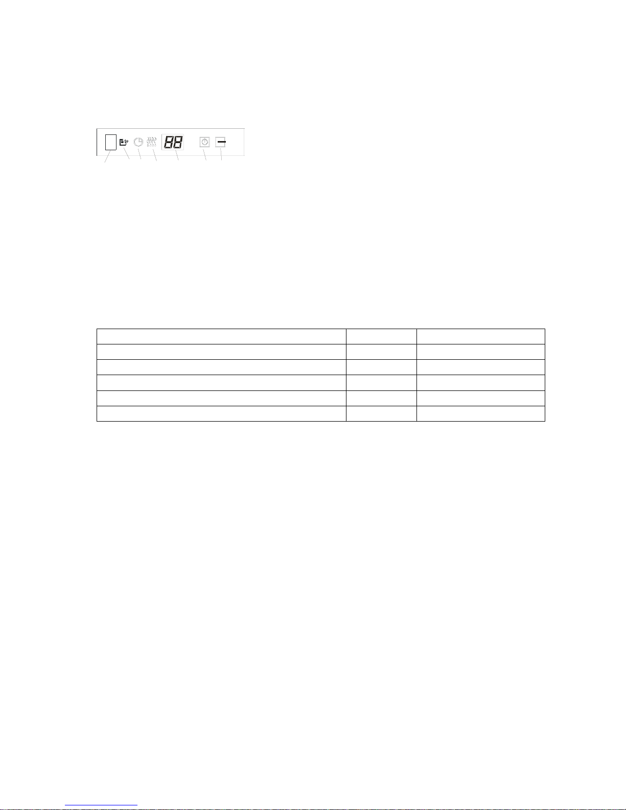
9.1 Display board
1
2
3
4
5
6
Infrared Signal
Recei ver
1: AUTO indicator
2: TIMER indicator
3: PRE.-DEF. Indicator
4: OPERATION indicator
5: SLEEP indicator
9.2 For all heat pump model
Failure phenomenon Operation lamp Timer lamp
Indoor fan speed has been out of control for over 1 minute ☆ X
Indoor room temp. or evaporator sensor is open circuit or short circuit ☆ On
Over current protection of the compressor occurs 4 times X ☆
EEROM error On ☆
No over-zero signal ☆ ☆
r Extinguish
☆ Flash at 5Hz
272
Page 31

☆
9.3 Diagnostic Chart
9.3.1 After energizing, no indicator is lighted and the air conditioner can’t be operated.
A
fter energizing, the air conditione
r
can’t be operated
Yes
Yes No
No Yes
Yes
No
9.3.2 Resetting phenomenon often occurs during operation. (That is automatically entering to the status when
power is on.)
The reason is that the instantaneous voltage of main chip is less than 4.5V. Check according to the following procedure:
Yes
No Yes
No
Check if AC220V power supply outputs to Indoor PCB.
Check if AC220V exists at the primary coil of transformer.
Indoor PCB is defective
Check if AC14.5V exists at the secondary coil of transformer.
Take off the secondary plug of transformer, and then check i
f
A
C14.5V exists at the secondary coil of transformer.
The transformer is defective. Indoor PCB is defective
A
fter changing indoor fan motor, check if the failure releases.
Indoor PCB is defective
A
fter changing Indoor PCB, check if the failure releases.
Power supply circuit has problems.
Resetting phenomenon often occurs during operation.
273
Page 32

9.3.3 Failure phenomenon
Failure phenomenon Operation lamp Timer lamp
Indoor fan speed has been out of control for over 1 minute ☆ X
Indoor room temp. or evaporator sensor is open circuit or short circuit ☆ On
Over current protection of the compressor occurs 4 times X ☆
EEROM error On ☆
No over-zero signal ☆ ☆
r Extinguish
☆ Flash at 5Hz
9.3.3.1 Operation lamp flashes and Timer lamp off.
Is connector connection good?
Is voltage being applied to the fan motor?
Fan motor is defective
Repair the connector
No Yes
Yes No
Indoor PCB is defective
9.3.3.2 Operation lamp flashes and Timer lamp on.
Is connection to connector good?
Replace the sensor
No
Yes
Repair connector
9.3.3.3 Operation lamp off and Timer lamp flashes
No Yes
Yes No
Indoor PCB is defective
Power supply fault Outdoor unit fault (such as the compressor)
Yes
A
fter changing the main control board, check if the failure releases.
The voltage of power supply is too low (less than 187V)?
Operation lamp off and Timer lamp flashes
9.3.3.4 Operation lamp on and Timer lamp flashes
EEROM error, indoor PCB is defective.
9.3.3.5 Operation lamp flashes, Timer lamp flashes .
This is alarm signal when the main chip can’t detect over-zero signal. When such failure occurs, the main
control board must have fault.
274
Page 33

275
10. Characteristic of temp. sensor
Temp.℃ Resistance KΩ Temp.℃ Resistance KΩ Temp.℃ Resistance KΩ
-10 62.2756 17 14.6181 44 4.3874
-9 58.7079 18 13.918 45 4.2126
-8 56.3694 19 13.2631 46 4.0459
-7 52.2438 20 12.6431 47 3.8867
-6 49.3161 21 12.0561 48 3.7348
-5 46.5725 22 11.5 49 3.5896
-4 44 23 10.9731 50 3.451
-3 41.5878 24 10.4736 51 3.3185
-2 39.8239 25 10 52 3.1918
-1 37.1988 26 9.5507 53 3.0707
0 35.2024 27 9.1245 54 2.959
1 33.3269 28 8.7198 55 2.8442
2 31.5635 29 8.3357 56 2.7382
3 29.9058 30 7.9708 57 2.6368
4 28.3459 31 7.6241 58 2.5397
5 26.8778 32 7.2946 59 2.4468
6 25.4954 33 6.9814 60 2.3577
7 24.1932 34 6.6835 61 2.2725
8 22.5662 35 6.4002 62 2.1907
9 21.8094 36 6.1306 63 2.1124
10 20.7184 37 5.8736 64 2.0373
11 19.6891 38 5.6296 65 1.9653
12 18.7177 39 5.3969 66 1.8963
13 17.8005 40 5.1752 67 1.830
14 16.9341 41 4.9639 68 1.7665
15 16.1156 42 4.7625 69 1.7055
16 15.3418 43 4.5705 70 1.6469
Page 34

228
Multi ECO SERIES
1. Features 229
2. Specification 230
3. Dimensions 231
4. Refrigeration cycle diagram 232
5. Operation limits 233
6. Wiring diagram 234
7. Troubleshooting 236
8. Electronic function 238
Page 35

229
1.Features
1.1 Compact design
1.2 High efficiency and quiet operation
Page 36

230
2.Specification
M
o
de
l M
S3G-30
HRN2 M
S3G
-27HRN2
Power supply Ph-V-Hz 1Ph,220-240V~,50Hz 1Ph,220-240V~,50Hz
Capacity Btu/h 9000x2+12000 9000x2+10000
Input W 1800+1300 1800+1300
Rated current A 8.2+5.8 8.2+5.8
Cooling
EER Btu/w.h 10+9.2 10+9.0
Capacity Btu/h 10000x2+13000 10000x2+13000
Input W 1750+1250 1750+1250
Rated current A 8.0+5.6 8.0+5.6
Heating
COP Btu/w.h 3.4+3.0 3.4+2.8
Moisture Removal L/h 1.0x2 +1.2 1.0x2 +1.2
Max. input consumption W 2200+1800 2200+1800
Max. current A 10.0 +8.2 10.0 +8.2
Starting current A 40+30 40+30
Model PG295X2CS-4KU1; PG295X2CS-4KU1;
Type Rotary /GD Toshiba Rotary / GD Toshiba
Capacity Btu/h 18080; 13650 18080; 13650
Input W 1760; 1310 1760; 1310
Rated A 8.5; 6.1 8.5; 6.1
Thermal protector Internal Internal
Capacitor uF 35uF/440VAC; 35uF/440VAC;
Compressor
Refri
g
erant oil ml 750; 480 750; 480
Model RPG13H RPG13H
Input W 36.5 36.5
Capacitor uF 1.2µF/450V 1.2µF/450V
Indoor fan motor
S
p
eed(hi/mi/lo) r/min 1350 1350
Indoor air flow (Hi/Mi/Lo) m3/h 550 550
Indoor noise level (Hi/Mi/Lo) dB(A
)
38/35/31 38/35/31
Dimension mm 750×250×188 750×250×188
Packing mm 830X336X280 830X336X280
Indoor unit
Net/Gross wei
g
ht K
g
8.5/10 8.5/10
Model YDK50-4G1 YDK50-4G1
Input W 107Wx2 107Wx2
Capacitor uF 4uFx2 4uFx2
Outdoor fan motor
S
p
eed r/min 1150 1150
Outdoor air flow m3/h 1450x2 1450x2
Outdoor noise level dB(A
)
57 57
Dimension(W*H*D) mm 860X830X330
Packing (W*H*D) mm 983X915X425
Outdoor unit
Net/Gross wei
g
ht K
g81/
88
Refrigerant type
g
R407C 1470+820 R407C 1470+820
Design pressure MPa 2.6 2.6
Liquid side/ Gas mm Ф6.35/Ф9.53(A
Max. refrigerant m 15(each unit
)
15(each unit)
Refrigerant piping
Max. difference in m 5
(
each unit
)
5 (each unit)
Operation temp ℃ 17~30 17~30
Ambient temp ℃ -7~45 -7~45
Application area m2
(
14-21)x2,18-26
(
14-21)x2,18-26
Page 37

231
3.Dimensions
3.1 Indoor unit
3.2 Outdoor unit
Page 38

232
4.Refrigeration cycle diagram
“1 drive 3 system” is made up of one “1 drive 1 system” and one “1 drive 2 system”.
PMV1
1 drive 2 system
SV1:Primary four-way valve SV2:Secondary four-way valve PMV1,PMV2:Electronic expansive valve
T1,T2:Indoor pipe temperature sensor
condenser
four-way valve
evaporator
compressor
1 drive 1 system
PMV2
SV2
SV1
2#
1# T2
T1
refrigeration distributor
Compressor
Page 39

233
5.Operation limits
5.1Cooling operation
Outdoor unit air temp. DB℃
45
40
35
30
25
20
0 25 50
Indoor air temp.
DB℃
Note : The chart is the result from the continuous operation under constant air temperature
conditions. However, excludes the initial pull-down stage.
5.2Heating operation
Indoor air temp. DB℃
30
25
20
15
10
5
-5 5 15 25
Outdoor unit air temp.
DB℃
Note : The chart is the result from the continuous operation under constant air
temperature conditions. However, excludes the initial pull-down stage.
COOLING
Page 40

234
6.Wiring diagram
Indoor unit
Outdoor unit
Page 41

235
PMV1-2
ELECTRONIC
ADJUSTMENT
TO INDOOR UNIT A1
WIRING DIAGRAM
TO INDOOR UNIT B
220V-240V~ 50Hz
OUTDOOR UNIT POWER
XT1 XT8
Y/G
TO INDOOR UNIT A2
Y/G
XT9
Y/G
XT10
A SYSTEM
LOW-PRESSURE
THROTTLE TEMPERATURE
SENSO
R
RT1 RT2
6
BLACK
OUTDOOR UNI
T
XT5
S.V1
WHITE
S
S
CAPA1
Y/G
FAN(A)
Y/G
BLUE
WHITE
WHITE
BLACK
CAPB1
COMP(A)
C
BLUE
R
BLACK
CAPA2
FAN(B)
WHITE
BLUE
Y/G
BLACK
Y/G
BLUE
COMP(B)
R C
BLACK
CAPB2
WHITE
WHITE
WHITE
WHITE
ON
BLUE
RED
BLUE
BLUE
RED
B
L
U
E
(
S
.
V
)
MAINBOARD
RY1
BLACK
KMA
BLACK
KMB
Y/G
BLUE
BLACK
RED
B
L
U
E
(
N
)
BLUE
BLACK
L N
BLUE
BLACK
RED
BLUE
XT4
BLUE
S.V3
S.V2
CN3
RY4
1 2
IC4
CN8
RED
BLUE(S.V)
BLUE(N)
B
L
A
C
K
RED
XT6
CN7
BLUE
BLACK
BLUE(N)
BLUE(S.V)
BLACK
BLUE(S.V)
RED
BLUE(N)
CN6
CN3
CN5
RED
RED
BLUE
RED
BLUE
BLACK
BLUE
CN5
LMFPQ1
CN4
CN10
CN9
CN8CN7
CN1
CN2
T2
T1
(WHITE)
BLUE
XT2
XT3
BLUE
BLUE
XS7 XP7
XS8 XP8
XS9 XP9
(RED)
(BLACK)
RT4
RT3B
RT3A
CN9
CN2
CN1
CN4
BLUE
6
CN6
XT7
RT1RT2
MIDDLE TERMINAL
RELAY
5-WAY TERMINAL
TRANSFORMER
3-WAY TERMINAL
KMA KMB
T1 T2
XP7-XP9
XS7-XS9
XT4
XT3A XT3B
XT8-XT10
XT1
XT3-XT7
220V-240V~ 50Hz
OUTDOOR COMPRESSOR
CAPACITOR
4-WAY VALVE
OUTDOOR FAN
CAPACITOR
FAN MOTOR
COMPRESSOR
WIRING DIAGRAM
6
CAP2
CAP1
S.V
FAN
PMV1
COMP
PMV
2
CODE PART
2
FUNCTION OF SWITCH IC4
EXPLANATION
1
1
3
ON
2
ON
1 2
ON
LEAVEING
FACTORY
RAPIDLY
CHECK
CHECK
ITSELF
A&B SYSTEM PIPE
TEMPERATURE SENSO
R
A&B SYSTEM ROOM
TEMPERATURE SENSO
R
CONNECTORS
CONNECTORS
Page 42

236
7.Troubleshooting
7.1 Indoor unit
Failure phenomenon Operation lamp Timer lamp
Indoor fan speed has been out of control for over 1 minute ☆ X
Indoor room temp. sensor or evaporator temp. sensor is open circuit
or short circuit
☆ on
EEROM error on ☆
Over current protection of the compressor occurs 4 times in 1h X ☆
r Extinguish
☆ Flash at 5Hz
7.2 Outdoor unit (on mainboard)
Failure phenomenon LED1 LED2 LED3 Sensor in outdoor unit
Condenser high temperature protection ☆ ☆
RT3B or RT3A
RT3A sensor is open circuit or short circuit ☆
RT3A
RT4 sensor is open circuit or short circuit ☆
RT4
RT3B sensor is open circuit or short circuit ☆
RT3B
☆ Flash at 2Hz
Remark :
Standard by a unit working b unit working a unit and b unit working
LED1 Blinking at 0.5 Hz On Off On
LED2 Blinking at 0.5 Hz Off On On
LED3 Blinking at 0.5 Hz Off Off off
7.3 Outdoor unit (on LMFPQ1)
Standard by a or b unit working RT2 or RT1 sensor is open circuit or short circuit
LED Blinking at 0.5 Hz On Blinking at5 Hz
Page 43

237
7.4 Failure and Related Causes of Remote Controller
Before requesting service or maintenance, please check the following items
Changing function can not be set
Symptom Checking Item Cause
Check if “Auto” mode is displayed When “Auto” is chosen, indoor fan will
choose “Auto” fan speed
Fan speed can not be
changed
Check if “Dehumidification” is
displayed
When dehumidification is chosen, indoor unit
automatically chooses “Auto” fan speed. Fan
speed can only be chosen under “cooling”,
“heating” and “fan” mode.
Emission signal “” does not blink
Symptom Checking item Cause
When pressing On/Off button,
remote control signal is not
emitted.
Check battery Signal can not be emitted when there is
no battery
Temperature display is dark
Symptom Checking item Cause
Temperature display is dark Check if “Fan” is chosen Under Fan mode, temperature can not be
set
Display disappears
Symptom Checking item Cause
After a while, On/Off display
disappears
Check if set time of the timer is
already finished
Because set time is reached, A/C stops
running
After a while, “Timer On” display
disappears
Check if set time of the timer is
already finished
When set time for A/C running is
reached, A/C start running automatically
and related display disappears
No sound for signal receipt
Symptom Checking item Cause
When pressing On/Off button,
A/C doesn’t give out receipt
sound
When pressing the button, make
sure that the emitter of the
remote control is directed to the
receiver of the A/C.
Check if power supply is well
connected
Direct the emitter to the receiver correctly
and press the On/Off button repeatedly
The A/C is turned off so it can not receive
signals
Button on remote control doesn’t
function
Check the remote display The button is locked
Page 44

238
8 Electronic function
8.1 Electric Control working environment
8.1.1 input voltage: 175~253V
8.1.2 Input power frequency:50Hz
8.1.3 Ambient temperature: -7°C~+43°C
8.1.4 Indoor fan normal working amp is less than 1A,
8.1.5 Outdoor fan. Normal working amp is less than 1.5A
8.1.6 Four-way valve normal working amp is less than 1A.
8.1.7 Swing motor: DC12V.
8.2 Proper symbols and their meanings:
TA: Indoor ambient temperature
TE: Indoor evaporator temperature
TS: Setting temperature through the remote controller
TE1: Anti-cold wind, from Fan Off to Breeze temperature
TE2: Anti-cold wind, from Breeze to Setting Fan Speed temperature
TE3: Anti-cold wind, from Setting Fan Speed to Breeze temperature
TE4: Anti-cold wind, from Breeze to Fan Off temperature
TE5: Evaporator low temperature protection entering temperature
TE6: Evaporator low temperature protection restoring temperature
TE7: Evaporator high temperature protection, compressor off temperature
TE8: Evaporator high temperature protection, fan off temperature
TE9: Evaporator high temperature protection, restoring temperature
T3: Outdoor unit pipe sensor
T4: Outdoor temperature sensor
8.3 Systematic functions.
Remote receiving.
Testing and forced run.
Position set for indoor unit wind vane.
LED displaying and alarm.
On or off Timer.
Protection for the compressor.
High temperature protection of indoor heat exchanger under heating mode.
Auto defrosting and heating recovery under heating mode.
Anti cold air under heating mode.
Anti frozen under cooling mode.
Page 45

239
8.4 Protection
8.4.1 The compressor functions protection with a delay of three minutes.
8.4.2 High temp. protection of condenser.
8.4.3 Sensor protection at open circuit and breaking disconnection
8.4.4 Temperature Fuse break protection
8.4.5 Fan Speed is out of control. When Indoor Fan Speed is too high(higher than High
Fan+300RPM)or too low(lower than 400RPM), the entire unit stops and LED displays
failure information and can’t returns to normal operation automatically.
8.5 Fan-only mode
Fan speed is high/mid/low/ Auto
8.6 Cooling mode
The 4-way valve is closed under cooling mode.
The action of the compressor and the outdoor fan:
Condition Compressor Outdoor fan
TA> Ts+1 On On Temp. up
TA<Ts+1 Off Off
TA> Ts On On Temp. down
TA<Ts Off Off
Auto fan under cooling mode:
Condition
T=Indoor T emp.-Setting Temp.
Indoor fan speed
T<3℃ Low
3<T<5℃℃ Med.
Temp. up
T>5℃ High
T> 3℃ High
1<T<3℃℃ Med.
Temp. down
T<1℃ Low
Anti-freezing control to indoor evaporator under cooling mode
Condition
Temp. Time
Compressor Outdoor fan
T> TE6 On On Temp. up
T< TE6 >5 Minutes Off Off
T> TE5 On On Temp. down
T< TE5 >5 Minutes Off Off
Condenser high-temperature protection under heating mode
T3 >65 , turn off compressor; T3<6℃ 0 ,Protection removed,Compressor turned on.℃
8.7 Dehumidifying mode
8.7.1 The 4-way valve is off in dehumidifying mode
8.7.2 Compressor and Indoor Fan actions in dehumidifying mode
Compressor run 5 minutes , and indoor fan run 5 minutes in low speed, then turn off the
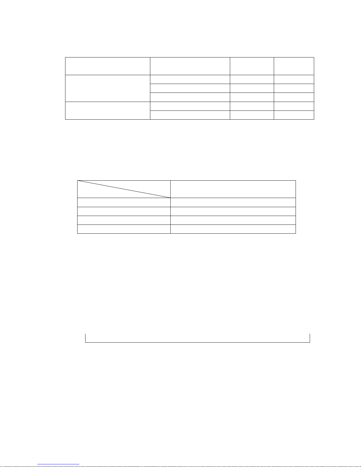
compressor, indoor fan run 5 minutes in low speed. And repeat on and off cycle.
8.7.3 Low room temperature protection:
When room temperature decreases to below 10 , the compressor and the outdoor fan ℃
will stop(indoor fan is Breeze). Dehumidifying operation will be resumed when room
temperature restores to over 13 .℃
Page 46

240
8.7.4 Under dehumidifying mode, the anti-freezing function of the indoor heat exchanger is
the same as that of cooling mode.
8.8 Heating mode
8.8.1 Generally, the 4-way valve is open in heating mode, but it is closed in defrosting mode.
4-way valve must delay 2 minutes compared with compressor if the compressor
changed into non-heating mode or turned off. 4-way valve doesn't delay in
dehumidifying mode.
8.8.2 Generally, the outdoor fan is turned off with the on-off action of compressor in heating
mode, except for the defrosting mode or the end of defrost.
8.8.3 Action conditions of compressor under heating mode: compressor must run for 7
minutes after starting and then judge temperature. Meanwhile other protections are still
valid.
Condition Compressor Outdoor fan
T A> Ts+3 Off Off Room temp. up
TA<Ts+3 On On
T A< Ts+2 On On Room temp. down
TA>Ts+2 Off Off
8.8.4 Indoor Fan actions under heating mode
Indoor Fan can be set at HIGH/MID/LOW/AUTO by using a remote controller, but
Anti-cold wind function prevails.
Anti-cold wind control function under heating mode
Condition
TE
Indoor fan speed
TE<TE1 Off
TE1<TE<TE2 Breeze
Indoor exchanger temp. up
TE>TE2 Setting fan speed
TE> TE3 Setting fan speed
TE3<TE<TE4 Breeze
Indoor exchanger temp. down
TE<TE4 Off
8.8.5 Auto wind under heating mode
Condition
T=Indoor T emp.-Setting Temp.
Indoor fan speed
T<2℃ High Room temp. up
T>2℃ Med.
T> 0℃ Med. Room temp. down
T<0℃ High
8.8.6 Indoor evaporator high-temperature protection under heating mode
Condition Compressor Outdoor fan
TE<TE8 On On
TE8<TE<TE7 On Off
Indoor exchanger temp. up
TE>TE7 Off Off
TE>TE9 Off Off Indoor exchanger temp. down
TE<TE9 On On
Page 47

241
8.9 Defrosting operation (Available for heating only).
8.9.1 Defrosting condition:
When T3<0 and compressor runs 40 minutes.℃
T3: Temp. of condenser.
8.9.2 Ending condition of defrost
If one of following conditions is satisfied, end the defrost and turn into heating:
A.The defrost time has reached to 10 minutes.
B.T3>20. ℃
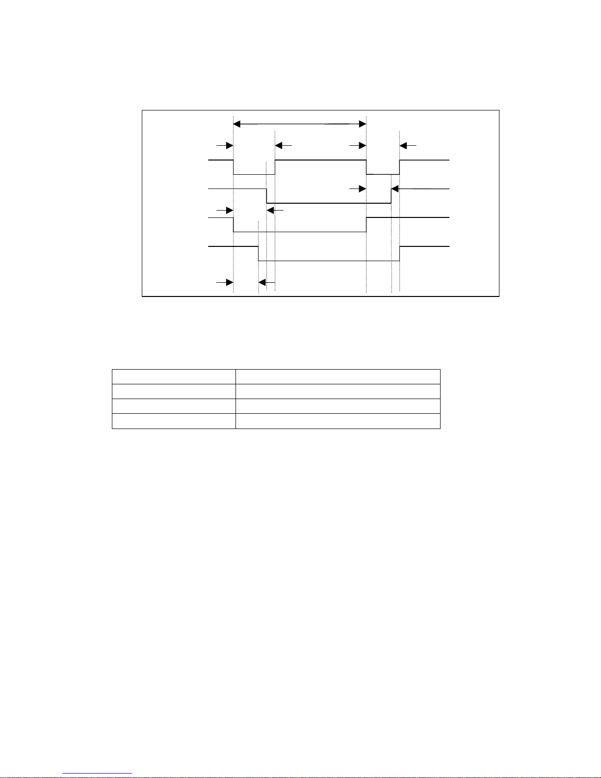
8.9.3 Time sequence of the whole defrosting procedure is as follows
8.10 Automatic operation mode
8.10.1 The air conditioner automatically selects one of the following operation modes: cooling,
heating or ventilation according to the difference between room temp. (TA) and set
temp. (TS).
TA—TS Operation mode
TA—TS>2℃ Cooling
-1 ≤TA℃ —TS≤+2℃ Fan-only
TA—TS<-1℃ Heating (Fan-only for cooling only type)
8.10.2 The indoor fan blows automatically in corresponding selected mode.
8.10.3 The motion of indoor fan’s blade should accord with the selected operation mode.
8.10.4 One mode should be carried out for at least 15 minutes once selected. If the
compressor cannot start for 15 minutes, reselect the operation mode according to the
room temp. and set temp., or reselect when the set temp. varies.
8.11 Forced cooling function
8.11.1 Select forced cooling function with the forced cooling button or the switch.
8.11.2 The compressor is unconditionally turned on, after 30 minutes cooling operation whose
fan mode is set as low, the A/C operates under the DRY mode with a set temp. of 24 .℃
8.11.3 All protections of remote control cooling are available under forced cooling operation.
8.12 Forced Auto function
Select forced auto function with the forced auto button or the switch.
In forced auto status the A/C operates under remote control mode with a set temp. of
24 .℃
Compressor
4-way Valve
Outdoor Fan
OFF
OFF
ON
ON
ON
Page 48

242
8.13 Timer Function Requirement
The maximum length of timer is 24 hours and the minimum resolving power is 15
minutes.
8.14 Economic Running
8.14.1 The economic running function is available under cooling, heating or auto mode.
8.14.2 Cooling:
The set temperature rise 1 per hour. Two hours later, the set temperature will ℃
maintain as a constant and the air circulation is kept at low speed.
8.14.3 Heating:
The set temperature decrease 1℃ per hour. Two hours later, the set temperature will
maintain as a constant and the air circulation is kept at low speed (Cold air proof
function takes precedence over all).
8.14.4 Auto:
The economic running function operates in accordance with the selected running mode
by the auto mode.
8.15 Outdoor fan motor
Fan Speed is only one SPEED.
Page 49

243
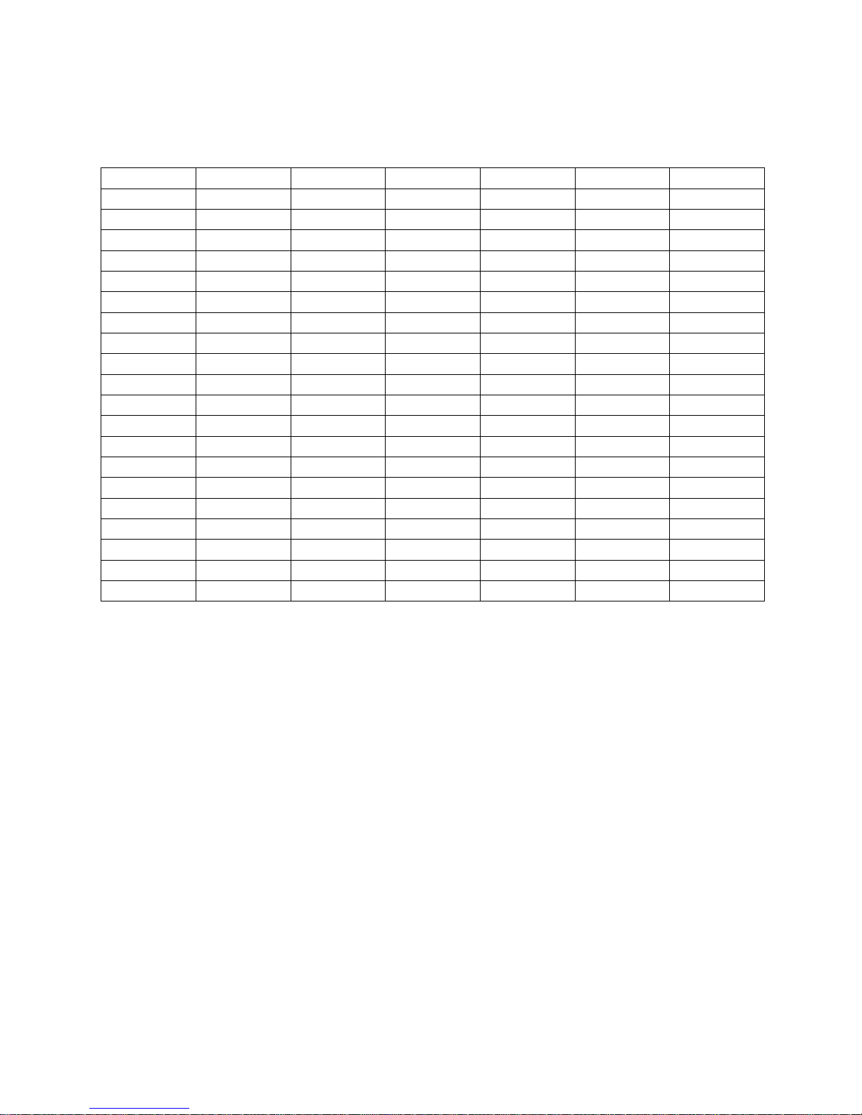
8.16 Models and Parameters(Indoor unit)
Model MS3G-30HRN2
HSPEEDH 1100
HSPEEDM 1050
HSPEEDL 1000
HSPEEDS 800
CSPEEDH 1100
CSPEEDM 1020
CSPEEDL 950
CSPEEDS 800
TE1 28℃
TE2 32℃
TE3 30℃
TE4 26℃
TE5 2℃
TE6 7℃
TE7 60℃
TE8 53℃
TE9 50℃
Page 50

Multi SERIES
1. Features 215
2. Specification 216
3. Dimensions 217
4. Refrigeration cycle diagram 218
5. Operation limits 219
6. Wiring diagram 220
7. Troubleshooting 221
8. Electronic function 222
214
Page 51

1.Features
1.1 Compact design
1.2 High efficiency and quiet operation
215
Page 52

2.Specification
Model MS2G-18HRN2 MS2G-21HRN2
Power supply Ph-V-Hz 220-240V~,1PH, 50Hz 220-240V~,1PH, 50Hz
Capacity Btu/h 9000*2 9000+12000
Input W 1000*2 1000+1400
Rated current A 4.5*2 5+6
Cooling
EER Btu/w.h 2.4 2.4
Capacity Btu/h 10000*2 10000+13000
Input W 1000*2 1000+1400
Rated current A 4.5*2 5+6
Heating
COP W/W 2.5 2.5
Moisture Removal L/h
Max. input consumption W 1430X2 1500+1900
Max. current A 6.5*2 7.0+8.0
Starting current A 19.8 33
Model PG180X1C-4DZ3 PG225X2C-4FT
Type Rotar
y
Rotar
y
Brand GD TOSHIBA GD TOSHIBA
Capacity Btu/h 10800X2 10800+13600
Input W 1000X2 1000+1290
Rated current(RLA) A 4.4X2 4.4+5.74
Locked rotor Amp(LRA) A 19.8 33
Thermal protector INNER INNER
Capacitor uF 30 35
Compressor
Refri
g
erant oil ml 400 480
Model RPG13H RPG13H
Brand WeiLin
g
WeiLin
g
Input W 36 36
Capacitor uF 1.2 1.2
Indoor fan motor
Speed(hi/mi/lo) r/min 1330 1330
Indoor air flow (Hi/Mi/Lo) m3/h 470/440/410 470/440/410
Indoor noise level (Hi/Mi/Lo) dB(A
)
38/34/31 38/34/31
Dimension (W*H*D) mm 750×250×188 750×250×188
Packing (W*H*D) mm 830X336X280 830X336X280
Indoor unit
Net/Gross wei
g
ht K
g
8.5/10 8.5/10
Model
YDK94-6A
YDK170-4C
Input W 154 290
Capacitor uF 4 5
Outdoor fan motor
S
p
eed r/min 900/670 1110/810
Outdoor air flow m3/h 1900 2070
Outdoor noise level dB(A
)
58 58
Dimension(W*H*D) mm 895X655X345 895X655X345
Packing (W*H*D) mm 1050X720X470 1050X720X470
Outdoor unit
Net/Gross weight K
g
58/63 60/65
Refrigerant type
g
R407C/800X2 R407C/750+1000
Design pressure MPa 1.2/2.8 1.2/2.8
Liquid side/ Gas side mm(inch
)
6.35(1/4")-9.53(3/8") 6.35(1/4")-9.53(3/8")/12.7(1/2")
Max. refrigerant pipe m 15 15
Refrigerant piping
Max. difference in level m 5 5
Thermostat type Electronic control Electronic control
Operation temp
℃
17-30 17-30
Ambient temp
℃
-7-45 -7-45
Application area m2
(
14-21)X2 14-21,18-26
Qty’per 20’ /40’ /40'HQ set 54/116/132 54/116/132
216
Page 53

3.Dimensions
3.1 Indoor unit
3.2 Outdoor unit
217
Page 54

4.Refrigeration cycle diagram
218
Page 55

5.Operation limits
5.1Cooling operation
Outdoor unit air temp.℃ DB
45
40
35
30
25
20
0 25 50
Indoor air temp.
℃ DB
Note : The chart is the result from the continuous operation under constant air temperature
conditions. However, excludes the initial pull-down stage.
5.2Heating operation
Indoor air temp. ℃ DB
30
25
20
15
10
5
COOLING
-5 5 15 25
Outdoor unit air temp.
℃ DB
Note : The chart is the result from the continuous operation under constant air
temperature conditions. However, excludes the initial pull-down stage.
219
Page 56

6.Wiring diagram
Indoor unit
Outdoor unit
T
5
X
T
1
R
T
3A
R
T3B
X
P
7-9
X
S
7-9
FAN
COM
P
CAP
1
S.V
X
T
3--
X
T
4
CAP
1
COM
P︵B
︶
FAN
X
T
1
X
T
2
FROM INDOOR
UNIT(A)
Y&G
R
T
3
B
R
T
3
A
X
S
8
X
S
9
X
P
8
X
P
9
(WHITE)
(BLACK)
R
T
4
X
S
7
X
P
7
(RED)
WIRING
DIAGRAM
COM
P
︵A︶
S.V
︵B︶
AC POWER
X
T3
COMPRE
S
S
OR
FAN MOTOR
OUTDOOR FAN
CAPACITOR
4-WAY VALVE
OUTDOOR COMPRE
S
S
OR
CAPACITOR
MIDDLE TERMINAL
6-WAY TERMINAL
A&B SYSTEM PIPE
TEMPERATURE SENSOR
CONNECTORS
TRANSFORMER
CONNECTORS
X
T2
4-WAY TERMINAL
RT4
A&B SYSTEM ROOM
TEMPERATURE SENSOR
PARTCODE
S.V︵A
︶
FROM INDOOR
UNIT(B)
COMP
VALVE
FAN
N
220V 50Hz
6
OUTDOOR UNIT
P1
P2
P3
P4
P5
P6
P7
P8 P9 P10 P11 P12 P13 P14
CN2 CN3
B_COMP
A_COMP
CN7
CN8
RED
BLACK
RED
RED
RED
BLUE
BLACK
RED
CAP2
CAP3
CAP2 CAP3
X
T4
T5
12
SW1
A_COMP B_COMP
RELAY
BLACK
YELLOW
C
S
R
RED
BLACK
BLUE
C
S
R
RED
BLACK
BLUE
Y&G Y&G
Y&G
 ̄
BLACK
BLACK
BLACK
BLACK
BLACK
BLUE
WHITE
RED
BLACK
BLUE
WHITE
COMP
VALVE
FAN
N
Y&G Y&G
1 2
ON
1
LEAVEING
FACTORY
EXPLANATION
1
ON
2
RAPIDLY
CHECK
2
ON
3
CHECK
ITSELF
F
UNC
TION O
F
SWITCH SW1
BLUEBLUE
RLUERLUE
P11
P10
P9
CONNECT TO FAN(HIGH SPEED)
CONNECT TO 4 WAY VALVE
P14
P13
P12
CONNECT TO 4 WAY VALVE
CONNECT TO FAN(HIGH SPEED)
220
Page 57

7.Troubleshooting
7.1 Indoor unit
Failure phenomenon Operation lamp Timer lamp
Indoor fan speed has been out of control for over 1 minute
☆
X
Indoor room temp. sensor or evaporator temp. sensor is open circuit
or short circuit
☆
on
EEPROM error on
☆
Over current protection of the compressor occurs 4 times in 1h X
☆
r Extinguish
☆ Flash at 5Hz
7.2 Outdoor unit
Failure phenomenon LED1 LED2 LED3
Stand by
☆ ☆ ☆
High temp. protect of condenser
☆ ☆
Temp. sensor in condenser 1 is open circuit or short circuit
☆
Temp. sensor in condenser 2 is open circuit or short circuit
☆
☆ Flash at 2Hz
221
Page 58

8 Electronic function
8.1 Electric Control working environment
8.1.1 input voltage: 175~253V
8.1.2 Input power frequency:50Hz
8.1.3 Ambient temperature: -7°C~+43°C
8.1.4 Indoor fan normal working amp is less than 1A,
8.1.5 Outdoor fan. Normal working amp is less than 1.5A
8.1.6 Four-way valve normal working amp is less than 1A.
8.1.7 Swing motor: DC12V.
8.2 Proper symbols and their meanings:
TA: Indoor ambient temperature
TE: Indoor evaporator temperature
TS: Setting temperature through the remote controller
TE1: Anti-cold wind, from Fan Off to Breeze temperature
TE2: Anti-cold wind, from Breeze to Setting Fan Speed temperature
TE3: Anti-cold wind, from Setting Fan Speed to Breeze temperature
TE4: Anti-cold wind, from Breeze to Fan Off temperature
TE5: Evaporator low temperature protection entering temperature
TE6: Evaporator low temperature protection restoring temperature
TE7: Evaporator high temperature protection, compressor off temperature
TE8: Evaporator high temperature protection, fan off temperature
TE9: Evaporator high temperature protection, restoring temperature
T3: Outdoor unit pipe sensor
T4: Outdoor temperature sensor
8.3 Systematic functions.
Remote receiving.
Testing and forced run.
Position set for indoor unit wind vane.
LED displaying and alarm.
On or off Timer.
Protection for the compressor.
High temperature protection of indoor heat exchanger under heating mode.
Auto defrosting and heating recovery under heating mode.
Anti cold air under heating mode.
Anti frozen under cooling mode.
222
Page 59

8.4 Protection
8.4.1 The compressor functions protection with a delay of three minutes.
8.4.2 High temp. protection of condenser.
8.4.3 Sensor protection at open circuit and breaking disconnection
8.4.4 Temperature Fuse break protection
8.4.5 Fan Speed is out of control. When Indoor Fan Speed is too high(higher than High
Fan+300RPM)or too low(lower than 400RPM), the entire unit stops and LED displays
failure information and can’t returns to normal operation automatically.
8.5 Fan-only mode
Fan speed is high/mid/low/ Auto
8.6 Cooling mode
The 4-way valve is closed under cooling mode.
The action of the compressor and the outdoor fan:
Condition Compressor Outdoor fan
TA> Ts+1 On On Temp. up
TA<Ts+1 Off Off
TA> Ts On On Temp. down
TA<Ts Off Off
Auto fan under cooling mode:
Condition
T=Indoor Temp.-Setting Temp.
Indoor fan speed
T<3℃ Low
3℃<T<5℃ Med.
Temp. up
T>5℃ High
T> 3℃ High
1℃<T<3℃ Med.
Temp. down
T<1℃ Low
Anti-freezing control to indoor evaporator under cooling mode
Condition
Temp. Time
Compressor Outdoor fan
T> TE6 On On Temp. up
T< TE6 >5 Minutes Off Off
T> TE5 On On Temp. down
T< TE5 >5 Minutes Off Off
Condenser high-temperature protection under heating mode
T3 >65℃, turn off compressor.
8.7 Dehumidifying mode
8.7.1 The 4-way valve is off in dehumidifying mode
8.7.2 Compressor and Indoor Fan actions in dehumidifying mode
Compressor run 5 minutes , and indoor fan run 5 minutes in low speed, then turn off the
compressor, indoor fan run 5 minutes in low speed. And repeat on and off cycle.
8.7.3 Low room temperature protection:
When room temperature decreases to below 10℃, the compressor and the outdoor fan
223
Page 60

will stop(indoor fan is Breeze). Dehumidifying operation will be resumed when room
temperature restores to over 13℃.
8.7.4 Under dehumidifying mode, the anti-freezing function of the indoor heat exchanger is
the same as that of cooling mode.
8.8 Heating mode
8.8.1 Generally, the 4-way valve is open in heating mode, but it is closed in defrosting mode.
4-way valve must delay 2 minutes compared with compressor if the compressor
changed into non-heating mode or turned off. 4-way valve doesn't delay in
dehumidifying mode.
8.8.2 Generally, the outdoor fan is turned off with the on-off action of compressor in heating
mode, except for the defrosting mode or the end of defrost.
8.8.3 Action conditions of compressor under heating mode: compressor must run for 7
minutes after starting and then judge temperature. Meanwhile other protections are still
valid.
Condition Compressor Outdoor fan
TA> Ts+3 Off Off Room temp. up
TA<Ts+3 On On
TA< Ts+2 On On Room temp. down
TA>Ts+2 Off Off
8.8.4 Indoor Fan actions under heating mode
Indoor Fan can be set at HIGH/MID/LOW/AUTO by using a remote controller, but
Anti-cold wind function prevails.
Anti-cold wind control function under heating mode
Condition
TE
Indoor fan speed
TE<TE1 Off
TE1<TE<TE2 Breeze
Indoor exchanger temp. up
TE>TE2 Setting fan speed
TE> TE3 Setting fan speed
TE3<TE<TE4 Breeze
Indoor exchanger temp. down
TE<TE4 Off
8.8.5 Auto wind under heating mode
Condition
T=Indoor Temp.-Setting Temp.
Indoor fan speed
T<2℃ High Room temp. up
T>2℃ Med.
T> 0℃ Med. Room temp. down
T<0℃ High
224
Page 61

8.8.6 Indoor evaporator high-temperature protection under heating mode
Condition Compressor Outdoor fan
TE<TE8 On On
TE8<TE<TE7 On Off
Indoor exchanger temp. up
TE>TE7 Off Off
TE>TE9 Off Off Indoor exchanger temp. down
TE<TE9 On On
8.9 Defrosting operation (Available for heating only).
8.9.1 Defrosting condition:
When T3<0℃ and compressor runs 40 minutes.
T3: Temp. of condenser.
8.9.2 Ending condition of defrost
If one of following conditions is satisfied, end the defrost and turn into heating:
A.The defrost time has reached to 10 minutes.
B.T3>20. ℃
8.9.3 Time sequence of the whole defrosting procedure is as follows
Compressor
4-way Valve
Outdoor Fan
OFF
OFF
ON
ON
ON
8.10 Automatic operation mode
8.10.1 The air conditioner automatically selects one of the following operation modes: cooling,
heating or ventilation according to the difference between room temp. (TA) and set
temp. (TS).
TA—TS Operation mode
TA—TS>2℃ Cooling
-1 ≤TA℃ —TS≤+2℃ Fan-only
TA— TS <- 1℃ Heating (Fan-only for cooling only type)
8.10.2 The indoor fan blows automatically in corresponding selected mode.
8.10.3 The motion of indoor fan’s blade should accord with the selected operation mode.
8.10.4 One mode should be carried out for at least 15 minutes once selected. If the
compressor cannot start for 15 minutes, reselect the operation mode according to the
room temp. and set temp., or reselect when the set temp. varies.
225
Page 62

8.11 Forced cooling function
8.11.1 Select forced cooling function with the forced cooling button or the switch.
8.11.2 The compressor is unconditionally turned on, after 30 minutes cooling operation whose
fan mode is set as low, the A/C operates under the DRY mode with a set temp. of 24℃.
8.11.3 All protections of remote control cooling are available under forced cooling operation.
8.12 Forced Auto function
Select forced auto function with the forced auto button or the switch.
In forced auto status the A/C operates under remote control mode with a set temp. of
24℃.
8.13 Timer Function Requirement
The maximum length of timer is 24 hours and the minimum resolving power is 15
minutes.
8.14 Economic Running
8.14.1 The economic running function is available under cooling, heating or auto mode.
8.14.2 Cooling:
The set temperature rise 1℃ per hour. Two hours later, the set temperature will
maintain as a constant and the air circulation is kept at low speed.
8.14.3 Heating:
The set temperature decrease 1℃ per hour. Two hours later, the set temperature will
maintain as a constant and the air circulation is kept at low speed (Cold air proof
function takes precedence over all).
8.14.4 Auto:
The economic running function operates in accordance with the selected running mode
by the auto mode.
8.15 Outdoor fan motor
T4: Outdoor temp.
T4 Outdoor fan motor
T4>27℃ High speed Cooling mode
T4<25℃ Low speed
T4>13℃ Low speed Heating mode
T4<11℃ High speed
226
Page 63

227
8.16 Models and Parameters(Indoor unit)
Model MS2G-18CR MS2G-18HR
HSPEEDH 1100
HSPEEDM 1050
HSPEEDL 1000
HSPEEDS 800
CSPEEDH 1100 1100
CSPEEDM 1020 1020
CSPEEDL 950 950
CSPEEDS 800 800
TE1 28℃
TE2 32℃
TE3 30℃
TE4 26℃
TE5 4℃ 4℃
TE6 7℃ 7℃
TE7 60℃
TE8 53℃
TE9 50℃
Page 64

197
MULTI INVERTER ECO
1. Product features 198
2. Specification 199
3. Dimensions 203
4. Refrigeration cycle diagram 204
5. Operation limits 205
6. Capacity table 206
7. Wiring diagram 208
8. Electric control functions 210
Page 65

198
1. Product Features
Both indoor units can be operated either simultaneously or separately through the utilization of the advanced
converter technique and microcomputer control.
The flowing volume of refrigerant is adjustable through the electronic expansion valve.
High Cooling and Heating capacity is facilitated through the famous-brand frequency converter compressor.
Indoor noise is minimized through the optimization of the air flow system design, a four-folded evaporator and a
big diameter Cross Flow Fan.
The system is operable under low-voltage.
Effective and prompt defrosting correlates into no cold feelings.
High heating effects under extremely low temperatures.
The systems purging function improves the quality of the air in the room.
Wireless remote controlled function:
---A Manual Switch can operate the air conditioner when the remote controller is misplaced and the batteries are
exhausted.
---Horizontal and vertical louvers can swing automatically and the customized setting flows the air as desired.
---Grounding's have been connected and are safe to use.
---Compressor protection function enabled.
Indoor unit:
1) 4-Bend heat exchanger.
2) Trapeziform innergroove copper.
3) Hydrophilic Aluminum Fin.
4) Two-direction air vane technology.
5) Sleep mode.
6) Anti-rust cabinet.
7) Easy-cleaned panel.
8) Self-diagnosis auto-protection function.
Page 66

199
2. Specification
Model M2OA-18HRIN2
Indoor unit 7000Btu/h 9000Btu/h 12000Btu/h
Power supply Ph-V-Hz 1Ph, 220-240V~, 50Hz
Capacity Btu/h single: 7000-12000; Twin:16000-24000
Input W single: 1000W-1350W; Twin:2570W-2900W
Rated current A single: 4.8A-6.7A; Twin:11.7A-13.8A
Cooling
EER Btu/w.h single: 7.0-8.9; Twin:6.2-8.3
Capacity Btu/h single: 10000-14000; Twin:24000-27000
Input W single: 1300W-1650W; Twin:2100W-2800W
Rated current A single: 6.3A-8.0A; Twin:11.0A-13.5A
Heating
COP Btu/w.h single: 7.7-8.5; Twin:11.4-9.6
Moisture Removal L/h 0.7 0.9 1.2
Max. input consumption W single: 1800W; Twin:3200W
Max. current A single: 13A; Twin:20A
Starting current A 10
Model
BG240X2CS-20KU
Type Rotary inverter
Brand GD Toshiba
Capacity Btu/h 18000
Input W 1690
Rated current(RLA) A 11.6
Locked rotor Amp(LRA) A 60
Thermal protector Internal
Capacitor uF 85UF/250V
Compress
or
Refrigerant oil ml RB68AF/α68TF/T-68 750 ml
Model
RPG13H RPG13H RPG13C
Brand
Welling Welling Matsushita
Input W
36
36
50
Capacitor uF
1.2uF/≥450VAC 1.2uF/≥450VAC 1.5uF/≥450VAC
Indoor
fan motor
Speed(hi/mi/lo) r/min 1050/950/750 1100/1000/800 1060/900/800
Number of rows 2 2
2
Tube pitch(a)x row pitch(b) mm 21×13.37 21×13.37
21×13.37
Fin spacing mm 1.5 1.5
1.3
Fin type (code)
Hydrophilic
aluminium
Hydrophilic
aluminium
Hydrophilic
aluminium
Tube outside dia.and type mm
φ7, innergroove
tube
φ7, innergroove
tube
φ7, innergroove
tube
Coil length x height x width mm 578×252×27.34 578×252×27.34
635×315×27.34
Indoor
coil
Number of circuits 2 2
2
Page 67

200
Indoor air flow (Hi/Mi/Lo) m3/h 500/410/320 520/430/330
560/460/380
Indoor noise level (Hi/Mi/Lo) dB(A) 35/32/26 36/32/26
36/32/26
Dimension (W*H*D) mm
750*250*188 750*250*188 815*280*195
Packing (W*H*D) mm
830*336*280 830*336*280 915*360*275
Indoor
unit
Net/Gross weight kg
8.5/11 8.5/11 11/14
Model YDK53-6M
Brand Welling
Input W 148
Capacitor uF 3.0
Outdoor
fan motor
Speed r/min 775
Number of rows 1.5
Tube pitch(a)x row pitch(b) mm 25.4×22
Fin spacing mm 1.7
Fin type (code) Hydrophilic aluminium
Tube outside dia.and type mm φ9.53 innergroove trube
Coil length x height x width mm 776×660×22
Outdoor
coil
Number of circuits 2
Outdoor air flow m3/h 2500
Outdoor noise level dB(A) 60
Dimension(W*H*D) mm 845X695X335
Packing (W*H*D) mm 975X772X405
Outdoor
unit
Net/Gross weight kg 71/74
Refrigerant type R407C g 2200
Design pressure(Hi/Lo) MPa 2.8/1.2
Liquid side/ Gas side mm Ф6.35/Ф9.53 Ф6.35/Ф9.53
Ф6.35/Ф12.7
Max. refrigerant pipe length m 10 10 10
Refrigera
nt piping
Max. difference in level m 5 5 5
Connection wiring No
Plug type No
Controller Remote
Operation temp ℃ 17~30
Ambient temp ℃ 18~43(cooling); -15~24(heating)
Application area m2
14-18 18-24 20-30
Notes: 1. Nominal cooling capacities are based on the following conditions:
Indoor temp: 27°CDB, 19°CWB; Outdoor temp: 35°CDB; Equivalent ref. Piping: 8m(horizontal)
2. Nominal heating capacities are based on the following conditions:
Indoor temp: 20°CDB; Outdoor temp: 7°CDB, 6°CWB; Equivalent ref. Piping: 8m(horizontal)
3. Actual noise level may differ, depending on the room structure, etc, since these noise values are from an
anechoic room.
Page 68

201
Model M3OA-27HRIN2
Indoor unit 7000Btu/h 9000Btu/h 12000Btu/h
Power supply Ph-V -Hz 1Ph, 220-240V~, 50Hz
Capacity Btu/h single: 7000-12000; Twin:16000-24000; Three:24000
Input W single: 1000W-1350W; Twin:2570W-2900W; Three:2900W
Rated current A single: 4.8A-6.7A; Twin:11.1A-13.8A; Three: 13.8A
Cooling
EER Btu/w.h single: 7.0-8.9; Twin: 6.2-8.3; Three: 8.3
Capacity Btu/h single: 10000-14000; Twin: 24000-27000; Three: 27000
Input W single: 1300W-1650W; Twin: 2100W-2800W; Three: 2800W
Rated current A single: 6.3A-8.0A; Twin: 11.0A-13.5A; Three: 13.5A
Heating
COP Btu/w.h single: 7.7-8.5; Twin: 11.4-9.6; Three: 9.6
Moisture Removal L/h 0.7 0.9 1.2
Max. input consumption W 3200
Max. current A 20
Starting current A 10
Model
BG240X2CS-20KU
Type Rotary inverter
Brand GD Toshiba
Capacity Btu/h 18000
Input W 1690
Rated current(RLA) A 11.6
Locked rotor Amp(LRA) A 60
Thermal protector Internal
Capacitor uF 85UF/250V
Compress
or
Refrigerant oil ml RB68AF/α68TF/T-68 750 ml
Model
RPG13H RPG13H RPG13C
Brand
Welling Welling Matsushita
Input W
36
36
50
Capacitor uF
1.2uF/≥450VAC 1.2uF/≥450VAC 1.5uF/≥450VAC
Indoor
fan motor
Speed(hi/mi/lo) r/min 1050/950/750 1100/1000/800 1060/900/800
Number of rows 2 2
2
Tube pitch(a)x row pitch(b) mm 21×13.37 21×13.37
21×13.37
Fin spacing mm 1.5 1.5
1.3
Fin type (code)
Hydrophilic
aluminium
Hydrophilic
aluminium
Hydr0philiC
aluminium
Indoor
coil
Tube outside dia.and type mm
φ7, innergroove tube φ7, innergroove tube
φ7, innergroove tube
Page 69

202
Coil length x height x width mm 578×252×27.34 578×252×27.34
635×315×27.34
Number of circuits 2 2
2
Indoor air flow (Hi/Mi/Lo) m3/h 500/410/320 520/430/330
560/460/380
Indoor noise level (Hi/Mi/Lo) dB(A) 35/32/26 36/32/26
36/32/26
Dimension (W*H*D) mm 750*250*188 750*250*188 815*280*195
Packing (W*H*D) mm
830*336*280 830*336*280 915*360*275
Indoor
unit
Net/Gross weight Kg
8.5/11 8.5/11 11/14
Model YDK53-6M
Brand Welling
Input W 148
Capacitor uF 3.0
Outdoor
fan motor
Speed r/min 775
Number of rows 1.5
Tube pitch(a)x row pitch(b) mm 25.4×22
Fin spacing mm 1.7
Fin type (code) Hydrophilic aluminium
Tube outside dia.and type mm φ9.53 innergroove trube
Coil length x height x width mm 776×660×22
Outdoor
coil
Number of circuits 2
Outdoor air flow m3/h 2500
Outdoor noise level dB(A) 60
Dimension(W*H*D) mm 845X695X335
Packing (W*H*D) mm 975X772X405
Outdoor
unit
Net/Gross weight Kg 72/76
Refrigerant type R407C g 2400
Design pressure(Hi/Lo) MPa 2.8/1.2
Liquid side/ Gas side mm Ф6.35/Ф9.53 Ф6.35/Ф9.53
Ф6.35/Ф12.7
Max. refrigerant pipe length m 10 10 10
Refrigera
nt piping
Max. difference in level m 5 5 5
Connection wiring No
Plug type No
Controller Remote
Operation temp ℃ 17~30
Ambient temp ℃ 18~43(cooling); -15~24(heating)
Application area m2
14-18 18-24 20-30
Notes: 1. Nominal cooling capacities are based on the following conditions:
Indoor temp: 27°CDB, 19°CWB; Outdoor temp: 35°CDB; Equivalent ref. Piping: 8m(horizontal)
2. Nominal heating capacities are based on the following conditions:
Indoor temp: 20°CDB; Outdoor temp: 7°CDB, 6°CWB; Equivalent ref. Piping: 8m(horizontal)
3. Actual noise level may differ, depending on the room structure, etc, since these noise values are from an
anechoic room.
Page 70

203
3 Dimensions
1. Indoor unit 7/9K
2. Indoor Unit 12K
3. Outdoor unit
Page 71

204
4 Refrigeration Cycle Diagram
Refrigeration circuit drawing of inverter trinary type
2
heat
exchanger
filter
heat
exchanger
filter
filter
indoor unit
heat
exchanger
filter
high-pressure
switch 1
4-way
valve
down part
condenser
3
capillary
capillary
filter
up part
oil separator
low-pressure
switch 2
low-pressure oil tank
capillary
discharge
sensor
outdoor unit
inverter compressor
Refrigeration circuit drawing of inverter binary type
2
heat
exchanger
filter
heat
exchanger
filter
high-pressure
switch 1
4-way
valve
condenser
down part
3
capillary
capillary
filter
up part
oil separator
low-pressure
switch 2
low-pressure oil tank
capillary
discharge
sensor
outdoor unit
inverter compressor
Page 72

205
5 Operation Limits
5.1 Cooling operation
Outdoor unit air temp.℃
60
50
40
30
20
10
10 17 25 30 35 40
Indoor air temp.
℃
Note :the chart is the result from the continuous operation under constant air temperature
conditions. however, excludes the initial pull-down stage.
5.2 Heating operation
Indoor air temp. ℃
30
20
10
5
-5
-15
-15 -5 5 15 25 30
Outdoor unit air temp.
℃
Note :the chart is the result from the continuous operation under constant air
temperature conditions. however, excludes the initial pull-down stage.
Page 73

206
6 Capacity Table
6.1 Capacity table of Inverter Binary Eco type
Indoor units can be combined by
7000Btu/h+9000 Btu/h;
7000Btu/h+12000 Btu/h
9000Btu/h+9000 Btu/h
9000Btu/h+12000 Btu/h
12000Btu/h+12000 Btu/h
Cooling
Indoor unit a (W) Indoor unit b (W)
7000Btu/h 2800
9000Btu/h 3000
12000Btu/h 3400
7000Btu/h+7000 Btu/h 2300 2300
7000Btu/h+9000 Btu/h 2500 2500
7000Btu/h+12000 Btu/h 2200 2800
9000Btu/h+9000 Btu/h 2500 2500
9000Btu/h+12000 Btu/h 2400 3200
12000Btu/h+12000 Btu/h 3200 3200
Heating
Indoor unit a (W) Indoor unit b (W)
7000Btu/h 3400
9000Btu/h 3600
12000Btu/h 4000
7000Btu/h+7000 Btu/h 2800 2800
7000Btu/h+9000 Btu/h 3000 3000
7000Btu/h+12000 Btu/h 2600 3400
9000Btu/h+9000 Btu/h 3000 3000
9000Btu/h+12000 Btu/h 3000 3900
12000Btu/h+12000 Btu/h 3900 3900
6.2 Capacity table of Inverter Trinary Eco type
Indoor units can be combined by
7000Btu/h*2+9000 Btu/h;
7000Btu/h*2+12000 Btu/h
7000Btu/h*3
9000Btu/h*2+7000 Btu/h
9000Btu/h*2+12000 Btu/h
9000Btu/h*3
12000Btu/h*2+7000 Btu/h
12000Btu/h*2+9000 Btu/h
7000Btu/h+9000Btu/h+12000 Btu/h
Page 74

207
Cooling
Indoor unit a (W) Indoor unit b (W) Indoor unit c (W)
7000Btu/h 2800
9000Btu/h 3000
12000Btu/h 3400
7000Btu/h+7000 Btu/h 2300 2300
7000Btu/h+9000 Btu/h 2500 2500
7000Btu/h+12000 Btu/h 2200 2800
9000Btu/h+9000 Btu/h 2500 2500
9000Btu/h+12000 Btu/h 2400 3200
12000Btu/h+12000 Btu/h 3200 3200
7000Btu/h*2+9000 Btu/h 2200 2200 2200
7000Btu/h*2+12000 Btu/h 2000 2000 2600
7000Btu/h*3 2200 2200 2200
9000Btu/h*2+7000 Btu/h 2200 2200 2200
9000Btu/h*2+12000 Btu/h 2100 2100 2600
9000Btu/h*3 2200 2200 2200
12000Btu/h*2+7000 Btu/h 2000 2400 2400
12000Btu/h*2+9000 Btu/h 2000 2400 2400
Heating
Indoor unit a (W) Indoor unit b (W) Indoor unit c (W)
7000Btu/h 3400
9000Btu/h 3600
12000Btu/h 4000
7000Btu/h+7000 Btu/h 2800 2800
7000Btu/h+9000 Btu/h 3000 3000
7000Btu/h+12000 Btu/h 2600 3400
9000Btu/h+9000 Btu/h 3000 3000
9000Btu/h+12000 Btu/h 3000 3900
12000Btu/h+12000 Btu/h 3900 3900
7000Btu/h*2+9000 Btu/h 2600 2600 2600
7000Btu/h*2+12000 Btu/h 2300 2300 3200
7000Btu/h*3 2400 2400 2400
9000Btu/h*2+7000 Btu/h 2700 2700 2700
9000Btu/h*2+12000 Btu/h 2500 2500 3200
9000Btu/h*3 2700 2700 2700
12000Btu/h*2+7000 Btu/h 2400 3200 3200
12000Btu/h*2+9000 Btu/h 2400 3200 3200
Page 75

208
7. Wiring Diagram
7.1 Indoor unit 7/9K
7.2 Indoor unit 12K
Page 76

209
7.3 Outdoor unit M2OA-18HRIN2
Outdoor unit M3OA-27HRIN2
Page 77

210
8. Electric Control Functions
8.1 Control system
The control system adopts modular design, that is, all indoor units communicate with outdoor units, ref. to the
following figures for the control structure between indoor units and outdoor units. In the structure, the indoor control
board receives the information from users (for exam. set temp., fan speed etc.) and environment (ex, indoor coil
temp., indoor temp. etc.) ,and organize it to control the action of relevant parts, then transmits the signals to outdoor
control board through the following communication circuit. Outdoor control board can deal with the information
from indoor unit and figure out the best running mode, then transfer the instruction to indoor units to carry out it.
Indoor unit receive the user’s remote control signals.
Indoor unit Outdoor unit
T
2B
T1、T2、Ts T3、 T4、T3
Fan Speed Pressure switch
Pressure switch
4-way valve
Fan Fan motor
通讯 Co Compressor
Swing motor EXV
1、 T1 Indoor ambient temp.
2、 T2 Indoor evaporator middle part temp
3、 T2B Indoor evaporator outlet temp.
4、 Ts Indoor setting temp.
5、 T3 Outdoor heat-exchanger outlet temp.
6、 T4 Outdoor ambient temp.
8.2 Protection function
8.2.1 AC Volt Protection
a. Over-voltage protection
When AC voltage ≤ 260V for 30 seconds, Outdoor Unit resumes operation.
When AC voltage ≥ 270V for 30 seconds, Outdoor Unit stops operation and alarms.
Note: Voltage sampling precision is
±3%.
b. Lack-voltage protection
ote control
Page 78

211
Volt increase (Resume)
198
190 MAX=78Hz 190
180
172 MAX=70Hz 172
167
Stop
Volt decrease (Limited Frequency)
8.2.2 AC Amp Protection
The outdoor control board checks the compressor current and do over-current protection.
If the compressor current is over the scheduled value, the system will stop and all indoor units will display
malfunction code.
Note: 1. In order to prev ent protect ion due to too big LRA when compressor starts, the outdoor control board begin s
to check the compressor current after 10 seconds.
2. If current protection happens, the compressor will stop and restart 3 minutes later.
8.2.3 High-pressure Protection and Low-pressure Protection
The High-pressure switch and Low-pressure switch are installed at suction pipe and discharge pipe separately. And
users can select to install. Normally, the high-pressure switch is cut down when higher than
425Psi (3.3Mpa Cut
down, 2.4Mpa Resume). While the low-pressure switch is cut down when lower than 7Psi (0.05Mpa
On, 0.15Mpa Resume).
Under high-pressure protection or low-pressure protection, the compressor will stop and restart 3
minutes later.
8.2.4 Outdoor Unit communication protection
8.2.4.1 Communication protection between indoor unit and outdoor system chip
If the outdoor unit can’t receive the indoor signal for 30 seconds, then the indoor units are judged as no starting and
there is no alarm signal. If the indoor units send signal to system chip for 2 minutes and no feedback signal is
received, then judge as communication malfunction.
8.2.4.2 Communication protection between outdoor system chip and inverter chip
If can’t receive signal or receive wrong signal for over 2 minutes, Indoor/Outdoor Unit stops operation. When the
signal is right, Indoor/Outdoor Unit restarts.
8.2.5 Outdoor condenser high temperature protection
Under cooling mode, if
T3〉65℃ for 3 minutes, the compressor will stop. When T3〈52℃, the protection
is not valid.
When protection is released, the compressor restarts 3 minutes later.
Volt(V)
Page 79

212
8.2.6 T emperature Sensor short/open protection
When the outdoor condenser pipe temperature T3, outdoor ambient temperature T4, indoor evaporator outlet
temperature
T2B are checked out of range 0.05~4.95V, it think temperature sensor short/open
protection. The compressor, four-way valve and outdoor fan motor will stop and send malfunction
signal to indoor units.
When the volt is resumed to the range 0.05~4.95V, then resume signal to indoor units and control
on-off of the compressor, four-way valve and outdoor fan motor by indoor size.
8.2.7 Outdoor low temperature protection
If the outdoor temperature is lower than -15℃ for 1hour, the compressor and fan motor will stop. And
any operation is not valid.
If the outdoor temperature is higher than -12℃ for 10 minutes and the compressor stops operation
for 1h, or the outdoor temperature is higher than 5℃ for 10 minutes, then restart and enter into the
prior operation mode.
If any indoor unit sends out this protection request, the outdoor unit will stop compressor until all
indoor units have not this protection request.
8.2.8 Compressor pre-heating function
When the outdoor temperature is lower than 3℃ and the compressor stops operation for more than 3
hours, or the outdoor temperature is lower than 3℃ and the power is just put on, the compressor
enters into pre-heating condition.
8.3 Display function
8.3.1 Checking function
The indoor and outdoor operation condition can be examined by check button.
Normal display Operation mode Capacity request Number of indoor units ambient temp.
Outdoor pipe temp. Compressor current No.1 PMV opening No.2 PMV opening
No.3 PMV opening
8.3.2 Explanation of display function
1. “--”: Standing-by
2. When the compressor is in operation, the compressor operation frequency will be displayed on
the digital pipe.
3. “dF”: Defrosting
4. Under standing-by, display“--” when pre-heating and display “11.” When pre-heating after
turning on the AC.
5. Under malfunction protection:
Page 80

213
Display contents Malfunction or Protection
E 0 EEPROM Parameter Malfunction
E1 No.1 Indoor unit Evaporator outlet temp. sensor malfunction
E2 No.2 Indoor unit Evaporator outlet temp. sensor malfunction
E3 No.3 Indoor unit Evaporator outlet temp. sensor malfunction
E4 Outdoor temp. sensor malfunction
E5 Compressor volt protection
E6 Obligate
E 7 Outdoor inverter communication malfunction
P 0 Top temp. protection
P1
High-pressure protection
P2
Low-pressure protection
P3
Compressor current protection
P4 Module protection
P5 Outdoor low-temperature protection
P6 Condenser high-temperature protection
P 7 Obligate
Page 81

178
AC INVERTER SERIES II
1. Features 179
2. Specification 180
3. Dimensions 182
4. Refrigeration cycle diagram 184
5. Operation limits 185
6. Wiring diagram 186
7. Troubleshooting 189
8. Electronic function 190
Page 82

179
1.Features
1.1 Powerful at cooling/heating, 1.3 times and 1.6 times relatively higher than normal same type of
models.
1.2 Low voltage start-up function, even at 160 V it can normally start.
1.3 Anti-icing function at cooling mode.
1.4 Anti-cold air function at heating mode.
1.5 Auto-defrosting and heating recovering function at heating mode.
1.6 Outdoor whole electric current protection
1.7 Temperature protection of the outdoor compressor top.
1.8 Restart protection for the compressor.
1.9 24 hours on/off mode time setting.
1.10 Error self diagnosis function.
1.11 Protection against over-load or too-low current inputted through alternating current.
Page 83

180
2. Specification
Model MSG-09HRI MSG-12HRI
Power supply Ph-V-Hz 220-240V, 50HZ 220-240V, 50HZ
Capacity Btu/h 9000(2730-10600) 12000(3070-12300)
Input W 1080(270-1470) 1260(310-1710)
Rated current A 6(1.45-7.60) 7.2(1.60-8.80)
Cooling
EER Btu/w.h 8.3 9.52
Capacity Btu/h 12000(2730-14000) 15000(3070-17060)
Input W 1350(270-1800) 1790(300-2380)
Rated current A 7.2(1.45-9.30) 8.4(1.60-12.30)
Heating
COP W/W 2.6 2.5
Moisture Removal L/h 1 1.2
Max. input consumption W 2300 2600
Model 2PV132N7BC02 2PV132N7BC02
Type Rotary Rotary
Brand MATSUSHITA MATSUSHITA
Capacity Btu/h 8900 8900
Input W 855 855
Rated current(RLA) A 5.1 5.1
Locked rotor Amp(LRA) A 16 16
Thermal protector CS-7LN120 CS-7LN120
Compressor
Refrigerant oil ml 350 350
Model RPG13F RPG20A
Input W 36.5 35
Capacitor uF 1.2UF/450VAC 1UF/450VAC
Indoor fan motor
Speed(hi/mi/lo) r/min 1100/1000/900 1100/1000/900
Indoor air flow (Hi/Mi/Lo) m3/h 500 540
Indoor noise level (Hi/Mi/Lo) dB(A) 36/32/26 38/34/28
Dimension (W*H*D) mm 750X250X188 875X270X176
Packing (W*H*D) mm 870X336X280 1000X355X265
Indoor unit
Net/Gross weight Kg 8.5/11 11/14
Model YDK20-6g YDK25-6-3
Input W 70 75
Capacitor uF 2.5 2.5
Outdoor fan motor
Speed r/min 800 900
Outdoor noise level dB(A) 50 53
Dimension(W*H*D) mm 780X540X240 780X540X240
Packing (W*H*D) mm 910X575X335 910X575X335
Outdoor unit
Net/Gross weight Kg 36/39 40/43
Refrigerant type g 870 1120
Design pressure MPa 2.6 2.6
Liquid side/ Vapor side mm(inch) Ф6.35/Ф9.53 Ф6.35/Ф12.7
Max. refrigerant pipe length m 10 10
Refrigerant piping
Max. difference in level m 5 5
A
pplication area m2 18-24 20-30
★1 The noise date is base on hemi-anechoic chamber, during actual operation, these values are normally somewhat different as a result of ambient
condition.
Page 84

181
Model Item MSG-07HRIN2 MSG-09HRIN2 MSG-12HRIN2
Power source 220-240V~ 50Hz 220-240V~ 50Hz 220-240V~ 50Hz
Capacity BTU/H 7000(2700~9000) 9000(2730~10600) 12000(3070~12300)
Input W 820(250~1200) 1080(270~1470) 1400(310~1710)
Running current A 4.8(1.35~6.2) 6.0(1.45~7.6) 7.5(1.6~8.8)
Cooling
EER BTU/W.H 8.3 8.3 8.6
Capacity BTU/H 9000(2700~11000) 12000(2730~14000) 14000(3070~17000)
Input W 1010(250~1300) 1400(270~1800) 1790(300~2380)
Heating
Running current A 5.6(1.35~6.7) 7.2(1.49~9.3) 10.5(1.6~12.3)
Max. input consumption W 2100 2300 2600
Model BG130X1C-20FZ BG130X1C-20FZ BG130X1C-20FZ
Type Rotary Inverter Rotary Inverter Rotary Inverter
Brand MIDEA T OS HIBA MIDEA TOSHIBA MIDEA TOS HIBA
Refrigerant oil ml 370 370 370
Compressor
Refrigerant oil type R407C R407C R407C
Refrigerant R407C g 800 800 1150
Design pressure MPa 2.6 2.6 2.6
Input W RPG13H 36 RPG13H 36 RPG13C 50
Capacitor uF 1.2uF/≥450VAC 1.2uF/≥450VAC 1.5uF/≥450VAC
Speed level 3 3 3
Hi speed( rpm) 1100 1100 1060
Mid speed( rpm) 1000 1000 900
Indoor fan
motor
Low speed( rpm) 800 800 800
High fan m3/h 500 520 560
Middle fan m3/h 430 430 460
Air flow
(indoor)
Low fan m3/h 330 330 380
Noise level
(indoor)
dB(A) 35/32/26
36/32/26 36/32/26
Input W YDK23-6G 63 YDK23-6G 63 YDK23-6G 63 Outdoor fan
motor
Capacitor uF 2.5uF/≥450VAC 2.5uF/≥450VAC 2.5uF/≥450VAC
Noise
(outdoor)
High dB(A) ≤51 ≤51 ≤53
dimension(W*H*D) 750*250*188 750*250*188 815*280*195
Packing (W*H*D) 830*336*280 830*336*280 915*360*275
Indoor unit
Net weight kg 8.5 8.5 11
dimension(W*H*D) 780*520*240 780*520*240 780*520*240
Packing (W*H*D) 910*575*335 910*575*335 910*575*335
Outdoor unit
Net weight kg 37 37 40
★1 The noise date is base on anechoic chamber, during actual operation, these values are normally somewhat different as a result of ambient
condition.
Page 85

182
3. Dimensions
3.1 Indoor Unit(MSG-09HRI, MSG-07/09HRIN2)
3.2 Indoor Unit(MSG-12HR1)
Page 86

183
3.3 Indoor Unit (MSG-12HRIN2)
3.4 Outdoor Unit
Page 87

184
4. Refrigeration Cycle Diagram
Indoor unit outdoor unit
Valve
Sensor of room temp Heat exchanger
. 4 way valve
Sensor
Heat exchanger Sensor of temp
Sensor of heat exchanger temp
. Sensor of heat exchanger temp
Compressor
Valve Capillary
Page 88

185
5. Operation Limits
5.1 Cooling operation
Outdoor unit air temp.℃
60
50
40
30
20
10
10 17 25 30 35 40
Indoor air temp.
℃
Note :the chart is the result from the continuous operation under constant air temperature
conditions. however, excludes the initial pull-down stage.
5.2 Heating operation
Indoor air temp. ℃
30
20
10
5
-5
-15
-15 -5 5 15 25 30
Outdoor unit air temp.
℃
Note :the chart is the result from the continuous operation under constant air
temperature conditions. however, excludes the initial pull-down stage.
Page 89

186
6.
Wiring Diagram
Indoor unit(MSG-09HRI MSG-07HRIN2 MSG-09HRIN2)
Indoor unit (MSG-12HRI)
CN4
CN7
CN12
CN11
TRANSFORMER
INDOOR
FAN
OUTDOOR
2(N)
L N S
1
RED
BLACK
WHITE
4
YELLOW
3
Y&G
YELLOW
BLUE
BLACK
Y&G
CN9
BROWN/RED
2
CN14
CN15
CN01
CN4
CN21
9
CN2
CN20
CZ3
2
3
2
M
3
3
5
M
LOUVER
MOTOR
SWITCH
BOARD
DISPLAY
BOARD
OVERHEAT
PROTECTER
AMBIENT
SENSER
HEAT EXCHANGE
SENSER
Page 90

187
Outdoor unit (MSG-09HRI,MSG-12HRI)
S
NL
Page 91

188
Indoor unit(MSG-12HRIN2)
Outdoor unit (MSG-07HRIN2 / MSG-09HRIN2 / MSG-12HRIN2)
NL
S
Page 92

189
7.Troubleshooting
7.1 Indoor Unit Error Display Function
LED4 operation LED2 defrosting LED1 timer LED4 auto
LED2
defrost
LED1
Timer
LED3
Auto
LED4
operation
LED STATUS
X X O ☆ Mold protection
O X X ☆ Compressor top protection against temperature
X O X ☆ Open or short circuit of outdoor temperature sensor
X O O ☆ Over load or too low voltage protection
O O O ☆
Room temperature or evaporator temperature sensor open
or short circuit of
O O ☆ ☆ Fan speed beyond control
☆ X O ☆ Zero-crossing examination error
☆ O X ☆ Temperature fuse protection
X X ☆ ☆ EEPROM data error
☆ O X ☆ Types doesn't match
☆ ☆ ☆ ☆ Indoor / outdoor units communication protection
O (on) X (off) ☆ (flash)
7.2.Outdoor Unit Error Self-diagnosis Display
Outdoor Unit Error: if L4 flashes at 1Hz.
Outdoor unit works: L4 on
Outdoor unit Stand by: if L4 flashes at 0.5Hz
Page 93

190
8 .Electronic Function
8.1 General Protection
8.1.1 Temperature Protection of Compressor Top
8.1.2 3 minutes Delayed Starting Protection of the Compressor
8.1.3 Voltage Protection
8.1.4 The frequency Up-Down speed at which the compressor starts, operates and shuts off will be
subject to the following principles (outdoor chip):
8.1.5 Frequency Converter Mold Protection (outdoor chip):
The Frequency Converter Mold itself has a protection function against current, voltage and
temperature, if there are 4 times of above mentioned protection functioning within 1 hour (when
the compressor's consecutive operation lasts more than 10 minutes, the fore-mentioned 4
counts will be cleared), the whole machine will shut off and the mold protection gives an alarm.
8.2 Fan-only Mode Function Requirement
8.2.1 The compressor, 4 way valve and outdoor fan are off at Fan-only mode.
8.2.2 Temperature setting function is cancelled, the set temperature can not be displayed, nor
adjusted.
8.2.3 The rotational speed of indoor fan can be optionally chosen by remote control as
High/Mid/Low/Auto.
8.2.4 The indoor fan vanes at Fan-only mode perform the same as those at cooling mode.
HZ
1HZ/S
92Hz 2HZ/S
57Hz 1HZ/S
1HZ/S
6HZ/S
time
50 Sec
2 min
Page 94

191
8.2.5 Performance at Auto mode at Fan-only status is the same as that at Auto mode at cooling status,
provided that the set temperature is 24°c.
8.3 Cooling Mode Function Requirement
8.3.1 At cooling mode the 4 way valve is off.
8.3.2 Anti-icing Control for Indoor Evaporator
When the temperature of indoor heat exchanger drops to ≤ 4°c, the frequency will reduce one
step down (including F0) and last for 1 minute every time until the temperature is kept between 4
- 7°c. If the temperature rises to ≥ 7°c, the limitation then will be removed.
When the temperature of indoor heat exchanger drops to < 0°c, shut off the compressor and it
will resume when the temperature rises up to > 5°c.
8.3.3 Outdoor Unit Current Control When Cooling:
Note: The frequency down at the diagram is in accordance with the present frequency dropping
down, to determine every 2 seconds whether the frequency is keeping going down or is
recovering.
°C
27.5 High
27.0
25.5 Mid
25.0
Low
Shut off the compressor
(10.2A) 8.0 A
frequency down
(8.8A) 6.8 A
frequency unchanged
(7.4A) 5.4 A
resume to normal
Page 95

192
8.3.4 Indoor fan operates in accordance with the following principles:
8.3.4.1 When indoor fan is in operation, it can be remote controlled to High/Mid/Low/Auto modes.
8.3.4.2 The fan speed at Auto mode in cooling status is subject to the following:
8.3.5 Indoor fan vanes at cooling mode will swing in accordance with the following:
When just plugged in for cooling, the vanes will open to the standard angle 50°.
The vane angle can be set by remote control at any angle between 50° and 105° (every setting
can adjust 6°) or set swinging (swinging angle will be 25°).
8.4 Dehumidifying Mode Requirements
8.4.1 At dehumidifying mode, the 4 way valve is shut off
8.4.2 At dehumidifying mode, the indoor fan is fixed in Breeze status and not adjustable.
8.4.3 At dehumidifying mode, the compressor operates in accordance with the following principles:
8.4.4 Too-low room temperature protection
During dehumidifying, when room temperature drops down < 10°c, the compressor will shut off,
and when the room temperature rises up than 12°c, the compressor resumes operation.
8.4.5 At dehumidifying mode, the anti-icing function of indoor heat exchanger applies.
°C room temperature - set temperature
+4.0 High
+3.0
+1.5 Mid
+1.0
Low
Room temperature - set temperature
2.5 F3
2.0
1.5 F2
1.0
0.5 F1
0.0
F1
Page 96

193
8.4.6 At dehumidifying mode, the power voltage and outdoor temperature limitation to the highest
frequency when compressor starts and operates is the same as that at cooling mode.
8.5 Heating Mode Function Requirement
8.5.1 At heating mode, the 4 way valve is on, during defrosting operation, it is off.
8.5.2 Outdoor fan usually turns on or off in accordance with the action of compressor, except for
defrosting and ending of the defrost.
8.5.3 Indoor fan action:
Anti-cold air control
8.5.4 Indoor fan can be set by remote control to any mode like High/Mid/Low/Auto, however anti-cold
air function comes first.
Auto fan
Temperature of heat exchanger
37°c
Set rotational speed
34°c
33°c
breeze
18°c
fan off
Room temperature - set temperature
-0.5
Low
-1.0
-1.5 Mid
-2.0
High
Page 97

194
8.5.5 Outdoor Unit current control when heating
Note:
The frequency in the table
goes down in accordance
with the present frequency,
determine every 2 seconds
whether it keeps going
down or it is recovering.
8.5.6 Indoor evaporator protection against high temperature
When the temperature of indoor heat exchanger is higher than 53°c, the frequency will reduce one
step and last for 20 seconds every time until the temperature drops down lower than 53°c. If the
temperature drops down < 48°c, the limitation then will be removed (the frequency will not going
down further when reaching 35Hz).
When the temperature of indoor heat exchanger is higher than 63°c, shut off the compressor.
8.5.7 Indoor fan vanes at heating mode will swing in accordance with the following:
When just plugged in for heating, the vanes will open to the standard angle 220°.
The vane angle can be set by remote control at any angle between 0° and 220° (every setting can
adjust 6°) or set swinging (swinging angle will be 25°).
8.5.8 Defrosting operation
8.5.8.1 Defrosting precondition:
Defrosting starts when meeting one of the three conditions:
① The temperature of outdoor heat exchanger remains consecutively lower than 3°c for more than
40 minutes, and the temperature remains consecutively Ti1 for more than 3 minutes.
Model Ti1:
MSG-09HRI : -4°c
MSG-12HRI : -6°c
MSG-09HRIN2 : -9°c
MSG-09HRIN2 : -9°c
Compressor off
(11.5A) 10.0A
frequency down
(10.5A) 8.8A
frequency unchanged
(9.2A) 7.4A
Page 98

195
② The temperature of outdoor heat exchanger remains consecutively lower than 3°c for more than
80 minutes, and the temperature remains consecutively Ti2 for more than 3 minutes.
-
-
°
-
-
°
-
-
°
-
-
°
③ The temperature of outdoor heat exchanger remains consecutively lower than 3°c for more than
120 minutes, and the temperature remains consecutively Ti3 for more than 3 minutes.
-
-
°
-
-
°
-
-
°
-
-
°
Note: The time period starts to count when outdoor heat exchanger temperature is lower than
3°c, the defrosting operation starts when the exchanger temperature remains lower than the
starting temperatures which are Ti3, Ti2, Ti1.
8.5.8.2 Conditions of defrost ending
Defrosting ends when meeting any of the following three conditions and it turns to normal
heating operation.
① When the temperature of outdoor heat exchanger rises up to 12°c.
② When the temperature of outdoor heat exchanger rises up to 8°c and this continues for more
than 80 seconds.
③ When defrosting action continues for 10 minutes.
8.5.8.3 Defrosting Action
Max 10 mins
30 sec.
ON 10 sec. ON 30 sec
Compressor OFF
ON ON
4 way valve OFF
ON ON
Outdoor fan OFF
ON ON
Indoor fan OFF
The indoor fan operates in anti-
cold air mode when it recovers
Page 99

196
8.5.9 Set Function Test
When it is detected that the outdoor temperature is between 5 - 9°c and room temperature is
between 18 - 22°c, provided that the heating operation remains consecutively more than 30
minutes, the compressor's highest operational frequency is FMAX=F8=96HZ. If any of the above
conditions is not met, it will quit from set frequency operation.
8.6 Auto Mode Function
Using remote control to choose auto mode, under which the set temperature can be adjusted in a
range of 17 - 30°c.
8.6.1 When entering auto mode, the A/C will choose cooling, heating or fan only according to the
difference between room temperature (TA) and set temperature (TS).
TA - TS Operation status
TA -TS > 1°c Cooling
-1°c ≤TA - TS≤+1°c Fan only
TA - TS < -1°c Heating
8.6.2 At auto mode, the indoor fan will choose auto fan in corresponding mode.
8.6.3 At auto mode, the vane action of indoor fan is the same as that of chosen mode.
8.6.4 Once a mode is chose, it will take 5 minutes after shutting off the compressor to re-choose
another mode according to the difference between room temperature and set temperature, or
you can re-choose mode when set temperature is changed.
8.7 Forced Operation Function
8.7.1 Forced operation is controlled by the switch on switch board and divided into forced cooling and
forced auto. Remote control doesn't work at forced operation control.
8.7.2 At forced operation status, all protection functions in general protection fore-mentioned apply.
8.7.3 At forced cooling mode, the compressor operates at a fixed frequency of F2=42HZ, indoor fan is
Breeze, anti-icing control and general current control of cooling outdoor unit work; forced
operation will transfer to auto mode whose set temperature is 24°c automatically after 30
minutes.
8.7.4 At forced auto mode, the remote control controls in a set temperature of 24°c.
8.8 Timer Function Requirement
8.8.1 The maximum length of timer is 24 hours and the minimum resolving power is 15 minutes.
8.8.2 Timer on function: first turn off the A/C, the A/C will be automatically on at the set time.
8.8.3 Timer off function: first turn on the A/C, the A/C will be automatically off at the set time.
8.8.4 Timer on/off function( on time is earlier than off time): first turn off the A/C, it will be automatically
on at set time, and later be off at the set time.
8.8.5 Timer off/on function( off time is earlier than on time): first turn on the A/C, it will be automatically
off at set time, and later be on at the set time.
8.8.6 Timer function execution is applicable upon one operation only.
8.8.7 Timer error is less than 1 min/h.
Page 100

Beta Glory R407c SERIES
1. Features 158
2. Specification 159
3. Dimensions 160
4. Refrigeration cycle diagram 163
5. Operation limits 164
6. Wiring diagram 165
7. Troubleshooting 169
8. Electronic function 169
157
 Loading...