

Page 1
MSG-24CR; MSG-24HR
MSG-30CR; MSG-30HR
MSG-36CR; MSG-36HR
Page 2

Page 3

Content
Content
1. Precaution....................................................................................................................1
1.1 Safety Precaution.........................................................................................................................1
1.2 Warning.........................................................................................................................................1
2. Function........................................................................................................................3
3. Dimension.....................................................................................................................5
3.1 Indoor unit.....................................................................................................................................5
3.2 Outdoor unit..................................................................................................................................6
4. Specification.................................................................................................................7
5. Refrigerant cycle diagram.........................................................................................12
6. Operation limits..........................................................................................................13
6.1 Cooling operation........................................................................................................................13
6.2 Heating operation.......................................................................................................................13
7. Schematic diagram and Wiring diagram..................................................................15
7.1 Schematic diagram.....................................................................................................................15
7.2 Wiring diagram............................................................................................................................16
8. Installation details......................................................................................................24
8.1 Wrench torque sheet for installation...........................................................................................24
8.2 Connecting the cables................................................................................................................24
8.3 Pipe length and the elevation.....................................................................................................24
8.4 Air purging of the piping and indoor unit....................................................................................25
8.5 Pumping down (Re-installation)..................................................................................................26
8.6 Re-air purging (Re-installation)...................................................................................................27
8.7 Balance refrigerant of the 2-way, 3-way valves..........................................................................28
8.8 Evacuation..................................................................................................................................29
8.9 Gas charging..............................................................................................................................30
9. Capacity table.............................................................................................................31
9.1 MSG-24CR.................................................................................................................................31
9.2 MSG-24HR.................................................................................................................................31
9.3 MSG-30CR.................................................................................................................................32
9.4 MSG-30HR.................................................................................................................................32
9.5 MSG-36CR.................................................................................................................................33
9.6 MSG-36HR.................................................................................................................................33
10. Electronic function.....................................................................................................34
10.1 Electronic control working environment......................................................................................34
10.2 Proper symbols and their meaning.............................................................................................34
10.3 Function......................................................................................................................................34
10.4 Protection....................................................................................................................................36
10.5 Fan only mode............................................................................................................................36
10.6 Cooling mode..............................................................................................................................36
10.7 Dehumidifying mode...................................................................................................................37
- 1 -
Page 4

Content
10.8 Heating mode.............................................................................................................................37
10.9 Defrosting mode(available for heating mode)............................................................................38
10.10 Auto mode..................................................................................................................................39
10.11 Force cooling function................................................................................................................39
10.12 Sleep mode.................................................................................................................................40
10.13 Auto restart function....................................................................................................................41
11. Model and Parameters...............................................................................................42
12. Troubleshooting.........................................................................................................43
12.1 Display board..............................................................................................................................43
12.2 Troubleshooting..........................................................................................................................44
12.3 Diagnostic chart..........................................................................................................................45
12.4 Resetting phenomenon often occurs during operation..............................................................46
12.5 Operation lamp flashes and Timer lamp off...............................................................................46
12.6 Operation lamp flashes and Timer lamp on...............................................................................46
12.7 Operation lamp off and Timer lamp flashes................................................................................47
12.8 Operation lamp on and Timer lamp flashes...............................................................................47
12.9 Operation lamp flashes, Timer lamp flashes .............................................................................47
13. Characteristic of temperature sensor......................................................................48
- 2 -
Page 5
T
he function will be
Room temperature sensor.
Maintain the room temperature in accordance with the setting temperature.
Indoor fan is delayed for 5 sec at the starting.
Restarting is for approx.
3
minutes..
High
, med, low, breeze.
Light up in
the LED (LCD) for each operation mode.
The unit will decide the louver direction according to operation mode.
The fan is turn to low speed (cooling/heating).
The function is usually used in rainy days in
The louver can be set at the desired position or swing up and
The unit can be change by the room temperature.
P
revent the cold wind at
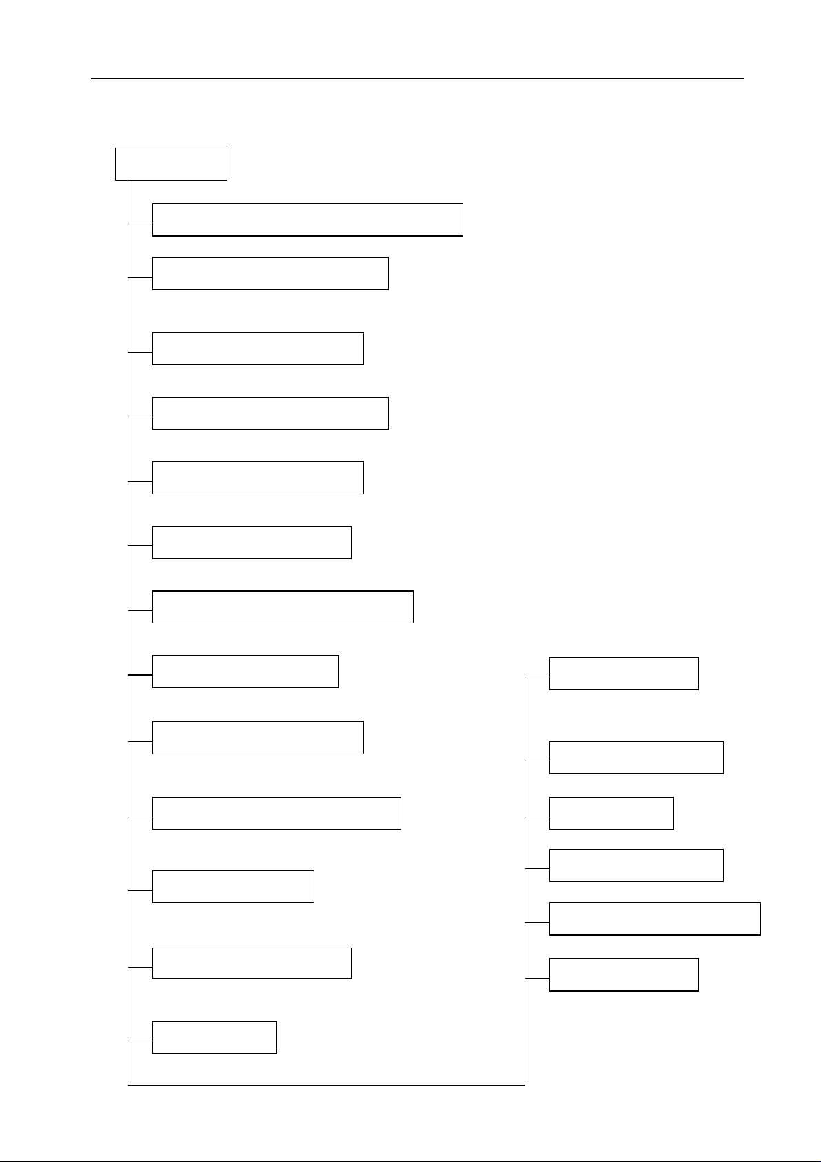
2. Function
Indoor unit
Operation ON/OFF by remote controller
Sensing by room temperature
Pipe temperature sensor.
Room temperature control
Starting temperature control
Service manual
Time Delay Safety control
Indoor fan speed control
Operation indication Lamps (LED)
Two-direction air vane
Sleep mode auto control
The unit will be turn off after seven hours.
Independent dehumidification
springtime or damp areas.
Self-diag. function
Anti-cold function
the beginning of unit start.
Temp. Compensation
Defrost mode
Auto-restart function
operate in any operation
Air flow Direction control
down automatically
Auto mode
- 3 -
Flexible wiring connection
Easy clean panel
Page 6
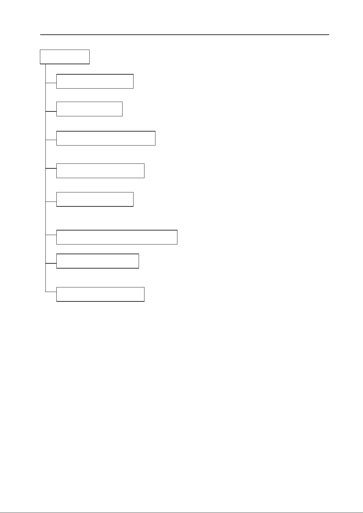
T
he unit can operate in cooling mode at low
ambient
temperature conditions.
The unit has
3 mins delay between
continuously
ON/OFF
operations
.
Outdoor unit
B
ird tail propeller fan makes the outdoor unit run more quietly.
T
he hydrophilic fin can improve the heating efficiency at operation mode.
I
t is only operated in the heating operation mode except defrosting
operation
.
Made from
electrolytic zinc steel sheet and anti
-
rust coated components.
I
t protects the valves and prevents water from dripping.
Power relay control
Low ambient kit
Low noise air flow system
Hydrophilic aluminum fin
4 way valve control
Service manual
Discharge pipe temperature protect
Anti-rust cabinet
Valve protection cover
- 4 -
Page 7
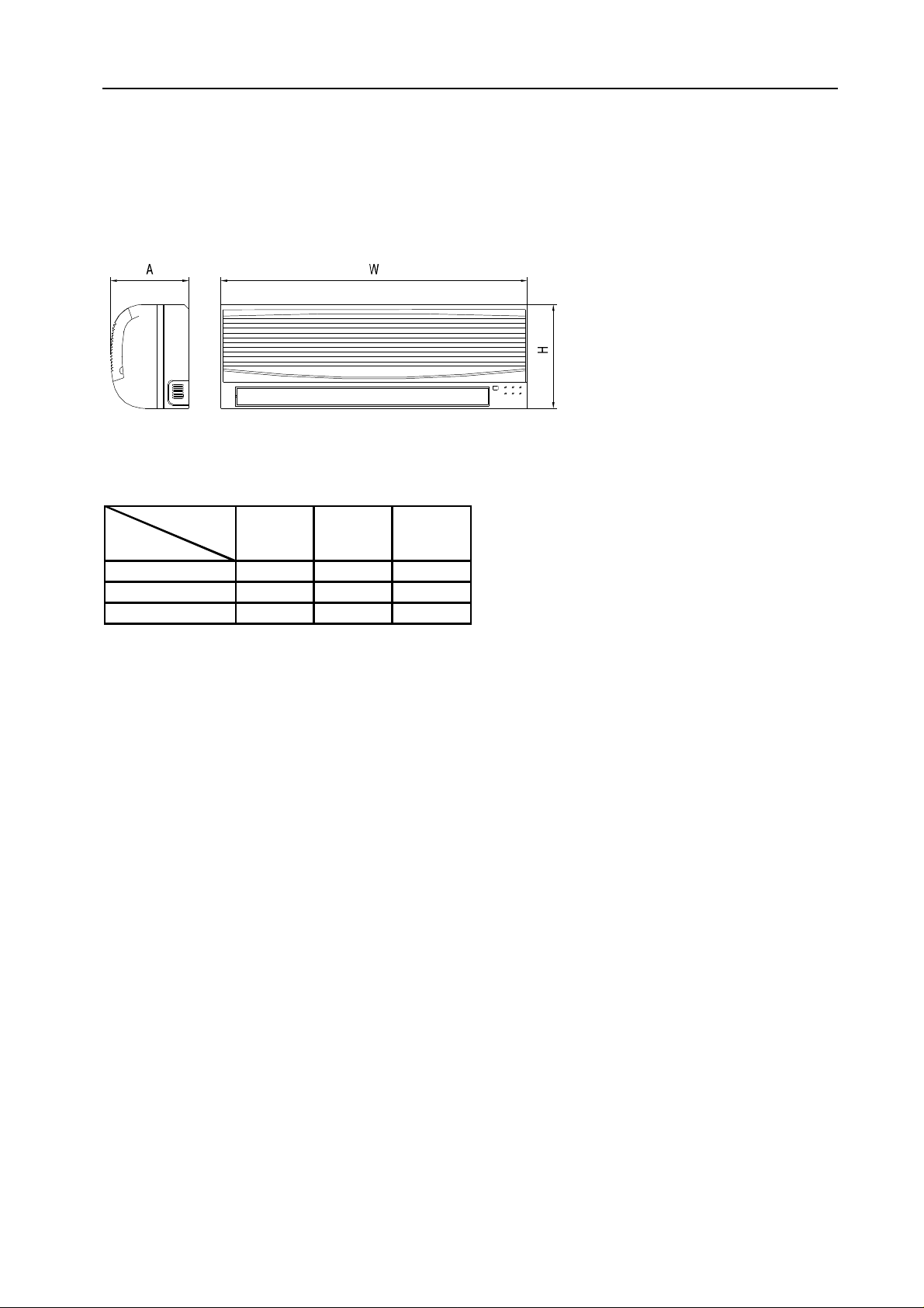
3. Dimension
3.1 Indoor unit
Service manual
Dimension
Mode
24K 1080 330 222
30K 1080 330 222
36K 1250 325 230
W H L
- 5 -
Page 8
560
360
735
560
360
735
560
360
735
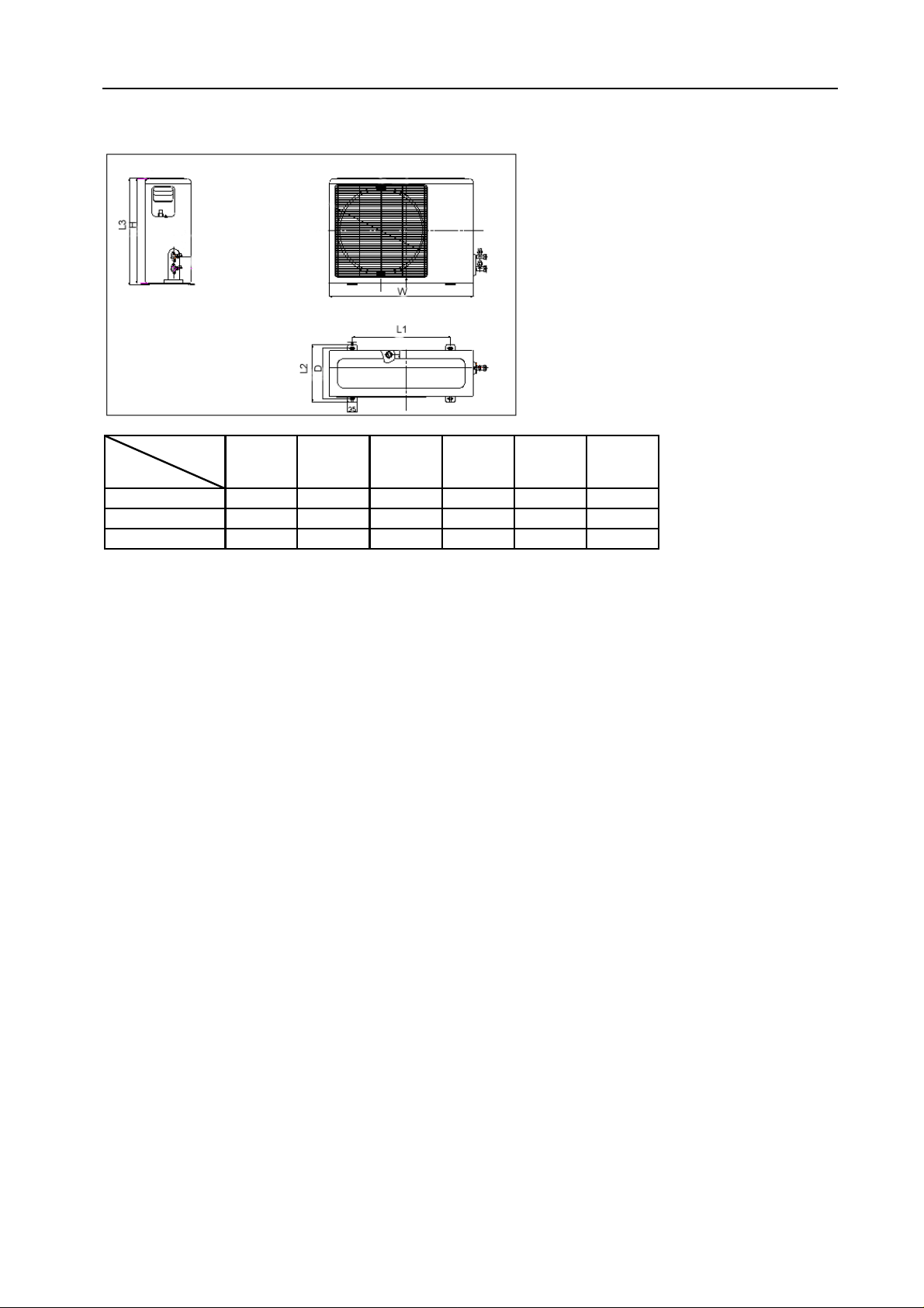
3.2 Outdoor unit
Service manual
Dimension
Mode
24K 845 695 335
30K 845 695 335
36K 895 860 302
W H D L1 L2 L3
- 6 -
Page 9
Ph-V-Hz
1, 220-240V~,50Hz
1, 220-240V~,50Hz
m3/h
≤56≤
Ф
Ф
m
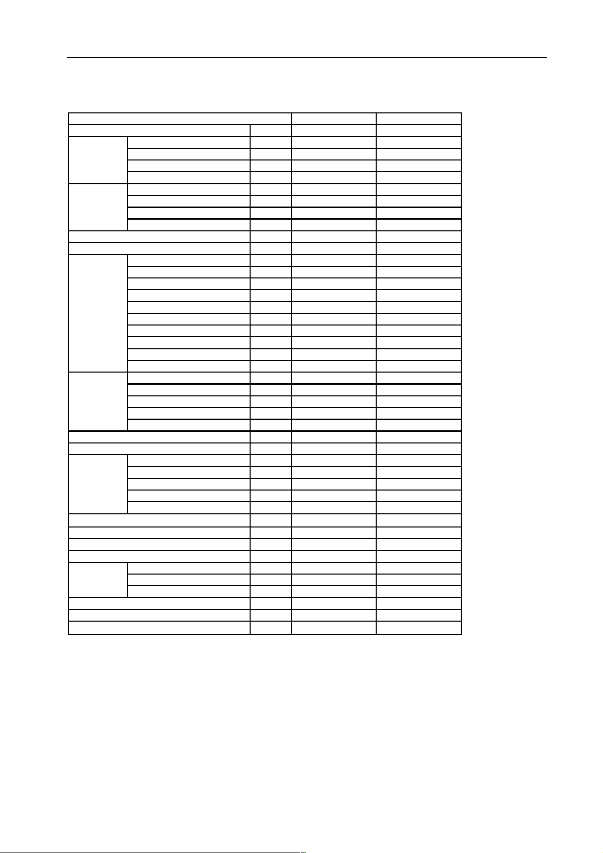
4. Specification
Service manual
Model
Power supply
Capacity Btu/h
Cooling
Input W
Rated current A
EER Btu/w.h
Capacity Btu/h
Heating
Input W
Rated current A
COP W/W
Max. current
Starting current
Model
Type
Brand
Capacity Btu/h
Compressor
Input W
Rated current(RLA) A
Locked rotor Amp(LRA) A
Thermal protector
Capacitor uF
Refrigerant oil ml
Model
Indoor
fan motor
Brand
Input W
Capacitor uF
Speed(hi/mi/lo) r/min
Indoor air flow (Hi/Mi/Lo)
Indoor noise level (Hi/Mi/Lo)
Model
Outdoor
fan motor
Brand
Input W
Capacitor uF
Speed r/min
Outdoor air flow
Outdoor noise level
Refrigerant type R410A
Design pressure
Refrigerant
piping
Liquid side/ Gas side mm
Max. refrigerant pipe length m
Max. difference in level m
Operation temp
Ambient temp
Application area
A
A
m3/h
dB(A)
dB(A)
g
MPa
℃
℃
2
MSG-24CR MSG-24HR
24000 24000
2750 2750
12.5 12.5
8.7, 2.6 8.7, 2.6
-----
----- 2750
-----
----- 2.9
16 16
50 50
QP407PT24C QP407PT24C
Rotary Rotary
LG LG
23400 23400
2317 2317
10.1 10.1
54 54
Internal Internal
45 45
650 650
YDK36-4G YDK36-4G
Welling Welling
65/63/60 65/63/60
2μF/450V 2μF/450V
1050/950/850 1050/950/850
1050/950/850 1050/950/850
43/40/37 43/40/37
YDK53-6K YDK53-6K
Welling Welling
130 130
3.5 3.5
800 800
2500 2500
R22/1850 R22/1900
2.6 2.6
9.53/Ф16.0
20 20
10 10
17-30 17-30
18-45 -7 - 45
40~56 40~56
27000
12.5
56
9.53/Ф16.0
Note:
- 7 -
The noise date is base on hemi-anechoic chamber, during actual operation; these values are normally somewhat
different as a result of ambient condition.
The above design and specifications are subject to change without prior notice for product improvement.
Page 10
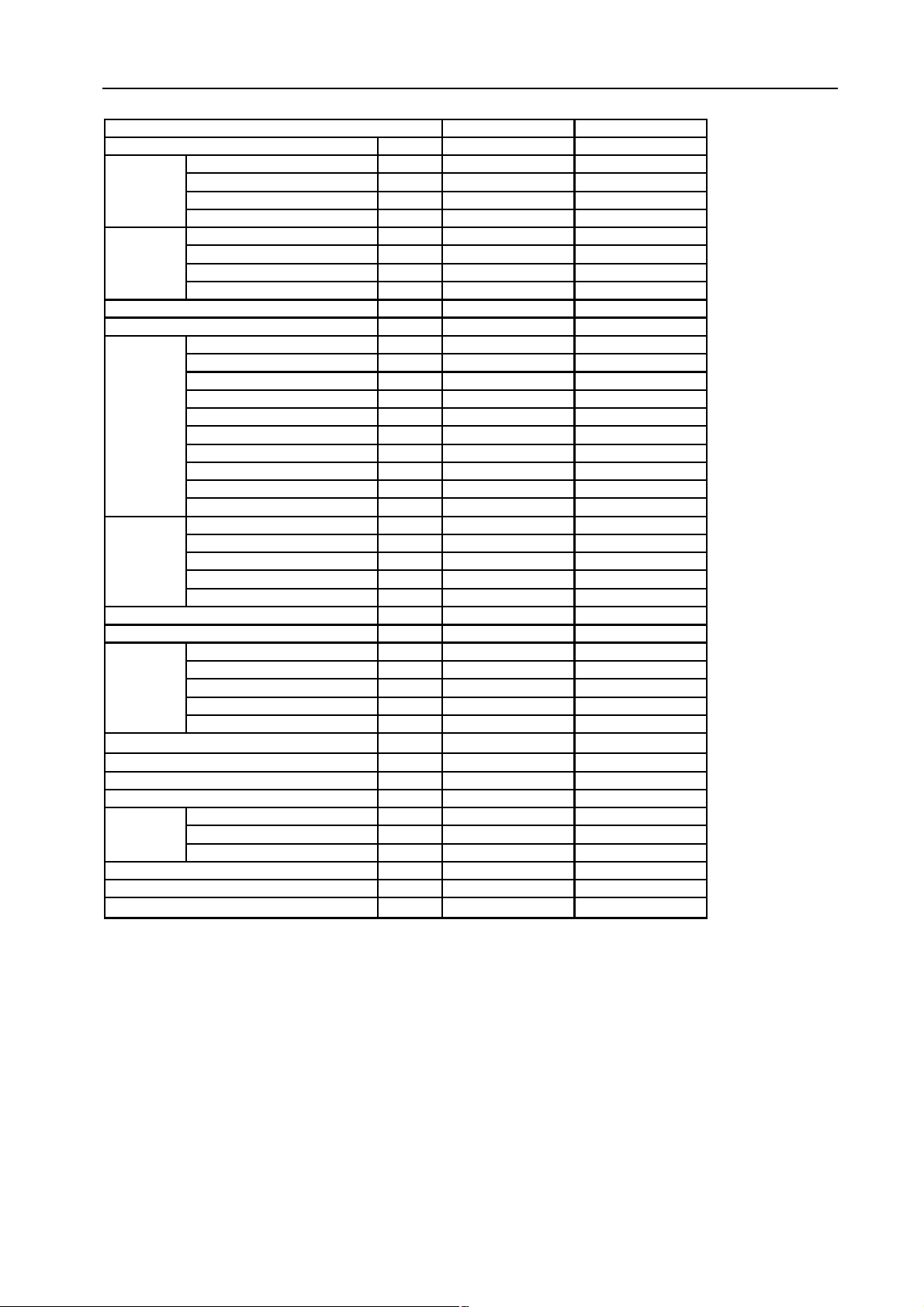
Service manual
Ph-V-Hz
1, 220-240V~,50Hz
1, 220-240V~,50Hz
m3/h
≤58≤
Ф
Ф
m
Model
Power supply
Capacity Btu/h 28000 28000
Cooling
Input W 3200 3200
Rated current A 15 15
EER Btu/w.h 8.8 8.8
Capacity Btu/h
Heating
Input W ----- 3100
Rated current A
COP W/W ----- 9.7
Max. current
Starting current
Model ZR34KH-PFJ-522 ZR34KH-PFJ-522
Type Scroll Scroll
Brand Copeland Copeland
Capacity Btu/h 28800 28800
Compressor
Input W 2520 2520
Rated current(RLA) A 12.1 12.1
Locked rotor Amp(LRA) A 76 76
Thermal protector Internal Internal
Capacitor uF 50 50
Refrigerant oil ml 1242 1242
Model
Indoor
fan motor
Brand Welling Welling
Input W 68/65/62 68/65/62
Capacitor uF
Speed(hi/mi/lo) r/min 1150/1050/950 1150/1050/950
Indoor air flow (Hi/Mi/Lo)
Indoor noise level (Hi/Mi/Lo)
Model YDK53-6K YDK53-6K
Outdoor
fan motor
Brand Welling Welling
Input W 140 140
Capacitor uF 3.5 3.5
Speed r/min 800 800
Outdoor air flow
Outdoor noise level
Refrigerant type R410A
Design pressure
Refrigerant
piping
Liquid side/ Gas side mm
Max. refrigerant pipe length m 20 20
Max. difference in level m 10 10
Operation temp
Ambient temp
Application area
MSG-30CR MSG-30HR
-----
-----
30000
14.5
A 20 20
A 76 76
YDK36-4G YDK36-4G
3μF/450V 3μF/450V
m3/h 1150/1050/950 1150/1050/950
dB(A) 47/44/41 47/44/41
2500 2500
dB(A)
58
g R22/2250 R22/2450
MPa 2.6 2.6
℃
℃
9.53/Ф16.0
17-30 17-30
2
18-45 -7 - 45
50~68 50~68
9.53/Ф16.0
Note:
- 8 -
The noise date is base on hemi-anechoic chamber, during actual operation; these values are normally somewhat
different as a result of ambient condition.
The above design and specifications are subject to change without prior notice for product improvement.
Page 11

Service manual
Ph-V-Hz
≥
m3/h
Φ
Φ
m
Model
Power supply
Capacity Btu/h
Cooling
Input W
Rated current A
EER Btu/w.h
Capacity Btu/h
Heating
Input W -----
Rated current A
COP W/W ----- 9.3
Max. current
Starting current
Model
Type
Brand
Capacity Btu/h
Compressor
Input W
Rated current(RLA) A
Locked rotor Amp(LRA) A
Thermal protector 15HM1637 15HM1637
Capacitor uF 60uF/
Refrigerant oil ml 1240 1240
Model
Indoor
fan motor
Brand Welling Welling
Input W
Capacitor uF 3 3
Speed(hi/mi/lo) r/min 1260/1150/990 1260/1150/990
Indoor air flow (Hi/Mi/Lo)
Indoor noise level (Hi/Mi/Lo)
Model YDK100-6 YDK100-6
Outdoor
fan motor
Brand Welling Welling
Input W 169 169
Capacitor uF 5 5
Speed r/min 900 900
Outdoor air flow
Outdoor noise level
Refrigerant type R410A
Design pressure
Refrigerant
piping
Liquid side/ Gas side mm
Max. refrigerant pipe length m 25 25
Max. difference in level m 10 10
Operation temp
Ambient temp
Application area
MSG-36CR MSG-36HR
1, 220-240V~, 50Hz 1, 220-240V~, 50Hz
35000 35000
4120 4120
18.6 18.6
8.5 8.5
-----
-----
38000
4100
18.5
A 32 32
A 150 150
ZR47K3-PFJ-522 ZR47K3-PFJ-522
SCROLL SCROLL
COPELAND COPELAND
39000 39000
3510 3510
19.3 19.3
114 114
400VAC 60uF/≥400VAC
YDK50-4E YDK50-4E
85/80/77 85/80/77
m3/h 1350/1200/1050 1350/1200/1050
dB(A)
49/46/42 49/46/42
3000 3000
dB(A) 59 59
g 2400 2450
MPa 2.6 2.6
℃
℃
9.52/Φ16
17-30 17-30
2
18-45 -7 - 45
60~78 60~78
9.52/Φ16
Note:
The noise date is base on hemi-anechoic chamber, during actual operation; these values are normally somewhat
different as a result of ambient condition.
The above design and specifications are subject to change without prior notice for product improvement.
- 9 -
Page 12

Service manual
Ph-V-Hz
3Ph,380-420V,50Hz
3Ph,380-420V,50Hz
m3/h
≤58≤
Ф
Ф
m
Model
Power supply
Capacity Btu/h 28000 28000
Cooling
Input W 3000 3000
Rated current A 5.3 5.3
EER Btu/w.h 9.3 9.3
Capacity Btu/h
Heating
Input W ----- 3000
Rated current A
COP W/W ----- 10.7
Max. current
Starting current
Model ZR34KH-TFD-522 ZR34KH-TFD-522
Type Scroll Scroll
Brand Copeland Copeland
Capacity Btu/h 28000 28000
Compressor
Input W 2480 2480
Rated current(RLA) A 4.6 4.6
Locked rotor Amp(LRA) A 40 40
Thermal protector Internal Internal
Capacitor uF ----- -----
Refrigerant oil ml 1242 1242
Model
Indoor
fan motor
Brand Welling Welling
Input W 72/67/63 72/67/63
Capacitor uF
Speed(hi/mi/lo) r/min 1150/1060/960 1150/1060/960
Indoor air flow (Hi/Mi/Lo)
Indoor noise level (Hi/Mi/Lo)
Model YDK53-6K YDK53-6K
Outdoor
fan motor
Brand Welling Welling
Input W 140 140
Capacitor uF 3.5 3.5
Speed r/min 800 800
Outdoor air flow
Outdoor noise level
Refrigerant type R410A
Design pressure
Refrigerant
piping
Liquid side/ Gas side mm
Max. refrigerant pipe length m 20 20
Max. difference in level m 10 10
Operation temp
Ambient temp
Application area
MSG-30CR MSG-30HR
-----
-----
32000
5.3
A 7 7
A 40 40
YDK36-4G YDK36-4G
3μF/450V 3μF/450V
m3/h 1150/1050/950 1150/1050/950
dB(A) 47/44/41 47/44/41
2500 2500
dB(A)
58
g R22/2250 R22/2450
MPa 2.6 2.6
℃
℃
9.53/Ф16.0
17-30 17-30
2
18-45 -7 - 45
50~68 50~68
9.53/Ф16.0
Note:
- 10 -
The noise date is base on hemi-anechoic chamber, during actual operation; these values are normally somewhat
different as a result of ambient condition.
The above design and specifications are subject to change without prior notice for product improvement.
Page 13

Service manual
m3/h
Φ
Φ
m
Model
Power supply
Capacity Btu/h
Cooling
Input W
Rated current A
EER Btu/w.h
Capacity Btu/h
Heating
Input W
Rated current A
COP W/W
Max. current
Starting current
Model
Type
Brand
Capacity Btu/h
Compressor
Input W
Rated current(RLA) A
Locked rotor Amp(LRA) A
Thermal protector
Capacitor uF
Refrigerant oil ml
Model
Indoor
fan motor
Brand
Input W
Capacitor uF
Speed(hi/mi/lo) r/min
Indoor air flow (Hi/Mi/Lo)
Indoor noise level (Hi/Mi/Lo)
Model
Outdoor
fan motor
Brand
Input W
Capacitor uF
Speed r/min
Outdoor air flow
Outdoor noise level
Refrigerant type R410A
Design pressure
Refrigerant
piping
Liquid side/ Gas side mm
Max. refrigerant pipe length m
Max. difference in level m
Operation temp
Ambient temp
Application area
Ph-V-Hz
A
A
m3/h
dB(A)
dB(A)
g
MPa
℃
℃
2
MSG-36CR MSG-36HR
3, 380-420V~, 50Hz3, 380-420V~, 50Hz
35000 35000
4120 4120
6.5 6.5
8.5 8.5
-----
-----
-----
----- 9.3
11 11
48 48
ZR34KH-TFD-522 ZR34KH-TFD-522
Scroll Scroll
Copeland Copeland
39000 39000
3480 3480
6.3 6.3
43/48 43/48
34HM224 34HM224
----- -----
SONTEX 200LT 1242 SONTEX 200LT 1242
YDK50-4E YDK50-4E
Welling Welling
85/80/77 85/80/77
3 3
1260/1150/990 1260/1150/990
1350/1200/1050 1350/1200/1050
49/46/42 49/46/42
YDK100-6 YDK100-6
Welling Welling
169 169
5 5
900 900
3000 3000
59 59
2400 2450
2.6 2.6
9.52/Φ16
25 25
10 10
17-30 17-30
18-45 -7 - 45
60~78 60~78
38000
4100
6.4
9.52/Φ16
Note:
The noise date is base on hemi-anechoic chamber, during actual operation; these values are normally somewhat
different as a result of ambient condition.
The above design and specifications are subject to change without prior notice for product improvement.
- 11 -
Page 14

Service manual
5. Refrigerant cycle diagram
Ø Cooling only
Ø Heat pump mode
- 12 -
Page 15

Service manual
7. Schematic diagram and Wiring diagram
7.1 Schematic diagram
- 15 -
Page 16

7.2.2 Heating mode
MSG-24HR, MSG-30HR
Service manual
A2
A1
- 18 -
Page 17

MSG-36HR
Service manual
A1A2
- 19 -
Page 18

7.2.3 Cooling mode (3 Ph)
MSG-30CR (3ph)
Service manual
- 20 -
Page 19

7.2.4 Heating mode (3 Ph)
MSG-30HR (3ph)
Service manual
1
2
4
6
73
5
- 22 -
Page 20

MSG-36HR (3ph)
Service manual
- 23 -
Page 21

Service manual
length
Btu/h
GAS
LIQUID
B (m)A
(m)
(g/m)
3/8’’ (φ9.52)
1/4’’ (φ6.35)
5510301/2’’ (φ12.7)
1/4’’ (φ6.35)
5510301/2’’ (φ12.7)
1/4’’ (φ6.35)
5815305/8’’ (φ15.88)
1/4’’ (φ6.35)
51020305/8’’ (φ15.88)
3/8’’ (φ9.52)
51020655/8’’ (φ15.88)
3/8’’ (φ9.52)
51530653/4’’ (φ19.05)
3/8’’ (φ9.52)
51530
65
8. Installation details
8.1 Wrench torque sheet for installation
Outside diameter
mm inch Kg.m
φ6.35 1/4 1.8
φ9.52 3/8 4.2
φ12.7 1/2 5.5
φ15.88 5/8 6.6
φ19.05 3/4 6.6
Torque
8.2 Connecting the cables
The power cord of connect should be selected according to the following specifications sheet.
Grade
Unit 7K 9K 12K 18K 24K 28K
mm2 1.0 1.0 1.5 2.5 2.5 2.5
8.3 Pipe length and the elevation
Capacity
7k~12K
Standard
Pipe size
(m) Elevation Elevation refrigerant
Max. Max. Additional
16K~28K
30K~36K
In case that
more than
Caution:
Capacity is base on standard length and maximum allowance length is base of reliability.
Oil trap should be install per 5-7 meters.
- 24 -
Page 22

Service manual
8.4 Air purging of the piping and indoor unit
Required tools:
Hexagonal wrench; adjustable wrench; torque wrenches, wrench to hold the joints and gas leak
detector.
Note:
The air in the indoor unit and in the piping must be purged. If air remains in the refrigeration piping, it
will affect the compressor, reduce the cooling capacity, and could lead to a malfunction of unit.
Be sure, using a torque wrench to tighten the service port cap (after using the service port), so that it
prevents the gas leakage from the refrigeration cycle.
Procedure
1. Recheck the piping connections.
2. Open the valve stem of the 2-way valve
counterclockwise approximately 90’, wait
10 seconds, and then set it to closed
position.
§ Be sure to use a hexagonal wrench to operate
the valve stem
3. Check for gas leakage.
§ Check the flare connection for gas leakage
4. Purge the air from the system.
§ Set the 2-way valve to the open position and
remove the cap from the 3-way valve’s
service port.
§ Using the hexagonal wrench to press the
valve core pin, discharge for three seconds
and then wait for one minute.
5. Use torque wrench to tighten the service
port cap to a torque of 1.8 kg.m. (18n.m)
6. Set the 3-way valve to the opened
position.
- 25 -
7. Mounted the valve stem nuts to the 2-way
and 3-way valves.
8. Check for gas leakage.
§ At this time, especially check for gas leakage
from the 2-way and 3-way stem nuts, and
from the service port.
Caution:
If gas leakage is discovered in step (3) above,
take the following measures.
If the leaks stop when the piping connections
are tightened further, continue working from
step (4).
If the gas leaks do not stop when the
connections are retightened, repair the location
of the leak, discharge all of the gas through the
service port, and then recharge with the
specified amount of gas from a gas cylinder.
Page 23

8.5 Pumping down (Re-installation)
Service manual
Procedure
1. Confirm that both the 2-way and 3-way valves are set to the opened position.
§ Remove the valve stem caps and confirm that the valve stems are in the opened position.
§ Be sure to use a hexagonal wrench to operate the valve stems.
2. Operate the unit for 10 to 15 minutes.
3. Stop operation and wait for 3 minutes, then connect the charge set to the service port of the
3-way valve.
§ Connect the charge hose with the push pin to the gas service port.
4. Air purging of the charge hose.
§ Open the low-pressure valve on the charge set slightly to purge air from the charge hose.
5. Set the 2-way valve to the close position.
6. Operate the air conditioner at the cooling cycle and stop it when the gauge indicates 0.1MPa.
7. Immediately set the 3-way valve to the closed position.
§ Do this quickly so that the gauge ends up indicating 0.3 to 0.5Mpa.
8. Disconnect the charge set, and amount the 2-way and 3-way valve’s stem nuts and service
port caps.
§ Use a torque wrench to tighten the service port cap to a torque of 1.8 kg.m.
§ Be sure to check for gas leakage.
- 26 -
Page 24

8.6 Re-air purging (Re-installation)
Service manual
Procedure:
1. Confirm that both the 2-way and 3-way valves are set to the closed position.
2. Connect the charge set and a charging cylinder to the service port of the 3-way valve.
§ Leave the valve on the charging cylinder closed.
3. Air purging.
§ Open the valves on the charging cylinder and the charge set. Purge the air by loosening the flare nut
on the 2-way valve approximately 45’ for 3 seconds then closing it for 1 minutes; repeat 3 times.
§ After purging the air, use a torque wrench to tighten the flare nut to on the 2-way valve.
4. Check the gas leakage.
§ Check the flare connections for gas leakage.
5. Discharge the refrigerant.
§ Close the valve on the charging cylinder and discharge the refrigerant until the gauge indicate 0.3 to
0.5 Mpa.
6. Disconnect the charge set and the charging cylinder, and set the 2-way and 3-way valves to
the open position.
§ Be sure to use a hexagonal wrench to operate the valve stems.
7. Mount the valve stems nuts and the service port cap.
§ Be sure to use a torque wrench to tighten the service port cap to a torque 18N.m.
§ Be sure to check the gas leakage.
- 27 -
Page 25

Service manual
8.7 Balance refrigerant of the 2-way, 3-way valves
Procedure:
1. Confirm that both the 2-way and 3-way valves are set to the open position.
2. Connect the charge set to the 3-way valve’s service port.
§ Leave the valve on the charge set closed.
§ Connect the charge hose with the push pin to the service port.
3. Open the valves (Low side) on the charge set and discharge the refrigerant until the gauge
indicates 0.05 to 0.1 Mpa.
§ If there is no air in the refrigeration cycle [the pressure when the air conditioner is not running is
higher than 0.1Mpa, discharge the refrigerant until the gauge indicates 0.05 to 0.1 Mpa. If this is the
case, it will not be necessary to apply a evacuation.
§ Discharge the refrigeration gradually; if it is discharged too suddenly, the refrigeration oil sill be
discharged.
- 28 -
Page 26

8.8 Evacuation
Service manual
Procedure:
1. Connect the vacuum pump to the charge set’s centre hose.
2. Evacuation for approximately one hour.
§ Confirm that the gauge needle has moved toward -0.1 Mpa (-76 cmHg) [vacuum of 4 mmHg or less].
3. Close the valve (Low side) on the charge set, turn off the vacuum pump, and confirm that the
gauge needle does not move (approximately 5 minutes after turning off the vacuum pump).
4. Disconnect the charge hose from the vacuum pump.
§ Vacuum pump oil, if the vacuum pump oil becomes dirty or depleted, replenish as needle.
- 29 -
Page 27

8.9 Gas charging
Service manual
Procedure:
1. Connect the charge hose to the charging cylinder.
§ Connect the charge hose which you disconnected from the vacuum pump to the valve at the bottom
of the cylinder.
2. Purge the air from the charge hose.
§ Open the valve at the bottom of the cylinder and press the check valve on the charge set to purge the
air (be careful of the liquid refrigerant).
3. Open the valves (Low side) on the charge set and charge the system with liquid refrigerant.
§ If the system cannot be charge with the specified amount of refrigerant, if can be charged with a little
at a time (approximately 150g each time0 while operating the air conditioner in the cooling cycle;
however, one time is not sufficient, wait approximately 1 minute and then repeat the
procedure.(pumping down-pin).
4. Immediately disconnect the charge hose from the 3-way valve’s service port.
§ Stopping partway will allow the refrigerant to be discharged.
§ If the system has been charged with liquid refrigerant while operating the air conditioner, turn off the
air conditioner before disconnecting the hose.
5. Mounted the valve stem caps and the service port
§ Use torque wrench to tighten the service port cap to a torque of 18N.m.
§ Be sure to check for gas leakage.
- 30 -
Page 28

9. Capacity table
Cooling mode
Conditions
21ºC D
Total capacity kW
6.76
6.35
5.88
5.41
5.05
4.69
15ºC W
Sensitive capacity kW
4.93
4.74
4.44
4.11
3.86
3.61
24ºC D
Total capacity kW
7.31
6.99
6.53
6.17
5.75
5.30
17ºC W
Sensitive capacity kW
5.38
5.21
4.96
4.72
4.43
4.11
27ºC D
Total capacity kW
7.79
7.44
6.64
6.19
5.71
19ºC W
Sensitive capacity kW
5.92
5.73
5.22
4.88
4.51
2.97
3.30
3.41
32ºC D
Total capacity kW
8.68
8.32
8.05
7.49
6.84
6.45
23ºC W
Sensitive capacity kW
6.68
6.49
6.32
5.91
5.47
5.22
-7ºC D
-8ºC W
7.91
2.75
9.1 MSG-24CR
SUMMER
Indoor
Input kW. 2.35 2.48 2.59 2.79 3.10 3.21
Input kW. 2.43 2.56 2.67 2.88 3.20 3.31
Input kW. 2.50 2.64
Input kW. 2.60 2.75 2.86 3.09 3.43 3.55
9.2 MSG-24HR
SUMMER
Indoor
Service manual
OUTDOOR TEMPERATURE DRY
25ºC 30ºC 35ºC 40ºC 45ºC 50ºC
7.03
5.48
2.75
OUTDOOR TEMPERATURE DRY
25ºC 30ºC 35ºC 40ºC 45ºC 50ºC
WINTER
Indoor
Conditions
15ºC
18ºC
20ºC
22ºC
Input kW. 2.35 2.48 2.59 2.79 3.10 3.21
Input kW. 2.43 2.56 2.67 2.88 3.20 3.31
7.03
5.48
Input kW. 2.50 2.64
Input kW. 2.60 2.75 2.86 3.09 3.43 3.55
OUTDOOR CONDITIONS
Capacity kW
Input kW.
Capacity kW
Input kW.
Capacity kW
Input kW.
Capacity kW
Input kW.
12ºC D
11ºC W
9.33 8.19 7.50 6.58 5.67 4.98
2.95 2.68 2.50 2.31 2.01 1.83
9.16 8.04 7.31 6.35 5.38 4.66
3.03 2.73 2.53 2.37 2.07 1.85
9.08
3.11
9.00 7.82 7.12 6.10 5.01 4.15
3.22 2.78 2.65 2.51 2.27 2.03
7ºC D
6ºC W
2.75
4ºC D
3ºC W
7.23 6.19 5.09 4.22
2.61 2.42 2.13 1.95
0ºC D
-1ºC W
-4ºC D
-6ºC W
- 31 -
Page 29

Cooling mode
Conditions
21ºC D
Total capacity kW
7.88
7.40
6.86
6.31
5.90
5.47
15ºC W
Sensitive capacity kW
5.75
5.52
5.18
4.79
4.50
4.21
24ºC D
Total capacity kW
8.53
8.15
7.62
7.20
6.71
6.19
17ºC W
Sensitive capacity kW
6.27
6.07
5.79
5.51
5.17
4.79
27ºC D
Total capacity kW
9.09
8.68
7.75
7.22
6.66
19ºC W
Sensitive capacity kW
6.91
6.69
6.08
5.69
5.26
3.46
3.84
3.97
32ºC D
Total capacity kW
10.12
9.71
9.39
8.73
7.98
7.52
23ºC W
Sensitive capacity kW
7.79
7.57
7.37
6.90
6.38
6.09
-7ºC D
-8ºC W
8.79
3.10
9.3 MSG-30CR
SUMMER
Indoor
9.4 MSG-30HR
SUMMER
Indoor
Service manual
OUTDOOR TEMPERATURE DRY
25ºC 30ºC 35ºC 40ºC 45ºC 50ºC
Input kW. 2.74 2.89 3.01 3.25 3.61 3.73
Input kW. 2.82 2.98 3.10 3.35 3.72 3.85
8.20
6.40
Input kW. 2.91 3.07
Input kW. 3.03 3.19 3.33 3.59 3.99 4.13
OUTDOOR TEMPERATURE DRY
25ºC 30ºC 35ºC 40ºC 45ºC 50ºC
3.20
WINTER
Indoor
Conditions
15ºC
18ºC
20ºC
22ºC
Input kW. 2.74 2.89 3.01 3.25 3.61 3.73
Input kW. 2.82 2.98 3.10 3.35 3.72 3.85
8.20
6.40
Input kW. 2.91 3.07
Input kW. 3.03 3.19 3.33 3.59 3.99 4.13
OUTDOOR CONDITIONS
Capacity kW
Input kW.
Capacity kW
Input kW.
Capacity kW
Input kW.
Capacity kW
Input kW.
12ºC D
11ºC W
10.37 9.10 8.33 7.31 6.30 5.53
3.33 3.03 2.81 2.60 2.27 2.06
10.18 8.93 8.13 7.06 5.98 5.18
3.41 3.07 2.86 2.67 2.33 2.09
10.09
3.51
10.00 8.69 7.91 6.78 5.56 4.61
3.63 3.13 2.99 2.83 2.55 2.29
7ºC D
6ºC W
3.20
4ºC D
3ºC W
8.03 6.88 5.66 4.69
2.95 2.73 2.41 2.20
0ºC D
-1ºC W
-4ºC D
-6ºC W
- 32 -
Page 30

Cooling mode
Conditions
21ºC D
Total capacity kW
9.87
9.27
8.59
7.90
7.38
6.85
15ºC W
Sensitive capacity kW
7.21
6.92
6.48
6.00
5.64
5.28
24ºC D
Total capacity kW
10.69
10.21
9.54
9.02
8.41
7.75
17ºC W
Sensitive capacity kW
7.85
7.61
7.25
6.90
6.47
6.00
27ºC D
Total capacity kW
11.38
10.88
9.71
9.05
8.34
19ºC W
Sensitive capacity kW
8.65
8.37
8.01
7.62
7.13
6.59
4.45
4.94
5.11
32ºC D
Total capacity kW
12.68
12.16
11.76
10.94
10.00
9.42
23ºC W
Sensitive capacity kW
9.76
9.48
9.23
8.64
8.00
7.63
-7ºC D
-8ºC W
11.14
4.12
9.5 MSG-36CR
SUMMER
Indoor
Service manual
OUTDOOR TEMPERATURE DRY
25ºC 30ºC 35ºC 40ºC 45ºC 50ºC
Input kW. 3.52 3.72 3.87 4.18 4.65 4.80
Input kW. 3.64 3.84 4.00 4.32 4.80 4.96
10.27
9.6 MSG-36HR
SUMMER
Indoor
WINTER
Indoor
Conditions
15ºC
18ºC
20ºC
22ºC
Input kW. 3.75 3.96
Input kW. 3.90 4.11 4.28 4.63 5.14 5.31
OUTDOOR TEMPERATURE DRY
25ºC 30ºC 35ºC 40ºC 45ºC 50ºC
Input kW. 3.52 3.72 3.87 4.18 4.65 4.80
Input kW. 3.64 3.84 4.00 4.32 4.80 4.96
Input kW. 3.75 3.96
Input kW. 3.90 4.11 4.28 4.63 5.14 5.31
OUTDOOR CONDITIONS
Capacity kW
Input kW.
Capacity kW
Input kW.
Capacity kW
Input kW.
Capacity kW
Input kW.
12ºC D
11ºC W
13.14 11.53 10.56 9.27 7.98 7.01
4.42 4.02 3.74 3.46 3.02 2.73
12.90 11.32 10.30 8.94 7.58 6.56
4.53 4.08 3.80 3.55 3.10 2.78
12.79
4.66
12.67 11.02 10.03 8.59 7.05 5.84
4.83 4.16 3.97 3.77 3.40 3.04
7ºC D
6ºC W
4.12
10.27
4.12
4ºC D
3ºC W
10.18 8.72 7.17 5.95
3.91 3.63 3.20 2.93
0ºC D
-1ºC W
-4ºC D
-6ºC W
- 33 -
Page 31

11. Model and Parameters
Service manual
Model
I3SEC [A]
I5MIN [A]
IFAN [A]
IDEFROST [A]
TE1 ['C]
TE2 ['C]
TE3 ['C]
TE4 ['C]
TE5 ['C]
TE6 ['C]
TE7 ['C]
TE8 ['C]
TE9 ['C]
TE10 ['C]
TE11 ['C]
TE14 ['C]
TE16 ['C]
3Ph 380~420V
Model
I3SEC [A]
I5MIN [A]
IFAN [A]
IDEFROST [A]
TE1 ['C]
TE2 ['C]
TE3 ['C]
TE4 ['C]
TE5 ['C]
TE6 ['C]
TE7 ['C]
TE8 ['C]
TE9 ['C]
TE10 ['C]
TE11 ['C]
TE14 ['C]
TE16 ['C]
MSG-24CR MSG-24HR MSG-30CR MSG-30HR MSG-36CR MSG-36HR
22 22 26 26 34 34
20 20 24 24 32 32
16 16 20 20 25 25
14 14 18 18 22 22
25 25 30
32 32 37
30 30 34
20 20 24
2 2 2 2 2 2
12 12 12 12 12 12
63 63 63
54 54 54
50 50 50
65 65 70
55 55 65
32 32 32
42 42 34
MSG-30CR MSG-30HR MSG-36CR MSG-36HR
26 26 34 34
24 24 32 32
20 20 25 25
18 18 22 22
25 30
32 37
30 34
20 24
2 2 2 2
12 12 12 12
63 63
54 54
50 50
65 70
55 65
32 32
42 34
- 42 -
Page 32

Service manual
12. Troubleshooting
12.1 Display board
§ Operation
The indicator flashes once every second after power is on and illuminates when the air conditioner is
in operation.
§ Timer indicator:
The indicator illuminates then TIMER is set ON.
§ PRE-DEF. indicator (For cooling & heating mode only)
The air conditioner starts defrosting automatically if outdoor unit frosts in heating operating.
At this time, PRE-DEF. indicator illuminates.
§ Auto indicator:
This indicator flashes when the air conditioner is in AUTO operation.
§ ECON indicator
This indicator illuminates while the air conditioner is in economic operation.
- 43 -
Page 33

lamp
lamp
Indoor fan speed has been out of control for over 1 minute
X
Indoor room temp. or evaporator sensor is open circuit or short circuit
On
Over current protection of the compressor occurs 4 times
X
EEROM error
On
No over-zero signal
Flash at 5Hz
lamp
lamp
lamp
Over current protection of the compressor occurs 4 times
X
Indoor fan speed has been out of control for over 1 minute
X
No over-zero signal
Temp. sensor on indoor evaporator is open circuit or short circuit
X
X
Indoor room temp. sensor is open circuit or short circuit
X
X
EEROM error
On
Xr Extinguish
Flash at 5Hz
12.2 Troubleshooting
For cooling mode:
Service manual
Failure phenomenon
r
Extinguish
For heat pump mode:
Failure phenomenon
Operation
Operation
Timer
Timer
Defrosting
- 44 -
Page 34

Service manual
12.3 Diagnostic chart
After energizing, no indicator is lighted and the air conditioner can’t be operated.
- 45 -
Page 35

Service manual
12.4 Resetting phenomenon often occurs during operation.
(That is automatically entering to the status when power is on.)
The reason is that the instantaneous voltage of main chip is less than 4.5V. Check according to the
following procedure:
Resetting phenomenon often occurs during operation.
Yes
After changing indoor PCB, check if the failure realease.
Yes
After changing indoor fan motor, check if the failure realease.
YES
Power supply circuit has problems.
Indoor PCB is defective.
12.5 Operation lamp flashes and Timer lamp off.
Yes
12.6 Operation lamp flashes and Timer lamp on.
- 46 -
Page 36

Service manual
12.7 Operation lamp off and Timer lamp flashes
12.8 Operation lamp on and Timer lamp flashes
EEROM error, indoor PCB is defective.
12.9 Operation lamp flashes, Timer lamp flashes .
This is alarm signal when the main chip can’t detect over-zero signal. When such failure occurs, the
main control board must have fault.
- 47 -
 Loading...