

Midea MS9V-18HRDN1-QC2(B) 9V, MS9V-24HRDN1-QC2W 9V, MS9V-09HRDN1-QC2 9V, MS9V-12HRDN1-QC2 9V Service Manual
Page 1

9VSI-1010-A
SERVICE MANUAL
MIDEA AIRCONDITIO NER
DC INVERTER
SPLIT WALL-MOUNTED TYPE
MS9V-18HRDN1-QC2(B)
MS9V-24HRDN1-QC2W
9V SERIES
Page 2

CONTENTS
1. Precaution .................................................................................................................................................... 1
1.1 Safety Precaution .......................................................................................................................... 1
1.2 Warning ......................................................................................................................................... 1
2. Function ........................................................................................................................................................ 6
3. Dimension .................................................................................................................................................... 8
3.1 Indoor Unit ..................................................................................................................................... 8
3.2 Outdoor Unit ................................................................................................................................ 10
4. Refrigerant Cycle Diagram ........................................................................................................................ 11
5. Wiring Diagram .......................................................................................................................................... 12
5.1 Indoor .......................................................................................................................................... 12
5.2 Outdoor Unit ................................................................................................................................ 13
6. Installation details ...................................................................................................................................... 14
6.1 Wrench torque sheet for installation ........................................................................................... 14
6.2 Connecting the cables ................................................................................................................ 14
6.3 Pipe length and the elevat ion ..................................................................................................... 14
6.4 Air pur ging with vacuum pump .................................................................................................... 15
6.5 Pumping down (Re-installation) .................................................................................................. 16
6.6 Re-air purging (Re-installation) ................................................................................................... 18
6.7 Balance refrigerant of t he 2-way, 3-way va lves .......................................................................... 19
6.8 Evacuation .................................................................................................................................. 20
6.9 Gas charging ............................................................................................................................... 21
7. Operation characteristics ......................................................................................................................... 22
8. Electronic function .................................................................................................................................... 23
8.1 Abbreviation ................................................................................................................................ 23
8.2 Display function ........................................................................................................................... 23
8.3 Main Protection ........................................................................................................................... 24
8.4 Operation Modes and Function s ................................................................................................. 25
9. Tr o u b leshooting ......................................................................................................................................... 37
9.1 Indoor Unit Error Display ............................................................................................................. 38
9.2 Diagnosis and Solution ............................................................................................................... 39
Page 3

1. Precaution
1.1 Safety Precaution
To prevent injury t o the user or other people a nd property damage, t he following
instructions must be followed.
Incorrect oper ation due to ignoring inst ruction will cause harm or damage.
Before service unit, be sure t o read this service manual at first.
1.2 Warning
Installation
Do not use a defective or under r ated circuit breaker. Use this appliance on a dedicat ed
circuit.
There is risk of fire or electric shock.
For electrical work, co ntact the dealer, seller , a qualified electrician, or an Authorized
service center.
Do not disassemble or repair the product, there is risk of fire or elect r ic shock.
Always ground the product.
There is risk of fire or electric shock.
Install the panel and the cover of control b ox securely.
There is risk of fire of electr ic shock.
Always install a dedicated circuit and breaker.
Improper wiring or inst allation may cause fore or electric shock.
Use the correctly r at ed breaker of fuse.
There is risk of fire or electr ic shock.
Do not modify or extend the power cable.
There is risk of fire or electr ic shock.
Do not install, remove, or reinstall the unit by yourself(customer).
There is risk of fire, electric s hock, explosion, or injury.
1
Page 4

2
Be caution whe n unpacking and installing the p roduct.
Sharp edges could cause inj ur y, be especially careful of the case edges and t he f ins on the
condenser and evaporat or.
For installati on, always contact the dealer or an Authorized service center.
There is risk of fire, electric s hock, explosion, or injury.
Do not inst a l l the product on a defect ive installation stand.
It may cause injury, accident, or damage t o t he pr oduct.
Be sure the install at i on area does not deteriorate with age.
If the base collapses, the air conditioner could fall with it, caus ing property damage, product failure,
and personal injury.
Do not let the air conditioner run for a long time when the humi dity is very high and a
door or a windo w is l e ft open.
Moisture may condense and wet or damage furniture.
Take care to ensure t hat power cable could not be pulled out or damaged during
operation.
There is risk of fire or electr ic shock.
Do not place anything on the power cable .
There is risk of fire or electr ic shock.
Do not plug or unplug t he power supply pl ug during operation.
There is risk of fire or electr ic shock.
Do not touch (operation) the product with wet hands.
There is risk of fire or electr ic shock.
Do not place a heater or other appliance near the power cable.
There is risk of fire and electric shock.
Do not allow water to run into electric parts.
It may cause fire, failure of the product, or electric shock.
Do not store or us e flammable gas or combustible near the pro duct.
There is risk of fire or failure of product.
Do not use the product in a tightly close d space for a long time.
Oxygen deficiency could occur.
When flammable gas leaks, turn off the gas and open a windo w f or ventilation before
Page 5

3
turn the product on.
Do not use the telephone or turn switches on or off.
There is risk of explosion or fire.
If strange sounds, or small or smoke comes from product. Turn the breaker off or
disconnect the power supply cable.
There is risk of electric shock or fire.
Stop operation and close the window in storm or hurricane. If possible, remove the
product from the window before the hurricane arrives.
There is risk of property dam age, failure of product, or electric shock.
Do not open the inl et gril l of the pro duct dur ing o perati on. ( Do not to uch the electr ost at ic
filter, if the unit is so equipped.)
There is risk of physical injury, electric shock, or product failure.
When the product i s soaked (flooded or s ubmerged), contact an Authorized service
center.
There is risk of fire or electr ic shock.
Be caution that water could not enter the product.
There is risk of fire, electric s hock, or product damage.
Ventilate the product from time to time when operating it together with a stove, etc.
There is risk of fire or electr ic shock.
Turn the main power off when cleaning or maintaining the product.
There is risk of electric shock.
When the product i s not be used for a long time, disconnect the power supply plug or
turn off the breaker.
There is risk of product damage or f ailure, or unintended operation.
T ake care to ensure that nobody coul d step on or fall onto the outdoor unit.
This could result in personal injury and product damage.
CAUTION
Always check for gas (refr i gerant) leakage after installation or repair of product.
Low refrigerant levels may cause failure of product.
Page 6

4
Install the drain hose to ensure that water i s drained away properly.
A bad co nnection may cause water leakage.
Keep level even when installing the product.
To avoided vibration of wat er leakage.
Do not inst a l l the product where the noise or hot ai r from the outdo or u n it could dam age
the neighborhoods.
It may cause a problem for your neighbors.
Use two or more people to lift and transport the product.
Avoid personal injury.
Do not install t he product where it will be exposed to se a wind (salt spray) directly.
It may cause corrosion on the product. Corro s i on, particularly on the condenser and evaporator fins,
could cause product malfunction or inefficient operat i on.
Operational
Do not expose th e sk i n directly to cool air f or long periods of time. (Do not sit in the
draft).
This could harm to your health.
Do not use the product for special purp oses, suc h as preserving fo ods, works of art, etc.
It is a consumer air condit i oner, not a precisio n refrigerant system.
There is risk of damage or loss of property.
Do not block the inlet or outlet of air flow.
It may cause product failu r e.
Use a soft cloth to cl ean. Do not use harsh detergents, solvents, etc.
There is risk of fire, electric s hock, or damage to the plastic parts of the product.
Do not touch the m etal parts of the product when r emoving the air filter. They are very
sharp.
There is risk of personal injury.
Do not step on or p ut anything on the prod uc t . (outdoor units)
There is risk of personal injury and f ai lur e of product.
Always insert the filt er securely. Clean the filter every two weeks or mor e often if
Page 7

5
necessary.
A dirty filter reduces the efficiency of the air conditioner and could cause product ma lfunction or
damage.
Do not insert ha nds or other object thro ugh air inlet or outlet while the product is
operated.
There are sharp and moving parts that could cause personal injury .
Do not drink the water drained from the product.
It is not sanitary could ca use serious health issues.
Use a firm stool or l a dder when cleaning or m aintaining the product.
Be careful and avoid pers onal injury .
Replace the all batteries in the remote control with new ones of t he same type. Do not
mix old and mew batteries or different types of batteries.
There is risk of fire or explosion.
Do not recharge or disa ssemble the batteries. Do not dispose of bat t er i es in a fire.
They may burn of explode.
If the liquid from t he batteries gets onto your skin or clothes, wash it well with clean
water. D o not use the remote of the batteries have leaked.
The chemical in batteries could cause burns or other health hazards
Page 8
6
Indoor unit
Operation by remote controller
Sensing by room temperature
Room temperature control
Anti-freezing control in cooling
Time Delay Safety control
Indoor fan speed control
Two-direction air vane
Sleep mode auto control
Independent dehumidification
Air flow Direction control
Anti-cold function
Room temperature sensor.
Pipe temperature sensor.
Maintain the room temperature in accordance with
the setting temperature.
Prevent the water being frozen on evaporator by sensing
the evaporator pipe temperature in cooling mode
Restarting is for approx. 3 minutes..
Auto Restart Function
high, med, low, auto.
The unit will decide the louver direction according
to operation mode.
The fan is turn to low speed (cooling/heating).
The function is usually used in rainy days in
springtime or damp areas.
The louver can be set at the desired position
or swing up and down automatically
Self-diag. function
Timer function
Follow me
Self-cleaning
Temp. Compensation
Auto mode
The mode can be change by the room
temperature.
Prevent the cold wind at the beginning of unit
start.
Auto defrost
Flexible wiring connection
When the power supply is interrupted and then
restore, the air conditioners automatically
restore the previous function setting
Ionizer
(Optional)
Indoor golden fin (optional)
2. Function
Page 9

7
It protects the valves and prevents water from dripping.
The unit has 3 min delay between continuously ON/OFF operations .
Outdoor uni t
Power relay control
The hydrophilic fin can im prove the heating efficiency at operation mode.
Hydrophilic aluminum fin
It is only operated in the heatin g oper ation mode except defrosting operat ion.
Anti-rust cabinet
Valve protection cover
4 way valve control
Made from electrolytic zinc steel sheet and anti-rust coated components.
Low noise air flow sy st em
Bird tail propeller fan m akes the outdoor unit run mor e quietly.
Discharge pipe temperature protect
Chassis heating belt (Optional)
.
Driving heating at -15℃
Page 10
8
Dimension
Mode
MS9V-18HRDN1-QC2(B)
295
200
MS9V-24HRDN1-QC2W
320
221
3. Dimension
3.1 Indoor Unit
MS9V-18HRDN1-QC2(B)
W H D
995
1084
Page 11
9
MS9V-24HRDN1-QC2W:
Page 12
10
Dimension Mode
W D H
W1 A B
18K
760
285
590
823
530
290
Dimension Mode
W D H
W1 A B
3.2 Outdoor Unit
MOC2-18HDN1-QC2
MOF-24HDN1-QC2W
24K 845 335 695 918 560 335
Page 13
11
4. Refrigerant Cycle Diagram
Page 14
12
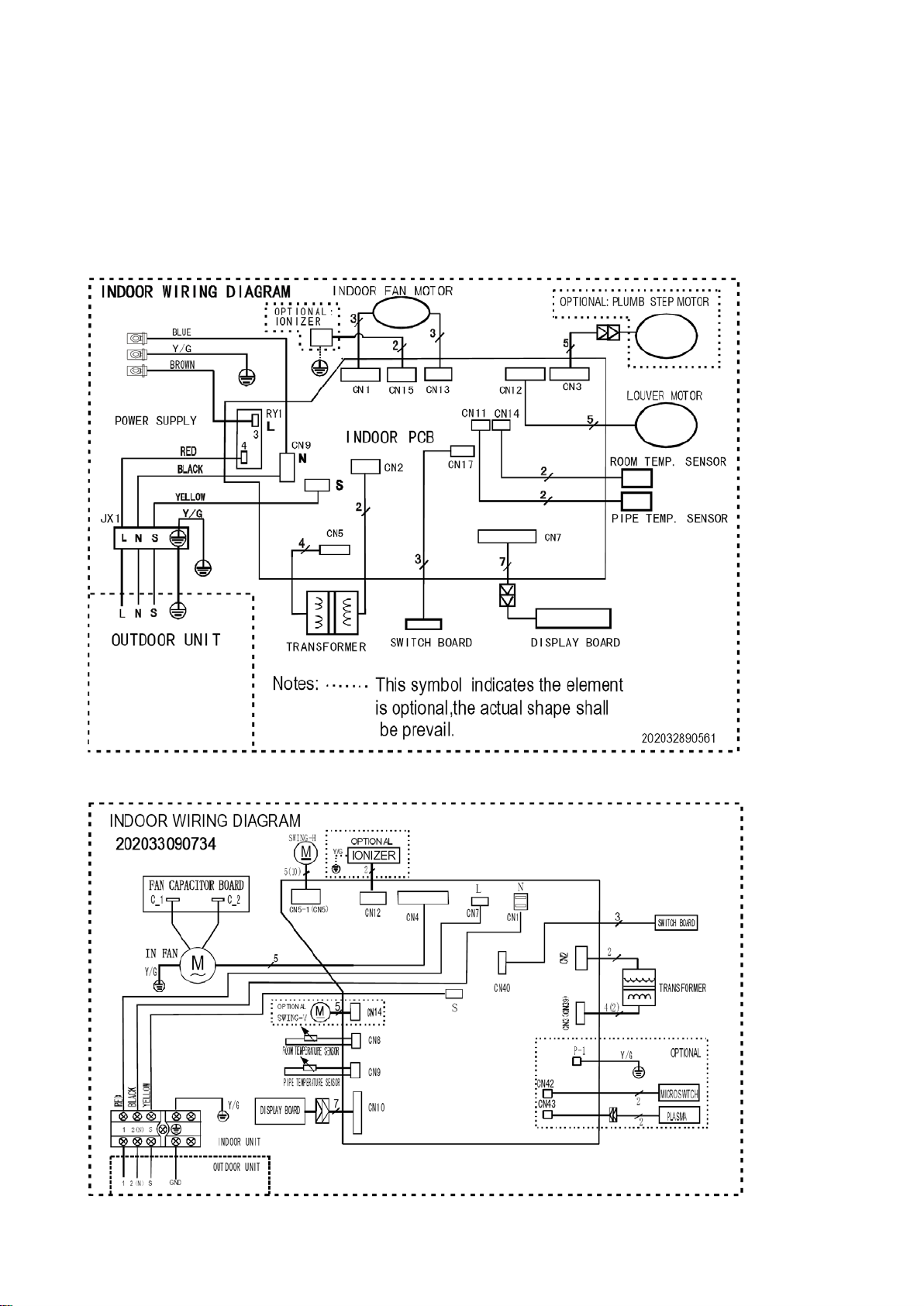
5. Wiring Diagram
5.1 Indoor
MS9V-18HRDN1-QC2(B)
MS9V-24HRDN1-QC2
Page 15

13
5.2 Outdoor Unit
MOC2-18HDN1-QC2
MOF-24HDN1-QC2W
Page 16

14
mm
inch
N·cm
N·cm
6. Installation details
6.1 Wrench torque sheet for installation
Outside diameter Torque Additional tightening torque
Ф6.35 1/4
Ф9.53 3/8
Ф12.7 1/2
Ф16 5/8
1500
(153kgf.cm)
2500
(255kgf.cm)
3500
(357kgf.cm)
4500
(459kgf.cm)
1600
(163kgf.cm)
2600
(265kgf.cm)
3600
(367kgf.cm)
4700
(479kgf.cm)
6.2 Connecting the cable s
The power cord of connect shoul d be s elected according to the following spec ifications sheet.
Grade
Unit
mm2
18K 24K
2.5 2.5
6.3 Pipe length and the elevation
Pipe size Standard
Capacity
length
Btu/h
Gas Liquid
(m)
18K 1/2’’(Ф12.7) 1/4"(Ф6.4) 5 10 25 20
24K 5/8’’(Ф16) 3/8’’(Ф9.53) 5 10 25 40
Max.
Elevation
B (m)
Max.
Length
A (m)
Additional
refrigerant
(g/m)
Page 17

15
(Indoor unit)
(Liquid side)
(Gas side)
Vacuum
pump
Vacuum
pump
adaptor
Lo Hi
Handle Hi
Two-way valve
Close
Manifold valve
Compound meter
Pressure
gauge
-76cmHg
Handle Lo
Charge hose
Charge hose
(Outdoor unit)
Close
Three-way valve
Caution:
Capacity is base on standard length and maximum allow ance length is base of reliability.
Oil trap should be insta ll ed per 5-7 meters.
6.4 Air purging with vacuum pump
Air and moisture in the refrigerant system have undesirable effects as below:
● Pressure in the system rises.
● Operating current rises.
● Cooling or heating efficiency drops.
● Moisture in the refrigerant circuit may freeze and block capillary tubing.
● Water may lead to corrosion of parts in the refrigerant system.
Therefore, the indoor units and the pipes between indoor and outdoor units must be leak tested and evacuated to
remove gas and moisture from the system.
Air purging with vacuum pump
Page 18

16
1. Completely tighten the flare nuts of the indoor and outdoor units, connect the manifold valve charge.
2. Connect the charge hose connection to the vacuum pump.
3. Fully open the handle Lo of the manifold valve.
4. Operate the vacuum pump to evacuate. After starting evacuation, slightly loose the flare nut of the Lo valve
on the gas pipe side and check the air is entering. (Operation noise of the vacuum pump changes and a
compound meter indicates 0 stead of minutes)
5. After the evacuation is complete, fully close the handle Lo valve of the manifold valve and stop the
operation of the vacuum pump. Make evacuation for 15 minutes or more and check the compound meter
indicates -76cmHg.
6. Turn the stem of the Hi valve about 45°counterclockwise for 6 or 7seconds after the gas coming out, then
tighten the flare nut again. Make sure the pressure display in the pressure indicator is a little higher than the
atmosphere pressure.
7. Remove the charge hose from the Lo pressure charge hose.
8. Fully open the Hi and Lo packed valve.
9. Securely tighten the cap of the packed valve.
Gas leak check
Soap water method
Apply soap water or a liquid neutral detergent on the indoor unit connections or outdoor unit connections by
a soft brush to check for leakage of the connecting points of the piping. If bubbles come out, the pipes have
leakage.
6.5 Pumping down (Re-installation)
Page 19

17
Procedure
1. Confirm that both the 2-way and 3-way valves are set to the opened posit io n.
Remove the valve stem caps and confirm that the valve stems are i n the opened position.
Be sure to use a hexagonal wr ench t o operate the valve stems.
2. Operate the unit for 10 to 15 minut es .
3. Stop operation and wait for 3 min utes, the n conne ct the char ge set t o the serv ice port o f the 3-way
valve.
Connect the charge hose w ith the push pin to the gas service port.
5. Air pur ging of the charge hose.
Open the low-pressure v al ve on the charge set slightly to purge air from the charge hose.
6. Set the 2-way valve to the close position.
7. Operate the air conditio ner at t he cooling cycle and stop it when the gauge indic at es 0. 1MPa.
8. Immediately set the 3-way valve to the closed position.
Do this quickly so that the gauge ends up indicating 0.3 to 0.5Mpa.
Disconnect the charge set , and amount the 2-way and 3-way valv e’s stem nuts and service port
caps.
Use a torque wrench to tig ht en t he ser vice port cap.
Be sure to check for gas leakage.
Page 20

18
6.6 Re-air purging (Re-installation)
Procedure:
1. Confirm that both the 2-way and 3-way valves are set to the closed position.
2. Connect the charge set and a c har ging cylinder to the service port of the 3-way valve.
Leave the valve on the charging cylinder closed.
3. Air purging.
Open the valves on the ch arging cyli nder and the charge set . Purge t he air by l oosening t he flare nu t
on the 2-way valve approx i mately 45’ for 3 seconds t hen closing it for 1 minute; repeat 3 times.
After purging the air, use a torque wrench to tig ht en the flare nut to on the 2-way valve.
4. Check the gas leakage.
Check the flare connections for gas leakage.
5. Discharge the refrigerant.
Close the valve on the charging cylinder and discharge the refrigerant unt il the gauge indicates 0.3
to 0.5 Mpa.
6. Disconnect the charge set and t he c harging cylinder, and set the 2-way and 3-way v alves to the
open position.
Page 21

19
Be sure to use a hexagonal wr ench t o operate the valve stems.
7. Mount the valve stems nuts and the service port cap.
Be sure to use a torque wrench to t ight en the service port cap to a torque 18N.m.
Be sure to check the gas leaka ge.
6.7 Balance refrigerant of the 2-way, 3-wa y valves
Procedure:
1. Confirm that both the 2-way and 3-way valves are set to the open position.
2. Connect the charge set to the 3-way valve’s service port.
Leave the valve on the charge set closed.
Connect the charge hose with the push pin to the service port.
3. Open the valves (Low side) on the charge set and discharge the refrigerant until the gauge
indicates 0.05 to 0.1Mpa.
If there is no air in the refrigeration cycle [the pressure when the air conditioner is not running is higher than
0.1Mpa, discharge the refrigerant until the gauge indicates 0.05 to 0.1 Mpa. If this is the case, it will not be
necessary to apply an evacuation.
Discharge the refrigeration gradually; if it is discharged too suddenly, the refrigeration oil sill be discharged.
Page 22

20
6.8 Evacuation
Procedure:
1. Connect the vacuum pump to the charge s et’s centre hose.
2. Evacuation for approxi mately one hour.
Confirm that the gauge ne edle has moved tow ard -0. 1 Mpa (-7 6 cm Hg) [vacuu m of 4 mmH g or less].
3. Close the valve (Low side) on t he c harge set, turn off the vacuum pu mp, and confirm that the
gauge needle
does not move (approxi m at ely 5 m inut es after turning off the v acuum pump).
4. Disconnect the charge hose from the vacuum pump.
V acuum pump oil, if the vacuum pump o il b ecomes dirty or depleted, replenish as needle.
Page 23

21
6.9 Gas charging
Procedure:
1. Connect the charge hose to the charging cylinder.
Connect the charge hose which you disconnected from the vacuum pump to the valve at the
bottom of the cylinder. If the refrigerant is R410A, make the cylinder botto m up t o ens ure l iquid c harg e.
2. Purge the air from the charge h ose.
Open the valve at the bottom of the cylinder and pr ess t he chec k valve on the charge set to purge
the air (be careful of the liqui d r efrigerant).
3. Open the valves (Low side) on the charge set and charge the system with l i qui d r efrigerant.
If the system cannot be ch arge with t he speci fied amount of refrig erant, i f can be charg ed with a little
at a time (approximately 150g each time0 while operating the air conditi oner in the cooling cycle;
however, one time is not suffic ient, wait appro xim ate ly 1 m inut e and t he n repe at the proc edur e.(pu mpin g
down-pin).
4. Immediately disconne ct the charge hose from the 3-way valve’s service port.
Stopping partway will allow the refriger ant to be discharged.
If the system has been charged with liquid refrigerant while operating the air conditioner, turn off
the air conditioner before disconnecting the hose.
5. Mounted the valve stem ca ps and the service port
Use torque wrench to tight en the service port cap to a torque of 18N.m.
Be sure to check for gas leakage.
Page 24

22
7. Operation characteristics
Mode
Cooling operation Heating operation
Temperature
Room temperature
Outdoor te mperature
CAUTION:
1. If air conditioner is used outs ide o f the above conditions, certain safety protection feat ur es may
come into operation and cause the unit to function abnormally.
2. Room relative humid ity less tha n 80%. If the air c onditioner oper ates in exce ss of this figure, the
surface of the air conditioner may attract condensation. Please sets the vertical air flow louver to its
maximum angle (vertica lly to the floor), and set HIGH fan mode.
3. Optimum performance will be achieved within this operating temperature.
(-15℃~50℃:For the mode ls with
low temperature cooling system)
≥17℃ ≤ 30℃
0℃~50℃
-15℃~34℃ 0℃~ 50℃
Drying
operation
﹥10℃
Page 25

23
Flash at 0.5Hz when the unit is standby. Illuminate when the unit is turned on.
Timer indicator
TEMPERATURE indicator
8. Electronic function
8.1 Abb rev iation
T1: Indoor ambient temper at ur e
T2: Pipe temperature o f indoor heat exchanger
T3: Pipe temperature o f outdoor heat exchanger
T4: Outdoor ambient t emp er ature
T5: Discharge temperature
8.2 Display function
8.2.1 Icon explanation on indoor display board.
Run indicat or
Auto indicator
This indicator illuminates when the air conditioner is in AUTO operation.
This indicator illuminates when TIMER is set ON/OFF.
Defrost Indicator
This indicator illuminates when the air conditioner starts defrosting automatically or when the
8.2.2 LED display control function.
warm air control feature is activated in heating mode
Usually it displays the temperature settings. When change the setting temperature, this indicator
begins to flash, and stops 20 seconds later. It displays the room temperature when the air
conditioner is in FAN only operation, and the range of that is 0~50℃. It will also display the error
codes when malfunction or protection happen.
TURBO operation display (Control by rem ote controller)
Illuminated when select TURBO function in cooling operation or in heating operation.
Pressing “LED display” button on remote controller will turn off all displays on indoor unit, while pressing
Page 26

24
once again, all displays will resume.
8.3 Main Protec tion
8.3.1 Three Minutes Delay at restart for compressor .
---- 1 minutes delay for the 1
st
time start-up and 3 minutes delay for others.
8.3.2 Te mp erature protection of compressor top.
---- Top temp. protector cut off for 30s and restart the compressor with 3 minutes delay.
8.3.3 T em per ature prot ection of compressor di scharge.
When the compressor discharge temperature is getting higher, the running frequency will be
limited as below rules:
----Compressor discharge temp. T5>115 ℃ for 5s;compressor stop.
---- 108<T5<115 ℃, decrease the frequency to the lower level every 3 minutes.
---90<T5<105 ℃, keep running as the current frequency.
----T5<90 ℃, no li m it for frequency or restart compressor
8.3.4 Fan Speed is out of control.
---- When Indoor Fan Speed is too low (lower than 300RPM for 50 seconds), the unit stops and LED
displays failure
8.3.5 Inverter module Pr ot ect i on.
----Inverter module Protect ion it se l f has a protect ion fun ction against c urrent, volt ag e and te mperat ure.
If these protections happened, the corresponding code will display on indoor unit LED. Th e unit will
stop operation if the protection occurred, and recover 3min delay a fter the protection disappeared.
8.3.6 Indoor fan delayed open functio n
----When system starts up, the louver will be active immediat ely and t he indoor fan will open after 10s.
----If the system runs at heating m ode, the anti-cold wind function has priority.
8.3.7 Compressor preheating functions.
----Preheating permitting c ondition:
If the main relay closed, T4<3 ℃ and the machine is first power on, or T4<3 ℃ and compressor has
stopped for over 3 hours, t he compressor heating cable will work.
----Preheating mode:
A weak current flows through the coil of compressor from the wiring terminal of compressor, then the
compressor is heated without operation.
Page 27

25
or user turns on the ma
----Preheating release conditio n:
If T4>5 ℃
---- Crankcase Heater
It starts when T4<5 ℃ and stops when T4>15℃
8.4 Operation Modes and Functions
8.4.1 Fan only mode.
(1) Outdoor fan and compressor stop.
(2) Temperature setting function is disabled, and no setting temperatur e is display.
(3) Indoor fan can be set to high/med/l ow / auto.
(4) The louver operat es same as in cooling mode.
(5) The action of auto fan in fan-only mode is the same as auto fan in cooling mode with 24 ℃ s ettin g
temperature.
8.4.2 Cooling Mode
8.4.2.1 Compre ssor running rules:
The operation frequency of compressor after starting submits to following rule.
Page 28

26
Temp.zone
A B C D E F G
Frequency
F8
F8
F7
F6
F5
F3
F1
After A/C starts up, the co mpressor will run at the Fmax frequency for 7 minutes. During the 7
minutes, frequency limitation is active.
7 minutes later, compressor running frequ ency will be controlled as below:
While
Note:
When T1-Ts keep in the same temperature zone for 3 minutes, the compressor will run as the below
rules:
A~E: Increase the frequency to the higher level until to F8.
Page 29

27
F: Keep the current frequency.
G: Decrease the frequenc y to the lower level until to F1.
H: Run at F1 for 1h (if T1-Ts<-2 ℃, com pressor will stop)
Meanwhile, the compressor running frequency is limited by t he c ur rent.
TYPE I1COOL I2COOL I3COOL
18K 4.5 5.5 6.5
24K 11 12 13
If the current increased more than I2COOL, the frequency will decrease automatically, if the current
raise to over I3COOL the compressor will stop and restart 3min later.
During the frequency decreasing, if the current deceased to between I1COOL and I2COOL, the
frequency will hold. If the frequency not changed for 3min, the frequ ency will increas e to a higher level,
and it can increase twice at most.
If the current deceased to lower t han I1COOL, the frequency limit will be invalid
8.4.2.2 Out door fan running rules:
Outdoor fan and compressor start up at the same time, outdoor fan stop 30s delay after the
compressor stopped.
The outdoor fan have two speeds, it’s controlled by T4 as following rules:
Page 30

28
8.4.2.3 Indoor fa n running rules
In cooling mode, indoor fan runs all the time and the s peed can be selected as high, medium, low and
auto.
Auto fan in cooling mode acts as follow:
8.4.2.4 Condenser high temperature T3 protection.
When 55℃<T3<60℃, the compressor frequency will decrease to the lower level every 3 min until to
F1 and then run at F1.IF T3<54℃, the compressor will keep runn ing at the current frequency.
When T3<52℃, the compr essor w ill not limit the frequency again and resume to the former frequency.
When T3>60℃ for 5 seconds, the compressor will stop and restart until T3<52℃.
8.4.2.5 Evaporator low temperature T2 protection.
When T2<0 ℃, the compressor will stop and restart when T2>=5 ℃.
When 0 ℃≤T2<4 ℃, the compressor frequency will decrease to the lower level every minute until stop
the compressor.
When 4 ℃≤ T2≤7℃, the compressor will keep the current frequency.
When T2>7 ℃, the compressor frequency will not be limited.
8.4.3 Heating Mode
8.4.3.1 Compre ssor running rules:
The operation frequency of co mpressor after starting submits to following rule.
Page 31

29
Temp. zone
A B C D E F G H Frequency
F10
F9
F8
F7
F5
F3
F1
F0
After AC starts up, the compressor will run at the Fmax frequency for 7 minutes according to outdoor
ambient temp. During the 7 m inutes, frequency limitation is activ e.
7 minutes later, compressor running frequency will be controlled as below:
While
ΔT=0 ℃ a s d e fa u l t.
Page 32

30
Note:
When T1-Ts keep in the same temperature zone for 3 minutes, the compressor will run as the below
rules:
A~E: Increase the frequency to the higher level until to F10.
F: Keep the current frequency.
G: Decrease the frequenc y to the lower level until to F1.
H: Run at F1 for 1h.(if T1-Ts-ΔT >6 ℃, com pressor will stop )
Meanwhile, the compressor running frequency is limited by t he c ur rent.
TYPE I1HEAT I2HEAT I3HEAT
18K 5 6 7
24K 11 12 13
If the current increased more than I2HEAT, the frequency will decrease automatically, if the current
raise to over I3HEAT, the compressor will stop and restart 3min later.
During the frequency decreasing, if the current deceased to between I1HEAT and I2HEAT, the
frequency will hold. If the frequency not changed for 3min, the frequency will increase to a higher level,
and it can increase twice at most.
If the current deceased to lower t han I1HEAT, the frequency limit w i ll b e invalid.
8.4.3.2 Out door fan running rules:
Outdoor fan and compressor start up at the same time, outdoor fan stop 30s delay after t he
compressor stopped.
The outdoor fan have two speeds, it’s controlled by T4 as following rules:
Page 33

31
8.4.3.3 Indoor fa n running rules:
The speed can be selected as hi gh, m edium, low and auto, the anti-cold-wind function has the priory.
If reached the set temperature, the indoor fan transfers to lowest speed, the anti-cold wind function
has the priory.
If mode transferred or compressor restarted, indoor fan works with setti ng f an speed.
Anti-cold-wind function contr ol principl e :
For the18K unit
For the 24K unit
Page 34

32
Auto fan action i n heating mode.
8.4.3.4 Defrosting mode:
Conditions of defrosting:
Condition 1: If T4>0 ℃,
When the units are running, if any one of the following conditions is satisfied, the unit starts defrosting:
① If the accumulated time of the unit working within T3<3 ℃reached 40 minutes and T3 keeps lower
than -6 ℃ over 3 minutes.
② If the accumulated time of the unit working within T3<3 ℃reached 80 minutes and T3 keeps lower
than -4 ℃ over 3 minutes.
Condition 2: If T4<0 ℃,
If satisfied any item of the condit io n 1 and the T2 temperature has decr eased 5℃, starts defrosting.
Note: T2 is the maximum value of the evaporator temperature during the anti-cold wind function. It’s
recorded by the system a ut om at ically.
Condition 3:
No matter what value T4 is, if the accumulated time of the unit working within T3<3 ℃reached 120
minutes and T3 kee ps lower than -2℃ over 3 minutes, st ar ts defrosting.
Condition of ending defros ting:
If any one of following items is sat isfied, de frostin g will stop and the mach ine will turn to nor mal heatin g
mode.
① For the 18K unit : T3 >12℃; For the 24K unit:: T3 >15℃;
② T3>8 ℃ and remains for 80 seconds.
③ The defrosting time lasts 10min.
Defrosting action:
Page 35

33
For 18K units
For 24K units
Model FD FD1
MS9V-24HRDN1-QC2W+MOF-24HDN1-QC2W 90 100
8.4.3.5 High evaporator coi l t em p. T2 protection:
(1) T2> TEH2, compressor running freque ncy decreases t o the lower lev el every 20s. If t he frequency
decreased to F2 and the T2 s till o v er
TEH2 for 3 minutes, the compressor w ill stop. If T2 deceased to
Page 36

34
lower than 48 ℃, or 48 ℃<T2< TEH2 last for 6 minutes, release the frequency limit control.
(2) If T2>60℃, stop the compressor and rest arts until T2<48℃.
Note:
TEH2
8.4.4 Auto-mode
This mode can be chos en wit h re mote cont ro ller and t he settin g te mper ature can be cha nge d b etwee n
17~30 ℃.
In auto mode, the machine will choose co olin g, heat ing or fan-only mode according to ΔT (ΔT =T1-Ts).
ΔT=T1-Ts Running mode
ΔT>1 ℃
-1<ΔT ≤1℃ Fan-only
ΔT≤-1 ℃ Heating
Indoor fan will run at auto fan of the r elevant mode.
The louver operates sa me as in rel evant mode.
24K 55℃
Cooling
18K 53℃
If the machine switches mode between heating and cooling, the compressor will keep stopping for 15
minutes and then rechoos e mo de according to T1-Ts.
If the setting temperature is mo dified, the machine will rechoose running function.
8.4.5 Dehumidify mode
8.4.5.1 Indoor fan speed is fixed at breeze and can’t be changed. The louver angle is the same as in
cooling mode.
8.4.5.2 Compressor running rules
8.4.5.3 Room over low temperature protectio n
Page 37

35
, compresso
In drying mode, if room te mperature is lower t han 10 ℃
temperature exceeds 12 ℃.
8.4.5.4 Evaporator anti-freezing protection, condenser high temperature protection and outdoor unit
frequency limit are valid, and they are the same as that in cooling mo de.
8.4.5.5 The outdoor fan oper at es same as in cooling mode.
8.4.6 Forced operation function
8.4.6.1 Enter forced opera t ion f unct i on:
Pressing the touch button once, the machi ne w il l transfer into forced auto mode, if pressing the button
once again, the machine will tur n into forc ed co olin g mode, t he th ird pre ssi ng w ill stop t he u nit, and t he
forth pressing is the start of the cycle of forced auto mode, forced cooling mode and stop. Refer the
following chart:
8.4.6.2 In forced operation mod e, al l general protections and remote contr ol are available.
8.4.6.3 Operation rules:
Forced cooling mode:
The compressor runs at F2 frequency and indoor fan runs as breez e. After running for 30 minutes. the
machine will turn to auto mode as 24℃ setting temperature.
Forced auto mode:
The action of forced auto mo de is the same as normal auto mode with 24 ℃ se ttin g tem pe ra tu
8.4.7 Timer function
8.4.7.1 Timing range is 24 hours, and the minimum resolution is 15 minutes.
8.4.7.2 Timer on. After turning off, the machine will turn on automatically when reaching the setting
time.
8.4.7.3 Timer off. After turning on, the machine will turn off automatically when reaching the setting
time.
8.4.7.4 Timer on/off. After turning off, the machine will turn on automatically when reaching the
setting “on” time, and then t ur n off automatically when reaching the setting “off” time.
8.4.7.5 Timer off/on. After turning on, the machine will turn off automatically when reaching the
Page 38

36
) every one
) every one
setting “off” time, an d t hen turn on automatically when reaching the s etting “on” time.
8.4.7.6 The setting t i me is relative time.
8.4.7.7 The toleranc e of t i mer is 1 minute per hour.
8.4.8 Sleep func t ion mode
8.4.8.1 Operation time in slee p mode is 7 hours. A fter 7 hours the AC quits this mode and turns of f.
8.4.8.2. Operation proce ss in sleep mode is as follow:
After pressing ECONO M IC or SLEEP button on cont roll er, the machine will turn into sleep mode.
When cooling, the setting temperature rises 1℃ (be lower than 30 ℃
setting temperature sto ps rising and indoor fan is fixed as low speed.
When heating, the setting temperature decreases 1 ℃ (be higher than 17 ℃
later the setting temperature stops rising and indoor fan is fixed as low speed.(Anti-cold wind function
has the priority)
8.4.8.3 Timer setting is available
8.4.8.4 When user uses timer off function in sleep mode(or sleep function in timer off mode), if the
timing is less than 7 hours, sleep function will be cancelled wh en reaching t he sett ing time. If the t iming
is more than 7 hours, the machine will not stop until reaches the setting time in sleep mode.
8.4.9 Auto-Restart function
The indoor unit is equipped with auto-restart function, which is carried out through an auto-restart
module. In case of a sudden power failure, the module memorizes the setting conditions before the
power failure. The unit will resume the previous operation setting (not including Swing function)
automatically after 3 minutes when power returns.
If the memorization condition is forced cooling mode, the unit will run in cooling mode for 30 minutes
and turn to auto mode as 24 ℃ se ttin g tem p.
If A/C is off before power off and AC is required to start up now, the compressor will have 1 minutes
delay when power on. Other conditions, the compressor will have 3 minutes delay when restarts.
8.4.10 Ionizer (Clean Air) function (optional)
8.4.10.1 Clean Air function is available only when the aircon is on, and it’s controlled through remote
controller.
8.4.10.2 After the Aircon being turned on, the Clean Air function is switched on when the aircon
receives FRESH CODE at first time, and ionizer is switched off when the aircon receives the CODE
again. It’s a circle.
Page 39

37
8.4.10.3 After starting the Clean Air function, the ionizer can work only when the indoor fan motor is
running. If the indoor fan motor is off, the ionizer also stops working, even though the Clean Air
function is available.
8.4.10.4 Switching the runnin g mod e wi ll not st op th e ioniz er. When turning off the aircon, the ionizer is
also turned off.
8.4.11 Automatic panel function (for 18K unit optional)
8.4.11.1 Th e aut omatic panel is forced to turn to the closing direction at an angle of 60°when the unit
is getting through the power, and this action is not affected by any signal from r emote controller.
8.4.11.2 When the unit is turned on, the panel is opened automatically at an angle of 60°, then the
horizontal louver will be opened.
8.4.11.3 When the unit is turned off, the panel is closed automatically at an angle of 60°, then the
horizontal louver will be closed.
8.4.11.4 If the panel needs moving when the horizontal louver is in action, the unit will stop the
horizontal louver and then carry out the action of the panel. After ending the action of the panel, the
horizontal louver will continue its action.
9. Troubleshooting
Safety
Because of t capacitor s in PCB and relative circuit in outdoor unit, even shut down the power supply.
Electricity power still are kept in cap acitors, do not fo rget to dischar ge the ele ctricity pow er in capa citor.
Electrolytic Capacitors
(HIGH VOLTAGE! CAUTION!)
Page 40

38
Bulb (25-40W)
9.1 Indoor Unit Error Display
Display LED STATUS
E0 EEPROM parameter error
E1 Indoor / outdoor units communication protect ion
E2 Zero-crossing signal error
E3 Indoor fan speed out of control
E5 Open or short circuit o f ou tdoor temperature sensor
E6 Open or short circuit o f room or evaporator temperature sensor
E7 Outdoor fan speed out of control
P0 IBM malfunction or I G BT over-strong current protection
P1 Over voltage or too l ow voltage protection
P2 Temperature protection of compressor top.
P4 Inverter compressor dr ive error
Note: E4 & P3: Reserved function
Page 41

39
Replace indoor PCB
Shut off the power supply and turn on it 5s later
The problem comes out again
Is the EEPROM chip plugged in indoor PCB well?
NO
Correct the connection
Replace the main PCB of indoor unit
9.2 Diagnosis and Solution
9.2.1 E0(EEPROM parameter error) error diagnos is and solution
Page 42

40
NO
Reconnect and retest
Replace outdoor e-box.
No
Correct the connection.
Replace indoor PCB
and repower on. Is
the connection of L, N, S and GND good?
comparing with wiring plate. Is the
connection good?
The unit does not
9.2.2 E1(indoor / outdoor units communicati on protection) error diagnosis and solution
Turn off the power supply, after 1 minute, connect the power
supply, and turn on the unit with remote controller
The unit does not work normally.
Check the wiring between indoor and outdoor unit. Is
Yes
Is the LED4(red) bright and LED1(yellow)
blinking on outdoor PCB?
The power supply for outdoor PCB is fail.
Check the wiring on outdoor PCB
No
Yes
work normally.
Yes
Page 43

41
Turn off the power supply and turn on it
Is power supply and
Indoor PCB is defective.
Be sure the power supply is
good and correct the
connection
9.2.3 E2(zero-crossing signal error) diagnosis and solution
again 5 seconds later
connection of connectors
good?
NO
YES
Replace the indoor PCB.
Page 44

42
Is the indoor fan motor connector and
The unit does not work normally
Does it rotate freely?
NO
the below step.
YES
Replace the indoor PCB
YES
YES
Shut off the power supply and turn on it 5s later
YES
YES
Check the connections between the
sensors and the PCB. Are the
connections good?
9.2.4 E3 (indoor fan speed out of control) diagnos i s
Turn off the unit, rotate the cross fan.
connection good?
Check the voltage between the red and
black wires of motor power input .Is it in
range of AC90-160V?
NO
Disassemble the connection between fan
and motor, check if the bearing is normal.
If not, change the bearing. If yes, follow
Replace the fan motor
9.2.5 E5/E6(Open or short circuit of tempera ture sensor) diagn os i s and solution.
Replace the sensor and check if the
Replace outdoor PCB
errors happen again?
Page 45

43
Is the power supply good?
Make sure the power supply is normal.
YES
YES
Fastening the IPM to the radiator
Check whether the connections between
Check whether the IPM is fixed to radiator
Replace the IPM
The unit does not work normally
Replace the compressor
9.2.6 P0 (IGBT over-strong current pr ot ection) diagnosis a nd solution.
outdoor PCB and IPM are good?
NO
tightly or if the fastening reliable
9.2.7 P1 (over voltage or too low voltage protecti on) diagnosis and solution.
Replace the outdoor e-box.
NO
Page 46

44
Replace inverter compressor.
Reconnect and retry
NO
right? The voltage range
YES
after gas charging?
Replace the outdoor PCB.
Reconnect and
retest.
YES
Is protector normal?
NO
Refrigerant is blocked(Such as capillary or
welded points of the pipes.
Is refrigerant circulation
Replace the protector.
9.2.8 P2 (temperat ur e protection of compre ssor top) diagnosis and solution.
Does compressor operate?
YES
volume normal?
NO,
Charge refrigerant
Is abnormality the same
Is the connection good?
NO
NO
9.2.9 P4 (inverter compre ssor drive error) diag nosis and solution.
Is the connection of compressor good? Is the
wiring sequence
proper?
YES
NO
Replace the outdoor PCB
 Loading...