

Midea MPPD-12CRN1-BH9, MPPD-14CRN1-BH9, MPPD-14HRN1-BH9, MPPD-12ER-NB4, PD Service Manual
...Page 1
R
R
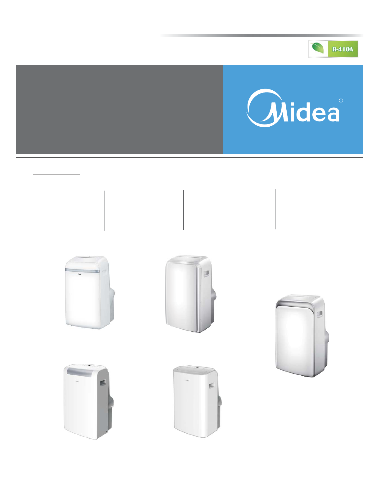
North America Air Conditioner
PORTABLE
SERVICE MANUAL
PD SERIES
Models:
MPPD-12CRN1-BH9
MPPD-14CRN1-BH9
MPPD-12HRN1-BH9
MPPD-14HRN1-BH9
PD
(standard panel)
PD1 PD3
PDA
PDB(panel used for small body)
MYPD-12CRN1-QB6
Cooling-only
Heat pump
Electronic heater
MPPD-12ER-NB4
Dual-hose
MPPD-12CRN1-BI0(small body)
Page 2
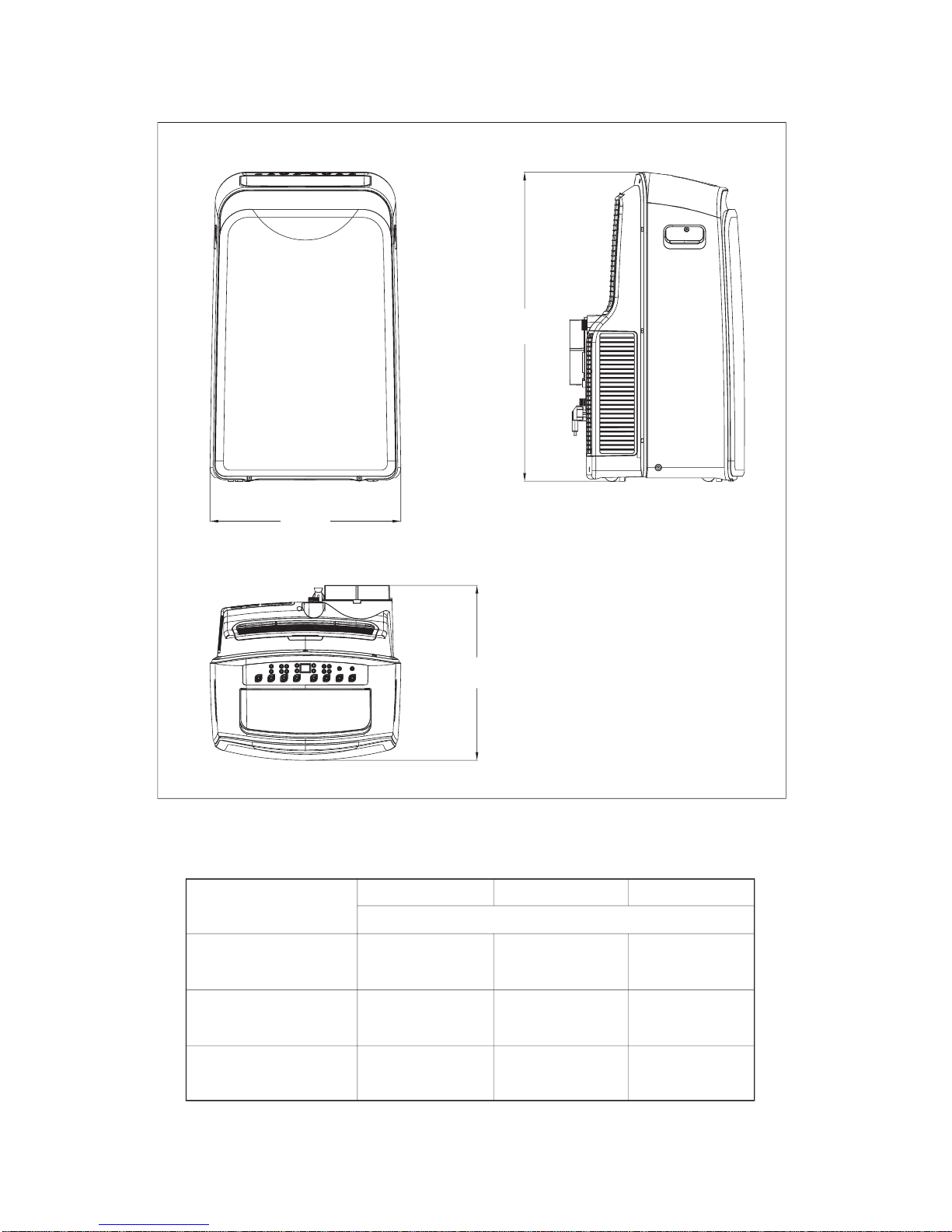
1. DIMENSION
W
H
D
Unit Dimension
Single-hose
(small body)
Single-hose
Double-hose
WHD
mm(inch)
454(17.9)
467(18.4)
467(18.4)
700(27.6)
765(30.1)
765(30.1)
365(14.4)
397(15.6)
478(18.8)
Page 3

2. OPERATION MODES AND INSTRUCTIONS
POWER BUTTON
Power switch on/off.
SLEEP/ECO BUTTON
Used to initiate the SLEEP/ECO
operation.
NOTE: On some models SLEEP
button is instead of ECO button.
FAN/ION BUTTON
(ION is optional)
Control the fan speed. Press to select the
fan speed in four steps-LOW, MED, HI
and AUTO.The fan speed indicator light
illuminates under different fan settings
except AUTO speed. When select AUTO
fan speed, all the fan indicator lights turn
dark.
NOTE: Press this button for 3 seconds to
initiate ION feature.The ion generator is
energized and will help to remove pollen
and impur ities from the air, and trap them
in the filter. Press it for 3 seconds again to
stop the ION feature.
UP(+) AND DOWN(-) BUTTON
Used to adjust (increasing/
decreasing) temperature settings
(2 ℉/1℃increments) in a range of
62 ℉(17℃) to 88℉(30℃) or the
TIMER setting in a range of 0~24hrs.
NOTE:
The control is capable of displaying
temperature in degrees Fahrenheit or
degrees Celsius. To convert from one
to the other, press and hold the Up
and Down buttons at the same time,
for 3 seconds.
MODE SELECT BUTTON
Selects the appropriate operating mode.
Each time you press the button, a mode
is selected in a sequence that goes from
AUTO, COOL, DRY, FAN and HEAT
(cooling only models without).
The mode indicator light illuminates
under the different mode settings..
2.1 OPERATION MODES
1
2
3
4
5
1
1
2344567
8
9
Optional
Page 4

TIMER BUTTON
Used to initiate the AUTO ON start
time and AUTO OFF stop time program,
in conjuction with the
(+)
&
(-)
buttons.
The timer on/off indicator light
illuminates under the timer on/off
settings.
SWING BUTTON
(Applicable to the models with auto
swing feature only)
Used to initiate the Auto swing feature.
When the operation is ON, press the
SWING button can stop the louver at
the desired angle.
LED DISPLAY
Shows the set temperature in " ℃" or
" ℉" and the Auto-timer settings.
While on DRY and FAN modes, it shows
the room temperature.
FOLLOW ME/TEMP SENSING
(OPTIONAL)
NOTE:This feature can be activated
from the remote control ONLY.
The remote control servesas a remote
thermostat allowing for the precise
temperature control at its location.
To activate the Follow Me/Temp
Sensing feature, point the remote
control towards the unit and press
the Follow Me/Temp Sensing button.
The remote display is actual
temperature at its location. The remote
control will send this signal to the air
conditioner every 3 minutes interval
until press the Follow Me/Temp
Sensing button again.If the unit does
not receive the Follow Me/Temp
Sensing signal during any 7 minutes
interval, the unit will beep to indicate
the Follow Me/Temp Sensing mode
has ended
6
7
8
9
2.2 OPERATION INSTRUCTIONS
COOL OPERATION
Press the "MODE" button until the
"COOL" indicator light comes on.
Press the ADJUST buttons "+" or " - "
to select your desired room temperature.
The temperature can be set within a
range of 62℉-88℉/17℃-30℃.
Press the "FAN SPEED" button to
choose the fan speed.
FAN OPERATION
Press the "MODE" button until the
"FAN " indicator light comes on.
Press the "FAN SPEED" button to
choose the fan speed.
The temperaturecannot be adjusted
Do not put the duct to window.
Page 5

HEAT OPERATION
(cooling only models without)
Press the "MODE" button until the
"HEAT" indicator light comes on.
Press the ADJUST buttons "+" or " - "
to select your desired room temperature.
The temperature can be set within a
range of 62℉-88℉/17℃-30℃.
Press the "FAN SPEED" button to
choose the fan speed. For some models,
the fan speed can not be adjusted under
HEAT mode.
Press the "MODE" button until the
"DRY" indicator light comes on.
Under this mode, you cannot select a fan
speed or adjust the temperature. The fan
motor operates at LOW speed.
Keep windows and doors closed for the
best dehumidifying effect.
Do not put the duct to window.
AUTO OPERATION
When you set the air conditioner in
AUTO mode, it will automatically select
cooling, heating(cooling only models
without), or fan only operation
depending on what temperature you
have selected.
and the room temperature.
The air conditioner will control room
temperature automatically round the
temperature point set by you.
Under AUTO mode, you can not select
the fan speed
TIMER OPERATION
When the unit is on, press the Timer
button will initiate the Auto-off stop
program, the TIMER OFF indicator
light illuminates. Press the UP or
down button to select the desired
time. Press the TIMER button again
within 5 seconds, the Auto-on start
program is initiated. And the
TIMER ON indicator light
illuminates. Press the up or down
button to select the desired Auto-on
start time.
When the unit is off, press the Timer
button to initiate the Auto-on start
program, press it again within five
seconds will initiate the Auto-off
stop program.
Press or hold the UP or DOWN
button to change the Auto time by
0.5 hour increments, up to 10 hours,
then at 1 hour increments up to 24
hours. The control will count down
the time remaining until start.
The system will automatically revert
back to display the previous temper ature setting if there is no operation
in a five seconds period.
Turning the unit ON or OFF at any
time or adjusting the timer setting
to 0.0 will cancel the Auto Start/
Stop timer program.
When the malfunction (E1,E2,E3
or E4) occurs, the Auto Start/Stop
timed program will also be cancelled.
Page 6

3.
ELECTRONIC FUNCTION
3.1 Abbreviation
T1: Indoor room temperature.
T2: Temperature of evaporator.
T3: Temperature of condenser.
TS: The setting temperature.
S1: Water level swicth
3.2 Main Protection
3.2.1 The compressor functions protection with a delay of three minutes.
Compressor will restart with a delay of three minutes once it stops
operation.But it is four minutes delay for Heat pump model’s restarting.
3.2.2 Sensor protection at open or short circuit.
A/D ≤2 Ω, Sensor protection at open circuit;
A/D≥253Ω, Sensor protection at short circuit.
(Table A in next page show you the relation between temperature
and resistance of sensor.)
3.2.3 Auto defrosting at cooling mode or drying mode.
At cooling or drying mode,when T2 ≤2℃ for 3 minutes continuously,
it enters into Auto defrosting function with compressor turning off.
If water level is below S1,outdoor fan motor turns off with three minutes
delay. Auto defrosting function relieves when T2≥10℃ or T2 malfunction or
changing for other operation modes .
SLEEP OPERATION
Press this button, the selected temperature will increase(cooling) or
decrease(heating) by 2℉/1℃ 30 minutes.The temperature will then increase
(cooling) or decrease (heating) by another 2℉/1℃ after an additional 30
minutes. This new temperature will be maintained for 7 hours before it
returns .to the originally selected temperature. This ends the Sleep mode and
the unit will continue to operate as originally programmed.
NOTE: This feature is unavailabe under FAN or DRY mode.
Page 7

CHARACTERISTIC OF TEMPERATURE SENSOR
TABLE A:
Temp.
℉℉/℃℃
Resistance
KΩ
Temp.
℉℉/℃℃
Resistance
KΩ
Temp.
℉℉/℃℃
Resistance
KΩ
-
-
62.6/17
14.6181
111.2/44
4.3874
15.8/-9 58.7079
64.4/18
13.918
113/45
4.2126
17.6/-8 56.3694
66.2/19
13.2631
114.8/46
4.0459
19.4/-7 52.2438
68/20
12.6431
116.6/47
3.8867
21.2/-6 49.3161
69.8/21
12.0561
118.4/48
3.7348
23/-5 46.5725
71.6/22
11.5
120.2/49
3.5896
24.8/-4 44
73.4/23
10.9731
122/50
3.451
26.6/-3 41.5878
75.2/24
10.4736
123.8/51
3.3185
28.4/-2 39.8239
77/25
10
125.6/52
3.1918
30.2/-1 37.1988
78.8/26
9.5507
127.4/53
3.0707
32/0 35.2024
80.6/27
9.1245
129.2/54
2.959
33.8/1 33.3269
82.4/28
8.7198
131/55
2.8442
35.6/2 31.5635
84.2/29
8.3357
132.8/56
2.7382
37.4/3 29.9058
86/30
7.9708
134.6/57
2.6368
39.2/4 28.3459
87.8/31
7.6241
136.4/58
2.5397
41/5 26.8778
89.6/32
7.2946
138.2/59
2.4468
42.8/6 25.4954
91.4/33
6.9814
140/60
2.3577
44.6/7 24.1932
93.2/34
6.6835
141.8/61
2.2725
46.4/8 22.5662
95/35
6.4002
143.6/62
2.1907
48.2/9 21.8094
96.8/36
6.1306
145.4/63
2.1124
50/10 20.7184
98.6/37
5.8736
147.2/64
2.0373
51.8/11 19.6891
100.4/38
5.6296
149/65
1.9653
53.6/12 18.7177
102.2/39
5.3969
150.8/66
1.8963
55.4/13 17.8005
104/40
5.1752
152.6/67
1.83
57.2/14 16.9341
105.8/41
4.9639
154.4/68
1.7665
59/15 16.1156
107.6/42
4.7625
156.2/69
1.7055
60.8/16 15.3418
109.4/43
4.5705
-
-
Page 8

3. 3 Operation Modes and Functions
The compressor and outdoor fan are OFF at Fan-only mode
(except P1 protection).
The speed of indoor fan can be optionally chosen as High/Mid/Low.
The TS can’t be controlled because of the LED displaying as T1.
The ION/TIMER functions are valid at the fan-only mode.
3.3.2 Fan-only mode function requirement
3.3.3 Cooling mode function requirement
3.3.1 Auto mode function requirement
TS range is 62℉~88℉ (17℃~30℃).
When T1<TS-1, select the setting temperature of TS-1
for Heating operation’s temperature.
When TS+2≥T1≥TS-1,select the Fan-only mode.
When T1>TS+2, select the setting temperature(TS )
for Cooling operation’s temperature.
The indoor fan motor operates at Auto-fan mode with speed
uncontrolled and not changed.
The speed of indoor fan can be optionally selected as High/Mid/Low.
The outdoor fan will be turned on as soon as the unit being on cooling
mode.The operation of outdoor fan is according to the compare of
T1 and TS when the water level is below to switch 1.
If not, the outdoor fan doesn’t work.
The compressor operates as below:
(T1-Ts)
℃
+1
0
Compressor on
Operation conditon
Compressor off
a) If T1﹥TS+1℃, outdoor fan
operates. After 15 seconds,
compressor operates.
b) The compressor is on, if T1≤TS,
this compressor will stop. If
outdoor fan operates for 3 minutes
at least, it will stop for a delay for 5
seconds.
Page 9

When the unit is off, the compressor stops at first, and the indoor/outdoor
fan will stop for a delay of 5seconds. (If it operates at heating mode, the
outdoor fan will be off for a delay of 30 seconds).
The ION/TIMER functions are valid at the cooling mode.
3.3.4 Drying mode function requirement
At Drying mode, TS can’t be controlled by display panel,
and LED display as T1.
The unit operates at drying mode. If T1>55.4℉(13℃), outdoor fan turns on,
and then the compressor operates after 15 seconds later.
T1 ℃
15
13
Compressor on
Operation conditon
Compressor off
a) When T1<55.4℉(13℃),
compressor stops working.
And outdoor fan will stop for a
delay of 5 seconds.
b) When T1≥59
℉(15℃), outdoor
fan operates, and compressor
will restart operation after
15seconds.
The speed can’t be controlled at drying mode, and indoor fan motor operates
at low speed.
The ION/TIMER functions are valid at the drying mode.
3.3.5 Heating mode function requirement(for Electronic Heater)
TS range is 62℉~88℉ (17℃~30℃).
The speed of indoor fan can be optionally chosen as Auto/High/Mid/Low.
At heating mode, the heater will operate according to the difference between
T1 and TS. Electronic heater operates as below:
(T1-Ts)℃
+1
0
Heater on
Operation conditon
Heater off
a) When T1﹤TS, indoor fan
operates firstly, then heater
operates after 4 seconds.
b) If T1﹥TS+1℃, turn off heater.
Then turn off indoor fan motor
for a delay of 10 seconds..
Page 10

3.4.6 Heating mode function requirement(for Heat Pump)
The ION/TIMER functions are valid at the heating mode.
TS range is 62℉~88℉ ( 17℃~30℃).
T1≤TS+41
℉(5℃), compressor operates;
T1﹥TS+42.8
℉(6℃), compressor stops;
T1﹤41
℉(5℃), heat pump mode is invalid; Water pump,fan motor, compressor
and shaded pole motor stop operation;
T1≥42.8℉(6℃) , heat pump mode resume.
When four-way valve open(on non-defrost situation), shaded pole motor is always off.
When compressor operates, outdoor fan motor is at high speed.
When compressor stops, outdoor fan motor stops for a delay of 30seconds.
If unit changes for other operation modes, four-way valve closes for a delay of
2 minutes than compressor.
When compressor is on, T2
﹤86℉(30℃), fan motor stops;
When T2
≥86℉(30℃) or compressor deing on operation for 30 seconds, indoor fan
motor is on operation for 3 minutes at first, then according to the temperture T2 to
choose speed.
If T2
≥100.4℉(38℃), unit operates at setting speed.
When compressor stops, indoor fan motor also stops, the unit can be set at high/mid/
low/auto speed. Indoor fan motor will be off for a delay of 20 seconds becaues of
compressor being off by change of temperature or power off.
Water pump control:
a) At Heat pump mode, when LED displays as P1, or S1 disconnets continuously for 5
seconds, water pump starts to drain.
b) If S1 closes continuously over 5 seconds, it means that the water level of chassis is
below to S1. After it lasts working for 100 seconds, it will stop.
c) If unit changes for other operation mode or power off, water pump closes immidiately.
Defrosting function:
1. Defrosting condition: T3
≤35.6℉(2℃), and operation time is up to 40 minutes.
2. Defrosting action:
a) Compressor operates, four-way valve and indoor/outdoor fan are off.
b) When time is over 7 minutes or temperatrue is over 40℃,the outdoor fan is on and
continuosely working till the defrosting over.
3. Defrosting over: Defrosting time is up to 10 minutes; T3≥122℉(50℃)
4. Outdoor fan works, and compressor stops. After 35 seconds, four-way valve
opens, 3 seconds later, the compressor operates.
Page 11

It’s invalid for compressor’s delay operation protection when unit is at
defrosting function mode.
On defrosting process, if malfunction occur, or power off, or change for
non-heating mode, unit will esc defrosting function mode.
At Heat pump mode, if P1 occurs, compressor, indoor/outdoor fan stop
immidiately. Four-way valve keeps open.
The ION/TIMER functions are valid at Heat pump mode.
4. MALFUNCTION
4.1 Error codes and Solution.
E1---Room temperature sensor error.
E2---Evaporator temperature sensor error.
E3---Condenser temperature sensor error.
Causation:
a) Port of temperature sensor is loose.
b) Temperature sensor is bad.
c) Circuit component is bad.
Solution:
a) Check the connection between temperature sensor and adaptor
is ok, if not, please make sure the port plugs into the adaptor hard.
b) Restart the unit. If it can not resume. Please use another good
temperature sensor instead.
c) Restart the unit. If it also can not resume. Please replace the PCB.
E4---Display panel communication error.
Causation:
Communication failure for 2 minutes consecutive between indoor and
outdoor.
a) Wire port is loose.
b) Circuit component of display panel is bad.
Page 12

c) Circuit component of PCB is bad.
Solution:
a) Check the wire between display panel and PCB, make sure the
connection is ok.
b) Restart the unit. If it can not resume after 2 minutes, please
replace the display panel.
c) Restart the unit. If it can not resume after 2 minutes, please
replace the PCB.
4.2 Protection code and Solution.
P1---Water full protection.
Causation: Water in tank is full.
Solution:
Connect the drain hose and drain the collected water away.
4.3 Others malfunction.
Unit does not operate when pressing on/off button
Causation:
a) LED display as P1.
b) Room temperature is lower than TS (Cooling mode).
Solution:
a) Drain the water in the tank.
b) Reset the temperature.
Page 13

Not cool enough
Causation:
a) The windows or doors in the room are open.
b) There are heat sources inside the room.
c) Exhaust air duct is not connected or blocked.
d) TS is too high.
e) Air filter is blocked by dust.
Solution:
a) Make sure all the windows or doors are closed.
b) Remove the heat sources if possible.
c) Connect the duct and make sure it can function properly.
d) Decrease the TS.
e) Clean the air filter.
Noisy or vibration
Causation:
The ground is not level or not flat enough.
Solution:
Place the unit on a flat, level ground if possible.
Power shut off at Heating mode
Causation:
The automatic over heat protection function.
When the temperature at the air outlet exceed 158
℉/70℃,
the unit will stop.
Solution:
Restart the unit after it has cooled down.
Page 14
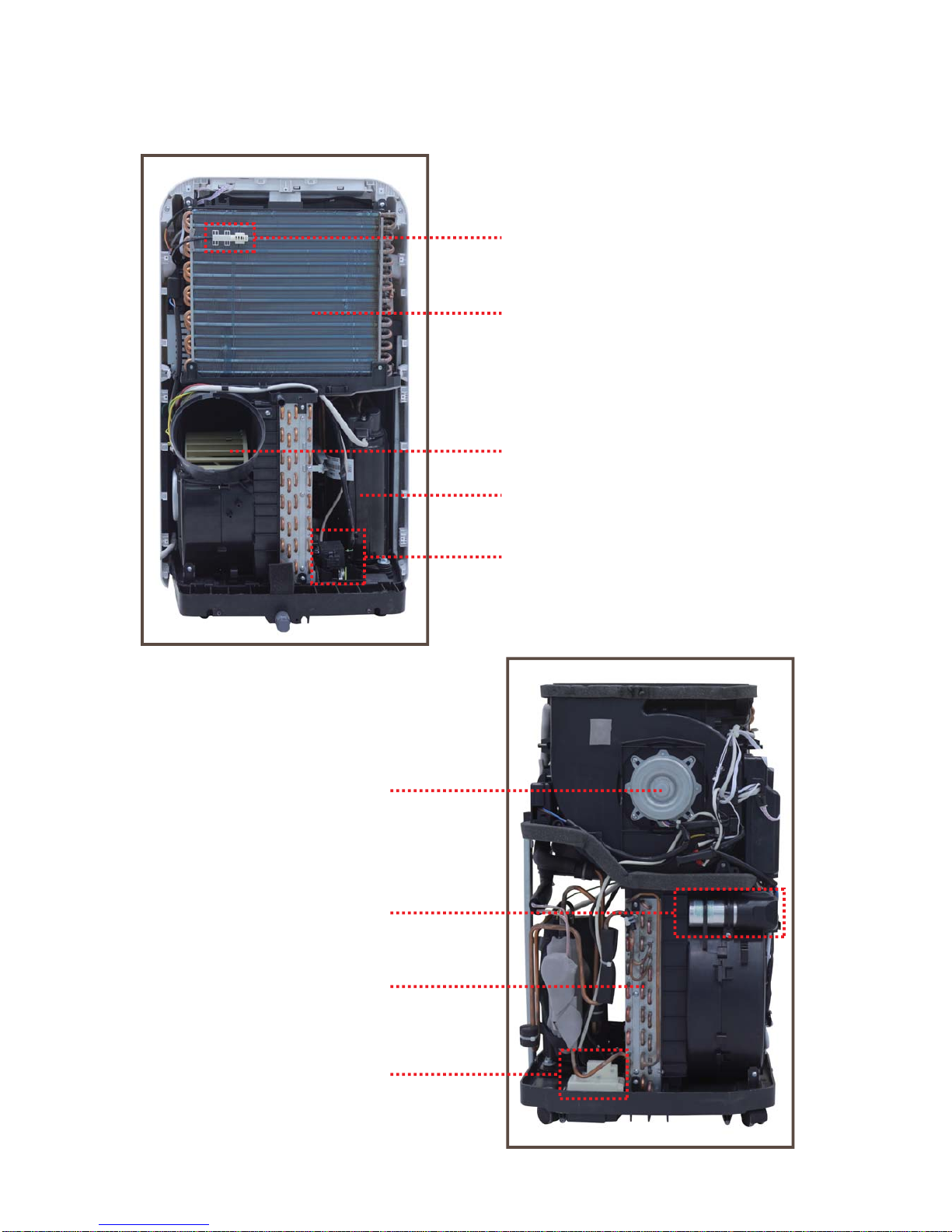
5. INTERNAL STRUCTURE
Temperature sensor
Evaporator
Centrifugal fan
Compressor
Water pump
Indoor fan motor
Capacitor of compressor
Condenser
Water level sensor
Page 15

Capacitor of fan motor
Electronic control box
Display board
Temperature sensor
Display board
Water level switch
Louver motor
Outdoor motor
Indoor motor
Relay
Power on/off
Page 16

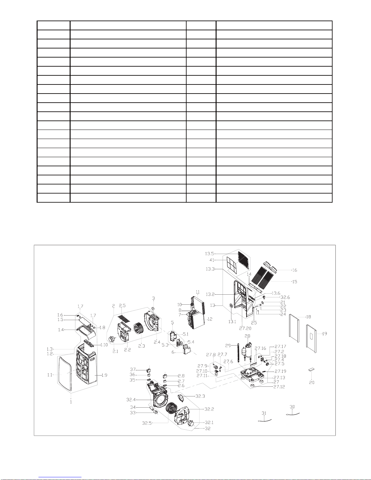
6. EXPLODED VIEW
6. 1 Single-hose model
1
11.
13.
14.
15.
16.
18.
19.
2
21.
22.
25.
3
24.
51.
52.
6
13
41
42
14
15
16
32 6.
21
22
23
24
29
28
27 8.
27 17.
27
27 2.
27 18.
27 5.
27 4.
27 7.
27 9.
27 10.
27 11.
27 6.
27 13.
27 12.
27 16.
31
32
32 1.
32 3.
32 2.
32 4.
34
33
35
36
37
110.
32 5.
39
39 1.
23.
17
40
19
18
53.
30
10
8
7
12
11
20
NO. Part name NO. Part name
1
Front panel assembly 3 Dobber
1.1
Front panel 5 Electronic control box assembly
1.2
Signal receiving board assembly 5.1 Electronic control box
1.3
Adorn board 5.2 Power module assembly
1.4
Upper panel 5.3 Main control board assembly
1.5
Horizontal louver 6 Cover of electronic control box
1.6
Bracket 7 Suction pipe assembly
1.7
Gear wheel 8 Discharge pipe assembly
1.7
Gear wheel 10 Capillary assembly
1.8
Louver motor 11 Evaporator coil assembly
1.9
Mid panel 12 Condenser assembly
1.10
Display box assembly 13 Rear panel assembly
2
Air outlet volute shell assembly 14 Connector of air exchaust duct
2.1
Asynchronous motor 15 Flexible air exhaust hose
2.2
Air outlet volute shell 16 Air exhaust passage
2.3
Centrifugal fan 17 Air exhaust passage
2.4
Cover of Air outlet volute shell 18 Window sealing board I
2.5
Air outlet grille 19 Window sealing board II
2.6
Fasten board of Capacitor 20 Remote controller
2.7
Capacitor of fan motor 21 Power cord cover
2.8
Capacitor box 22 Cover of drain connector
Page 17
23
Drain pipe 30 Pipe temperature sensor assembly
24
Drain stopper 31 Indoor temperature sensor assembly
24
Drain stopper 32 Air exhaust volute shell assembly
27
Chassis assembly 32.1 Asynchronous motor
27.2
Shaded pole motor 32.2 Cover of air exhause volute shell
27.4
Spring 32.3 Connector of air exchaust duct
27.5
Water wheel 32.4 Middle partition board
27.6
Water level sensor 32.5 Centrifugal fan
27.7
Bracket of water level sensor 32.6 Power cord
27.8
Micro switch 33 Capacitor box
27.9
Bracket of Micro switch 34 Capacitor of compressor
27.10
Dobber case 35 Fasten board of Capacitor
27.11
Dobber 36 Capacitor of fan motor
27.12
Universal wheel 37 Capacitor box
27.13
Chassis 39 Outdoor air inlet grille assembly
27.16
Waterproof foam 39.1 Outdoor air inlet grille
27.17
Top cover of Shaded pole motor 39.2 filter
27.18
Bottom cover of Shaded pole motor 40 Connector, air exchaust duct
28
Compressor 41 Top filter
29
Supporting bar 42 Indoor air inlet grille
6. 2 Dual-hose model
Page 18

NO.
Part name NO. Part name
1
Front panel assembly 19 Window sealing board II
1.1
Front panel 20 Remote controller
1.2
Signal receiving board assembly 21 Power cord cover
1.3
Adorn board 22 Cover of drain connector
1.4
Upper panel 23 Drain pipe
1.5
Horizontal louver 24 Drain stopper
1.6
Bracket 24 Drain stopper
1.7
Gear wheel 27 Chassis assembly
1.7
Gear wheel 27.2 Shaded pole motor
1.8
Louver motor 27.4 Spring
1.9
Mid panel 27.5 Water wheel
1.10
Display box assembly 27.6 Water level sensor
2
Air outlet volute shell assembly 27.7 Bracket of water level sensor
2.1
Asynchronous motor 27.8 Micro switch
2.2
Air outlet volute shell 27.9 Bracket of Micro switch
2.3
Centrifugal fan 27.10 Dobber case
2.4
Cover of Air outlet volute shell 27.11 Dobber
2.5
Air outlet grille 27.12 Universal wheel
2.6
Fasten board of Capacitor 27.13 Chassis
2.7
Capacitor of fan motor 27.16 Waterproof foam
2.8
Capacitor box 27.17 Top cover of Shaded pole motor
3
Dobber 27.18 Bottom cover of Shaded pole motor
5
Electronic control box assembly 27.19 Drain Connector
5.1
Electronic control box 27.20 Connecting board of chassis
5.2
Power module assembly 28 Compressor
5.3
Main control board assembly 29 Supporting bar
6
Cover of electronic control box 30 Pipe temperature sensor assembly
7
Suction pipe assembly 31 Indoor temperature sensor assembly
8
Discharge pipe assembly 32 Air exhaust volute shell assembly
10
Capillary assembly 32.1 Asynchronous motor
11
Evaporator coil assembly 32.2 Cover of air exhause volute shell
12
Condenser assembly 32.3 Connector of air exchaust duct
13
Rear panel assembly 32.4 Middle partition board
13.1
Cover for exhaust 32.5 Centrifugal fan
13.2
Rear panel 32.6 Power cord
13.3
Down filter 33 Capacitor box
13.6
Protective grille 34 Capacitor of compressor
14
Connector of air exchaust duct 35 Fasten board of Capacitor
15
Flexible air exhaust hose 36 Capacitor of fan motor
16
Air exhaust passage 37 Capacitor box
18
Window sealing board I 41 Top filter
Page 19

GD Midea Air-Conditioning Equipment Co.,Ltd
RAC Overseas Sales Company
Midea headquarter building,No.6 Midea Avenue
Beijiao, ShunDe, Foshan, GuangDong, P.R.C, 528311
Website: www.mideaaircon.com
Midea America Corporation, Customer Care Center
 Loading...