

Page 1

OI w I.IA
N
ENGLISH & ESPANOL
idea
Model: MPM3-10CR-BB6
Page 2

CONTENTS
SAFETY PRECAUTIONS
Always do this ..................................................................................................................................... 2
Never do this ........................................................................................................................................ 2
Electrical information .......................................................................................................................... 2
iDENTiFiCATiON OF PARTS
Accessories ........................................................................................................................................ 3
Names of parts .................................................................................................................................... 4
AiR CONDiTiONER FEATURES
Electronic control operating instructions ............................................................................................. 5
OPERATING iNSTRUCTiONS
Operating instructions ......................................................................................................................... 9
Operating condition ........................................................................................................................ 11
iNSTALLATiON iNSTRUCTiONS
Location ............................................................................................................................................. 11
Window kit installation ....................................................................................................................... 11
Exhaust hose installation .................................................................................................................. 14
CARE AND MAINTENANCE
Care and maintenance ..................................................................................................................... 15
TROUBLESHOOTING TiPS
Troubleshooting ................................................................................................................................ 16
NOTE
The rating data indicated on the rating label is based
on the testing condition of installing the un-extended
air exhaust duct without adaptor (The duct and the
adaptor are listed in the accessories chart of the
Instruction Manual).
Page 3

SAFETY PRECAUTIONS
To prevent injury to the user or other people and property damage, the following instructions must be
followed, Incorrect operation due to ignoring of instructions may cause harm or damage.
IO Always do this 1
Your air conditioner should be used in such a way
that it is protected from moisture, e.g. condensatior
splashed water, etc. Do not place or store your air
conditioner where it can fall or be pulled into water
or any other liquid. Unplug immediately.
• Always transport your air conditioner in a vertical
position and stand on a stable, level surface during
use.
• Turn off the product when not in use.
• Always contact a qualified person to carry out
repairs. If the supply cord is damaged it must be
repaired by a qualified repairer.
• Keep an air path of at least 30cm all around the
unit from walls, furniture and curtains.
• If the air conditioner is knocked over during use,
turn off the unit and unplug from the mains supply
immediately.
r
• Do not operate your air conditioner in a wet room
such as a bathroom or laundry room.
o Do not touch the unit with wet or damp hands or
when barefoot.
e Do not press the buttons on the control panel with
anything other than your fingers.
• Do not remove any fixed covers. Never use this
appliance if it is not working properly, or if it has
been dropped or damaged.
• Never use the plug to start and stop the unit.
• Always use the switch on the control panel.
• Do not cover or obsturct the inlet or outlet grilles.
• Do not use hazardous chemicals to clean or come
into contact with the unit. Do not use the unit in the
presence of inflammable substances or vapour such
as alcohol, insecticides, petrol,etc.
• Do not allow children to operate the unit
unsupervised.
• Do not use this product for functions other than
those described in this instruction manual.
\ 1
I(_ Neverdothis
I Energy Save t
• Use the unit in the recommended room size.
• Locate the unit where furniture cannot obstruct the air flow.
• Keep blinds/curtains closed during the sunniest part pf the day.
• Keep the filters clean.
• Keep doors and windows closed to keep cool air in and warm air out.
For your safety
• Do not store or use gasoline or other flammable vapors and liquids in the vicinity of this or any other
appliance.
® Avoid fire hazard or electric shock. Do not use an extension cord or an adaptor plug.
Do not remove any prong from the power cord.
Electrical information
• Be sure the electrical service is adequate for the model you have chosen. This information can be found
on the serial plate, which is located on the side of the cabinet and behind the grille.
• Be sure the air conditioner is properly grounded. To minimize shock and fire hazards, proper grounding is
important. The power cord is equipped with a three-prong grounding plug for protection against shock
hazards.
® Your air conditioner must be used in a properly grounded wall receptacle. If the wall receptacle you intend
to use is not adequately grounded or protected by a time delay fuse or circuit breaker, have a qualified
electrician install the proper receptacle.
® Ensure the receptacle is accessible after the unit installation.
Page 4

Accessories
iDENTiFiCATiON OF PARTS
PARTS "
N
©
PARTS NAME :
Air Outlet Tie-in
Air Outlet Pipe
Air Outlet Pipe Tie-in
Adaptor (for temporary duct mounting)
Band (For bundling the power cord)
Drain Hose(Continuous drainage)
Window Slider Kit II
Window Slider Kit I
Foam
Foam
PARTSNUMBER:
201125080107
201125000013
201125090064
201125090063
201125080113
201125190006
201125090002
201125090001
202125090082
202125090090
QUANTITY:
1
1
1
1
1
1
1
1
2
Remote Controller
Battery
o Check all the accessories are included in the package and please refer to the installation instructions for
their usage.
203355090205
202319900034
1
2
|qested tools for wi.dow kit i.stallatio.
1. Screwdriver(medium size Phillips)
2. Tape measure or ruler
3. Knife or scissors
4. Saw(In the event that the window kit needs to be cut down in size because
the window is too narrow for direct installation)
Page 5
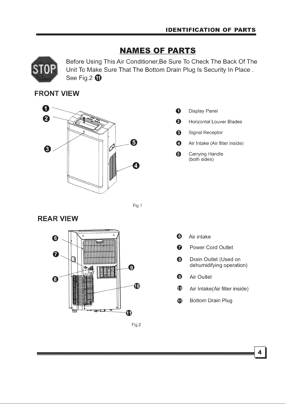
Before Using This Air Conditioner, Be Sure To Check The Back Of The
Unit To Make Sure That The Bottom Drain Plug Is Security In Place,
See Fig,2 _)
FRONT VIEW
iDENTiFiCATiON OF PARTS
NAMES OF PARTS
O
0
0
REAR VIEW
Q
@
O Display Panel
Horizontal Louver Blades
Signal Receptor
Air Intake (Air filter inside)
O Carrying Handle
(both sides)
Fig.1
O Air intake
O Power Cord Outlet
Drain Outlet (Used on
dehumidifying operation)
O Air Outlet
_:_ Air Intake(Air filter inside)
Bottom Drain Plug
Page 6
AiR CONDiTiONER FEATURES
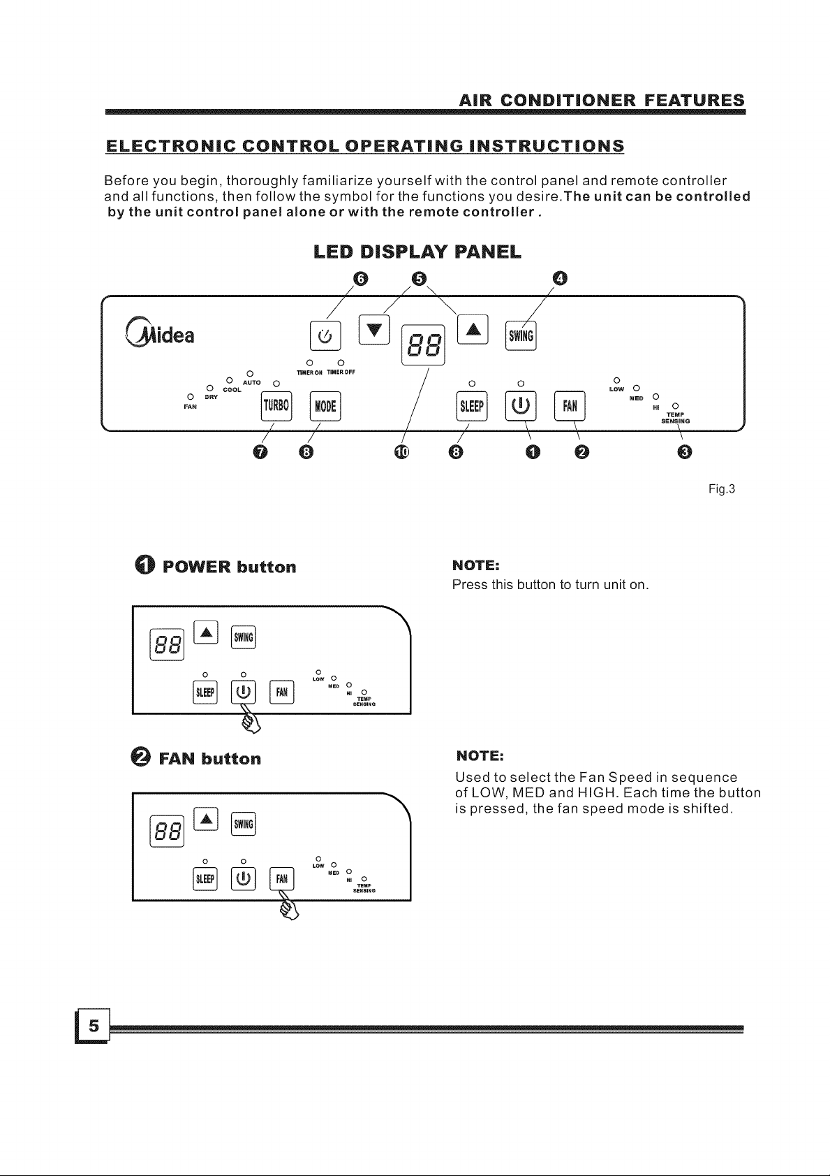
ELECTRONIC CONTROL OPERATING iNSTRUCTiONS
Before you begin, thoroughly familiarize yourself with the control panel and remote controller
and all functions, then follow the symbol for the functions you desire.The unit can be controlled
by the unit control panel alone or with the remote controller.
LED DISPLAY PANEL
o
O AUTO O
o
COOL
DRY
o
FAU
_) POWER button
o o L_2 o
_) FAN button
0 0
o
LOw O
MED O
Hi O
SENSING
TEMP
\
O
Fig.3
NOTE:
Press this button to turn unit on.
NOTE:
Used to select the Fan Speed in sequence
of LOW, MED and HIGH. Each time the button
is pressed, the fan speed mode is shifted.
O O
Page 7
AiR CONDiTiONER FEATURES
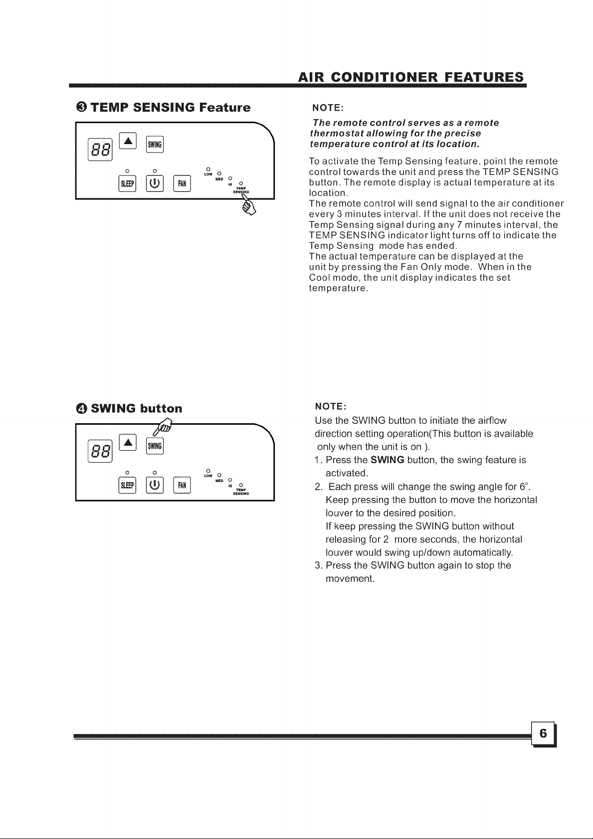
_) TEMP SENSING Feature
0 o
RE. O
HI TEC)p
SENT
NOTE:
The remote control serves as a remote
thermostat allowing for the precise
temperature control at its location.
To activate the Temp Sensing feature, point the remote
control towards the unit and press the TEMP SENSING
button. The remote display is actual temperature at its
location.
The remote control will send signal to the air conditioner
every 3 minutes interval. If the unit does not receive the
Temp Sensing signal during any 7 minutes interval, the
TEMP SENSING indicator light turns off to indicate the
TempSensing mode has ended.
The actual temperature can be displayed at the
unit by pressing the Fan Only mode. When in the
Cool mode, the unit display indicates the set
temperature.
0 SWING button
9
0 0
_E. O
HI O
SEN_INe
TeMe
NOTE:
Use the SWING button to initiate the airflow
direction setting operation(This button is available
only when the unit is on ).
1. Press the SWING button, the swing feature is
activated.
2. Each press will change the swing angle for 6°.
Keep pressing the button to move the horizontal
louver to the desired position.
If keep pressing the SWING button without
releasing for 2 more seconds, the horizontal
louver would swing up/down automatically.
3. Press the SWING button again to stop the
movement.
Page 8
AiR CONDITIONER FEATURES
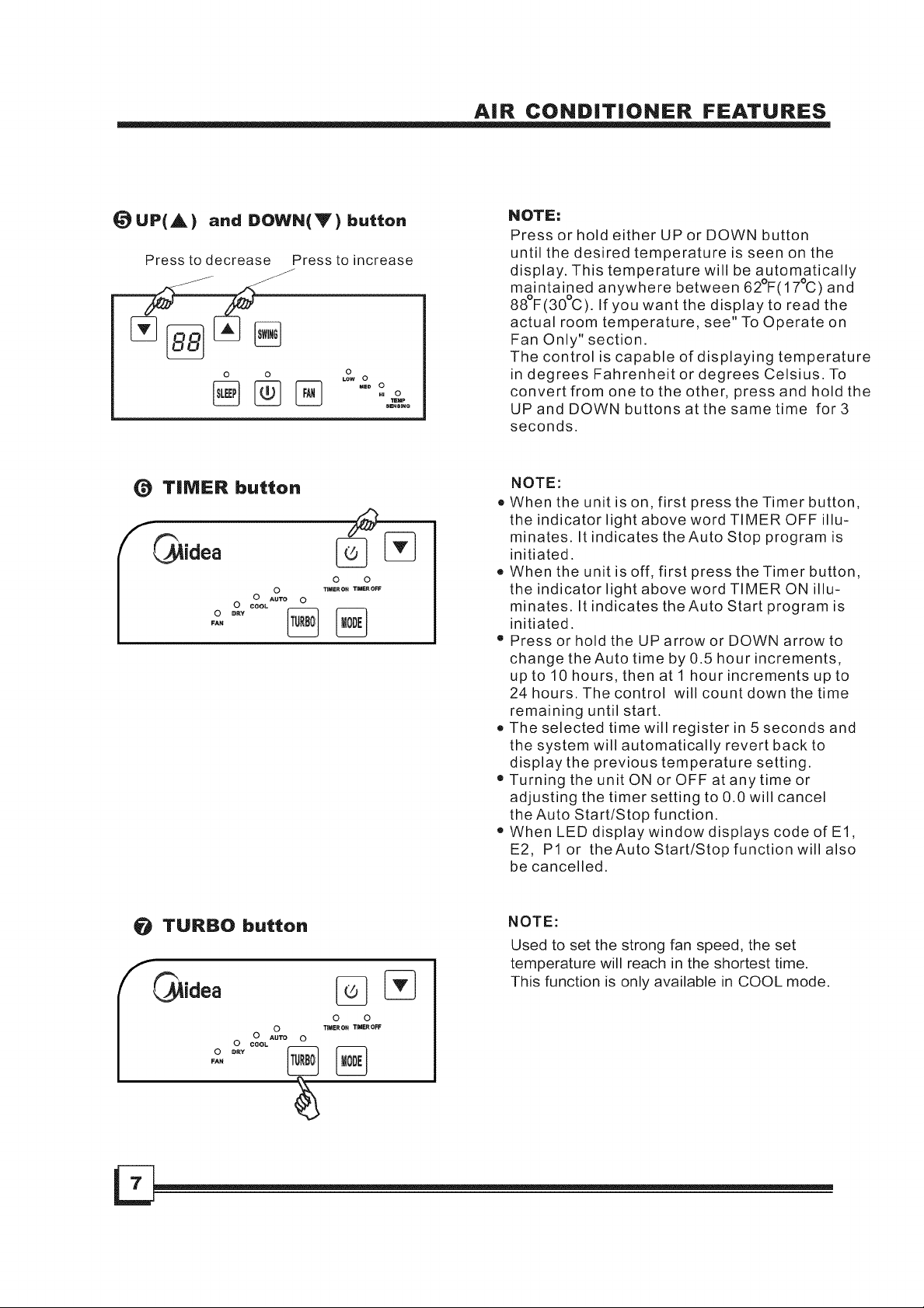
(_UP{A) and DOWN(Y) button
Press to decrease Press to increase
o o o
LOW 0
{_ TIMER button
0 0
TI_ER O_ TIMER OFF
%
FA_
0 _r_v
0 Au'ro 0
0 cool
0
HU 0
TEHP
SE_SINe
NOTE:
Press or hold either UP or DOWN button
until the desired temperature is seen on the
display. This temperature will be automatically
maintained anywhere between 62°F(17°C) and
88°F(30°C). If you want the display to read the
actual room temperature, see" To Operate on
Fan Only" section.
The control is capable of displaying temperature
in degrees Fahrenheit or degrees Celsius. To
convert from one to the other, press and hold the
UP and DOWN buttons at the same time for 3
seconds.
NOTE:
• When the unit is on, first press the Timer button,
the indicator light above word TIMER OFF illu-
minates. It indicates theAuto Stop program is
initiated.
• When the unit is off, first press the Timer button,
the indicator light above word TIMER ON illu-
minates. It indicates theAuto Start program is
initiated.
• Press or hold the UP arrow or DOWN arrow to
change the Auto time by 0.5 hour increments,
up to 10 hours, then at 1 hour increments up to
24 hours. The control will count down the time
remaining until start.
• The selected time will register in 5 seconds and
the system will automatically revert back to
display the previous temperature setting.
o Turning the unit ON or OFF at any time or
adjusting the timer setting to 0.0 will cancel
the Auto Start/Stop function.
• When LED display window displays code of El,
E2, P1 or theAuto Start/Stop function will also
be cancelled.
TURBO button
O TIMER 0_ TIMER ¢_FF
0 AUTO 0
0
FAN
NOTE:
Used to set the strong fan speed, the set
temperature will reach in the shortest time.
This function is only available in COOL mode.
O O
Page 9
AiR CONDITIONER FEATURES
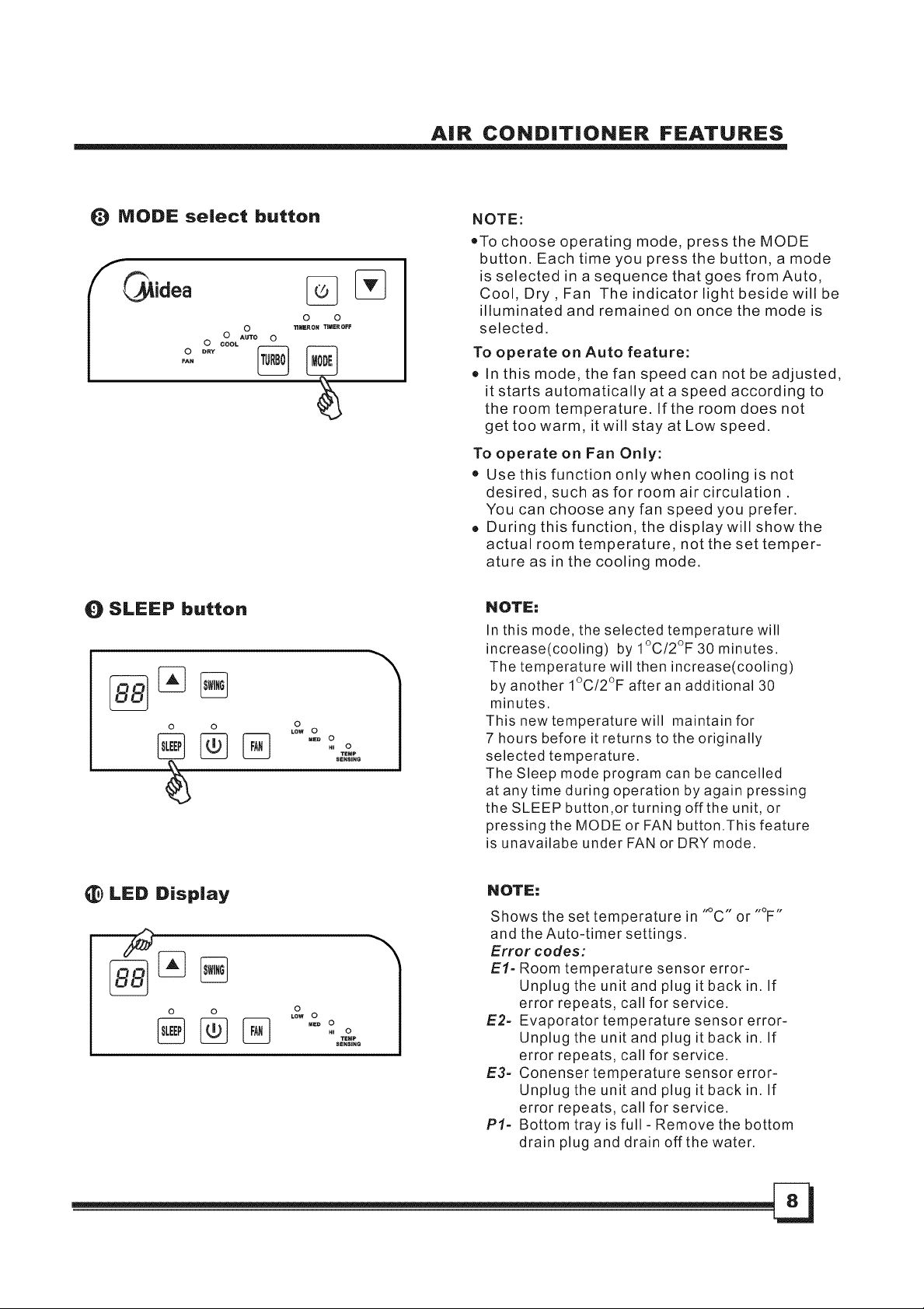
_) MODE select button
O
0 AUTO 0
0 COOL
FAN
Q SLEEP button
O O
% % ,O..oo
0 0
11MER ON TIMER OFF
.,ooo
NOTE:
oTo choose operating mode, press the MODE
button. Each time you press the button, a mode
is selected in a sequence that goes from Auto,
Cool, Dry, Fan The indicator light beside will be
illuminated and remained on once the mode is
selected.
To operate on Auto feature:
• In this mode, the fan speed can not be adjusted,
it starts automatically at a speed according to
the room temperature. If the room does not
get too warm, it will stay at Low speed.
To operate on Fan Only:
• Use this function only when cooling is not
desired, such as for room air circulation.
You can choose any fan speed you prefer.
• During this function, the display will show the
actual room temperature, not the set temper-
ature as in the cooling mode.
NOTE:
In this mode, the selected temperature will
increase(cooling) by 1°C/2°F 30 minutes.
The temperature will then increase(cooling)
by another 1°C/2°F after an additional 30
minutes.
This new temperature will maintain for
7 hours before it returns to the originally
selected temperature.
The Sleep mode program can be cancelled
at any time during operation by again pressing
the SLEEP button,or turning off the unit, or
pressing the MODE or FAN button.This feature
is unavailabe under FAN or DRY mode.
_) LED Display
O O
% % ,O..oo
.,ooo
NOTE:
Shows the set temperature in "_C" or "°F"
and the Auto-timer settings.
Error codes:
El- Room temperature sensor error-
Unplug the unit and plug it back in. If
error repeats, call for service.
E2- Evaporator temperature sensor error-
Unplug the unit and plug it back in. If
error repeats, call for service.
E3= Conenser temperature sensor error-
Unplug the unit and plug it back in. If
error repeats, call for service.
PI= Bottom tray is full- Remove the bottom
drain plug and drain off the water.
Page 10
OPERATING iNSTRUCTiONS
OPERATING iNSTRUCTiONS
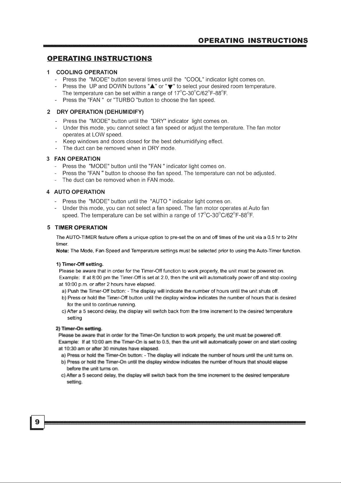
COOLING OPERATION
- Press the "MODE" button several times until the "COOL" indicator light comes on.
- Press the UP and DOWN buttons "A" or "y" to select your desired room temperature.
The temperature can be set within a range of 17°C-30°C/62°F-88°F.
- Press the "FAN " or "TURBO "button to choose the fan speed.
2
DRY OPERATION (DEHUMIDIFY)
Press the "MODE" button until the "DRY" indicator light comes on.
Under this mode, you cannot select a fan speed or adjust the temperature. The fan motor
operates at LOW speed.
Keep windows and doors closed for the best dehumidifying effect.
The duct can be removed when in DRY mode.
FAN OPERATION
Press the "MODE" button until the "FAN " indicator light comes on.
Press the "FAN " button to choose the fan speed. The temperature can not be adjusted.
The duct can be removed when in FAN mode.
AUTO OPERATION
Press the "MODE" button until the "AUTO " indicator light comes on.
Under this mode, you can not select a fan speed. The fan motor operates atAuto fan
speed. The temperature can be set within a range of 17°C-30°C/62°F-88°F.
TIMER OPERATION
The AUTO-TIMER feature offers a unique option to pre-set the on and off times of the unit via a 0.5 hr to 24hr
timer.
Note: The Mode, Fan Speed and Temperature settings must be selected prior to using the Auto-Rmer function.
1) Timer-Off setting.
Please be aware that in order for the Timer=Off function to work properly,the unit must be powered on.
Example: If at 8:00 pm the Timer-Off is set at 2.0, then the unit will automatically power off and stop cooling
at 10:00 p.m. or after 2 hours have elapsed.
a) Push the Timer-Off button: - The display will indicate the number of hours until the unit shuts off.
b) Press or hold the Timer-Off button until the display window indicates the number of hours that is desired
for the unit to continue running,
c)After a 5 second delay, the display will switch back from the time increment to the desired temperature
setting
Page 11

OPERATING iNSTRUCTiONS
0 WATER DRAINAGE:
During dehumidifying mode:
- Remove the drain plug from the back of the unit,attach a section of drain hose (included with
this unit) to the hole. Place the open end of the hose directly over the drain area in your
basement floor or in a water container (see Fig.4 & 5).
- You can also install the drain connector (5/8" universal female mender) with 3/4" hose (locally
purchased by consumer) for garden hose use.
NOTE:
- When the water level of the bottom tray reaches a predetermined level, the unit beeps 8 times,
the digital display area shows "PI" and the unit stops operation. Carefully move the unit to a drain
location, remove the bottom drain plug and let the water drain away (Fig.6). Restart the machine
until the "PI" symbol disappears. If the error repeats, call for service.
Remove the / Continuous
drain plug drain hose
Fig.4 Fig.5 Fig.6
Page 12

OPERATING iNSTRUCTiONS
OPERATING CONDiTiON
• The air conditioner must be operated within the ambient temperature range indicated below:
MODE ROOM TEMPERATURE
COOL 17°C~32°C / 62°F~92°F
DRY 13°C~32°C / 54°F~92°F
iNSTALLATiON iNSTRUCTiONS
iNSTALLATiON iNSTRUCTiONS
Location
® The air conditioner should be placed on a firm
foundation to minimize noise and vibration. For
safe and secure positioning, place the unit on a
smooth, level floor strong enough to support the unit.
o The unit has casters to aid placement, but it should
only be rolled on smooth, flat surfaces. Use caution
when rolling on carpet surfaces. Do not attempt to
roll the unit over objects.
• The unit must be placed within reach of a properly
rated grounded socket.
Vertical
window
4 41,
I -4- c::)
Window Slider Kit
Minim um:67.5cm(2.22ft).
Maxmum:123cm(4.04ft).
Horizontal "_
window
Window Slider Kit
Minimum:67.5cm(2.22ft).
Maxmum:123cm(4.04ft).
Fig.8
m
Fig.c
• Never place any obstacles around the air inlet or
outlet of the unit.
ti Allow at least 30cm(0.98ft) of space from the wall
for efficient air-conditioning.
• Do not use an extension cord.
Window kit installation
Your window kit has been designed to fit most
standard "Vertical" and "horizontal"window
applications, However, it may be necessary for you to
improvise/modify some aspects of the installation
procedures for certain types of window. Please refer
to Fig. 8& Fig.9 for minimum and maximum window
openings.
Note: If the window opening is less than the mentioned
minimum length of the window slider kit, cut that one
with holes in it short to fit for the window opening.
Never cut out the hole in window slider kit.
Page 13

eswe type)
27"~ 48" _ .....
t II__ Windowkit
iNSTALLATiON iNSTRUCTiONS
installation in double-hung sash windows
1. Cut the foam seal(adhesive type) to the proper length and
attach it to the window stool. Shown as in Fig.10.
Fig.10
2. Attach the window slider kit to the window stool. Adjust the
length of the window slider kit according to the width of
window, shorten the adjustable window kit if the width of
window is less than 27 inches.
Open the window sash and place the window slider kit on
the window stool. Shown as in Fig.11.
Foam seal
Window stool
Window stool
Fig.11
3. Cut the foam seal(adhesive type) to the proper length
and attach it on the top of the window. Shown as in Fig.12
Window kit
4. Close the window sash securely against the window.
Fig.12
5. Cut the foam seal to an appropriate length and sealing the
open gap between the top window sash and outer window
sash. Shown as in Fig.13.
Fig.13
Page 14

iNSTALLATiON iNSTRUCTiONS
|.stallatio. in a sliding sash windows
panel
Window
J Foam sealA
(adhesive type)
Fig.14
27"- 48"
Fig.15
1. Cut the foam seal(adhesive type) to the proper length and
attach it to the window frame. Shown as in Fig.14.
2. Attach the window slider kit to the window stool. Adjust the
length of the window slider kit according to the width of
window, shorten the adjustable window kit if the width of
window is less than 27 inches.
Open the window sash and place the window slider kit on
the window stool. Shown as in Fig.15.
3. Cut the foam seal(adhesive type) to the proper length
and attach it on the top of the window. Shown as in Fig.16.
4. Close the sliding sash securely against the window.
Foam seal
Fig.16
5. Cut the foam seal to an appropriate length and sealing the
open gap between the top window sash and outer window
sash. Shown as in Fig.17.
Fig.17
Page 15

iNSTALLATiON iNSTRUCTiONS
Exhaust hose installation:
The exhaust hose and adaptor must be installed or
removed in accordance with the usage mode.
Adaptor
Fig.16
Fig.17
Fig.18
COOL mode Install
FAN or DEHUMIDIFY mode Remove
1. Install the flexible Exhaust hose as depicted
in Fig.16 & 17.
2. Install the window Exhaust adaptor (flat mouth)
onto the exhaust hose as shown in Fig.18. Refer to
the previous pages for window kit installation.
Note:
The duct can be compressed or extended
moderately according to the installation
requirement, but it is desirable to keep the
duct length to a minimum.
iMPORTANT:
DO NOT OVER BEND THE DUCT (SEE Fig.19)
////
,11,
Fig.19
Page 16

Fig .20
v
Air fitter
Fitter tap
intake grille
CARE AND MAINTENANCE
CARE AND MAINTENANCE
IMPORTANT:
1) Be sure to unplug the unit before cleaning or
servicing.
2) Do not use gasoline, thinner or other chemicals to
clean the unit.
3)
Do not wash the unit directly under a tap or using a
hose. It may cause electrical danger.
4)
If the power cord is damaged, it should be repaired
by manufacturer or its agent.
1.
Air filter
Clean the air filter at least once two weeks to
prevent inferior fan operation because of dust.
Removal
Grasp the filter tab, pull the filter'Out" then'up'
Then remove the screw on the side air intake grille,
pull the filter out. See Fig.20.
Cleaninq
Wash the air filter by immersing it gently in warm
water(about 40°C/104°F) with a neutral detergent.
Rinse the filter and dry it in a shady place.
Mountinq
Replace the air filters.
Replacement air filter are available through the
Customer Service.
q_
Fig.21
CAUTION: Never operate the unit without the air
filter in place as this may result in damage to the
unit.
2. Unit enclosure
Use a lint-free cloth soaked with neutral detergent
to clean the unit enclosure. Finished by a dry clean
cloth.
3. Unit idle for a long time
- When you plan to leave this unit unused for a long
time, remove the bottom rubber plug from the back
hole and attach a section of the continuous drain
hose. All the water in the bottom tray would drain
outside through the drain hose.(See Fig.21 )
- Keep the appliance running on FAN mode for half
a day in a warm room to dry the appliance inside
and prevent mold forming.
- Stop the appliance and unplug it, wrapped the cord
and bundle it with the tape. Remove the batteries
from the remote controller.
- Clean the air filter and reinstall it.
- Disconnect the exhaust hose, keep it safety.
Page 17

TROUBLE SHOOTING
TROUBLESHOOTING TiPS
TROUBLES
1. Unit does not
Start when
Pressing on/off
Button
2. Not cool enough
3. Noisy or vibration
POSSIBLE CAUSES
Water full indicator blinks, water tank
is full.
Room temperature is lower than
the set temperature.(Cooling mode)
The windows or doors in the room
are not closed.
There are heat sources inside the
room.
Exhaust air duct is not connected or
blocked.
Temperature setting is too high. Decrease the set temperature.
- Air filter is blocked by dust. Clean the air filter.
The ground is not level or not flat
enough.
SUGGEST REMEDIES
Dump the water in the water tank.
Reset the temperature.
Make sure all the windows and
doors are closed.
Remove the heat sources if possible.
Connect the duct and make
sure it can function properly.
Place the unit on a flat, level
ground if possible.
4. Gurgling sound
5. Compressor does not work
and the digital display area
shows "P1"
6. The cooling indicator light
flashes at 1Hzand the digital
display area shows "El"
7. The FAN indicator light
flashes at 1Hz and the digital
display area shows "E2"
8. The Dehumidifying indicator
light flashes at 1Hz and the
digital display area shows
"E3"
The sound comes from the flowing
of the refrigerant inside the
air-conditioner.
The bottom tray is full
The room temperature Sensor is
off or short-circuit.
The Evaporator Temperature Sensor
is off or short-circuit.
The Condenser Temperature Sensor
is off or short-circuit.
It is normal.
Rremove the bottom plug and drain
the collected water away. If it does
not work after restart, contact the
service people.
Contact service people
Contact service people
Contact service people
Page 18

Your pr_ac,! i,Spro_e_ed by this °warranty:
&
&
#{_# _!a'# ......................_ '......._# %__, ...........
Page 19

N
ENGLISH & ESPANOL
de8
Modelo MPM3-1 3
Page 20

CONTENIDO
PRECAUCIONES DE SEGURIDAD
Siempre haga esto ........................................................................................................................... 2
Nunca haga esto .............................................................................................................................. 2
Informaci6n electrica ......................................................................................................................... 2
IDENDIFICACION DE LAS PARTES
Accesorios ........................................................................................................................................ 3
Denominaciones de las partes .......................................................................................................... 4
CARACTERISTICAS DEL AIRE ACONDICIONADO
Instruccionesde operaciondel controlelectr6nico............................................................................ 5
INSTRUCCIONES DE OPERACION
Instrucciones de operaci6n ............................................................................................................... 9
Oondici6n de operaci6n ......................................................................................................... 11
INSTRUCCIONES DE INSTALACION
Locaci6n ........................................................................................................................................... 11
Instalaci6n del kit de ventana .......................................................................................................... 11
Instalaci6n de la manguera de escape ........................................................................................... 14
CUIDO Y MANTENIMIENTO
Ouido y mantenimiento ................................................................................................................... 15
SOLUCIONES A PROBLEMAS
Soluciones a problemas .................................................................................................................. 16
NOTA
Los datos especificados indicados en la etiqueta de Clasificaci6n estan basados a
las condiciones de pruebas de instalar un ducto inextenso de escape del aire sin
adaptador (El ducto y el adaptador estan listadoes en la tabla de accesorios del
Manual de Instrucci6n).
Page 21

PRECA UCIONES DE SEGURIDAD
Para prevenir la lesi6n al usualrio o a otra gente y el da_o a la propiedad, las siguientes instrucciones
deben set obedecidas. La operaci6n incorrecta debida a la ignorancia de las instrucciones podria
causar da_o o averia.
(0 8iempre haga esto I
• Su aire acondicionado debe ser utilizado en
tal manera que esta protegido de la
humedad, e.g. Condesaci6n, agua
chapoteada, etc. No coloque o guarde su aire
acondicionado en donde el mismo se podria
caer o empujar en el agua o cualquier tipo de
liquido. Desenchufe de manera inmediata.
• Siempre transporte su aire acondicionado en
una posici6n vertical y mantenerlo de pie en
una superficie estable y nivelado durante su
operaci6n.
• Apague el producto cuando no Io usa.
® Siempre contacte a una persona calificada
para realizar la reparaci6n. Si el cable de
alimentaci6n esta estropeado, debe ser
reparado por un reparador calificado.
• Mantenga un espacio para el aire a por Io
menos 30cm entre la maquina y la pared, los
muebles y cortinas.
• Si el aire acondicionado es volcado durante
el uso, apague la maquina y desenchufelo
desde la toma de corriente inmediatamente.
I_) Nuncahagaesto _
• No use su aire acondicionado en un cuarto
hQmedo tal como un ba_o o un lavadero.
o No toque la maquina con la mano hQmeda o
mojada o con el pie descalzo.
o No empuje los botones en el panel de control con
nada masque sus dedos.
• No quite cualquier cubiertas fijadas. Nunca use
este aparato si no funciona adecuadamente, o si
ha sido botado o da_ado.
o Nunca use el enchufe para encender y apagar
esta maquina.
• Siempre use el interruptor en el panel de control.
o No cubra o obstruya la rejilla de la entrada o la
salida.
• No use el quimico azaroso para limpiar o
contactar con la maquina. No utilice la maquina
en la presencia de las subtancias inflamables o el
vapor tales como alcohol, insecticida, petroleo,
etc.
o No permita al ni_o operar la maquina sin
supervisi6n.
o No use este producto para nada mas las
funciones descritas en este manual de
instrucci6n.
Ahorro de energia
• Use esta maquina en un cuarto de area recomendada.
• Coloque esta maquina en donde los muebles no obstruyan el flujo del aire.
• Mantenga las persianas/cortinas cerradas durante la parte que mas soleada del un dia.
o Mantenga los filtros limpios.
e Mantenga las puertas y ventanas cerradas para guardar el aire frio dentro.
Para su seguridad
• No guarde o use la gasolina o otros vapores y liquidos inflamables en el alrededor de esta maquina
o cualquier.
e Evite el azar de fuego o choque electrico. No use un cable extendido o un enchufe adaptador
hembra. No quite ninguna toma desde el cable de alimentaci6n.
Informacibn El_ctrica
o
AsegQrese de que el servicio electrico es adecuado para el modelo que usted ha seleccionado.
Esta informaci6n puede ser encontrada en la placa serial, que es ubicada en el lado de el gabinete
y detras de las rejillas.
• AsegQrese de que el aire acondicionado esta conectado con tierra correctamente. A los fines de
minimizar los riesgos de choque y fuego, la conexi6n correcta con tierra es muy importante. El
cable de alimentaci6n es equipado con un enchufe mancho a tierra de tres tomas para la protecci6n
contra los riesgos del choque electrico.
o Su aire acondicionado debe ser usado con una toma de corriente en la pared correctamente a tierra.
Si el enchufe hembra en la pared que usted va a utilizar no esta conectado correctamente con tierra
o protegido pot un fusible de atraso de tiempo o un disyuntor del circuito, ha de acudir a un
electricista para instalar la toma de corriente adecuada.
• AsegQrese de que la toma de corriente es accesible despues de la instalaci6n de la maquina.
Page 22

Accesorios
IDENTIFICACION DE LAS PARTES
PARTES: NRO. PARTES CANT
(_ 201125090063 1
z h
DENOMINACION
Lazo de salida del aire
Tuberia de salida del aire
Lazo del tubo de aire
Adaptador (para el montaje del ducto
temporal)
Banda (para atar el cable de
alimentaci6n)
Manguera de desagQe (desagQe
continuo)
Kit del Aparato Deslizante de Ventana II
Kit del Aparato Deslizante de Ventana I
Espuma
Espuma
201125080107 1
201125000013 1
201125090064 1
201125080113
201125190006
201125090002
201125090001
202125090082
202125090090
1
1
1
1
1
2
Mando a distancia
Baterias
• Chequee todos los accesorios si estan incluidos en el paquete y por favor refierase alas
instrucciones de instalaci6n para su uso.
203355090205
202319900034
1
2
Herramientas recomendadas para la instalalcibn del Kit de Ventana
1. Destornillador (tipo Phillips de medio tama_o)
2. Cinta metrica o regla
3. Cuchillo o tijeras
4. sierra (en caso de que el Kit de Ventata necesita ser cortado en cierto tama_o si la ventana es
demasiado extrecha para la instalaci6n directa)
12_................................................................................................................................................................................................................................................................................................................---
Page 23

DENOMINACIONES DE LAS PARTES
Antes del uso de este Aire Acondicionado, aseg(_rese de chequear la parte
trasera de la m&quina para confirmar que el Tap6n de DesagQe Inferior
est& asegurado en posici6n. Vea Fig. 2 (Ill.
APARENCIA DELANTERA
O
IDENTIFICA CION DE PARTES
I_I Panel de Control
O Tabillas Horizontales
0 Receptor de sepal
O Acceso de aire
I!_ Agarradera de traslado
(ambos lados)
APARENCIA TRASERA
O
@
Fig.1
Entrada del Aire
O Salida del Cable de Alimentaci6n
_I Salida de DesagQe
Salida del Aire
(I}) Entrada delAire
Ii_ Tap6n de DesagQe inferior
-@
Fig.2
Page 24

CARA CTERIS TICA S DEL AIRE A CONDICIONA D0
INSTRUCCIONES DE OPERACION DEL CONTROL ELECTR6NICO
Antes del uso, conozca el panel de control y el mando a distancia y todas sus funciones, despues, siga
los simbolos para las funciones que usted desee. La maquina puede set controlada por solo el panel
de control o con el mando a distancia.
PANEL DE DISPLAY DE LED
_idea
O AUTO O
O COOL
O DRY
FAN
O Bot6n POWER
O O
o
/ /
/ /
0 Q
0 0 _
o ©
TIMER ON TIk_ER OFF
...oo
L°..Oo
0
o o o
/ \ \ \
/ \ \ \
LOW 0
..oo
HI O
SENSING
TEMP
0 0 0 0
NOTA:
Oprima este bot6n para encender la maquina.
Fig.3
Bot6n FAN
O
o o
NOTA:
Usado para seleccionar la Velocidad del Ventilador ub
secuencia de - Bajo, Media, Alta .Cada tiempo que
el bot6n sea comprimido, el modo la velocidad del
ventilador se cambia.
...oo
Page 25

CARACTERISTICAS DEL AIRE ACONDICIONADO
FUNCION TEMP SENSING
O O
LOW 0
MeD 0
O
HI TOp
SENS_
NOTA:
El mando a distancia sirve come un termostato
remote permitiendo el control de precision de la
temperatura en su Iocalidad.
Para activar la funcion TEMP SENSING, apunte el
mando a distancia hacia la maquina y oprima el
boton Temp Sensing. El display del mando es la
temperatura actual de su Iocalidad. El mando a
distancia enviara la sepal al aire acondicionado
cada 3 minutos. Si la maquina no recibe la sepal
de Temp Sensing durante 7 minutos, la luz del
indicador de TEMP SENSING se apagara para
ense_ar que la funci6n Temp Sensing ha acabado.
La temperatura actual puede ser ense_ada en la
maquina si se oprime el modo Fan Only. Cuando
bajo el modo Cool, el display de la maquina
indicara la temperatura configurada.
Q Botbn SWING
O O
uEo 0
HI TOp
SENSING
Use el bot6n SWING para iniciar la operaci6n de la
configuraci6n de la direcci6n del flujo del aire (Este
bot6n es disponible Qnicamente cuando la maquina
esta encendida).
1. Oprima el bot6n SWING, la funci6n de
oscilaci6n esta activa.
2. Cada oprimida del bot6n cambiara el angulo de
oscilaci6n a 6°. Mantenga oprimiendo el bot6n
para mover la tabilla a la posici6n deseada.
Si se mantiene oprimiendo el bot6n SWING sin
liberarlo por mas de 2 segundos, la tabilla
horizontal oscilara hacia arriba/abajo
automaticamente.
3. Oprima el bot6n SWING otra vez para cesar el
movimiento.
Page 26

CARA CTERISTICAS DEL AIRE ACONDICIONADO
O Botones UP y DOWN
Oprimir para decrecer Oprimir para incrementar
0 0 o
Low 0
..oo
Hi O
SeNSlNe
TeMP
(_)Botbn TIMER
idea
o o
FAN
0 TIMER ON TIMER OFF
O AUTO O
O cool
NOTA:
Oprima o mantenga oprimiendo el botSn UP
(ARRIBA) o DOWN (ABAJO) hasta que la
temperatura deseada se demuestre en el display.
Esta temperatura automaticamente sera mantenida
dondequiera entre 62°F (17°C) y 88°F(30°C). Si usted
desea que el display demuestre la temperatura actual
del cuarto, vea la secciSn "A Operar en Fan $51o".
El control es capaz de visualizar la temperatura en
grado Fahrenheit o Celsius, para convertir de uno a
otro, optima y mantenga comprimiendolo los botones
UP y DOWN al mismo tiempo por 3 segundos.
NOTA:
• Cuando la m&quina est& funcionando, primero
oprima el bot6n Timer, y la luz del indicador
arriba de la palabra TIMER OFF se enciende, Io
que indica que el programa Auto Stop est&
iniciado.
• Cuando la m&quina est& apagada, primero
oprima el bot6n Timer, y la luz del indicador
arriba de la palabra TIMER ON se enciende, Io
que indica que el programa Auto Start est&
iniciado.
• Optima o mantenga oprimiendo la flecha UP
(ARRIBA) o la DOWN (ABAJO) para cambiar el
tiempo de Auto por el incremento desde 0.5
hora, hasta 10 horas, despues, desde 1 hora
hasta 24 horas. El control contar& hacia atr&s el
tiempo quedado hasta que la m&quina se
arranca.
• El tiempo seleccionado se registrar& en 5
segundos y el sistema automaticamente
revertir& hacia atr&s a enseSar la configuraci6n
anterior de temperatura.
• Hacer la m&quina est& ON o OFF a cualquier
hora o ajustar la configuraci6n del timer
(cronometrador) a 0.0 podr& cancelar la funci6n
Auto Star/Stop.
• Cuando el display LED enseSa Ios c6digos
El, E2 o P1, la funci6n Auto Star/Stop ser&
cancelada.
Page 27

CARACTERISTICAS DEL AIRE ACONDICIONADO
Boton TURBO
O O
FAN
0 DRY
0 TruER ON TIMER OFF
0 AUTO 0
0 cool
Boton de Seleccion de MODO
0 TIMER ON TIMER OFF
_u_('_OL AUTO 0
0
NOTA:
Se utiliza para fijar la fuerte velocidad del
ventilador, la temperatura alcanzar_ en el
plazo m_s breve. Esta funci6n s61o est_
disponible en el modo de enfriar.
NOTA:
• Para seleccionar el modo de operaci6n, optima
el bot6n MODO. Cada vez que usted opdme
este bot6n, un modo sera seleccionado en una
sequencia que viene desde Auto, Cool, Dry,
Fan, y la luz del indicador al lado estara
iluminada y mantendra encendida una vez el
modo sea seleccionado.
Para operar la funcion Auto:
• Bajo este modo, la velocidad del ventilador no
puede set ajustada, y se comienza
automaticamente a una velocidad conforme a la
temperatura del cuarto. Si el cuarto no esta tan
caluloso, el ventilador mantendra una velocidad
Baja.
Para operar la funcion Fan Only:
• Use esta funci6n Onicamente cuando no se
quiere el resfriamiento, sino para la circulaci6n
del aire del cuarto. Usted puede seleccionar
cualquier velocidad del ventilador que desee.
• Durante esta funci6n, el display no enseSara la
temperatura configurada como bajo el modo
Cooling, sino la temperatura actual del cuarto.
O SLEEP button
SENSING
NOTA:
Bajo este modo, la temperatura seleccionada
incrementara (cooling) a 1°C/2°F en 30 minutos.
La temperatura incrementara a otro 1°C/2°F luego de
otros 30 minutos adicionales.
Esta nueva temperatura mantendr& pot 7 horas antes
de que se retorne a la temperatura ofiginalmente
seleccionada.
El programa del Modo Sleep (Dormida) puede set
cancelado a cualquier hora durante su funcionamiento
con oprimir otra vez el bot6n SLEEP, o apagar la
m&quina, o oprimir el bot6n MODE o FAN. Esta
funci6n no se puede realizar bajo el modo FAN o DRY.
Page 28
INSTRUCCIONES DE OPERA CION
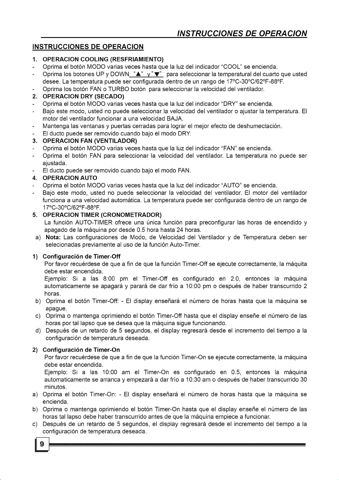
INSTRUCCIONES DE OPERACION
,
OPERACION COOLING (RESFRIAMIENTO)
Oprima el bot6n MODO varias veces hasta que la luz del indicador "COOL" se encienda.
Oprima los botones UP y DOWN "A" y"V _'_para seleccionar la temperatural del cuarto que usted
desee. La temperatura puede ser configurada dentro de un rango de 17°C-30°C/62°F-88°F.
Oprima los bot6n FAN o TURBO bot6n para seleccionar la velocidad del ventilador.
2.
OPERAClON DRY (SECADO)
Oprima el bot6n MODO varias veces hasta que la luz del indicador "DRY" se encienda.
Bajo este modo, usted no puede seleccionar la velocidad del ventilador o ajustar la temperatura. El
motor del ventilador funcionar a una velocidad BAJA.
Mantenga las ventanas y puertas cerradas para Iograr el mejor efecto de deshumectaci6n.
El ducto puede ser removido cuando bajo el modo DRY.
3.
OPERAClON FAN (VENTILADOR)
Oprima el bot6n MODO varias veces hasta que la luz del indicador "FAN" se encienda.
Oprima el bot6n FAN para seleccionar la velocidad del ventilador. La temperatura no puede ser
ajustada.
El ducto puede ser removido cuando bajo el modo FAN.
4.
OPERAClON AUTO
Oprima el bot6n MODO varias veces hasta que la luz del indicador "AUTO" se encienda.
Bajo este modo, usted no puede seleccionar la velocidad del ventilador. El motor del ventilador
funciona a una velocidad automatica. La temperatura puede ser configurada dentro de un rango de
17°C-30°C/62°F-88°F.
,
OPERAClON TIMER (CRONOMETRADOR)
La funci6n AUTO-TIMER ofrece una 5nica funci6n para preconfigurar las horas de encendido y
apagado de la maquina por desde 0.5 hora hasta 24 horas.
a)
Nota: Las configuraciones de Modo, de Velocidad del Ventilador y de Temperatura deben ser
selecionadas previamente al uso de la funci6n Auto-Timer.
1) Configuracion de Timer-Off
Por favor recuerdese de que a fin de que la funci6n Timer-Off se ejecute correctamente, la maquita
debe estar encendida.
Ejemplo: Si a las 8:00 pm el Timer-Off es configurado en 2.0, entonces la maquina
automaticamente se apagara y parara de dar frio a 10:00 pm o despues de haber transcurrido 2
horas.
b) Oprima el bot6n Timer-Off: - El display ensefiara el nSmero de horas hasta que la maquina se
apague.
c) Oprima o mantenga oprimiendo el bot6n Timer-Off hasta que el display ensefie el nSmero de las
horas portal lapso que se desea que la maquina sigue funcionando.
d) Despues de un retardo de 5 segundos, el display regresara desde el incremento del tiempo a la
configuraci6n de temperatura deseada.
2) Configuracion de Timer-On
Por favor recuerdese de que a fin de que la funci6n Timer-On se ejecute correctamente, la maquina
debe estar encendida.
Ejemplo: Si alas 10:00 am el Timer-On es configurado en 0.5, entonces la maquina
automaticamente se arranca y empezara a dar frio a 10:30 am o despues de haber transcurrido 30
minutos.
a) Oprima el bot6n Timer-On: - El display ensefiara el nSmero de horas hasta que la maquina se
encienda.
b) Oprima o mantenga oprimiendo el bot6n Timer-On hasta que el display enseSe el nSmero de las
horas tal lapso debe haber transcurrido antes de que la maquina empiece a funcionar.
c) Despues de un retardo de 5 segundos, el display regresara desde el incremento del tiempo a la
configuraci6n de temperatura deseada.
Page 29

INSTRUCCIONES DE OPERACION
3) Configuracion de Timer-On y Timer-Off
La maquina tambien permite seleccionar simutaneamente tanto el tiempo de inicio como de apagado.
Nota: - La maquina debe ser apagada antes de configurar esta funci6n.
Ejemplo: Si alas 7:00 am el Timer-On es configurado en 2.5, y el Timer-Off a 10, entonces la maquina
automaticamente se arrancara y empezara a dar frio a 9:30 am y continua funcionando hasta las 5:00
pm a tal hora parara de dar frio y se apagara.
a) Comience siguiendo las instrucciones para el Timer-On como Io desctrito arriba (2), luego, de
manera inmediata seleccione el tiempo del Timer-Off como Io descrito arriba (1). No optima el bot6n
POWER durante el proceso, si no, la configuraci6n sera cancelada.
b) Despues de un retardo de 5 segundos, el display regresara desde el incremento del tiempo a la
configuraci6n de temperatura deseada.
4) Configuracion de Timer-Off y Timer-On
La maquina tambien permite seleccionar simutaneamente tanto el tiempo de apagado como de inicio.
Nota: - La maquina debe set encendida antes de configurar esta funci6n.
Ejemplo: Si a las 8:00 am el Timer-Off es configurado en 2.5, y el Timer-On a 8, entonces la maquina
automaticamente se apagara arranca y cesar la funci6n a 10:30 am y se arrancara a las 4:00 pm, a
partir de tal hora continuara funcionando.
a) Comience siguiendo las instrucciones para el Timer-Off como Io descrito arriba (1), luego, de
manera inmediata seleccione el tiempo del Timer-On como Io desctrito arriba (2). No opdma el bot6n
POWER durante el proceso, si no, la configuraci6n sera cancelada.
b) Despues de un retardo de 5 segundos, el display regresara desde el incremento del tiempo a la
configuraci6n de temperatura deseada.
IMPORTANTE:
• El tiempo se registrara en 5 segundos (despu_s de oprimir el boton UP/DOWN), entonces
usted puede continua oprimiendo el boton hasta que el tiempo que desea est_ establecido; si
no, tiene que repetir los pasos de nuevo.
S. DESAGUE
Bajo el modo de deshumectacion:
- Quite el tap6n de desagL_e desde la parte trasera de la maquina, adjunte una secci6n de la
manguera de desagL_e (incluida con esta maquina) al agujero. Coloque el extremo abierto de la
manguera directamente sobre la area de desagL_e en el suelo o en un dep6sito de agua (ver Fig. 4 y
5).
- Usted puede tambien instalar el conectador de desagOe (zurcidor hembra universal de 5/8") con la
manguera de 3/4" (adquirida por el cliente en su Iocalidad) para el uso de desagL_e del jardin.
NOTA:
- Cuando el nivel del agua de la bandeja abajera alcanza al un nivel predeterminado, la maquina dara
el pitido 8 veces, el display digital enseSara "PI" y la maquina parara la operaci6n. Mueve con
cuidado la maquina a un lugar para el desagL_e, quite el tap6n inferior de desagiJe y deje el agua se
agote (Fig. 6). Reinicie la maquina hasta que el signo "PI" se desaparezca. Si el error repite, haga la
Ilamada para el servicio.
Quitar et tap6n
de desagOe
Manguera de
;aq{Jecontinua
Fig.4 Fig.5 Fig.6
Page 30

INSTRUCCIONES DE OPERA CION
CONDICIbN DE OPERACIbN
• El aire acondicionado debe ser utilizado dentro del rango de la temperatura ambiental indicada
como siguiente:
MODO TEMPERATURA DEL CUARTO
COOL 17°C-32°C / 62°F-92°F
DRY 13°C-32°C / 54°F-92°F
INSTRUCCIONES DE INSTALACION
INSTRUCCIONES DE INSTALACION
Locaci6n
• El aire acondicionado debe ser colocado en un asentamiento
firme para minimizar el ruido y la vibraci6n. Para la seguridad
y asegurar posicionamiento, coloque la maquina en el suelo
suave, nivelado y fuerte suficiente para soportar el aparato.
• La maquina tiene ruedas para ayudar el posicionamiento,
Fig.7
ventana
4
Vertical
pero las mismas deben ser utilizadas sobre la superficie
suave y plana. Ponga en alerta cuando estan rodando sobre
las superficies de la alfombra. No trate de rodar a maquina
pasando por cualquier objetos.
• La maquina debe ser colocada dentro del alcance de una
toma de corriente nominal correcta.
Kit De Ventana
Minima:67.5cm(2.22ft).
M&xima: 123cm(4.04ft).
Horizontal
ventana
° 0
Kit De Ventana
Minima:67.5cm(2.22ft).
M_xima: 123cm(4.04ft).
Fig.8
g
• Nunca coloque los obstaculos alrededor de la entrada o la
salida del aire de la maquina.
• Se deja un espacio por Io menos de 30cm (0.98 pie) desde la
pared para Iograr un eficiente funcionamiento del aire
acondicionado.
• No use el cable de extensi6n.
Instalacibn del kit de ventana
El kit de ventana ha sido diseSado para adaptar la mayoria de
las ventanas "Vertical" y "horizontal" estandares. Sin embargo,
podria ser necesario para usted que improvise/modifique
algunos aspectos del procedimiento de la instalaci6n para
ciertos tipos de ventanas. Por favor refierase alas Fig. 8 y Fig. 9
para la informaci6n de la abertura minima y m_xima de la
ventana.
Nora: Si la abertura de la ventana es menor que la Iongitud
minima mencionada del kit deslizante de la ventana, c6rtelo con
ajugeros en su corto para quedarse con la abertura de la
ventana. Nunca corte el kit deslizante de ventana fuera del
agujero de si mismo.
Page 31

INSTRUCCIONES DE INSTALACION
Instalacibn en la ventana de faja tipo doble-hung
1. Corte el sello de espuma (tipo adhesivo) a una Iongitud
adecada y peguelo en la banca de la ventana. Fig. 10
adheswo)
Fig.10
_[__-__ __Ki_t De Ventana
Fig.11
_ De Ventana
2. djunte el kit deslizante de ventana en la banca de la ventan.
Ajuste la Iongitud del kit deslizante de ventana de acuerdo
con la anchura de la ventana, acorte el kit de ventana
ajustable si la anchura de la ventana es menor de 27
pulgadas.
Abra la faja de la ventana y coloque el kit deslizante de
ventana en la banca de la ventana. Fig. 11
3. Corte el sello de espuma (tipo adhesivo) a una Iongitud
adecuada y peguelo en el tope de la ventana. Ense_ado en
Fig. 12
4. Cierre la faja de la ventana firmemente contra la ventana.
5. Corte el sello de espuma a una Iongitud adecuada y selle el
espacio abierto entre la faja superior de a ventana y la faja
externa de la ventana. Ense_ado en Fig. 13
Sello De Espuma
Ventana De Heces
Fig.12
Fig.13
Page 32

Ventana
Kit De
Sello De Espuma
(tipo adhesivo)
Fig.14
_-7"-48"
Fig.15
INSTRUCCIONES DE INSTALACION
Instalacibn en la ventana de faja deslizante
1. Corte el sello de espuma (tipo adhesivo) a una Iongitud
adecada y peguelo en la banca de la ventana. Ver la Fig. 14
,
Adjunte el kit deslizante de ventana en la banca de la ventan.
Ajuste la Iongitud del kit deslizante de ventana de acuerdo
con la anchura de la ventana, acorte el kit de ventana
ajustable si la anchura de la ventana es menor de 27
pulgadas.
Abra la faja de la ventana y coloque el kit deslizante de
ventana en la banca de la ventana. Fig. 15
,
Corte el sello de espuma (tipo adhesivo) a una Iongitud
adecuada y peguelo en el tope de la ventana. Ense_ado en
Fig. 16
Sello De
Espuma
Fig.16
Fig.17
4. Cierre la faja deslizante de la ventana firmemente contra la
ventana.
,
Corte el sello de espuma a una Iongitud adecuada y selle el
espacio abierto entre la faja superior de a ventana y la faja
externa de la ventana. Ense_ado en Fig. 17.
Page 33

%
INS TRUCCIONES DE INS TALA CION
Instalacibn de la manguera de escape
La manguera de desagQe y el adaptador deben ser
instalados o desmontados de acuerdo con el modo
de uso
Fig.16
Fig.17
)tot
Fig.18
Modo COOL Instalar
Modo FAN o DEHUMIDIFY Desmontar
1. Instale la manguera flexible de DesagOe como Io
demostrado en las Fig. 16 y Fig. 17.
,
Instale el adaptador de DesagOe de la ventana
(boca plana) en la manguera de desagOe como
Io demostrado en la Fig. 18. Refierase a la
pagina anterior para la informaci6n de la
instalalci6n del kit de ventana.
NOTA:
• El conducto puede ser comprimido o extendido
con moderaci6n conforme al requisito de
instalaci6n, pero es deseable que se mantenga
la Iongitud del conducto a su minimo.
Fig.19
IMPORTANTE:
NO DOBLE DEMASIADO EL CONDUCTO (VER
Fig. 19)
Page 34

Fig.20
Esta maquina
tiene dos flltros.
Filtro del aire
Entrada det Aire
CUIDO Y MANTENIMIENTO
CUIDO Y MANTENIMIENTO
IMPORTANTE:
1) AsegQrese de desenchufar la maquina antes de la limpieza o el
servicio.
2) No use la gasolina, diluyente o otros quimicos para limpiar la
maquina.
3) No lave la maquina directamente bajo un grifo o utilizando una
manguera, Io que podria causar peligro electrico.
4) Si el cable de alimentaci6n esta averiado, debe ser reparado por
el manufacturador o su agente.
1. Filtro del aire
- Limpie el filtro del aire por Io menos una vez a cada dos
semanas para prevenir la operaci6n inferior del ventilador
debido al polvo.
- Quite
Esta maquina tiene dos filtros. Agarre la lengOeta del filtro jale
afuera el filtro. Saque el filtro de abajo aflojando los tornillos
y quitando la rejilla de entrada del aire, y luego, saque el filtro
del aire como Io demostrado en las Fig. 20.
- Limpieza
Lave el filtro del aire inmergiendolo con gentileza en el agua
calida (aprox. 40°C/104°F) con detergente neutral. Enjuague y
seque el filtro en un lugar con sombra.
- Montaie
Inserte el filtro de arriba hacia arriba despues la limpieza,
adjunte el filtro de abajo en la rejilla de entrada del aire, luego,
instale la rejilla con los tornillos.
2. Valla de la maquina
- Use un trapo de hilacha mojado con el detergente neutral para
limpiar la valla de la maquina y acabar la limpieza con un trapo
seco y limpio.
Fig.21
3. Maquina sin uso por largo tiempo
- Quite el tap6n de goma encontrado en la parte trasera de la
maquina y adjunte la manguera a la salida de desagOe. Coloque
el extremo abierto de la manguera directamente sobre la area
de desagOe en su suelo (Ver Fig. 4 y 5).
- Quite el tap6n desde la salida abajera de desagOe, toda la agua
en la bandeja abajera se agotara (Ver Fig. 6).
- Mantenga la maquina funcionando bajo el modo FAN por medio
dia en un cuarto calido para secar Io interior de la maquina y
evitar el moho.
- Pare y desenchufe la maquina, envuelva el cable y atelo con
una cinta. Quite las baterias desde el mando a distancia.
- Limpie y reinstale el filtro del aire.
- Desconecte y mantenga la manguera de escape con seguridad.
Page 35

SOLUCIONES A PROBLEMAS
SOLUCIONES A PROBLEMAS
PROBLEMAS
,
La maquina no se inicia
cuando se oprime el
Boton on/off
2. No da suficiente frio
3. Ruido o vibracion
4. Gorjeando
CAUSAS POSIBLES
El indicador de Ileno del agua brilla,
el dep6sito del agua esta Ileno.
La temperatura del cuarto esta mas
bajo que la temperatura configurada.
(Mode Cool)
Las ventanas o puertas del cuarto
estan abiertas.
Hay fuente de calor en el cuarto.
El ducto de escape del aire no esta
conectado o esta bloqueado.
La configuraci6n de temperatura esta
demasiado alta.
El filtro del aire esta bloqueado por el
polvo.
El suelo no esta nivelado o no piano
suficiente.
El sonido viene desde el fluente del
regrigerante dentro del aire
acondicionado.
RECOMENDACIONES
Vaciar el agua desde
dep6sito.
Reconfigurar la temperatura.
Asegurar todas las ventanas
y puertas cerradas.
Quitar la fuente de calor si es
posible.
Conectar el ducto y asegurar
de que pueda funcionar de
manera adecuada.
Descender la temperatura
configurada.
Liempiar el filtro.
Colocar la maquina sobre el
suelo piano y nivelado si es
posible.
Es normal.
el
,
El compresor no
funciona y el display
digital ense_a "PI"
6. La luz del indicador de
cooling brilla
intermitente- mente a
1Hz y el dispay digital
ense_a "El"
7. La luz del indicador de
FAN brilla intermitente-
mente a 1Hz y el display
digital ense_a "E2"
La bandeja abajera esta Ilena.
El Sensor de temperatura del cuarto
esta apagado o en corto circuito.
El Sensor de Temperatura del
Evaporador esta apagado o en corto
circuito.
Quitar el tap6n inferior y
agotar el agua acumulada. Si
no funciona despues del
reinicio, contactar con el
personal de servicio.
Contactar con el persona de
servicio.
Contactar con el persona de
servicio.
Page 36

_idea
_idea
1.1
.......L
/
_idea
iiii
Page 37

Su producto esta protegido por esta garantia:
El servicio de garantia debe ser obtenido del Servicio al Cliente de Midea o
Midea.
PERIODO DE
GARANTIA
MIDEA, POR SUS SERVlDORES AUTORIZADOS
un servidor autorizado de
EL CLIENTE SERA
RESPONSABLE POR:
GARANTIA
COMPLETA DE
UN ANO
GARANTIA
LIMITADA
ENTRE 2DA Y
5TA ANO
(sistema
selIado)
Las piezas de repuesto de Midea deben ser usadas y sera garantizadas unicamente por el periodo
quedado en la garantia original.
RESPONSABILIDADES NORMALES DEL CLIENTE
Esta garantia se ejecuta unicamente para los productos del uso ordinario en casa y el cliente es responsable
para los items listados siguientes:
1. Uso adecuado de Ia maquina conforme a Ias instrucciones ofrecidas con este producto.
2. Instalaci6n adecuada por un personal profeccional autorizado de servicio de acuerdo con Ias instrucciones ofrecidas
con Ia maquina y conformea a los c6digos locales al respecto de ptomeria, eIectricidad y/o gas.
3. Conexi6n adecuada con una alimentaci6n de energia a tierra de suficiente voltaje, reemptazo correcto de fusibtes
quemados, reparaci6n apropiada de Ias conexiones ftojas o los defectos deI cabteado en casa.
4. Gastos para hacer accesibte Ia maquina para el servicio.
5. Da_o aI acabamiento despues de Ia intalaci6n.
EXCLUSIONES
Esta garantia no cubre los siguientes:
1) 1).dFalIo causado por el da_o aI producto durante su posesi6n (aparte de el da_o causado por el defecto o maI
funci6n), por Ia instalaci6n incorrecta, o por el uso irrazonabte de Ia maquina, incluyendo sin Iimitaci6n, no realizar
mantenimiento razonabte y necesario o no seguir Ias Instrucciones de InstaIaci6n y Operaci6n por escrito.
2) 2).DaSos causados por los servicios realizados por Ia persona que no sea servidor autorizado de Midea; uso de Ias
partes de repuesto no de Midea; obtenido de Ias personas que no son de servicio al cIiente de Midea; o causas
externas tales como abuso, maI uso, alimentaci6n de energia incorrecta o fuerza mayor.
3) 3).Si Ia maquina se Ianza aI uso comerciaI, negociaI, rental o otros tipos o Ia apticaci6n no para el uso deI cliente, no
nos encargaremos Ia garantia, exptitica o imptitica, incIuyendo pero no Iimitado a, cualquier garantia imptitica o
comercializabte o adaptabiIidad para el uso o pr6sito particular.
4) 4).Los productos sin nQmeros seriales originales o los productos que tienen nQmeros seriales que han sido
alterados o no pueden ser determinados faciImente.
Nota: Atgunos estados no permite Ia excIusi6n o Iimitaci6n de los daSos incidentales o consequenciales. Por Io tanto, esta
Iimitaci6n o excIusi6n podria no ser ejecutada a usted.
Sl USTED NECESITA EL SERVIClO
Guarde su Nota de Venta, Tiquete de Entrega, u otros recordes de pago apropiados.
La fecha en Ia nota que estabtece el periodo de Ia garantia sera requerida.
Una vez que el servicio se realice, sera su mejor interes de obtener y guardar todos los recibos.
Esta garantia por escrito Ie ofrece los derechos especificos Iegales. Usted podria tambien tener otros derechos que
varian en diferentes estados.
El servicio bajo esta garantia debe ser obtenido por los pasos siguientes al orden:
Un aSo desde Ia
fecha de Ia
compra original
De el segundo
aSo al quinto aSo
desde Ia fecha
de Ia compra
original
Pagara todos los gastos de reparaci6n o reemptazo
de Ias partes de Ia maquina que son aprobadas de
ser defectuosas en los materiales o maniobraci6n.
Reparara o reemptazara cualquier partes en el
Sistema SelIado de Refrigeraci6n (compresor,
condesador, evaporador y tuberia) que son
aprobadas de ser defectuosas en los materiales o
maniobraci6n.
Costos de Ias Ilamadas aI
servicio que se Iistan bajo
RESPONSABILIDADES
NORMALES DEL CLIENTE
Costos de diagn6sitca, quite,
transportaci6n y reinstalaci6n
requeridos por el servicio.
Costos de labor, partes de
transportaci6n aparte de
respectar al Sistema SeIIado de
Refrigeraci6n
1. Contactar el Servicio aI Ctiente de Midea o un servidor autorizado de Midea a 1 866 64 MIDEA.
2. Si existe una pregunta como a d6nde se obtiene el servicio, contacte con nuestro Departamento de ReIaciones con
Ctiente.
 Loading...