

Page 1
Portable air conditioner
MPM1-10CEN1-BB6 MPM1-10EEN1-BB6
MPM1-10CRN1-BB6 MPM1-10ERN1-BB6
Page 2

Content
CONTENT
1 Safety precaution ................................................................................................................... 1
1.1 Installation ......................................................................................................................................... 1
1.2 Caution ............................................................................................................................................... 1
1.3 Operational ........................................................................................................................................ 1
2 Specification .......................................................................................................................... 3
3 Out dimension ........................................................................................................................ 5
4 Display .................................................................................................................................... 6
4.1 LED display ........................................................................................................................................ 6
4.2 LCD display ........................................................................................................................................ 6
5 Refrigerant cycle diagram ...................................................................................................... 7
6 PCB drawing & wiring diagram .............................................................................................. 8
6.1 10K Model ......................................................................................................................................... 8
6.2 Position requirement for installation ............................................................................................... 9
6.3 Preparation work ............................................................................................................................... 9
6.4 Installation in a double-hung sash windows ................................................................................. 10
6.5 Installation in a sliding sash windows ........................................................................................... 11
6.6 Permanent installation ................................................................................................................... 12
7 Feature ................................................................................................................................. 14
8 Electronic function ............................................................................................................... 15
8.1 Terms and definitions ..................................................................................................................... 15
8.2 Electric part assembly condition that use ..................................................................................... 15
8.3 PCB working environment. .............................................................................................................. 15
8.4 Protection function .......................................................................................................................... 16
8.5 Cooling operation ............................................................................................................................ 18
8.6 Auto mode ........................................................................................................................................ 19
8.7 Fan mode ......................................................................................................................................... 19
8.8 Dry mode ......................................................................................................................................... 19
8.9 Heating mode .................................................................................................................................. 20
9 Basic test procedure ............................................................................................................ 21
9.1 Defective compressor ..................................................................................................................... 21
9.2 Sealed refrigeration system repairs ............................................................................................... 22
9.3 Fan motor ......................................................................................................................................... 24
9.4 Capacitor .......................................................................................................................................... 25
10 Characteristic of temperature sensor .............................................................................. 26
11 Trouble shooting ............................................................................................................... 27
12 Exploded view & spare-part ............................................................................................. 30
12.1 Exploded view of unit .................................................................................................................. 30
12.2 Exploded view of accessory part ................................................................................................ 31
12.3 Spare part list .............................................................................................................................. 34
Page 3

Safety Precaution
1
1 Safety precaution
1.1 Installation
For electrical work, contact the dealer, seller, a qualified electrician, or an Authorized service
center.
Do not disassemble or repair the product by yourself.
Sharp edges could cause injury, be especially careful of the case edges and the fins on the
condenser and evaporator.
Be sure the installation area does not deteriorate with age.
Take care to ensure that power cable could not be pulled out or damaged during operation.
Do not place anything on the power cable.
Do not plug or unplug the power supply plug during operation.
Do not store or use flammable gas or combustible near the product.
When flammable gas leaks, turn off the gas and open a window for ventilation before turn the
product on.
If strange sounds, or small or smoke comes from product. Turn the breaker off or disconnect
the power supply cable as soon as possible.
When the product is soaked (flooded or submerged), contact an Authorized service center.
Be caution that water could not enter the product.
Turn the main power off when cleaning or maintaining the product.
When the product is not be used for a long time, disconnect the power supply plug or turn off
the breaker.
1.2 Caution
Always check for gas (refrigerant) leakage after installation or repair of product.
Install the drain hose to ensure that water is drained away properly.
Keep level even when installing the product.
Do not install the product where the noise or hot air from the outdoor unit could damage the
neighborhoods.
Use two or more people to lift and transport the product.
Do not install the product where it will be exposed to sea wind (salt spray) directly.
1.3 Operational
Do not expose the skin directly to cool air for long periods of time. (Do not sit in the draft).
Do not use the product for special purposes, such as preserving foods, works of art, etc. It is a
consumer air conditioner, not a precision refrigerant system.
Do not block the inlet or outlet of air flow.
Use a soft cloth to clean. Do not use harsh detergents, solvents, etc.
Do not touch the metal parts of the product when removing the air filter. They are very sharp.
Do not step on pr put anything on the product. (Outdoor units)
Always insert the filter securely. Clean the filter every two weeks or more often if necessary.
Do not insert hands or other object through air inlet or outlet while the product is operated.
Do not drink the water drained from the product.
Use a firm stool or ladder when cleaning or maintaining the product.
Page 4

Safety Precaution
2
Replace the all batteries in the remote control with new ones of the same type. Do not mix old
and mew batteries or different types of batteries.
Do not recharge or disassemble the batteries. Do not dispose of batteries in a fire.
If the liquid from the batteries gets onto your skin or clothes, wash it well with clean water. Do
not use the remote of the batteries have leaked.
Page 5
Outer dimension
3
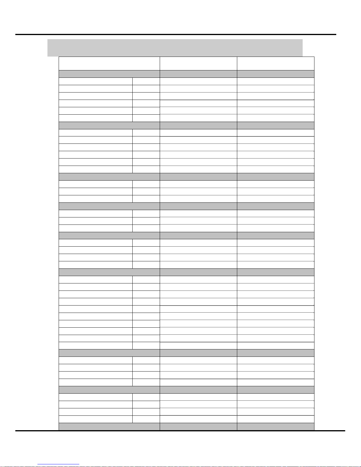
2 Specification
Model
MPM1-10CEN1-BB6
MPM1-10CRN1-BB6
MPM1-10EEN1-BB6
MPM1-10ERN1-BB6
Nameplate marking
Power supply Ph-V-Hz
1φ,115V~,60Hz 1φ,115V~,60Hz
Cooling Capacity1 Btu/h
10000 10000
Cooling Power consumption1 W
1133 1133
Cooling Rated current1 A
10.0 10.0
Cooling EER2 Btu/W·h
8.9 8.9
Electrical heater W
------ 1465
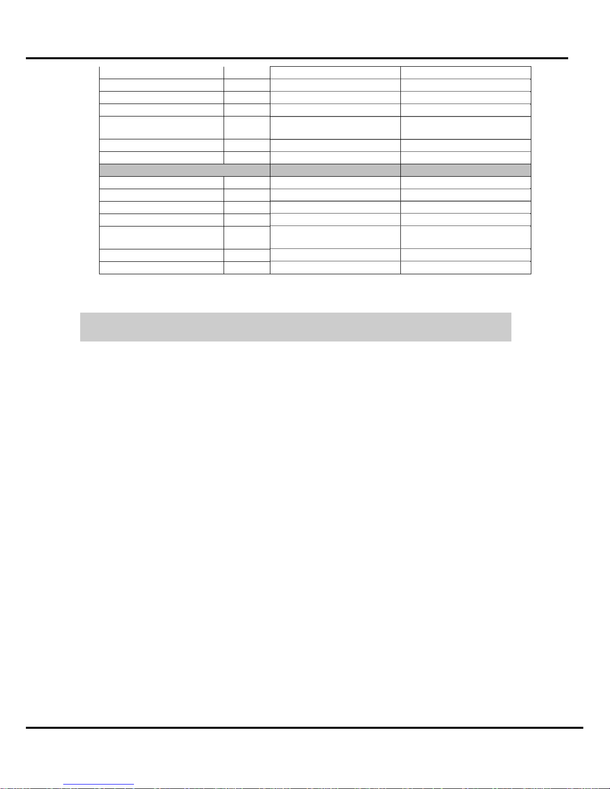
System data
Refrigerant type oz
R22/580 R22/580
Design pressure (Hi/Lo) Psig
2.8 2.8
Moisture Removal Pint/h
3.2 3.2
Water tank volume Pint inner water tank 4L inner water tank 4L
Indoor air flow (Hi/Mi/Lo) m3/h
480/410/360 480/410/360
Noise level (Hi/Mi/Lo) dB(A)
52/50/48 52/50/48
Dimension & Weight
Dimension (W*H*D) mm
480×836×385 480×836×385
Packing (W*H*D) mm
725×875×460 725×875×460
Net/Gross weight
Kg 40/52 40/52
Applicable ambient
Operation temp ℃
17-30 17-30
Ambient temp ℃
10-35 ≤35
Application area m2
14-21 14-21
Water Pump 1 and 2
Current
mA 40 40
Input
W 7 7
Water flow
ml/min 1500 1500
Height lift
m 0.9 0.9
Compressor
Model
EH135X1CY-1DZDU2 EH135X1CY-1DZDU2
Type
Rotary Rotary
Brand
GMCC GMCC
Capacity W
2820 2820
Input W
925 925
Rated current(RLA) A
8.2 8.2
Locked rotor Amp(LRA) A
45.9 45.9
Thermal protector
B440-135-141E B440-135-141E
Capacitor uF
45uF/ 250V 45uF/ 250V
Refrigerant oil cc
400 400
Fan Motor1
Model
YDK62-4AS YDK62-4AS
Input W
145/126/64 145/126/64
Capacitor uF
15uF/250V 15uF/250V
Speed(hi/mi/lo) r/min
1125/1015/630 1125/1015/630
Fan Motor2
Model
YDK65-4AS YDK65-4AS
Input W
114/106/95/83 114/106/95/83
Capacitor uF
15uF/250V 15uF/250V
Speed(hi/mi/lo) r/min
1190/1145/1075/980 1190/1145/1075/980
Evap.
Page 6
Outer dimension
4
a. Number of rows
2 2
b. Tube pitch(a)x row pitch(b) mm
21X13.37 21X13.37
c. Fin spacing mm
1.5 1.5
d. Fin type (code)
Hydrophilic aluminum Hydrophilic aluminum
etude outside diamante type mm
Ф7×0.25×0.18,
inner groove tube
Ф7×0.25×0.18,
inner groove tube
facial length x height x width mm
372x294x26.74 372x294x26.74
g. Number of circuits
2 2
Cond.
a. Number of rows
2 2
b. Tube pitch(a)x row pitch(b) mm
21X13.37 21X13.37
c. Fin spacing mm
1.3 1.3
d. Fin type (code)
Hydrophilic aluminum Hydrophilic aluminum
e. Tube outside dia. and type mm
Ф7×0.25×0.18,
inner groove tube
Ф7×0.25×0.18,
inner groove tube
f. Coil length x height x width mm
758x294x13.37+716x294x13.37 758x294x13.37+716x294x13.37
g. Number of circuits
2 2
1 Cooling capacity estimated using room balance at 27°C db and 19°C wb
2 Cooling EER estimated using room balance at 35°C db and 24°C wb
Page 7
Outer dimension
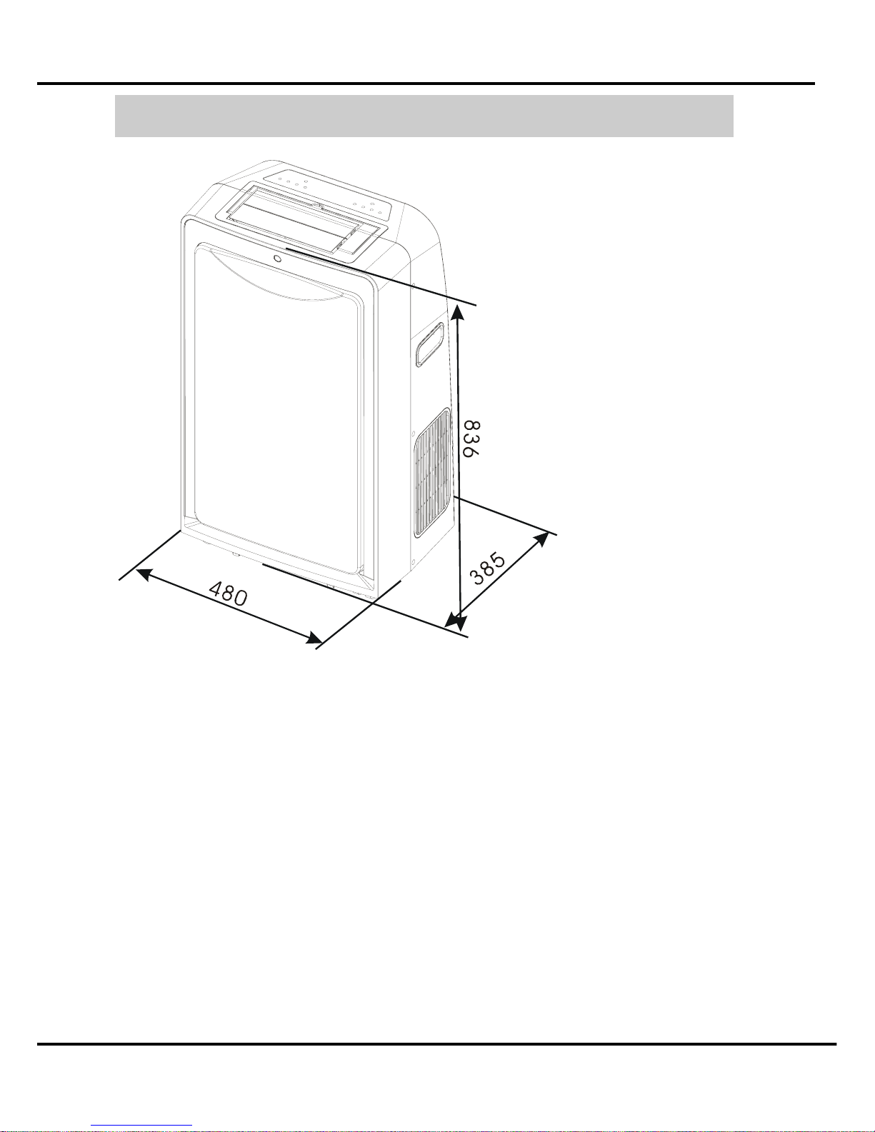
5
3 Out dimension
Page 8
External view, part, display
6
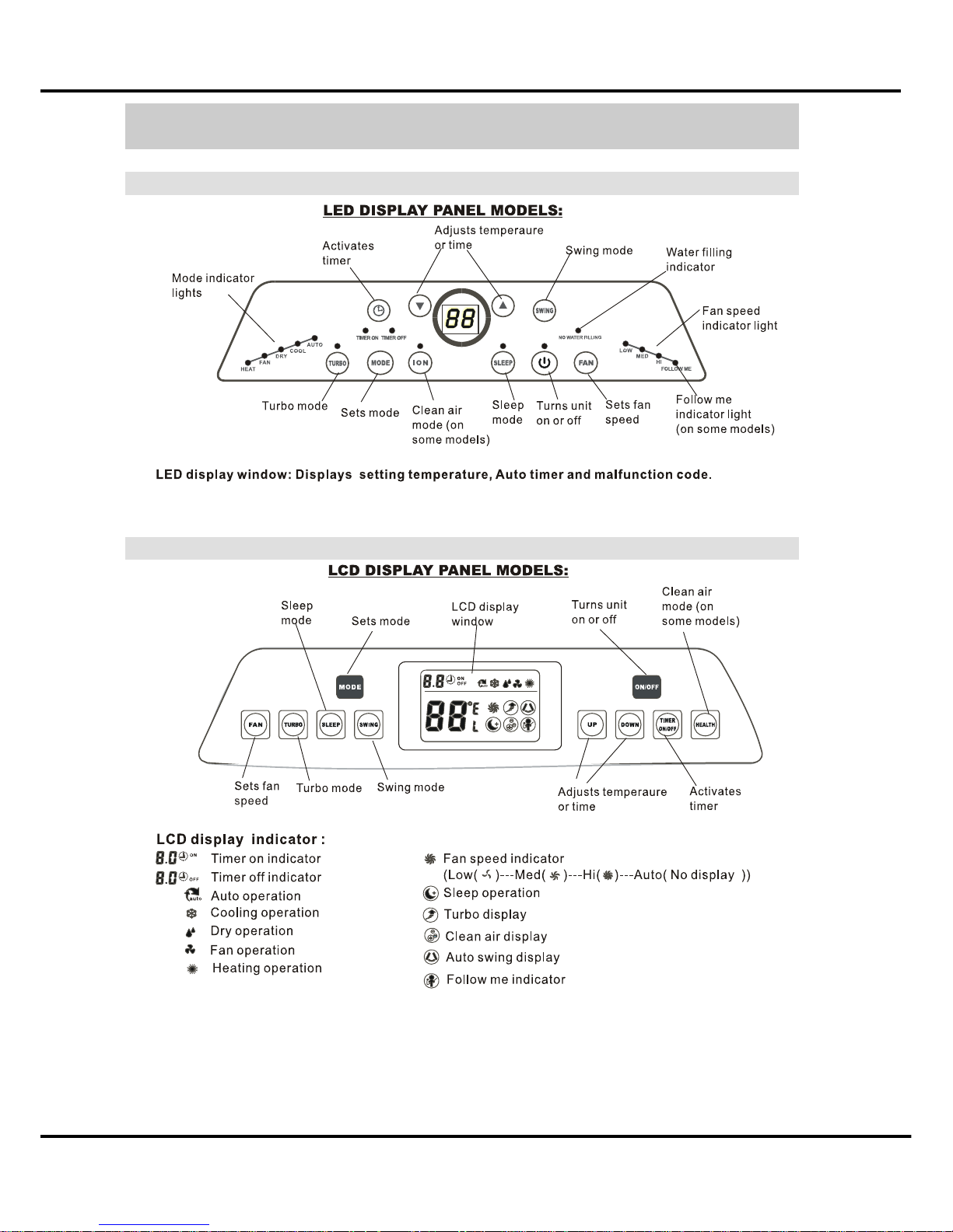
4 Display
4.1 LED display
4.2 LCD display
Page 9
Refrigerant cycle diagram
7
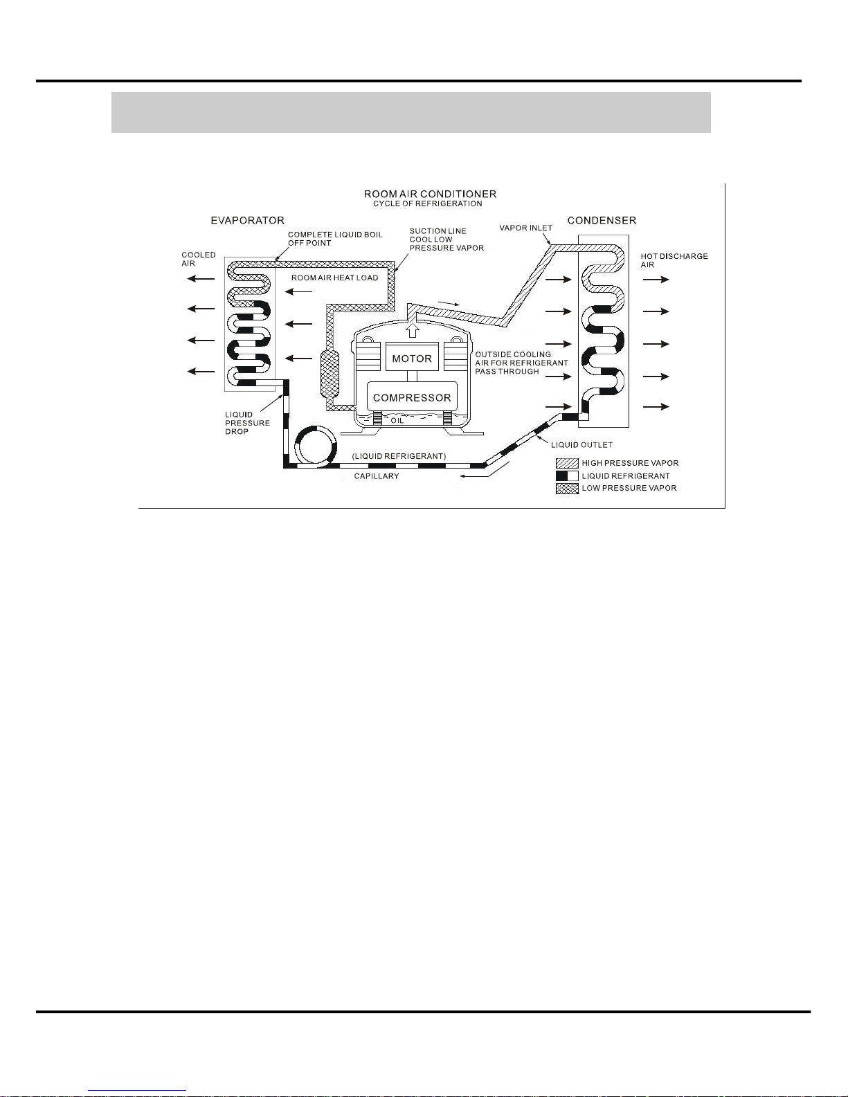
5 Refrigerant cycle diagram
The figure below is a brief description of the important components and their function in what
is called the refrigeration system
Page 10

Installation detail
8
6 PCB drawing & wiring diagram
6.1 10K Model
The below picture is fit for:
MPM1-10CEN1-BB6, MPM1-10CRN1-BB6, MPM1-10EEN1-BB6, MPM1-10ERN1-BB6
Page 11
Installation detail
9
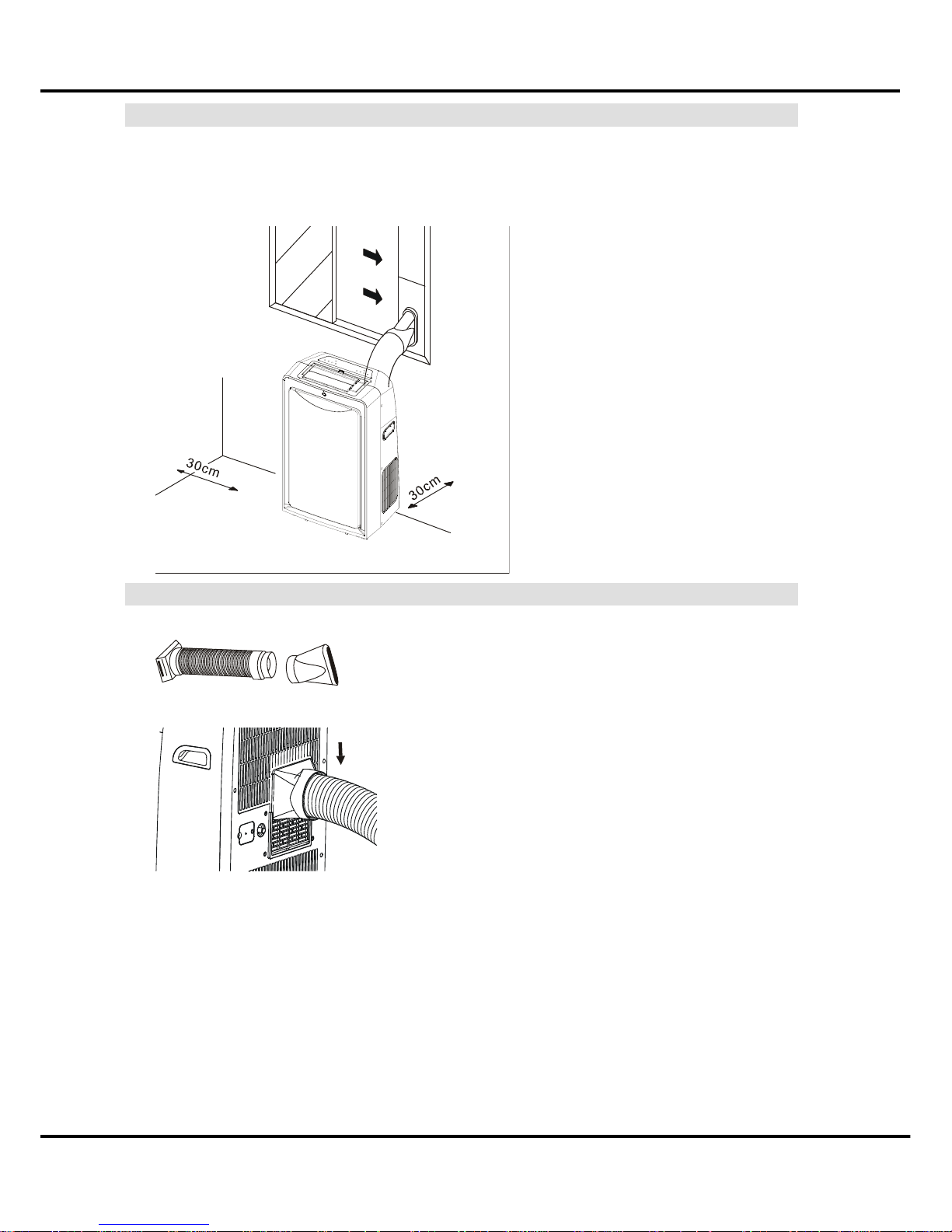
6.2 Position requirement for installation
Installation must be in a flat and spacious location where the air outlets will not be covered up.
A minimum clearance of 30cm from a wall or other obstacles should be kept. The appliance
shall not be used in the washroom. The plug shall accessible after appliance is positioned.
Wiring shall be done according to National rules. Please see the picture show as below.
6.3 Preparation work
First of all, prepare the exhaust hose as the below picture show to you.
Second, connect the exhaust hose with unit, like the blow picture.
After this two steps, please make sure the exhaust hose’s connect is OK.
Page 12

Installation detail
10
6.4 Installation in a double-hung sash windows
6.4.1 Cut the foam seal (adhesive type) to the proper length and attach it to the window stool.
6.4.2 Attach the window panel to the window stool.
Adjust the length of the window panel according to the width of window, short the adjustable
panel if the width of window is less than 26”.
Open the window sash and place the window panel on the window stool.
Secure the window panel to the window stool with 2 screws.
6.4.3 Cut the foam seal (adhesive type) to the proper length attach it on the top of window.
Show as below picture.
6.4.4 Close the window sash securely against the window.
6.4.5 Cut the foam seal to an appropriate length and sealing the open gap between the top
window sash and outer window sash. Show as below picture.
Page 13

Installation detail
11
6.5 Installation in a sliding sash windows
6.5.1 Cut the foam seal to a proper length and adhesive to the window frame.
6.5.2 Attach the window panel to the window stool.
Adjust the length of the sliding window panel according to the width of window, short the
adjustable panel if the width of window is less than 26”.
Open the sliding sash and place the window panel on the window stool.
Secure the sliding window panel to the window stool with 2 screws.
6.5.3 Cut the foam seal (adhesive type) to the proper length attach it on the top of window.
Show as below picture.
Page 14

Installation detail
12
6.5.4 Close the sliding sash securely against the window.
6.5.5 Cut the foam seal to an appropriate length and sealing the open gap between the top
window sash and outer window sash. Show as below picture.
6.6 Permanent installation
6.6.1 Attach one end of the duct to the exhaust air outlet of the mobile air conditioner.
According to the arrow direction, push it downwards, be sure to fix thoroughly.
6.6.2 Install the adaptor A onto the wall by using 4 expansion plugs and screws, be sure to fix
thoroughly.
6.6.3 Attach the other end of the duct to adaptor A.
Page 15

Installation detail
13
6.6.4 Cover the hole using the adaptor cap when not in use.
Page 16

Feature
14
7 Feature
LED display (LCD optional)
360
0
air out grille
Flat plane design
Sliver spray
8 meters remote controller
Turbo cooling function
Flexible air exhaust
Advanced shower system
24 hour on/off
Cooling
Dry
Fan only
No water tank design
Page 17

Electronic function
15
8 Electronic function
8.1 Terms and definitions
TA: Temperature of ambient, (T1).
TC: Temperature of condenser, (T3).
TE: Temperature of evaporator, (T2).
TS: Setting temperature by remoter controller or control plane.
WL1: water level1.
WL2: water level2.
WL3: water level3.
WL4: water level4.
S1: Switch 1.
S2: Switch 2.
S3: Switch 3.
S4: Switch 4.
8.2 Electric part assembly condition that use
8.2.1 Scope of application of voltage of the power:
UL: 97-127 VAC, 60Hz, 1 phase;
CE: 187- 264 VAC, 50Hz, 1 phase;
8.2.2 Working environment: -10’C~+50’C.
8.2.3 The humidity of electric part working environment: RH10%~RH95%.
8.2.4 The electric storage working temperature: -20’C~+70’C.
8.3 PCB working environment.
8.3.1 Tolerance of measure indoor side temperature: ±1’C, the scope of application: 50~99
Fahrenheit degree (+10~+37 Centigrade degree).
8.3.2 Tolerance of measure evaporator temperature: ±1’C, the scope of application: 30~99
Fahrenheit degree (-1~+37 Centigrade degree).
8.3.3 Tolerance of timer: 15 minutes per 24 hours.
8.3.4 The signal receive distance should be more than 8 meters.
8.3.5 EMC, EMI accord with CE authentication demand.
8.3.6 The electric apparatus accords with CE, UL, GB4706.32-1996, GB/T7725-1996
demand safely.
Page 18

Electronic function
16
8.4 Protection function
8.4.1 Time delay safety control (3 minutes).
When the compressor is stopped by the remote controller, it restarts after 3 minutes when the
remote controller is turn ON.
When the setting temperature is reached during cooling operation, the compressor stop and it
will not start for 3 minutes.
If the auto-restart is available, the compressor only needs to delay time and start the machine
in 1 minute.
8.4.2 Anti-freezing protect control
If the temperature of the indoor evaporator falls continuously below 2’C (65’F) for 3 minutes or
more, the compressor turn off to protect the indoor evaporator from freezing.
Compressor will restart again when the indoor evaporator temperature rises to 10’C.
See the below graph:
At the anti-freezing control, the pump 1 and pump 2 maintain the origin state. If the mode
change to Fan or Heat mode, the time delays safety control cancel. If turn back to cooling
mode, timing again.
8.4.3 Overheat protect
At cooling or dry mode, the unit state is ON.
8.4.3.1 If the water level is being the WL1 above, and the T3≥63’C for 3 seconds continuously.
The inner fan motor will be force to low wind and outer fan motor will be force to high
wind. If the T3≤57’C, the unit fan motor back to the origin state that setting by customer.
See the below graph:
Note: The over-heat protect have priority to the WL protect.
3min
2’C
35.6’F
10’C
50’F
T2
Comp. off
Recovery
Page 19

Electronic function
17
8.4.4 Water full protection.
There are four switches on the base-pan water tank. S1, S2, S3, S4.
As you see the below graph.
If the water level exceed WL1, S1 activity, the Pump 1 that in charge of shower system start to
work. The fan motor maintains the origin state. After 1 hour, if the water level still exceed WL1,
but not exceed WL2. The outer fan motor will turn to low fan. If the water level drop below the
WL1, the pump 1 will have 2 minutes delay to shut down.
If the water level continues rise and reaching WL2, S2 activity, the outer fan turn to the low fan,
after 20 minutes later, the pump 2 that in charge of drain water out start to work, drain the
water to the auxiliary tank. If the water level drops below WL1, the pump 2 stop and the outer
fan motor maintain the low fan.
At the above 2 steps, if the unit turn from cooling mode to heating and dry mode, the pump 1
and pump 2 stop immediately.
If the water level meets to the WL4, S4 activity, the display will show the P1 protect. All of the
loads will into the status of sleep, the unit will back to the origin setting mode unless the water
level drops down. The TURBO button is available at P1 protection.
If the water level meets to the WL3, S3 activity, the display will show the P2 protect, at this
status, the unit will shut-down. After re-power and drain out water by base-pan drainage hose,
the unit could be back to the origin status.
WL3
WL4
WL2
WL1
Base pan
Auxiliary tank
Page 20

Electronic function
18
8.4.5 Malfunction
8.5 Cooling operation
8.5.1 At cooling mode, the range of work is 17’C~30’C (62’F ~88’F).
8.5.2 The fan setting: AUTO, low, middle, high, turbo.
8.5.3 The action of compressor at cooling mode:
The inner fan motor will start when the unit into cooling mode, the outer fan motor work status
needs according to the TA-TS and the water level.
If the water level is exceed WL1 and below WL3 or WL4, the outer fan motor start at once,
otherwise, the fan motor work status according to the compressor status.
If the TA-TS>1, the outer fan motor on and the compressor will start after 13 s.
If the TA<TS, the compressor off and the fan motor will stop after 13 s.
See the below graph.
8.5.4 The compressor status was judged by TA and TS, but the compressor will work 5
minutes at least for each start up. If the TS changed during this period, judge TS and
TA at once, the 5 minutes wait will be cancel.
8.5.5 If shutdown unit at cooling mode, the inner and outer fan will stop after 15 second. If
turn from cooling mode to heating mode or dry mode, the outer fan motor will stop after
15 s.
8.5.6 Auto fan at cooling mode.
The fan motor speed is decided by the TA and TS different.
If the inner fan is at low wind and TA-TS≥1'C, the fan motor turn to middle fan and the
continue running 1 minute at least.
If the inner fan is at middle wind and TA-TS≥1'C, the fan motor turn to high fan and continue
running 1 minute at lease.
If the inner fan is at middle wind and TA=TS, the fan motor maintain the middle wind and
continue running 1 minute at lease.
LCD or LED display Malfunction
P2 Water full protection.
P1 Drainage protection.
E3 T3 sensor malfunction.
E2 T2 sensor malfunction.
E1 T1 sensor malfunction.
Page 21

Electronic function
19
If the inner fan is at middle wind and TA-TS≥-1'C, the fan motor turn to low fan and continue
running 1 minute at lease.
8.5.7 The ionizer and timer are available at cooling mode.
8.6 Auto mode
8.6.1 At auto mode, the range of work is 17’C~30’C (62’F ~88’F).
8.6.2 At auto mode, the inner fan speed is only judge by the TA and TS, people can’t set it.
8.6.3 At auto mode, the air conditioner automatically selects one of following operation
modes: Cooling, Heating, Fan mode according to the temperature different between
TA and TS.
8.7 Fan mode
8.7.1 At the fan mode, the inner fan motor always on and compressor and outer fan motor off.
8.7.2 The display shows the ambient temperature at fan mode, the temperature can not be
adjusted.
8.7.3 The fan speed can by changed at fan mode; the auto fan mode function is same as the
fan speed control on auto mode at 24’c.
8.7.4 The ionizer and timer are available at fan mode.
8.7.5
8.8 Dry mode
8.8.1 At dry mode, the setting temperature can not be changed. The display shows the
ambient temperature.
8.8.2 The action of compressor at Dry mode.
8.8.3 At the dry mode, the fan speed can not be adjusted. The inner fan motor is at low fan
and the outer fan motor is at middle fan.
8.8.4 At the dry mode, the ionizer and timer are available.
8.8.5 If shut-down the unit, the compressor will shut-down at once, the inner and outer fan
will have 15s delay for shut down. If turn the unit to the fan or heating mode, the
compressor shut-down at once, the outer fan will have 15s delay only.
Page 22

Electronic function
20
8.9 Heating mode
8.9.1
8.9.2 At heating mode, the setting temperature range is 17’C~30’C. (62’F~88’F)
8.9.3 At heating mode, the action of the electric heater:
8.9.4 The inner fan speed can by select at heating mode----Auto, low, middle, and high. The
outer fan is off and compressor is off at heating mode.
8.9.5 Auto wind at heating mode.
8.9.5.1 The fan motor is decided by the temperature different between TA and TS.
8.9.5.2 If the fan motor is at low speed, and TA-TS≤-1’C, the fan motor turn to middle fan and
continue running 1 minute at least.
8.9.5.3 If the fan motor is at middle speed, and TA≤TS-1°C, the fan motor turn to high fan and
continue running 1 minute at least.
8.9.5.4 If the fan motor is at middle speed, and TA=TS, the fan motor maintain the middle fan
and continue running 1 minute at least.
8.9.5.5 If the fan motor is at middle speed, and TA≥TS+1°C, the fan motor turn to low fan and
continue running 1 minute at least.
8.9.6 The ionizer and timer are available at heating mode.
Page 23

Basic test procedure
21
9 Basic test procedure
9.1 Defective compressor
Compressors are single phase, 115 or 230/208 volt, depending on the model unit. All
compressor motors are permanent split capacitor type using only a running capacitor across
the start and run terminal.
All compressors are internally spring mounted and externally mounted on rubber isolators.
9.1.1 Compressor wiring test
Remove compressor terminal box cover and disconnect wires from terminals. Using an
ohmmeter, check continuity across the following:
Terminal "C" and "S" - no continuity
- Open winding - replace compressor.
Terminal "C" and "R" - no continuity
- Open winding - replace compressor.
Terminal "R" and "S" - no continuity
- Open winding - replace compressor.
9.1.2 Ground test
Use an ohmmeter set on its highest scale. Touch one lead to the compressor body (clean point
of contact as a good connection is a must) and the other probe in turn to each compressor
terminal (see Figure 2.) If a reading is obtained, the compressor is grounded and must be
replaced.
9.1.3 Checking the compressor efficiency
The reason for compressor inefficiency is normally due to broken or damaged suction and/or
discharge valves, reducing the ability of the compressor to pump refrigerant gas.
This condition can be checked as follows:
1. Install a piercing valve on the suction and discharge or liquid process tube.
2. Attach gauges to the high and low sides of the system.
3. Start the system and run a “cooling or heating performance test.”
Page 24

Basic test procedure
22
If test shows:
A. Below normal high side pressure.
B. Above normal low side pressure.
C. Low temperature difference across coil.
The compressor valves are faulty - replace the compressor.
9.1.4 Terminal overload (external)
Some compressors are equipped with an external overload which is located in the compressor
terminal box adjacent to the compressor body the overload is wired in series with the common
motor terminal. The overload senses both major amperage and compressor temperature. High
motor temperature or amperage heats the disc causing it to open and break the circuit to the
common motor terminal.
Heat generated within the compressor shell is usually due to:
High amperage.
Low refrigerant charge.
Frequent recycling.
Dirty condenser.
9.1.5 Terminal overload – Test (compressor external type)
1. Remove overload.
2. Allow time for overload to reset before attempting to test.
3. Apply ohmmeter probes to terminals on overload wires. There should be continuity
through the overload.
9.1.6 Terminal overload (internal)
Some model compressors are equipped with an internal overload. The overload is embedded
in the motor windings to sense the winding temperature and/or current draw. The overload is
connected in series with the common motor terminal.
Should the internal temperature and/or current draw become excessive; the contacts in the
overload will open, turning off the compressor? The overload will automatically reset, but may
require several hours before the heat is dissipated.
9.1.7 Checking the internal overload
With no power to unit, remove the leads from the compressor terminals.
Using an ohmmeter, test continuity between terminals C-S and C-R. If not continuous, the
compressor overload is open and the compressor must be replaced.
9.2 Sealed refrigeration system repairs
9.2.1 Equipment require
Voltmeter
Ammeter
Ohmmeter
E.P.A. Approved Refrigerant Recovery System.
Vacuum Pump (capable of 200 microns or less vacuum.)
Page 25

Basic test procedure
23
Acetylene Welder
Electronic Halogen Leak Detector (G.E. Type H-6 or equivalent.)
Accurate refrigerant charge measuring device such as:
a. Balance Scales - 1/2 oz. accuracy
b. Charging Board - 1/2 oz. accuracy
High Pressure Gauge - (0 - 400 lbs.)
Low Pressure Gauge - (30 - 150 lbs.)
Vacuum Gauge - (0 - 1000 microns)
9.2.2 Equipment must be capable of:
Recovery CFC's as low as 5%.
Evacuation from both the high side and low side of the system simultaneously.
Introducing refrigerant charge into high side of the system.
Accurately weighing the refrigerant charge actually introduced into the system.
Facilities for flowing nitrogen through refrigeration tubing during all brazing processes.
9.2.3 Hermetic compressor replacement.
The following procedure applies when replacing components in the sealed refrigeration circuit
or repairing refrigerant leaks. (Include Compressor, condenser, evaporator, capillary tube,
refrigerant leaks, etc.)
Recover the refrigerant from the system at the process tube located on the high side of
the system by installing a line tap on the process tube. Apply gauge from process tube to EPA
approved gauges from process tube to EPA approved recovery system. Recover CFCs in system
to at least 5%.
Cut the process tube below pinch off on the suction side of the compressor.
Connect the line from the nitrogen tank to the suction process tube.
Drift dry nitrogen through the system and unsolder the more distant connection first.
(Filter drier, high side process tube, etc.)
Replace inoperative component, and always install a new filter drier. Drift dry nitrogen
through the system when making these connections.
Pressurize system to 30 PSIG with proper refrigerant and boost refrigerant pressure to
150 PSIG with dry nitrogen.
Leak test complete system with electric halogen leak detector, correcting any leaks found.
Reduce the system to zero gauge pressure.
Connect vacuum pump to high side and low side of system with deep vacuum hoses, or
copper tubing. (Do not use regular hoses.)
Evacuate system to maximum absolute holding pressure of 200 microns or less. NOTE:
This process can be speeded up by use of heat lamps, or by breaking the vacuum with
refrigerant or dry nitrogen at 5,000 microns. Pressure system to 5 PSIG and leave in system a
minimum of 10 minutes. Recover refrigerant, and proceed with evacuation of a pressure of
200 microns or a minimum of 10%.
Break vacuum by charging system from the high side with the correct amount of
refrigerant specified. This will prevent boiling the oil out of the crankcase.
NOTE: If the entire charge will not enter the high side, allow the remainder to enter the low side
in small increments while operating the unit.
Page 26

Basic test procedure
24
Restart unit several times after allowing pressures to stabilize. Pinch off process tubes,
cut and solder the ends. Remove pinch off tool, and leak check the process tube ends.
9.2.4 Special procedure in the case of compressor motor burnout.
Recover all refrigerant and oil from the system.
Remove compressor, capillary tube and filter drier from the system.
Flush evaporator condenser and all connecting tubing with dry nitrogen or equivalent, to
remove all contamination from system. Inspect suction and discharge line for carbon deposits.
Remove and clean if necessary.
Reassemble the system, including new drier strainer and capillary tube.
Proceed with processing as outlined under hermetic component replacement.
9.2.5 Rotary compressor special troubleshooting and service
Basically, troubleshooting and servicing rotary compressors is the same as on the
reciprocating compressor with only a few exceptions.
Because of the spinning motion of the rotary, the mounts are critical. If vibration is
present, check the mounts carefully.
The electrical terminals on the rotary are in a different order than the reciprocating
compressors. The terminal markings are on the cover gasket. Use your wiring diagram to
insure correct connections.
9.2.6 Refrigerant charge
The refrigerant charge is extremely critical. It must be measured charge carefully - as
exact as possible to the nameplate charge.
The correct method for charging the rotary is to introduce liquid refrigerant into the high
side of the system with the unit off. Then start compressor and enter the balance of the
charge, gas only, into the low side.
The introduction of liquid into the low side, without the use of a capillary tube, will cause
damage to the discharge valve of the rotary compressor.
NOTE: All inoperative compressors returned to Friedrich must have all lines properly plugged
with the plugs from the replacement compressor.
9.3 Fan motor
A single phase permanent split capacitor motor is used to drive the evaporator blower and
condenser fan. A self-resetting overload is located inside the motor to protect against high
temperature and high amperage conditions.
9.3.1 Fan motor test
Determine that capacitor is serviceable.
Disconnect fan motor wires from fan speed switch or system switch.
Apply "live" test cord probes on black wire and common terminal of capacitor. Motor
should run at high speed.
Apply "live" test cord probes on red wire and common terminal of capacitor. Motor should
run at low speed.
Page 27
Basic test procedure
25
Apply "live" test cord probes on each of the remaining wires from the speed switch or
system switch to test intermediate speeds.
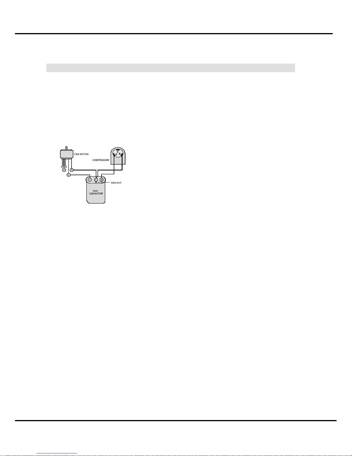
9.4 Capacitor
A run capacitor is wired across the auxiliary and main winding of a single phase permanent
split capacitor motor such as the compressor and fan motor. A single capacitor can be used for
each motor or a dual rated capacitor can be used for both.
The capacitor's primary function is to reduce the line current while greatly improving the torque
characteristics of a motor. The capacitor also reduces the line current to the motor by
improving the power factor of the load. Run capacitor hook-up line side of the capacitor is
marked with a red dot and is wired to the line side of the circuit
9.4.1 Capacitor test
Remove capacitor from unit.
Check for visual damage such as bulges, cracks, or leaks.
For dual rated, apply an ohmmeter lead to common (C) terminal and the other probe to
the compressor (HERM) terminal. A satisfactory capacitor will cause a deflection on the pointer,
and then gradually move back to infinity.
Reverse the leads of the probe and momentarily touch the capacitor terminals. The
deflection of the pointer should be two times that of the first check if the capacitor is good.
Repeat steps 3 and 4 to check fan motor capacitor.
NOTE: A shorted capacitor will indicate a low resistance and the pointer will move to the "0"
end of the scale and remain there as long as the probes are connected.
An open capacitor will show no movement of the pointer when placed across the terminals of
the capacitor.
Page 28

Characteristic of temperature sensor
26
10 Characteristic of temperature sensor
Temp.℃
Resistance
KΩ
Temp.℃
Resistance
KΩ
Temp.℃
Resistance
KΩ
-10 62.2756 17 14.6181 44 4.3874
-9 58.7079 18 13.918 45 4.2126
-8 56.3694 19 13.2631 46 4.0459
-7 52.2438 20 12.6431 47 3.8867
-6 49.3161 21 12.0561 48 3.7348
-5 46.5725 22 11.5 49 3.5896
-4 44 23 10.9731 50 3.451
-3 41.5878 24 10.4736 51 3.3185
-2 39.8239 25 10 52 3.1918
-1 37.1988 26 9.5507 53 3.0707
0 35.2024 27 9.1245 54 2.959
1 33.3269 28 8.7198 55 2.8442
2 31.5635 29 8.3357 56 2.7382
3 29.9058 30 7.9708 57 2.6368
4 28.3459 31 7.6241 58 2.5397
5 26.8778 32 7.2946 59 2.4468
6 25.4954 33 6.9814 60 2.3577
7 24.1932 34 6.6835 61 2.2725
8 22.5662 35 6.4002 62 2.1907
9 21.8094 36 6.1306 63 2.1124
10 20.7184 37 5.8736 64 2.0373
11 19.6891 38 5.6296 65 1.9653
12 18.7177 39 5.3969 66 1.8963
13 17.8005 40 5.1752 67 1.83
14 16.9341 41 4.9639 68 1.7665
15 16.1156 42 4.7625 69 1.7055
16 15.3418 43 4.5705 70 1.6469
Page 29

Trouble shooting
27
11 Trouble shooting
PROBLEM POSSIBLE CAUSE REMEDY
No power display
on panel or any
one of the buttons
failure.
Power failure
Check the power supplier if the power supplier is supplied
to the unit. Check the power cord and correct if damaged.
Transformer (Discharge
transformer before
testing)
Check resistance between the two input/output lines on
transformer. Replace the transformer if either of the
input/output is open or the transformer is damaged.
Display board or main
PCB failure
Check the voltage on display board. Replace the display
board if it is +5V else replace the main PCB.
Remote control
failure.
Battery failure
Check the voltage of battery. Replace batteries if the
voltage is lower than 2.3V.
Fan motor runs
intermittently
Cycles on overload.
Check voltage. Call an electrician if not within limits.
Test capacitor.
Replace if not within +/-10% of manufacture's rating.
Check bearings. Replace the motor if the blower wheel
cannot rotate freely.
Pay attention to any change from high speed to low speed.
Replace the motor if the speed does not change.
Compressor
stops instantly
after startup.
Refrigerant
The amount of the refrigerant is too much, making the
compressor load too big. Recycle and recharge the
refrigerant after checking for the reason.
Compressor
The compressor is blocked inside. Replace after checking
for the reason.
Fan motor will not
run.
No power Check voltage at electrical outlet. Correct if none.
Water alarm Check and correct if water alarm happens.
Power supply cord
Check voltage at the power cord terminal on Main PCB.
Replace the power cord if none.
Transformer (Discharge
transformer before
testing)
Check resistance between the two input/output lines on
transformer. Replace the transformer if either of the
input/output is open or the transformer is damaged.
Wire disconnected or
connection loose
Connect wire. Refer to wiring diagram for terminal
identification. Repair or replace loose terminal.
Main PCB failure
Select fan speed and Check the voltage on main PCB.
Replace the main PCB if no voltage in anyone.
Capacitor (Discharge
capacitor before testing)
Test capacitor.
Replace if not within +/-10% of manufacture's rating.
Replace if shorted, open or damaged.
Will not rotate
Fan blower hitting scroll. Realign assembly.
Check fan motor bearings. Replace the motor if motor shaft
do not rotate.
Fan motor noise. Fan blower
Replace the fan blower if cracked, out of balance, or
partially missing.
Page 30

Trouble shooting
28
Loose screws Tighten them.
Worn bearings
Replace the motor if knocking sounds continue when
running or loose, or the motor hums or noise appears to be
internal while running.
Compressor will
not run while fan
motor runs.
Voltage Check voltage. Call Supply Authority if not within limits.
Wiring
Check the wire connections, if loose, repair or replace the
terminal. If wires are off, refer to wiring diagram for
identification, and replace. Check wire locations. If not per
wiring diagram, correct.
Main PCB failure Check voltage of main PCB. Replace the main PCB if open.
Capacitor (Discharge
capacitor before testing)
Check the capacitor.
Replace if not within +/-10% of manufacturers rating.
Replace if shorted, open, or damaged.
Room temp sensor
Check the temperature setting if not at the coolest (in
cooling mode) or the warmest (in heating mode). Set it if
not.
Compressor
Check the compressor for open circuit or ground. If open or
grounded, replace the compressor.
Excessive noise. Copper tubing
Remove the cabinet and carefully rearrange tubing not to
contact cabinet, compressor, shroud and barrier.
Water full alarm
Water tank full Check and pour if the water tank is full.
Water depth sensor if
failure
Check and replace if failure.
Water pump failure Check and replace if the pump if failure.
Water depth is over load
in chassis
Check and drainage the water in the chassis by open the
drainage hose on the chassis.
Water depth sensing
structure
Check and replace or realign if the structure is failure.
Cooling or
heating feels not
good
Air filter Clean or replace if restricted.
Air discharge pipe
Realign and assemble if the installation of the air
discharging pipe failure. Replace if damaged.
Unit undersized
Determine if the unit is properly sized for the area to be
cooled or heated.
Condenser and
Evaporator
Clean or replace if restricted.
Water shower failure
Check the structure of water showering system and clean if
blocked.
Fan motor
Check the fan capacitor and replace if not within +/-10% of
manufactures rating.
Air flow
Clean or remove if any barrier is found to block the
inlet/outlet wind flow of the unit.
Less refrigerant
Check the tubes for reasons of leakage. Recycle the
refrigerant, correct the leakage points and recharge.
Page 31

Trouble shooting
29
Capillary tube
Regulate the flow if capillary tube and make the
evaporating temperature appropriate if the evaporator is
frosted. Replace if blocked. Repair joint if leaking.
Compressor
The inlet and outlet valve of the compressor is damaged,
making the low pressure connected with the high pressure.
The refrigerating system can not produce high pressure
and low pressure. Replace the compressor after checking
for the reason.
Heat sources Reduce if too many.
No cooling or
heating.
No power Check the voltage. Call an electrician if no within the limit.
Wiring Check the terminals. Repair and correct if loose.
Temperature setting Check and adjust the temperature setting.
Mode setting Check and adjust the mode setting.
Compressor
Check and replace if the compressor, the over-load
protector or wiring is broken.
Electric heater failure Check and replace if the heater is damaged.
Over heat fuse failure Check and replace if the fuse is damaged.
Main PCB
Check the voltage of main PCB. Replace the main PCB
when the unit failure in heating mode.
The unit starts
and stops
frequently.
Power supply
The input power supply voltage is too low. Call an
electrician if not within limits.
Main PCB
Check and replace the main PCB if the compressor relay
on PCB is shorted or damaged.
Room temperature
When the room temperature is too high, the compressor
will protect.
Page 32

Exploded view & spare-part
30
12 Exploded view & spare-part
12.1 Exploded view of unit
Page 33

Exploded view & spare-part
31
12.2 Exploded view of accessory part
Page 34

Exploded view & spare-part
32
12.3 Spare part list
Model name
UL-KC30Y1-M1(B6)(MPM1-10CR-BB6)
Compressor
EH135X1CY-1DZDU2(Toshiba)
Fan motor (inner)
YDK62-4AS
Fan motor (outer)
YDK65-4AS
NO.
Name
Quantity
Factory code
1 E. part installation plane assembly 1 2332549085
1.1 Installation plane assembly 1 2122549014
1.2 Comp. capacitor 1 2240109021
1.3 Holder of capacitor 1 2120010010
2 Chassis assembly 1 2112549128
2.1 Base-pan 1 2112549107
2.2 Universal wheel 4 2272500002
2.3 Switch 1 1 2230180152
2.4 Switch 2 1 2230180153
2.5 Switch 3 1 2230180154
2.6 Switch 4 1 2230180155
2.7 Pump 1 1 2240060019
2.8 Pump 2 1 2240060020
2.9 Pump fix plane 1 2122549022
2.10 Comp. base-pan 1 2122549017
2.11 Rubber 1 2272509015
2.12 Pump 1 drainage tube 1 2112549078
2.13 Pump 2 drainage tube 1 2112549105
3 Left support strip 1 2122549015
4 Rigth support strip 1 2122549016
5 Display seembly 1 2332549078
6 Rear plane 1 2112549124
7 Rigth holder 1 2112549122
8 Power cord cover 1 2112539008
9 Valve of add water 1 2112549121
10 Air filter 1 2112549119
11 Inner grille 1 2112549120
12 Left holder 1 2112549123
13 Exhaust net protect 1 2122549012
14 Exhaust scroll assembly 1 2112549112
15 Exhaust fan 1 2112509517
16 Anti-water cover 1 2272549004
17 Fan motor (outer) 1 2240042253
18 Watershed cover 1
2112549103
19 Exhaust scroll cover 1 2112549100
Page 35

Exploded view & spare-part
33
20 Drainage tube 1 2112549129
21 E. part aseembly 1 2332539006
21.1 E. part box 1 2112549075
21.2 Main PCB assembly 1 2132549020
21.3 Cpacitor 1 2240110105
21.4 Transformer 1 2230090122
21.5 Main connect PCB 1 2132549019
22 Cpacitor 1 2240110104
23 Room sensor 1 2230130110
24 Evap. Sensor 1 2242049075
25 Cond. Sensor 1 2244200406
26 Discharge scroll solar halo 1 2112549098
27 Exhaust fan 1 2112509517
28 Air outlet net cover 1 2122549013
29 Discharge scroll 1 2112549097
30 Evap. Assembly 1 2152539004
31 Fan motor (Inner) 1 2240042252
32 Compressor
1 2140062230
33 Cond. Assembly
1 2152539006
34 Air outlet assembly
1 2112549118
34.1 Step motor 1 2240020039
35 Front plane assembly
1 2112549126
35.1 Front plane
1 2112549131
35.2 Front plane broder
1 2112549087
35.3 Receiveor assembly
1 2132549017
35.4 Receiveor cover
1 2112549089
35.5 Front cover
1 2112549130
36 E. box cover 1 2122549020
37 Fixing tie-in for outdoor wind discharge 1 2112508107
38 Outdoor wind discharging pipe 1 2112500013
39 Mid-tie-in for outdoor wind discharge 1 2112509064
40 Air discharger 1 2112509063
41 Window sealing board I 1 2112509001
42 Window sealing board II 1 2112509002
43 Remote control 1 2335509205
 Loading...