

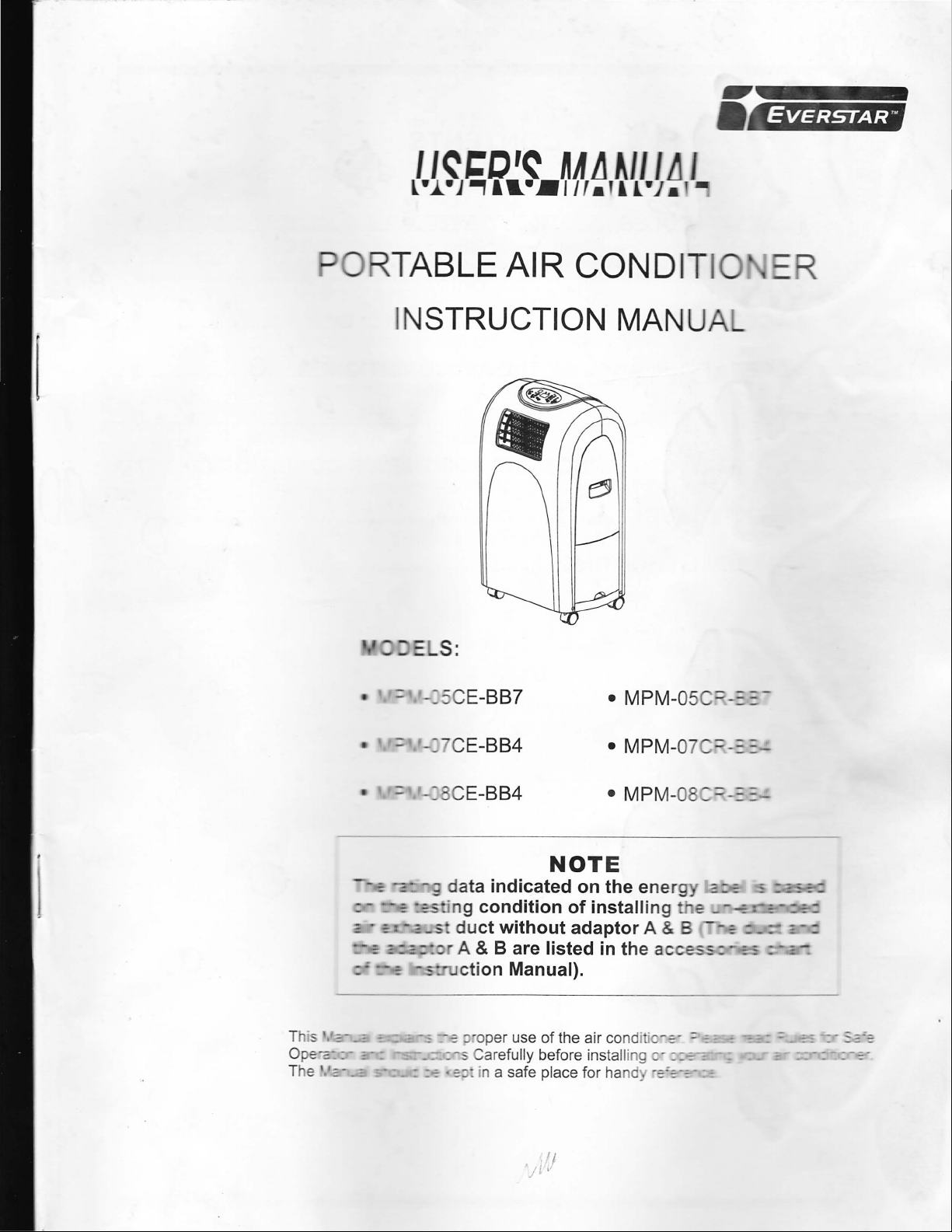
Page 1
~"-111111111111-
EVERSTAR
'·
TABLE
AIR
CONDIT
I
INSTRUCTION MANUA
: -CE-BB7
• MPM-05
C:::
=.::-
- CE-BB4
- CE-BB4
• MPM-0 7 - ::.::-
• MPM-08
-::::
-
NOTE
-91
data
indicated
-
-~'n g
-
-_s
-
_=-:
:
:-=-
condition
duct
without
& B are
A
ction
-s:)
--
• ::J: in a safe place for
Manual}.
oper use
Carefully before installing ": :--:-
'jt
on
of
installing
adaptor
listed
of
the air cond
~j
the
ener
A & B
in the ace
i ·c-
:="
ha
nd:
~~
:: -
~
--:
..,...-.-
-~
=
Page 2
CONTENTS
1.SAFETY RULES ............................................................................. 1
2.NAMES OF PARTS .......................................................................... 2
3.ACCESSORIES ................................................................................ 3
4.0PERATION PANEL OF THE AIR CONDITIONER ........................ 3
5.INSTALLATION ................................................................................ 5
6.0PERATING INSTRUCTIONS FOR THE AIR CONDITIONER ..... 7
7 .MAINTENANCE ............................................................
B.TROUBLE SHOOTING ....................................................................
...................
11
12
Page 3
SAFETY RULES
1.
DO NOT CONNECT THE UNIT TO A DAMAGED OR DEFECTIVE ELECTRICAL
OUTL
ET.
2. DO NOT USE
IN
THE FOLLOW ING LOCATIONS:
- NEXT TO SOURCE OF FIRE.
- AN AREA WHERE OIL IS LIKELY TO SPLASH.
- AN AREA EXPOS ED TO DIRECT SUNLIGHT.
- AN AREA W ERE WATER
IS LIKELY TO SPLASH.
- NEAR A BATH, A SHOWER OR A SWIMMING POOL
-
IN
THE GR EE HOUSE
3.
NEVER INSERT YO R FINGERS OR ANY FOREIGN OBJECTS INTO THE AIR
OUTLET.
4.
ALWAYS STORE THE NIT
TAKE SPECIAL CARE TO WARN CHILDREN OF
UPRIGHT.
THESE
DANGERS .
5. BE SURE TO UNPLUG TH E UNIT BEFORE CLEANING.
6. THE HEATER MUS OT BE LOCATED IMMEDIATELY
OUTLE
T.
7. IF TH E APP LIANCE IS COVERED, THERE IS A RISK OF
BELOW A SOCKET
OVERHEAT.
If the s '
nu
ma
pe
rso I"
:::::
a
.~~f:~
CAUTION
::.2~
~
is dama ged ,
~~
s service agent or a similarly qualified
~::eC:
O
avoid a hazard.
it
must
be
replac
ed
by the
Page 4
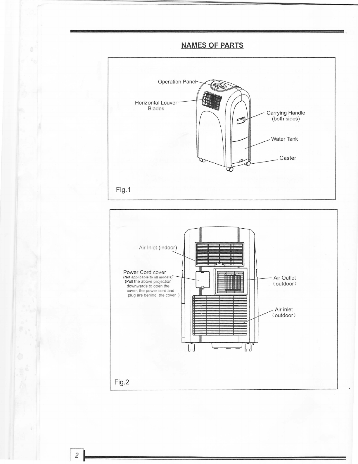
NAMES OF PARTS
Fig.1
Operation
Horizontal Louver
Blades
Ai
r Inlet (indoor)
Pa
Carrying Handle
(both sides)
Water Tank
Caster
(Not
applic
able
(PUll the above projectio n
downwards to open the
er.
the power cord and
cov
plug are beh nd the cover )
Fig.2
to
all I
~1111I1r-
~
Air Outlet
(outdoor)
Air
(outdoor)
inlet
Page 5
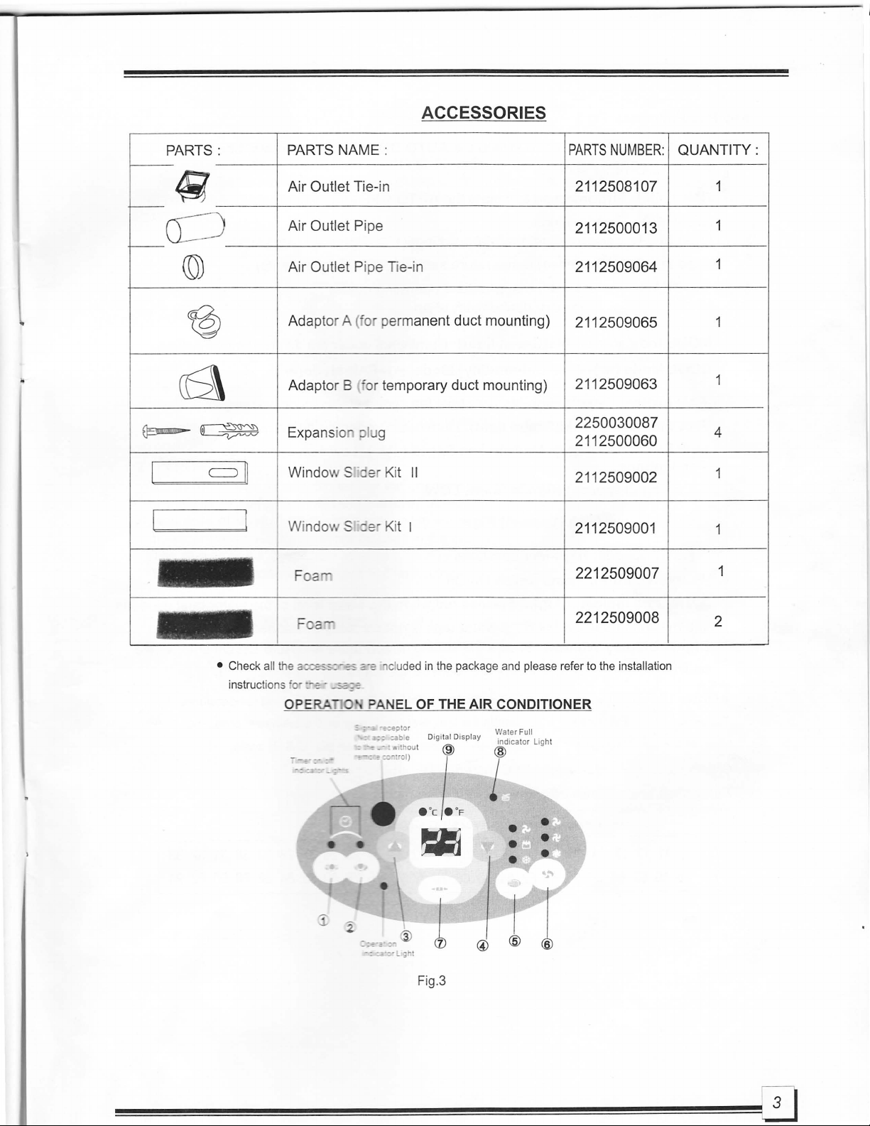
ACCESSORIES
PARTS:
4i
0
(6\
~~
CO)
@)
c=J
PARTS NAME :
Air Outlet Tie-in 2112508107
Air Outlet Pipe
Air Outlet Pipe Tie-in
Adap tor A
Adaptor B 'or temporary duct mounting)
Expans io lug
I]
Window S er Kit
Windm tie Kit I
(0
permanent duct mounting)
II
PARTS
NUMBER:
2112500013
2112509064
2112509065
2112509063
2250030087
2112500060
2112509002
2112509001
QUANTITY:
1
1
4
• Check a
instructions '
Foa
F a""'
ll
the
2~:-~.:o"
r::-~
OPE
RA
-
.3G;;=
0
:=_.,.
elu
PAN
EL
=
(3)
-=~='_gh
2212509007
2212509008
ded
in
the package and please refer to the installation
OF
THE AIR CONDITIONER
Wate
Digi tal Display
.
.1,
r Full
indicator Light
I
~
t
Fig.3
2
Page 6

Key Pad Functions Fig.3
CD
TIMER ON Button: Used to initiate the AUTO ON start time program, and used to
adjust Auto-Timer settings.
(2)
TIMER OFF Button: Used to initiate the AUTO OFF stop time program, and used to
adjust Auto-Timer settings:
® Used to adjustOncrease) temperature settings(1°C/2°F increments).
@ Used to adjust (Decrease) temperature settings( 1°C/2°F increments).
® MODE Button: Selects the appropriate operating mode:
Cool-Dry (Dehumidify)-Fan
MODE Indicator Lights(Green light): Illuminates under the different mode settings:
COOL Mode ($ )--DRY(Dehumidify)
Mode(
~
)--FAN Mode(
t\I
)
® FAN Button: Se lects High-Medium-Low fan speeds
FAN
Indicator Lights(Green light): Illuminates under the different mode settings:
Hi
gh
Fan Speed ( * )--Medium Fan Speed (
Fan Options:
Cooling
Dry-De humidifyi
Fan
(j) POWER Butto
®
e§
Water Full Indicator Light: Flashes red when the water level of the water tank exceeds
the maximum se
(3
speeds) High-Medium-LOW.
ng
(1
speed) High.
(3
speeds) High-Medium-Low.
n:
Power switch On/Off.
level or if the water tank
® Digital Display Window: Shows the setting temperature a
on
DRY
or
FAN
mode. it shows the room temperature .
~
)--Low Fan Speed ( ~ )
is
not correctly positioned
nd
Auto-On/Off time. While
in
the cabinet.
• Note: This appliance provides a feature that will allow you the option
"
Celsius"
key pad & "
.
Celsius scale allows adjus ments
Fahrenheit
or
" Fahre hei
"key
t" . To
pad
change the temperature display on the main unit, press the "
..
simultaneously" to alternate between the °C & of scale .
of
1°C increments.
scale allows adjustment
of
2°F increments.
Temperature Conversion Chart
10
11
°c
of
12 13 14 15 16
48
50 52 54 56 58
17
18
19
60 62 64 66
20
68
21
22
23
70 72 74
24 25 26 27 28 29
76
78
80 82
of
setting temperatures in
30
31
84
86 88
90 92
"
32 33
94
Page 7

..
INSTALLATION
1. Window Kit Installation
Your window kit has been designed to fit most standard "Vertical" and "horizontal"window applications ,
However, it may be necessary for you to improvise/modify some aspects
for certain types of window.
Please refer
to
Fig. 4 & Fig.
4a
for minimum and maximum window
of
the installation procedures
openings.
Horizontal
window
• •
=
W
indow Slide
Min
Maxmum:
Fig.4
Note: If the window opening is less than the above mentioned minimum length
r Kit
imum:6
7.5cm(
2.22
ft)
m(4 .
04ft).
.
123c
kit, cut that one with a hole in it short
in
window slider kit.
Horizo
ntal
windo
w
..
Wi
ndow Slid
Mini
Ma
Fig.4a
to
fit for the window opening. Do never cut out the hole
o
er
mum:67.5cm
xmum:123cm(4
Kit
(2.
.04 ft) .
22ft)
.
of
the window slider
2. IMPORTANT:
Install the mobile air condi ione
where the air outlets will no' be .ered up. A minimum
clearance of 30cm
be
kept. The appliance s all
The plug sha
Wiring
shall be do ne a a:ional rules.
(O.
98ft)fro a
ll
be accessi:Jle
r
~
a nat and spacious location
...
all or other obstacles should
c::e
G-:S~
sed
in
80pliance
the laundry.
is
positioned.
3. DUCT MOUNT
INS
TAL
=ig.7
Page 8

A) TEMPORARY-
1.
Attach one end
mobile air conditioner, push it
to fix thoroughly.
2. Attach the other end
3.
Put the end of duct to a nearby window.
of
the duct to the exhaust air outlet of the
as
depicted
(See Fig.6)
of
the duct to adaptor
S) PERMANENT-
1.
Attach one end
mobile air conditione
direction,
2.
Install the adaptor A onto the wall by using 4 expansion
plugs and screws,
3.
Attach the other end of the duct to adaptor
4. Cover the hole
• The duct can
200cm (6.56ft
and
of
the duct to the exhaust air outlet of the
r.
Push it according to the arrow
be
sure to fix thoroughly. (See Fig.6)
be
sure to fix thoroughly. (See Fig. 8)
us
ing the adaptor cap when not
be
compressed or extended between
),
bu
t i is desirable to keep the duct length to a
minimum.
IMPORTANT:
DO
NOT OV
ER
BE
0 THE DUCT (SEE Fig. 9 )
in
B.
A.
Fig.6,
in
SOem
be
use.
sure
(1.64ft)
ExpansIon plug
pos
iti
on
Fig.8
4. WATER TANK SAFETY FEATURE
This unit is equipped with an internal
water
tank which
has been secured with a band in the factory to protect
the
water
lever switch
the
water
tank from the housing and remove the band.
Replace the
Caution: Do n
water
ot
dur
ing tr ansporation. Remove
tank to i s original position gently.
slam
or
kick he
water
tank
in
to place!!
When the water level reaches a predetermined level, the
digital display area shows
light flashes(red).
Carefully
cabinet and dispose
water tank back to its original positi
"P1"
flashing and
symbol will disappear. The unit will continue
"p "and the water full indicator
re
ove the water tank from the
of
the wa er (See Fig.11). Replace the
on
. The red light will stop
operating properly.
Note: When removing the water a out from the cabinet, please
do
it
slowly and gently to prevent water splashing.
Any time the water tank is removed/displaced,
lor
and
full of water, the wate fu
and the digital display area wi
ll
indicator will flash red
ll
show "P1".
Fig.9
Fig.10
Fig.11
Page 9

OPERATING INSTRUCTIONS FOR THE AIR CONDITIONER
Electrical Requirement
1. All wiri
electrician.
electrician.
2. Check available power supply and resolve any wiring problems
operation
3.
4. The manufacturers namepla e is located
electrical and other
5.
Before Starting This Unit
1)
2)
ng
must comply with local and national electrical codes and be installed by a qualified
If you have any ques
ti
ons regarding the following instructions, contact a qualified
of this unit.
For your safety and protection, this unit
plugged into a matchi
ng wall
home are properly grounded,
te
ch ical data specific to this unit.
To
avoid the possibility 0 personal injury, always disconnect the power supply
before installing andlor se i
Select a suitable
Install the
Fle
loca
tion.
xible Exha
a e sure
s·
outl
et.
pl
ease consult a qualified electrician.
cing.
se
and
is
grounded through the power cord plug when
If you are not sure whether the wall outlets
on
the right side panel
you
have easy access
the Adjustable Window Slider Kit as depicted in Fig A
FigAa
BEFORE installation and
of
to
an
electrical outlet.
in
your
the unit and contains
to
the unit
or
NOTE
: Step 2
3)
4)
Make sure
operate.
5)
Press the " on
is require'::;'"
Plug
the
unit
in
the
right side
CORD.
of·
If it is necess
extension cord
the
J
.'
G
~:::-
e~""
ar-
0 I.
- " e sing the
~
i -50HzI
;;~~
d
..
:8
-e
an extension
ed
"cooling
or
115V- 60Hz (Refer
mode" .
to
the namepl
electrical outlet. DO NOT USE A REGULAR EXTENSION
cord
with this unit, use an approved air conditioner
Water ta - correctly positioned inside the cabinet otherwi
/o'"
~r..
n:
'u
rn
on
the unit.
ate
located
se
the unit will not
on
Page 10

Operating Instructions
1 COOLING OPERATION (Operat
- Press the "MODE" button several times until the "COOL" indicator light comes on.
- Press the "TEMP
The temperature can
- Press the "FAN SPEED" butt
SETTING" buttons "A" or "
be
2 DEHUMIDIFYING OPERATION (Operating temperature range: 13°C-30°C/54°F-88°
- Press the "MODE" button several times until the "DRY" indicator light comes on.
- Under this mode, you cannot
operates at High speed.
- Keep windows and doors
Do
not put the duct to window.
-
CAUTION: Duri
ng
Cooling and dehumidifying modes, if the compressor cycle
(unplugged, power failure
on
protecti
a compressor p
circuit
circuit is automatically
se
lf-deactivates.(This is normal)
3 FAN OPERATION
- Press the "MODE" button several tim
- Press the
-
Do
"
FAN
SPEED " button 0 choose the fan speed. The temperature cannot
not put the duct to window.
in
g temperature range: 17°C-30°C/62°F-88°F)
T"
to select your desired room temperature.
set within a range of 17°C-30oC/62°F-88°F.
on
to choose the fan speed.
select a fan speed or adjust the temperature. The fan motor
closed for the best dehumidifying effect.
, etc.) and reinstated immediately thereafter, a compressor
ro
tecti
initiated.
on
condition. It may take about 3 minutes before the protection
es
until the
"FAN
The compressor cannot operate during
" indicator light comes on.
is
4 WATER DRAINAGE
You
can choose water tank drainage or continuous drainage.
F)
interrupted
be
adjusted.
5 TIMER OPERATION
The AUTO-TIMER
timer.
Note: The Mode,
1) Timer-Off setting.
Please
Example: If at 8:00
at 10:
be
aware that in orde fo e
00 p.m.
a)
Push
the Timer-Off button: - The display will indicate the number of hours unt
b)
Press or hold the Timer-O
for the unit to continue runni
c)
After a 5 second delay, the displ
setting
fea
Fa
or after 2 hours have elapsed. **
u e offers a u ique option
n Speed a
pm
the
nd
Temp
Tim
er-Off is set
ff
bu
ng
erature settings must
Tim
er-Off function
on
until the display window indicates the number of hours that
.
ay
will switch back from the time increment to the desired temperature
to
pre-set the
at
2.0, then the unit will automatically power off
on
and off times of the unit via a 0.5 hr
be
selected prior to usi
to
work properly, the unit must
ng the Auto-Timer function.
il
the unit shuts off.
be
power
and
to
24hr
ed on.
stop cooling
is
desired
Page 11

L
..
2)
Timer-On setting.
Please
Example : If at 10:00 am the Timer-On is set to 0.5, then the unit will automatically power on and start cooling
at
3)
The unit also allows for the on and 0 -
Note: - The unit must be
Example: If at 7:00 am the
automatically
stop cooli
4) Timer-Off & Timer-on
The unit also allows for the 0 -
Note: - The unit mus e po e
Example: If at 8:00 a - e eo-C': · er is set at 2.5, and the Timer-On timer
automatically
continue to operate. **
be
aware that
10:30
am
or after 30 minutes have elapsed. **
a)
Press or hold the Timer-On button: - The display will indicate the number of hours until the unit turns on.
b)
Press or hold the Timer-On until the display window indicates the number
before the unit turns on.
c) After a 5 second
setting.
Timer-On & Timer-off se
power
ng
and power off. **
a)
Start by following the instr uc
Timer-Off time as described
will
be
canceled.
b) After a 5 second delay, the d;
setting.
power 0 ar::: s:c:: ::::e"3··on at 10:30
a)
Start by following e
Timer-On time
will
be
canceled.
b)
After a 5 second deJa:
setti
ng
.
in
order for the Timer-
delay, the display will switch back from the time increment to the desired temperature
tting
.
po
ered
:r
Ti
e -
,.,
on and s
sett
a.
:::_
·
c~s
at::: e (1).
s:::
ing
.
an:
3
::~
e::::-
-
~-_
:-
:-s
as
des
::e:
::0'::
--=
:
3:
5 : '
On
functi
on
to work properly, the unit must be powered off.
of
hours that should elapse
. es to be selected simultaneously.
to
setting this function .
·or
·mer
is
set at 2.5, and the Timer-Off timer is set at 10 then the unit will
g at 9:30
or Timer-On
,/
will switch back from the time increment to the desir
·m
es
·or to setti
=0
Ti
e (
2).
Jill
am
and continue to cool until 5:00 p.m. at with
as
described above (2), then immediate
Do
not press the power button during the process or the settings
to
be
selected simultaneously.
ng
this function.
is
set at 8 hen the unit will
am
and start to operate at 4:00 p.m. After this time it will
mer-Off
Do
switch back from the time increment to
as
described above (1), then immediately select the
not press the power button duri
ng
he process
he
desir
time it will
ly
select the
ed
temp erature
or
the settings
ed
temperature
** Example assumes a::::-e _ -
empty .
-:
::05
eset to Cool mode and that the side tank was properly secured and
•
9
Page 12

• WATER TANK DRAINAGE
A) During Cooling Mode:
- When t
operation automa
Carefully remove
B)
Condensed water will
he
water level inside t
ticall
y. The fan motor w
th
e water tank from the cabinet and dispose of the water. Replace the water tank
to
back
its original pos
ition.
During Dehumidifying Mode:
be
accumulated
he internal tank reaches a predetermined level, the unit will stop
ill
con
tin
ue
to
operate.
in
the water tank. When the tank
is
full, the Water Full
indicator light start s flashing. At this time the dehumidification process will immediately stop.
However, the f
from the cabinet
and
the Dehumidifying process wi
pressor
to re-s
an
motor wi
an
d dispose of the water. Replace the water tank back
tart. This
ll
continue
is
normal.
to
operate(this
ll
automatically resume.
is
normal). Carefully remove the water tank
It
may take 3-5 minutes for the com-
to
its original position
• CONTINUOUS DRAINAGE
During
the water tank from the cabinet.
water
end of the o
provided under e bottom
IMPORTANT: Please make sure the drain hose routed through water
with the correct posi i
mechanism w
Cooling and dehumidifying modes, to connect the continuous drain
ta
nk, whi
Replace
ch
se
eater
is
plugged at the end . Release the band and remove the plug from the
.
tank back to its original positi
Place the open end of t
on
ill
be ac ivated, not allowing the unit to operate.
Inside you will fi
of
the water tan
he
hose directly over the drain area
ing of the water tank inside the cabinet, or the fail
k.
nd
a section of hose hanging beside the
on
and route the hose through the hole
in
your basement floor.
ta
nk does no interfere
-sa e swit
option. Remove
ch
Band
Remove
drain plug
th
Drain hose
Fig
13
r g.13a
Page 13

-
MAINTENANCE
IMPORTANT:
1) BE SURE TO
2)
DO
NOT
3) DO
4)
AIR FILTER
1
-
.;
-
-
;!,
NOT
CAUSES DANGER.
IF THE
AGENCY.
Clean the air filter at leas
prevent inferior fan opera ion bec ause
Removal
Pu
llout
filter cover.
Cleaning
Wash the air filter by immersing it gently
(about 40
filter and dry it in a shady place.
Mounting
Attach the air
hooks on the
back to the unit.
UNPLUG
USE GASOLINE,
WASH
POWER
the filter cover and emove the air filter from the
THE
CORD
o
C/1
04°F) with a ne r
filter to the fil e
in
ner surface
THE
UNIT BEFORE CLEANING
THINNER
UNIT DIRECTLY
IS DAMAGED, IT SHOULD BE REPAIRED BY
onc
e every two weeks to
: . e cover. Put the filter cover
OR
OTHER
UNDER
of
dust.
in
warm
al
detergent. Rinse the
ver using the attachment
CHEMICALS
A TAP
water
OR
SERVICING.
TO
OR
USING A HOSE.
CLEAN THE
THE
MANUFACTURE
Fig.14
UNIT.
ELECTRIC I
OR
=
TY
ITS
..
UNIT ENCLOSURE
2
- Use a lint-free
the unit enclosure. Finish
3 POWER CORD
Pull the projection a
the cover
- Keep the power co
behind the cove
NOTE: For some
not be stored be
because
4 UNIT IDLE FOR A LO
- When you plan to leG, e :-::
remove the water a
beside the continuo
end.
Remove the
the bottom tray woulo c
(See Fig.17)
clo'
h soaked
AND
PLUG
will be 0
e~
"
":e
i
~
of
equipp; ~ .'. --::
NGE
plug fro
,', ~ eutral detergent to clean
e:::
::
~
a dry clean cloth.
",
S :
-:;:::
,',f
er cord cover downwards,
c:~::::
_~
-::y by rolling up and storing
e~
-:::
_52:
: r a long time.
s :
-:;::-
,',rer
cord and plug can
--c --, s-a d directly exposed outside
::
S::c
--9
-=:;:"e
_ -
-:
_:::_ ,·
- - se.
e-:
~
ty pes
of
wire and plug.
'.
' . used for a long time,
...
ill find a section
IY
hich
is
:,
e hose, all the water
~
.s
ide through the drain hose.
of
plugged at the
hose
in
Cover
Remove the
drain
plug
Fig.15
Fig.17
Page 14

TROUBLE SHOOTING
TROUBLES
1.
UNIT DOES NOT
START WHEN
PRESSING
2.
NOT COOL ENOUGH
<!J
BUTTON
POSSIBLE CAUSES
Water full indicator blinks, water tank
-
full.
is
-
Room temperature
the set temperature.(Heating mode)
Room temperature is lower than
-
the set temperature
The windows or doors
-
are not closed.
- There are heat sources
room.
Exhaust air duct is not connected or
-
blocked.
- Temperature setting is too high.
is
higher than
.(
Cooling mode)
in
the room
in
side the
SUGGEST REMEDIES
in
Dump the water
Reset the temperature.
Reset the temperature.
Make sure
doors are
Remove the h
Connect the duct and ma e
sure it can function property.
Decrease the set tempera u e.
closed.
the water tank.
all the windows and
ea
t sources if possible.
3.
POWER SHUT OFF
HEATING MODE
4.
NOISY OR VIBRATION
5. GURGLING SOUND
6.
COMPRESSOR DOES NOT
WORK
AND
DISPLAY AREA SHOWS
"P2"
AT
THE DIGITAL
- Air filter
The
function.
t
he
device
The ground is not level or not flat
-
enough.
- The sou
of
air-conditioner.
- T
is
blocked by dust.
automatic
air
outlet
will
the refrigerant inside the
he
bottom tray is full
When
exceed
stop .
nd come
over heat
the t
emperature
70°
s from the flowing
protection
C/158
at
°F,the
Clean the air filt
Switch on again after
Place the unit
ground if
It
is normal.
Remove the bo a
the water
possib
outsi~e
er.
on
a flat, Ie el
le.
.
e it has
drain
plug and drain
cool down.
Page 15

Your product
is
protected by this warranty:
Warranty service must be obtained from Midea Consumer Services or an authorized Midea servicer.
WARRANTY
PERIOD
One year from original Pay all costs for repairi
FULL ONE-YEAR
purchase date parts of his applian
WARRANTY
LIMITED 2ND-5TH
YEAR WARRANTY
(sealed system)
Second through fifth
years from original Seal
purchase date
Midea replacement parts shall
NORMAL RESPONSIBILITIES
This
warranty
1.
2.
3.
4.
5.
EXCLUSIONS
applies
Proper use of the appliance
Proper installation by
local plumbing, electrical and / or gas codes.
Proper connection
house wiring.
Expenses for making the appliance accessible
Damages to finish after installation
This
warranty
OF
only
to
products
an
authorized service professional
to
a grounded power supp
does
not
be
used
and will
THE CONSUMER'
in
ordinary
in
accordance with ins' c io
.
cov
er the fo li o' g:
MIDEA, THROUGH I
AUTHOR IZED SERVICER
be defec i
workmansh i
Repair or
condenser, evaporator
p oves
workmanship.
househol d use, and the
ly
oi
'c'
ve
in materials or
p.
re
place any parts
ed
Refrigeration System (compressor,
to
be defective
be
warranted only for the period remaining
ns
provided with the produc
in
accordance with instructions provided with the appliance and
s i cient voltage, replacement of blown fuses, repair of loosen connectio
se-vicing .
TS
S,
WILL:
ng
or replacing
ce
which prove to
in
the
and
tubing)
in
materials other than with respect to the Sealed
consumer
is
responsible
t.
THE CONSUMER WILL BE
RESPONSIBLE
Costs
of
under NORMAL RESPONSIBILITIES
OF THE CONSUMER '
Diagnostic, removal, transport
costs required because
Costs for labor, parts and transportati
Refrigeration
service calls that are listed
System.
on
the original warranty.
for
the
items
FOR:
listed
ati
on
of
servic
below:
and rein
e.
on
in accordance with all
ns
or defects in
stallation
~
1)
Failure caused by damage to he •
installation, or by unreasonable use
follow the written Installation a
2) Damages caused
obtained from persons other than s
of
God.
If the unit
3)
implied, including but not l
Products without original serial n
4)
Note: Some
IF YOU NEED SERVICE
Kee
The date
If service
Th
is written warranty gives you specific legal righ s. Yo ma a
Service under this warranty must
. Contact Midea Consumer
2.
If there
states
do
p your bill of sale, delivery slip, or some other
on
the bill established the warranty pe
is
performed, it
is
a question
by
services pe ' .
is
put
to
commercial, bus.
imite
not
allow
the
exclu
is
your best interest to
be
obtained by 0
Services or an authorized iaea servicer at 1 8
as
to where to obtain service, con ac our consumer relations Department.
c' :.-e .--:..
nd
Oocc'
d 0, e :
um
sion
0'" - --.z::
'.~
e - 10:::. ' ssessi
-;
-s::-.::' ons.
e::::,
::-=-:;::
h
,.'
:=.2
es.s
-e-:;
-:
e::
_ -S::.
:-
e:Jvo;:-a:e
ri
00
e e eep a
11
0 'Ii g ' ese s ep
-
~Jdin
-s other than authorized Midea servicers; use of parts other than Midea replacement parts;
~~s~::
c'
.·.-erranty
=. a· have serial numbers which have been altered or cannot be read
....
:=-
d
se 'ce
on (other than damage caused by defect or malfunction), by its improper
g
wi
thout limitation,
er service;
o'
er use
cide
payment record.
ll
so
or external causes such
or
application other than for consumer use,
of merchantability or fitness for particular use or purpose.
ntal
or
consequential
be
required.
receipts.
have other rights that vary from state to stat
s,
in
order:
66
64 MIDEA.
fai
lure to provide reasonable and necessary maintenance or
as
abuse, misuse, inadequate power supply or ac
we
make
damages.
So
this
limitation
e.
or
exclusi
no
warrantie
on
may n
s,
express or
il
y determined.
ot
app
ly
to
to
you
ts
.
 Loading...