

Page 1
Service Manual
Mobile type
GD Midea Refrigeration Equipment Co.,Ltd.
Model applied:
MPA-08CE
MPA-08CR
MPA-08EE
MPA-08ER
Page 2

CONTENTS
1. PREFACE
1.1 SAFETY PRECAUTIONS..................................................................................1
1.2 INSULATION RESISTANCE TEST......................................................................1
1.3 SPECIFICATIONS............................................................................................2
1.4 FEATURES......................................................................................................4
1.5 DISPLAY PANEL AND REMOTE CONTROL........................................................4
2. INSTALLATION
2.1 NAMES OF PARTS...........................................................................................5
2.2 WINDOW INSTALLATION.................................................................................6
3. TROUBLESHOOTING GUIDE
3.1 PIPING SYSTEM..............................................................................................7
3.2 ELECTRIC FUNCTION......................................................................................7
3.3 TROUBLESHOOTING GUIDE............................................................................8
4. SCHEMATIC DIAGRAM
4.1 CIRCUIT DIAGRAM.........................................................................................13
5. EXPLODED VIEW AND REPLACEMENT
PARTS LIST.................................................. ....................................................14
1.PREFACE
This SERVICE MANUAL provides various service information, including the mechanical and electrical
parts etc. This room air conditioner was manufactured and assembled under a strict quality control system.
The refrigerant is charged at the factory. Be sure to read the safety precautions prior to servicing the unit.
1.1 SAFETY PRECAUTIONS
1. When servicing the unit, set the POWER SWITCH to OFF and unplug the power cord.
2. Observe the original lead dress.
If a short circuit is found, replace all parts which have been overheated or damaged by the short circuit.
3. After servicing the unit, make an insulation resistance test to protect the customer from being exposed to
shock hazards.
1.2 INSULATION RESISTANCE TEST
1. Unplug the power cord and connect a jumper between 2 pins (black and white).
2. The grounding conductor (yellow/green) is to be open.
3. Measure the resistance value with an ohm metre between the jumped lead and each exposed metallic part
on the equipment at all the positions.
4. The value should be over 1M .
1
Page 3

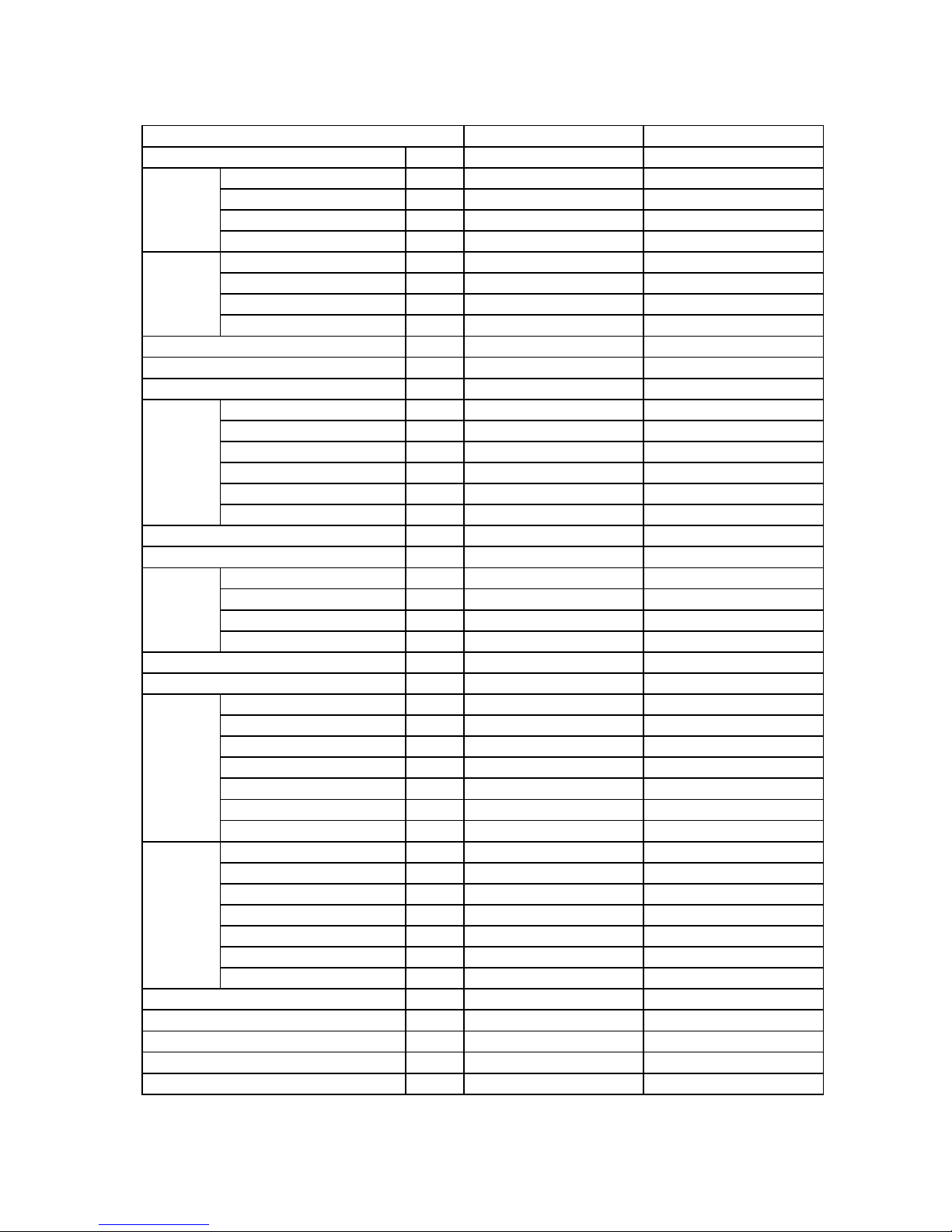
MPA-08CE MPA-08CR
Ph-V-Hz
115V,60Hz 115V,60Hz
Capacity Btu/h
8000 8000
Input W
850 850
Rated current A
7.4 7.4
EER Btu/w.h
9.4 9.4
Capacity Btu/h
----------------- -----------------
Input W
----------------- -----------------
Rated current A
----------------- -----------------
COP Btu/w.h
----------------- -----------------
L/h
1.1 1.1
L 5.5 5.5
A
39.7 39.7
Model EH120X1C-1BRU2 EH120X1C-1BRU2
Capacity Btu/h
8735 8735
Input W
840 840
Rated current(RLA) A
7.4 7.4
Thermal protector
UP3QE0591-T36 UP3QE0591-T36
Capacitor uF
45uF/ 250V 45uF/ 250V
g
550 550
MPa
2.1/0.9 2.1/0.9
Model
YSK40-6A-1 YSK40-6A-1
Input W 97/81/76/67 97/81/76/67
Capacitor uF
8uF/ 250V 8uF/ 250V
Speed(hi/mi/lo) r/min 1120/1060/1000/700 1120/1060/1000/700
m3/h
320 320
dB(A)
52 52
a.Number of rows
2 2
b.Tube pitch(a)x row pitch(b) mm
22X19.05 22X19.05
c.Fin spacing mm
1.4 1.4
d.Fin type (code) Hydrophilic aluminium Hydrophilic aluminium
e.Tube outside dia.and type mm
?7.94x0.35, innergroove tube ?7.94x0.35, innergroove tube
f.Coil length x height x width mm
274x264x38.1 274x264x38.1
g.Number of circuits
1 1
a.Number of rows
2 2
b.Tube pitch(a)x row pitch(b) mm
25.4x22 25.4x22
c.Fin spacing mm
1.5 1.5
d.Fin type (code) Unhydrophilic aluminium Unhydrophilic aluminium
e.Tube outside dia.and type mm
?9.52x0.27, innergroove tube ?9.52x0.27, innergroove tube
f.Coil length x height x width mm
497x304.8x22 515x304.8x22 497x304.8x22 515x304.8x22
g.Number of circuits
1 1
mm
387×830×456 387×830×456
Kg 37 37
℃
17-30 17-30
℃
10-35 10-35
m
2
12-18 12-18
Model
Power supply
Cooling
Heating
Moisture Removal
Water tank volume
Starting current
Compressor
Refrigerant type
Design pressure
Fan motor
Indoor air flow (Hi/Mi/Lo)
1.3 SPECIFICATION
2
Net weight
Operation temp
Ambient temp
Application area
Noise level (Hi/Mi/Lo)
Evaporator
Condenser
Dimension (W*H*D)
Page 4
MPA-08EE MPA-08ER
Ph-V-Hz
115V,60Hz 115V,60Hz
Capacity Btu/h
8000 8000
Input W
850 850
Rated current A
7.4 7.4
EER Btu/w.h
9.4 9.4
Capacity Btu/h
5000 5000
Input W
1500 1500
Rated current A
13.0 13.0
COP Btu/w.h
----------------- -----------------
L/h
1.1 1.1
L 5.5 5.5
A
39.7 39.7
Model EH120X1C-1BRU2 EH120X1C-1BRU2
Capacity Btu/h
8735 8735
Input W
840 840
Rated current(RLA) A
7.4 7.4
Thermal protector
UP3QE0591-T36 UP3QE0591-T36
Capacitor uF
45uF/ 250V 45uF/ 250V
g
550 550
MPa
2.1/0.9 2.1/0.9
Model
YSK40-6A-1 YSK40-6A-1
Input W 97/81/76/67 97/81/76/67
Capacitor uF
8uF/ 250V 8uF/ 250V
Speed(hi/mi/lo) r/min 1120/1060/1000/700 1120/1060/1000/700
m3/h
320 320
dB(A)
52 52
a.Number of rows
2 2
b.Tube pitch(a)x row pitch(b) mm
22X19.05 22X19.05
c.Fin spacing mm
1.4 1.4
d.Fin type (code) Hydrophilic aluminium Hydrophilic aluminium
e.Tube outside dia.and type mm
?7.94x0.35, innergroove tube ?7.94x0.35, innergroove tube
f.Coil length x height x width mm
274x264x38.1 274x264x38.1
g.Number of circuits
1 1
a.Number of rows
2 2
b.Tube pitch(a)x row pitch(b) mm
25.4x22 25.4x22
c.Fin spacing mm
1.5 1.5
d.Fin type (code) Unhydrophilic aluminium Unhydrophilic aluminium
e.Tube outside dia.and type mm
?9.52x0.27, innergroove tube ?9.52x0.27, innergroove tube
f.Coil length x height x width mm
497x304.8x22 515x304.8x22 497x304.8x22 515x304.8x22
g.Number of circuits
1 1
mm
387×830×456 387×830×456
Kg 37 37
℃
17-30 17-30
℃
≤35 ≤35
m
2
12-18 12-18
Model
Power supply
Cooling
Heating
Moisture Removal
Water tank volume
Starting current
Compressor
Refrigerant type
Design pressure
Fan motor
Indoor air flow (Hi/Mi/Lo)
3
Net weight
Operation temp
Ambient temp
Application area
Noise level (Hi/Mi/Lo)
Evaporator
Condenser
Dimension (W*H*D)
Page 5
1.4 FEATURES
All the models have two types of the cover and panel
structure.
No need for special installation. Four casters on the
bottom for easy movement and simple and convenient
use.
Only one exhaust pipe, and easier to use.
Remote-controlled or gentle-touch keys for easy and
comfortable use.
Compressors of famous brands are adopted for reliability
and low noise.
Multiple uses: dehumidifying and cloth drying.
The heating system uses PTC electrical heater and will not
be affected by ambient temperature, which saves energy.
Suitable for local cooling and heating.
Large volume tank, and convenient to use.
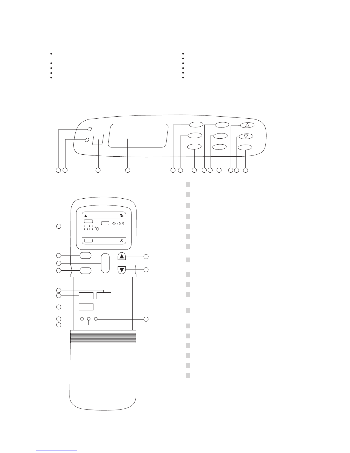
1.5 DISPLAY PANEL AND REMOTE CONTROL
DISPLAY PANEL
1
5432
1
Signal receiver
2
Heat/cool/dry lamp
3
Water full lamp
4
Operation display
5
1/0 button
AUTO COOL DRY HEAT FAN
TEMP
CLOCK
SPEED
AUTO LOW MED HIGH
MODE
1/0
TEMP/TIMER
FAN
SWING
CLOCK
SET
REMOTE CONTROL
6
8
5
6
7
D
E
F
G
H
A
9
I
6
Remote display
7
Mode button
8
9
Fan button
A
B
C
Swing button
D
Up button
E
Clock button
F
Reset button
G
Lock button
H
I
Timer on button
Timer off button
Display the situation of operation setting.
Select the operation mode, AUTO, COOL, DRY, HEAT
and FAN.
Press this button to operation the unit, again to stop.
Select the Fan speed, AUTO, LOW, MED, HIGH.
Press this button to activate the auto swing, again to
stop.
Press this button to increase the setting temperature
or Timer time.
Press this button to activate the time setting.
Press this button to reset all settings to original.
Press this button to lock all button except this button.
Press this button to activating TIMER ON time setting.
Press this button to activating TIMER OFF time setting.
WATER FULL
HEAT
COOL
DRY
1/0
FAN
SWING
MODE
ON
TIMER
OFF
CLOCK
TEMP./CLOCK
AD .
J
L R
Oo
C/ F
7 8
9
A B C D
Down button
Press this button to decrease the setting temperature
or Timer time.
Set button
Press this button to activate the Time ON/OFF setting.
Oo
C/ F button
Press this button to select temperature settings in
either Celsius or Farenheight .
`` `` `` ``
4
Page 6

Note: The Rear View and Side View as well as the performance of above styles are same as that of base style.
2.1 NAMES OF PARTS
The following models all are based on the model MPA-08CE and model MPA-O8EE Only change the external style.
FRONT VIEW
FRONT VIEW
FRONT VIEW
B Style
TOP
COVER
DRAIN TANK
FRONT VIEW
REAR VIEW
Base Style
ILLUMINATED
CONTROL PANEL
OSCILLATING
AIR VENTS
HANDLE
RECESS
DRAIN
TANK
CASTERS
AC POWER
CORD
EXHAUST AIR
OUTLET
SIDE VIEW
FILTER
COVER
A Style
TOP
COVER
OPERATION
COVER
DRAIN TANK
CASTERS
C Style
TOP
COVER
DRAIN
TANK
2. INSTALLATION
Installation Accessories
Description Quantity
Flexible exhaust hose with adapters..............3/set
13
stretches from 19 / " (50cm) up to 78 / " (200cm)
24
Window exhaust adapter(flat mouth)...............1Pc
Adjustable window/patio door slider kit.........2/set
53
from26 / " (67.5cm) up to 48 / "(203cm)
88
Drain hose connector.......................................1 Pc
continuous drain option (hose not included)
SPECIAL NOTE: Exterior drain hose extension
(direct drain) is not included with this unit and can
be purchased through any local Hardware Store.
Installation Accessories
Drain Hose Connector
Window Exhaust
Adapter
Adapter
Adapter
Adjustable Window/Patio Door Slider Kit
53
26/" - 48/
88
”
Flexible Exhaust Hose
13
19 / - 78 /
24
"
Adjustable Window/Patio Door Slider Kit
53
26 / - 48 /
88
”
"
"
"
5
Page 7

Window Kit Installation
Your window kit has been designed to fit most standard
"vertical"and "horizontal" window applications. However,
it may be necessary for you to improvise/modify some
aspects of the installation procedures for certain types
of windows. Please refer to Fig. 2 & Fig. 2a for minimum
and maximum window openings.
Before Starting This Unit
1) Select a suitable location, making sure you have easy
access to an electrical outlet.
2) Install the Flexible Exhaust Hose and the Adjustable
Window Slider Kit as depicted.
NOTE: Step 2 is required only while using the AIR
CONDITIONER MODE
3) Plug the unit into a 115V/60Hz grounded electrical
outlet.
DO NOT USE AN EXTENSION CORD.
4) Make sure the Water Tank is correctly positioned inside
the cabinet otherwise the unit will not operate.
5) To turn the unit on, press the I/O key (On/ Off Switch).
Water Tank Safety Feature
This unit is equipped with a fail-safe switch mechanism
which prevents the unit from condensing water in the
event the water tank is accidentally displaced, and/or
FULL with water. If this situation occurs, the unit will
signal 8 BEEPS and the WATER FULL indicator light
will flash red continuously until the water tank is correctly
positioned and/or emptied.
NOTE: The fan motor will continue to operate under this
condition. This is normal, but no cooling or
dehumidifying will occur until the tank is emptied and/or
correctly installed (It may take several minutes before the
compressor resumes normal operation).
2.2 Window Installation
Window Slider Kit
5
Minimum: 26 / "(67.5 cm )
8
3
Maximum: 48 / "(123cm)
8
Window Slider Kit
5
Minimum: 26 / "(67.5 cm )
8
3
Maximum: 48 / "(123cm)
8
Horizontal Window
Vertical
Window
6
Page 8

3. TROUBLE SHOOTING GUIDE
3.1 PIPING SYSTEM
The figure below is a brief description of the important components and their function in what is called the refrigeration system.
This will help to understand the refrigeration cycle and the flow of the refrigerant in the cooling cycle.
ROOM AIR CONDITIONER
CYCLE OF REFRIGERATION
EVAPORATOR
COMPLETE LIQUID BOIL
OFF POINT
COOLED
AIR
ROOM AIR HEAT LOAD
LIQUID
PRESSURE
DROP
(LIQUID REFRIGERANT)
CAPILLARY
OIL
COMPRESSOR
MOTOR
SUCTION LINE
COOL LOW
PRESSURE VAPOR
OUTSIDE COOLING
AIR FOR REFRIGERANT
PASS THROUGH
LIQUID OUTLET
HIGH PRESSURE VAPOR
LIQUID REFRIGERANT
LOW PRESSURE VAPOR
HOT DISCHARGE
AIR
VAPOR INLET
CONDENSER
3.2 ELECTRIC FUNCTION
3.2.1 Operational modes
3.2.1.1 Cooling mode
The air flow speed can be set at high, medium and
low; the fan can run continually in accordance with
the air flow speed.
oo
The temperature can be set from 16 C ~ -32 C.
The compressor starts operation when the ambient
temperature is higher than setpoint + 1 . When the
ambient temperature is lower than the setpoint, the
compressor stops.
3.2.1.2 Heating mode
The air flow speed can be set at high or low; the fan
actually operates at low and super low speed. When
the ambient temperature is higher than the setpoint,
the fan stops.
oo
The temperature can be set from 16 C ~ 32 C.
When the ambient temperature is lower than set point -1 , the PTC heater begins to work; when the
ambient temperature is higher than the setpoint,
the PTC heater stops.
3.2.1.3 Dehumidifying mode
oo
The temperature can be set from 10 C ~32 C.
The fan works at medium speed; the working
conditions of the compressor are the same as those
in cooling mode.
3.2.1.4 Fan only mode
The fan can run at high, medium or low speed.
`` ``
``
``
3.2.1
THE SETTING OF TIMER AND CLOCK
3.2.2.1
THE SETTING OF AUTO SWING
When the air conditioner is operating, press the
SWING key at any mode to start the auto swing
3.2.2
OFF TIMER
Set the OFF TIMER at any mode when the air condition is operating.
Press TIMER OFF or SET, the LED will display
TIMER OFF and flash with the close-down time.
Press TIMER up or TIMER down continually, you
can adjust the close-down time.
Press CLOCK key, you can verify the close-down
time.
3.2.2.2 ON TIMER
Set the starting up time before closing down the air
conditioner. And its starting up status will be the
working status of last time.
Press TIMER ON or SET, the LED will display
TIMER ON and flash with the operation time.
Press TIMER up or TIMER down continually, you
can adjust the close-down time.
Press CLOCK key, you can verify the operation time.
3.2.2.3 CLOCK
The clock displays time in the 24-hour system with
flashing at 1 Hz.
Setting:
At any mode, press and hold the CLOCK key for
more than 3 seconds, the clock display will flash at
1 Hz. Then press TIMER up or TIMER down, you
can adjust time.
Verifying:
Press CLOCK to verify.
3.2.3 TEMPERATURE SETTING
At cooling, dehumidifying or heating mode, you can
set the temperature. Press TEMP up key once, the
o
set-point increases for 1 C; press TEMP down key
o
once, the set-point decreases for 1 C.
3.2.4 FORCED OPERATION
3.2.4.1 When the power is turned on for the first time and no
other keys are pressed, press both CLOCK and
TEMP up. The machine instantly enters forced
heating mode.
3.2.4.2 When the power is turned on for the first time and
no other keys are pressed, press both CLOCK and
TEMP down. The machine instantly enters forced
cooling mode.
3.2.4.3 During the forced operation, you can set air flow,
auto swing, etc.
3.2.4.4 During the forced operation, press TEMP up or TEMP
down. You can see the pipe temperature Pxx and
room temperature Rxx at clock position.
3.2.4.5 Press I/O key or when the forced operation has
lasted for 30 minutes, the machine enters into
standby.
7
Page 9

3.2.5 PROTECTIVE FUNCTIONS
3.2.5.1 ALARM ON WATER TANK LEVER
At any mode, when the water tank level is up to the
limit, the buzzer alarms 8 times before it stops, the
alarm lamp flashes and the machine enters into air
blowing. (At heating mode, the machine keeps
original status.) The machine restores to former
operating status after the alarms go off. After 3
minutes, if the alarms can not go off, the machine
will enter into standby automatically.
3.2.5.2 LOW TEMPERATURE PROTECTION FOR THE
EVAPORATOR
At cooling and dehumidifying modes, if the pipe
o
temperature is lower than -3 C after compressor
runs for 10 minutes, the compressor will be shut
down instantly, the fan will start at high speed and
the green LED will flash at 1 Hz. When the pipe
o
temperature goes up to 10 C, the alarm goes off
and the machine operates at set conditions.
3.2.5.3 HIGH TEMPERATURE PROTECTION
At heating mode, when the temperature at air outlet
is too high, the PTC will be turned off (without
turning off the fan); when the temperature lowers
to normal, the PTC returns to work.
At heating mode, when the temperature above the
PTC is too high, the thermal fuse will be burnt out
and the power supply to PTC will be cut off.
At heating mode, when the temperature above PTC
increases abnormally, the PTC and the fan will be
turned off; red LED1 lamp flashes rapidly. When the
temperature lowers to normal, the machine returns
to work.
THE DELAYED PROTECTION FOR COMPRESSOR
When the power is on for the first time, the
compressor starts without waiting for 3 minutes;
re-starting the machine after the compressor is
stopped needs to wait for 3 minutes.
3.2.5.5 CURRENT PROTECTION FOR COMPRESSOR
During operation, if over-current lasts for 3 seconds,
the compressor will be shut down instantly and the
green LED1 flashes. After 3 minutes, the compressor
will re-start.
3.2.6 OTHER FUNCTIONS
3.2.6.1 FAN STARTING
When the fan works at medium, low, or super low
speed, there must be 3-second high speed starting.
3.2.6.2 THE INITIAL VALUES WHEN THE POWER IS ON
When the power is on, the starting status are:
MODE: FAN
FAN: HIGH
CLOCK: 12:00
There are no other displays
3.2.6.3 BUZZER
When the machine starts up, the buzzer sounds
twice. Press any key, the buzzer sounds once. When
there is water level alarm, the buzzer sounds 8 times.
3.2.5.4
3.3 TROUBLE SHOOTING GUIDE
ROOM AIR CONDITIONER VOLTAGE LIMITS
NAME PLATE RATING
MINIMUM MAXIMUM
115V 60Hz
98V 132V
8
Abnormal noise
Does this happen in
FAN ONLY mode?
Does this happen
without Auto Swing?
Yes
Check vertical
louver
Yes
No
Check swing
motor
Replace main
board
Check whether the
unit is on a flat, level
ground.
Remove the outdoor
discharging pipe.
Does it still happen?
Check the pipe, the
tie-in, the discharger.
Yes
Check motor
capacitor
Check fan
wheel
Check fan
motor
Replace main
board
Check air in-let and
out-let both inside
and outside
Check whether some
foam or other thing
is broken into fan in
the unit.
Check loosen part
No
Check loosen part
Check whether
there is collision
happened on pipes.
Check compressor
capacitor.
Check water depth
controller switch.
Is the noise coming
from inner pipe?
Check whether pipes
are collided flat.
Yes
Replace main
board
Replace
compressor
No
It is not faulty as the
refrigerant is flowing
in the pipe.
Page 10

9
No cooling
No operation
Is there indicator on
LCD?
Check power supply
and power cord
No
Check
transformer
Replace
display board
Replace main
board
Check wiring
Check room
temperature setting
Is the Water Full
lamp flashing?
Yes
Can the fan motor
operate?
Check wiring.
Yes
Check water
tank
Check water
depth controller
switch
Replace
display board
Replace main
board
No
No
Check fan motor
capacitor.
Is the voltage of
CN11 on main board
correct?
Replace main
board.
Yes
No
Replace fan
motor.
Yes
Check Whether the
evaporator or
condenser is
blocked.
Check compressor
capacitor.
Check temperature
sensor.
Is the voltage of
RL4 on main board
correct?
Replace compressor
Yes
No
Replace main board
No heating
Is there indicator on
LCD?
No
Can the fan motor
operate?
Check wiring.
Yes
No
Check over temp
protector on heater.
Is the voltage of
RL2 and RL3 on
main board correct?
Replace main
board.
Yes
No
Replace heater
Yes
Check compressor
over-current
protector
Page 11

10
Inefficient
cooling
Check wiring
Check room heat
load and windows
Check Whether the
evaporator or
condenser is
blocked.
Check compressor
and motor capacitor.
Check temperature
sensor.
Is the voltage of
RL4 and CN11 on
main board correct?
Check fan speed
Yes
No
Replace main board
Check air filter
Is temperature of
suction pipe on
compressor higher
o
than 19 C?
No
Replace compressor
Check leakage,
repair and recharge
refrigerant
Yes
Check room heat
load
Check the pipe, the
tie-in, the discharger.
Water seep from
unit
Check water tank
Check water stopper
Check heatinsulation foam inner
the unit.
Check water depth
controller switch
Replace main board
Check water pipe
in the unit.
Page 12

PROBLEM POSSIBLE CAUSE REMEDY
No power Check voltage at electrical outlet. Correct if none.
Transformer (Discharge
transformer before testing)
Check resistance between the two input/output lines on transformer.
Replace the transformer if either of the input/output is open or the
transformer is damaged.
Battery failure
Check the voltage of battery. Replace batteries if the voltage is lower
than 2.3V.
No power Check voltage at electrical outlet. Correct if none.
Power supply cord
Check voltage at the power cord termianl on Main board. Replace the
power cord if none.
Transformer (Discharge
transformer before testing)
Check resistance between the two input/output lines on transformer.
Replace the transformer if either of the input/output is open or the
transformer is damaged.
Wire disconnected or connection
loose
Connect wire. Refer to wiring diagram for termianl identification. Repair
or replace losse terminal.
Main board failure
Select fan speed and Check the voltage of CN11 on main board. Replace
the main board if no voltage.
Capacitor (Discharge capacitor
before testing)
Test capacitor.
Replace if not within +/-10% of manufacture's rating. Replace if shorted,
open or damaged.
Will not rotate
Fan blower hitting scroll. Realign assembly. Check
fan motor bearings. Replace the motor if motor shaft don't rotate.
Check voltage. Call an electrician if not within limits.
Test capacitor.
Replace if not within +/-10% of manufacture's rating.
Check bearings. Replace the motor if the fan blade cannot rotate freely.
Pay attention to any change from high speed to low speed. Replace the
motor if the speed does not change.
Fans Replace the fans if cracked, out of balance, or partially missing.
Loose screws Tighten them.
Worn bearings
Replace the motor if knocking sounds continue when running or loose,
or the motor hums or noise appears to be internal while running.
Copper tubing
Remove the cabinet and carefully rearrange tubing not to contact
cabinet, compressor, etc.
Discharging pipe
Check outdoor wind discharging pipe, the tie-in, the air discharger.
Correct if any problem. Replace if damaged.
Parts loosen Tighten them.
Compressor Replace after checked failure.
The ground is not level or not flat
enough
Place the unit on a flat, level ground.
Voltage Check voltage. Call an electrician if not within limits.
Wiring
Check the wire connections, if loose, repair or replace the terminal. If
wires are off, refer to wiring diagram for identification, and replace.
Check wire locations. If not per wiring diagram, correct.
Main board failure Check voltage RL4 of main board. Replace the main board if open.
Capacitor (Discharge capacitor
before testing)
Check the capacitor.
Replace if not within +/-10% of manufacturers rating. Replace if shorted,
open, or damaged.
Room temp sensor
Check the temperature setting if not at the coolest (in cooling mode) or
the heatest (in heating mode). Set it if not.
Pipe temp sensor
Check whether the evaporator is blocked. Check the pipe temp sensor
and replace if open circuit.
Water depth controller switch
Check whether the water tank is in correct postiong. Replace the water
depth controller switch if checked failure.
Over-current protector Replace after checked failure.
Compressor
Check the compressor for open circuit or ground. If open or grounded,
replace the compressor.
PROBLEM SOLVING
Check the voltage of CN7 on main board. Replace the display board after
checked faulty else replace the main board.
Fan motor will not run.
Remote control failure.
Display board or main PCB failure
No display on panel or
any one of the button
failure.
11
Revolves on overload.
Fan motor runs
intermittently
Fan motor noise.
Compressor will not run
while fan motor runs.
Excessive noise.
Page 13

PROBLEM POSSIBLE CAUSE REMEDY
Air filter Clean or replace if restricted.
Discharging pipe
Check outdoor wind discharging pipe, the tie-in, the air discharger.
Correct if any problem. Replace if damaged.
Unit undersized
Determine if the unit is properly sized for the area to be cooled or
heated.
Condenser and Evaporator Clean or replace if restricted.
Fan motor
Check the fan capacitor and replace if not within +/-10% of
manufactures rating.
Room structure and window kits
installation
Take proper measures or re-installate the windows kits to make the door
and windows sealed well if gap is found.
Air flow
Clean or remove if any barrier is found to block the inlet/outlet wind flow
of the unit.
Less refrigerant
Check the tubes for reasons of leakage. Recycle the refrigerant, correct
the leakage points and recharge.
Capillary tube
Regulate the flow if capillary tube and make the evaporating temerature
appropriate if the evaporator is frosted.
Compressor
The inlet and outlet valve of the compressor is damaged, making the low
pressure connected with the high pressure. The refrigerating system is
difficult to produce high pressure and low pressure. Replace the
compressor after checking for the reason.
Heat sources Reduce if too many.
Electric heater
Check the two over temp protectors. Replace if damaged. Replace after
the heater is checked faulty.
Refrigerant
The amount of the refrigerant is too much, making the compressor load
too big. Recycle and recharge the refrigerant after checking for the
reason.
Over-current protector Replace after checked failure.
Compressor The compressor is seized. Replace after checking for the reason.
Room temprature sensor Check and replace if the temprature is open or damaged.
Water depth controller switch
Check whether the water tank is in correct postiong. Replace the water
depth controller switch if checked failure.
Main board Check and replace the main board after checked failure.
Power supply
The input power supply voltage is too low. Call an electrician if not within
limits.
Main board
Check and replace the main board if the RL4 relay on main board is
shorted or damaged.
No power Check the voltage. Call an electrician if no within the limit.
Wiring Check the termianls. Repair and correct if loose.
Temperature setting Check and adjust the temperature setting.
Mode setting Check and adjust the mode setting.
Over-current protector Replace after checked failure.
Capacitor (Discharge capacitor
before testing)
Check the capacitor.
Replace if shorted, open, or damaged.
Compressor The compressor is damaged. Replace after checking for the reason.
Water depth controller switch
Check whether the water tank is in correct postiong. Replace the water
depth controller switch if checked failure.
Main board
Check the voltage of RL2 and RL3 on main board. Replace the main
board when the unit failure in heating mode.
Electric heater
Check the two over temp protectors. Replace if damaged. Replace after
the heater is checked faulty.
LCD is not clear LCD malfunction Replace LCD.
Transformer failure Check output voltage of transformer and replace after check faiulure.
Swing motor Replace after checked failure.
Wiring Correct according to wiring diagram.
Main board
Check the voltage of P1 on main board. Replace the main board after
checked failure.
Vertical louver is blocked Clean and repair after checked faulty.
PROBLEM SOLVING
12
No cooling or heating.
Insufficient cooling or
heating.
Stop instantly after
startup.
The compressor not to
stop even the room
temperature has got to
the setting temperature
or the water tank is full.
The unit starts and stops
frequently.
No auto swing
Page 14

13
4. SCHEMATIC DIAGRAM
4.1 CIRCUIT DIAGRAM
For Model MPA-08CE and MPA-08CR
For Model MPA-08EE and MPA-08ER
 Loading...