

Page 1

MCAC-UTSM-2012-12 R410A 50Hz Tropical Split AC
1
Content
Part 1 General Information ........................................... 2
Part 2 Indoor Units ........................................................ 6
Part 3 Outdoor Units ................................................... 91
Part 4 Installation ...................................................... 119
Part 5 Control ............................................................ 151
Page 2

R410A 50Hz Tropical Split AC MCAC-UTSM-2012-12
2
Part 1 General Information
1. Model Names of Indoor/Outdoor Units ............................. 3
2. External Appearance ......................................................... 4
3. Nomenclature ................................................................ ..... 5
Page 3
MCAC-UTSM-2012-12 R410A 50Hz Tropical Split AC
3
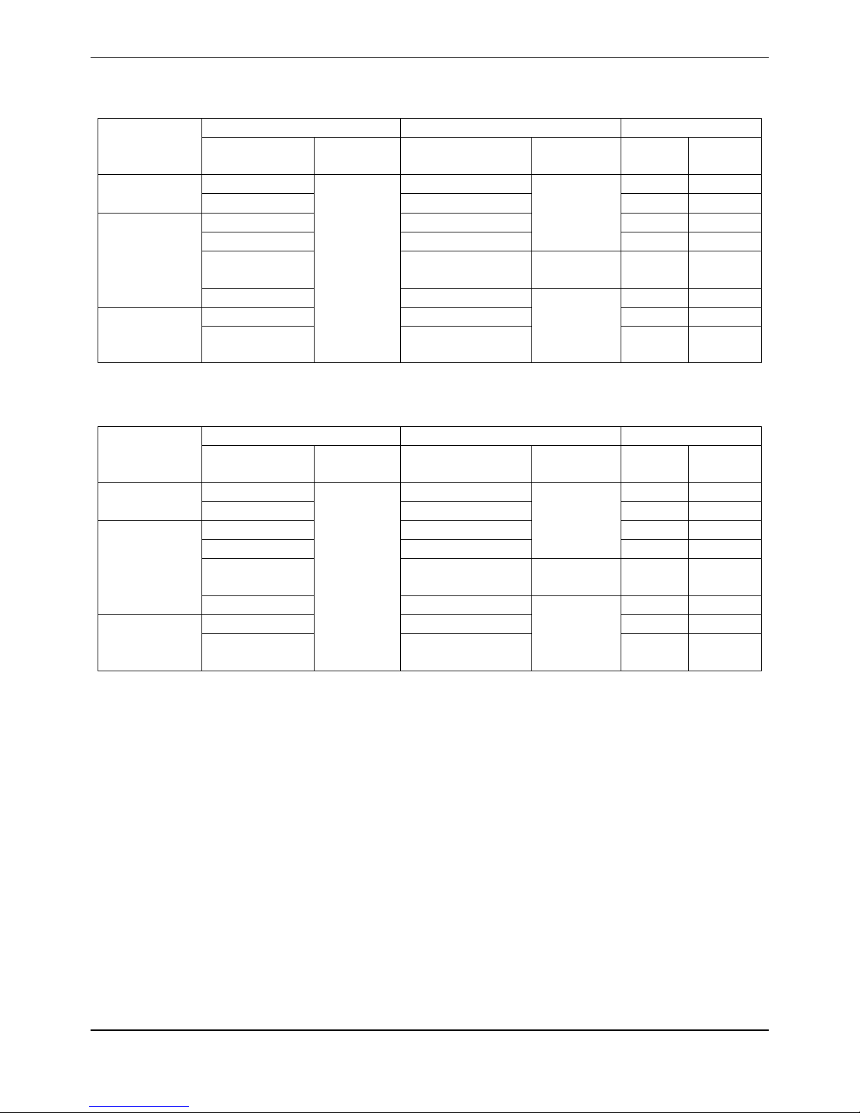
1. Model Names of Indoor/Outdoor Units
1.1 Model Names of Units with Cooling only:
Type
Indoor unit
Outdoor unit
Capacity
Model
Power
supply
Model
Power
supply
kW
Btu/h
Floor-standing
type
MFA-76CRN1
220~240V-
1Ph-50Hz
MOV-76CN1-C
380~415V-
3N-50Hz
22
76
MFA-96CRN1
MOV-96CN1-C
28
96
Mid-static
pressure duct
type
MTA-76CRN1
MOV-76CN1-C
22
76
MTA-96CRN1
MOV-96CN1-C
28
96
MTA-120CRN1
MOV-120CN1-C
380~400V-
3N-50Hz
35
120
MTA-150CRN1
MOV-76CN1-C *2
380~415V-
3N-50Hz
44
150
High-static
pressure
duct type
MHB-76CRN1
MOV-76CN1-C
22
76
MHB-96CRN1
MOV-96CN1-C
28
96
1.2 Model Names of Units with Cooling and heating:
Type
Indoor unit
Outdoor unit
Capacity
Model
Power
supply
Model
Power
supply
kW
Btu/h
Floor-standing
type
MFA-76HRN1
220~240V-
1Ph-50Hz
MOV-76HN1-C
380~415V-
3N-50Hz
22
76
MFA-96HRN1
MOV-96HN1-C
28
96
Mid-static
pressure duct
type
MTA-76HRN1
MOV-76HN1-C
22
76
MTA-96HRN1
MOV-96HN1-C
28
96
MTA-120HRN1
MOV-120HN1-C
380~400V-
3N-50Hz
35
120
MTA-150HRN1
MOV-76HN1-C *2
380~415V-
3N-50Hz
44
150
High-static
pressure duct
type
MHB-76HRN1
MOV-76HN1-C
22
76
MHB-96HRN1
MOV-96HN1-C
28
96
Page 4
R410A 50Hz Tropical Split AC MCAC-UTSM-2012-12
4
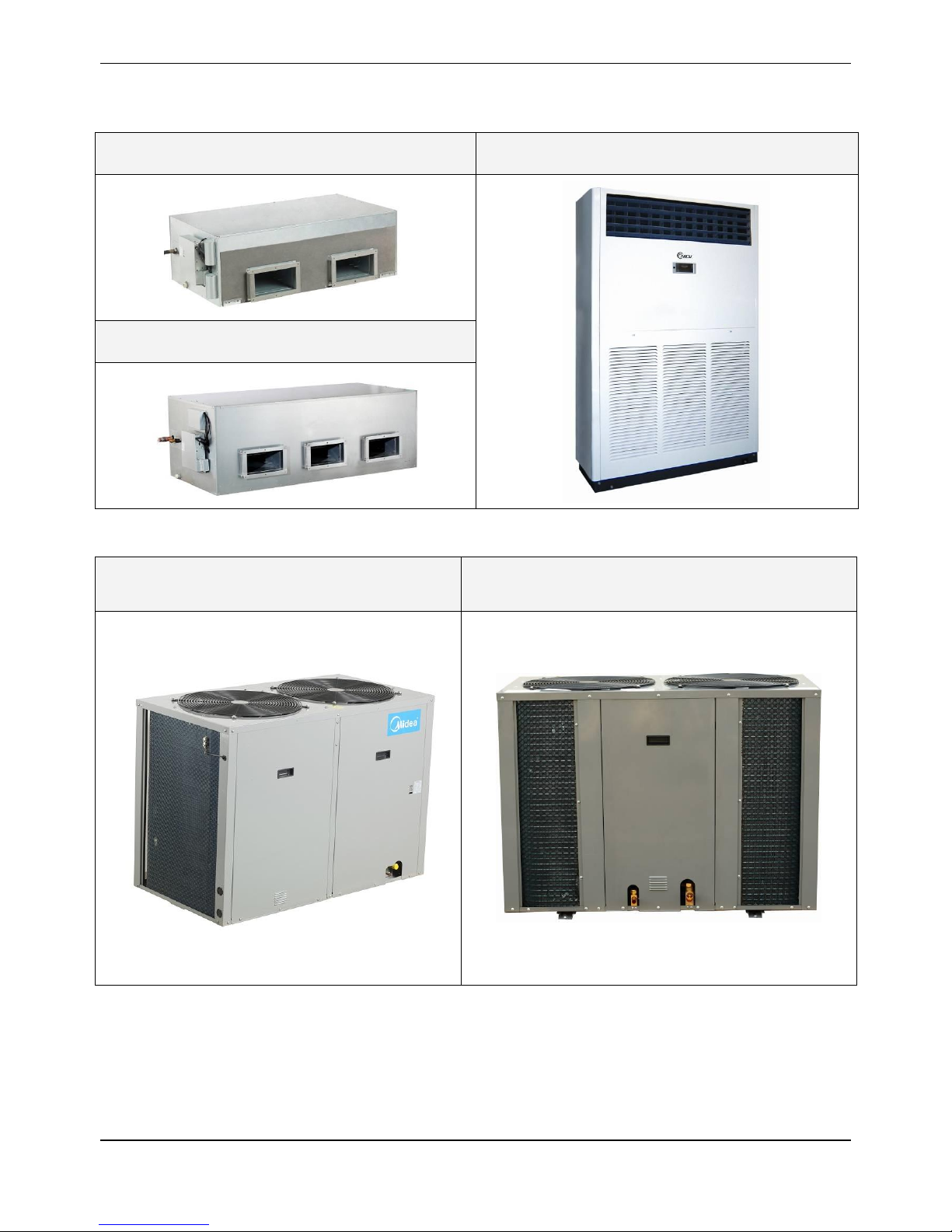
2. External Appearance
2.1 Indoor Units
MTA-76C(H)RN1
MTA-96C(H)RN1
MFA-76C(H)RN1
MFA-96C(H)RN1
MTA-120CRN1\MTA-120HRN1
MTA-150CRN1
2.2 Outdoor Unit
MOV-76C(H)N1-C
MOV-96C(H)N1-C
MOV-150C(H)N1-C (MOV-76C(H)N1-C*2)
MOV-120C(H)N1-C
Page 5

MCAC-UTSM-2012-12 R410A 50Hz Tropical Split AC
5
3. Nomenclature
3.1 Indoor unit:
3.2 Outdoor unit:
M T A – 76 C R N1
None:R22;N1:R410a
R:Remote Controller
Function Code: C: Cooling
H: Cooling and Heating
Cooling Capacity (*76 kBtu/h)
Product Series
A: 1st time design
B: 2nd time design
Indoor Units
T: Duct type
F: Floor-standing type
H: High static pressure
Midea
Design times
None:R22;
N1:R410a
Function Code:
C: Cooling Only
H: Heat pump
Cooling Capacity (76 kBtu/h)
Universal Outdoor Unit
Outdoor Unit
Midea
M O V 76 C N1 - C
Page 6

R410A 50Hz Tropical Split AC MCAC-UTSM-2012-12
6
Part 2 Indoor Units
Duct Type ............................................................................... 7
Floor-standing Type ............................................................. 59
Page 7

MCAC-UTSM-2012-12 R410A 50Hz Tropical Split AC
7
Duct Type
1. Features .............................................................................. 8
2. Specifications .................................................................... 9
3. Dimensions ...................................................................... 12
4. Service Space .................................................................. 14
5. Piping Diagrams .............................................................. 16
6. Wiring Diagrams .............................................................. 16
7.Capacity Table ................................................................... 21
8. Static Pressure ................................................................. 34
9. Electric Characteristics ................................................... 37
10. Sound Levels ................................................................. 38
11. Exploded View ................................................................ 39
12. Troubleshooting ............................................................. 50
13. Accessories .................................................................... 58
Page 8

R410A 50Hz Tropical Split AC MCAC-UTSM-2012-12
8
1. Features
1. Nested in the ceiling, space-saving and noble.
2. High capacity of cooling/heating, efficient, and energy-saving.
3. The air outlet is laid out according to you desire.
4. Economic and convenient installation
1) Several diffusers branch off from an indoor unit, adjusting the room temperature, which makes many
rooms to be air-conditioned with only one indoor unit.
2) All models feature thin design making them applicable to ceiling pocket that tends to be shallow
5. Way of air intake and inserting air filter
6. It is suitable be used for office, hospital, commercial place and home, the air conditioner will create the
comfortable and elegance environment for you.
Page 9
MCAC-UTSM-2012-12 R410A 50Hz Tropical Split AC
9
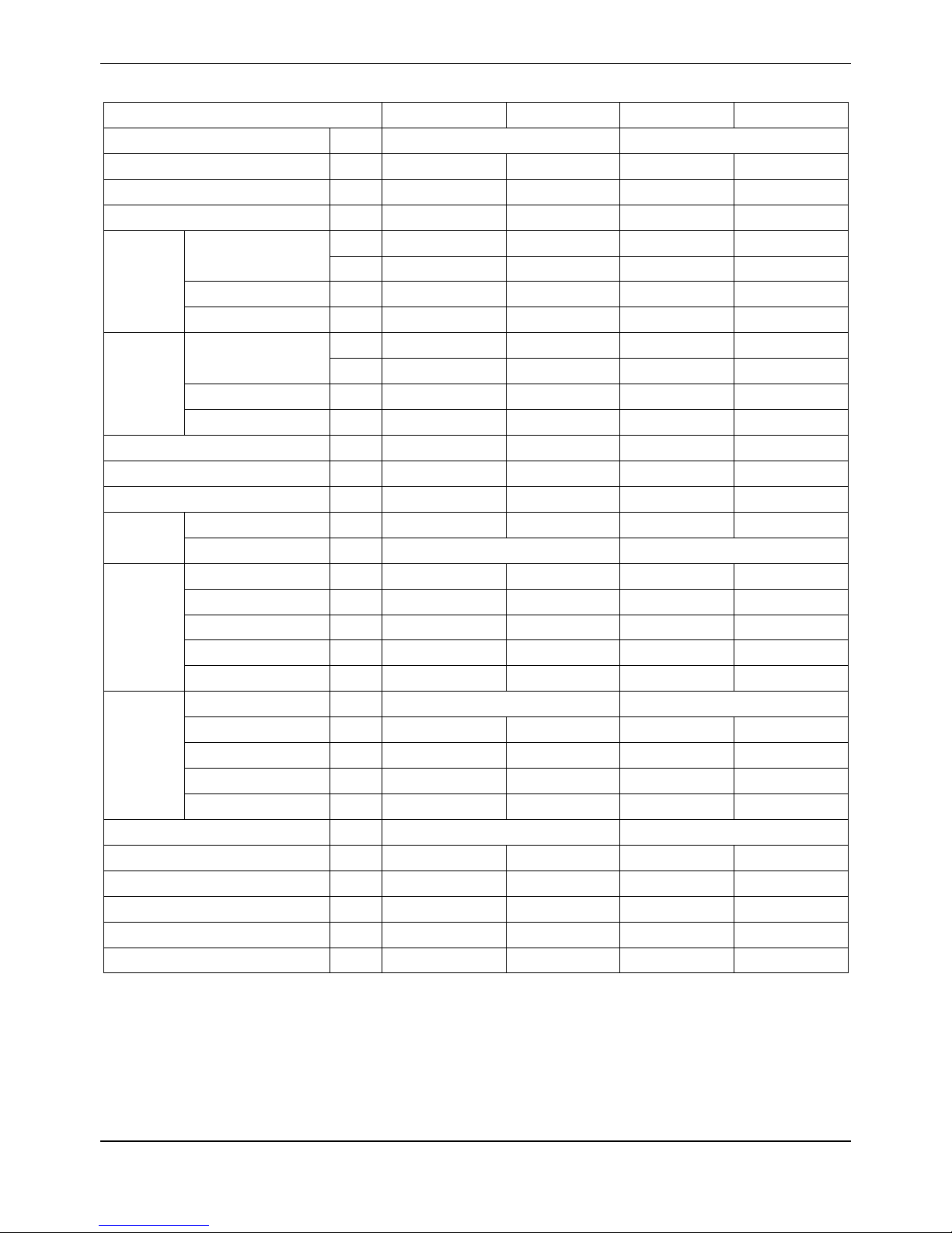
2. Specifications
Model
MTA-76CRN1
MTA-76HRN1
MTA-96CRN1
MTA-96HRN1
Power supply
-
220~240V-1Ph-50Hz
220~240V-1Ph-50Hz
Temp. setting range
℃
17~32
20~27
17~32
20~27
Rated input power
W
11700
11700
14400
14400
Rated current
A
19.3
19.3
23.7
23.7
Cooling
Capacity
Btu/h
75100
75100
95600
95600
W
22000
22000
28000
28000
Input W 7500
7500
9600
9600
EER
W/W
2.93
2.93
2.92
2.92
Heating
Capacity
Btu/h / 85300
/
105800 W /
25000
/
31000
Input W /
8300
/
10300
COP
W/W / 3.01 / 3.01
Indoor air flow(Hi/Med/Lo)
m3/h
4250/3835/3485
4250/3835/3485
5100/4520/3980
5100/4520/3980
Indoor standard ESP(Hi)
Pa
100
100
100
100
Indoor noise level(Hi)
dB(A)
54
54
55
55
Refrigerant
Type - R410A
R410A
R410A
R410A
Control
-
Capillary
Capillary
Fan
Type - Centrifugal fan
Centrifugal fan
Centrifugal fan
Centrifugal fan
Dimension
mm
Φ307
Φ307
Φ307
Φ307
Drive type - Direct
Direct
Direct
Direct
Motor input* No.
W
446*2
446*2
725*2
725*2
Motor speed
rpm
877
877
1136
1136
Coil
Type - Copper tube and aluminum fin
Copper tube and aluminum fin
Tube size
mm
Φ9.52
Φ9.52
Φ9.52
Φ9.52
No. of rows - 3 3 4
4
Fin per inch
FPI
17
17
17
17
Length* height
mm
1200*406.4
1200*406.4
1200*406
1200*406
Controller - Remote controller
Remote controller
Drain pipe size
mm
41
41
41
41
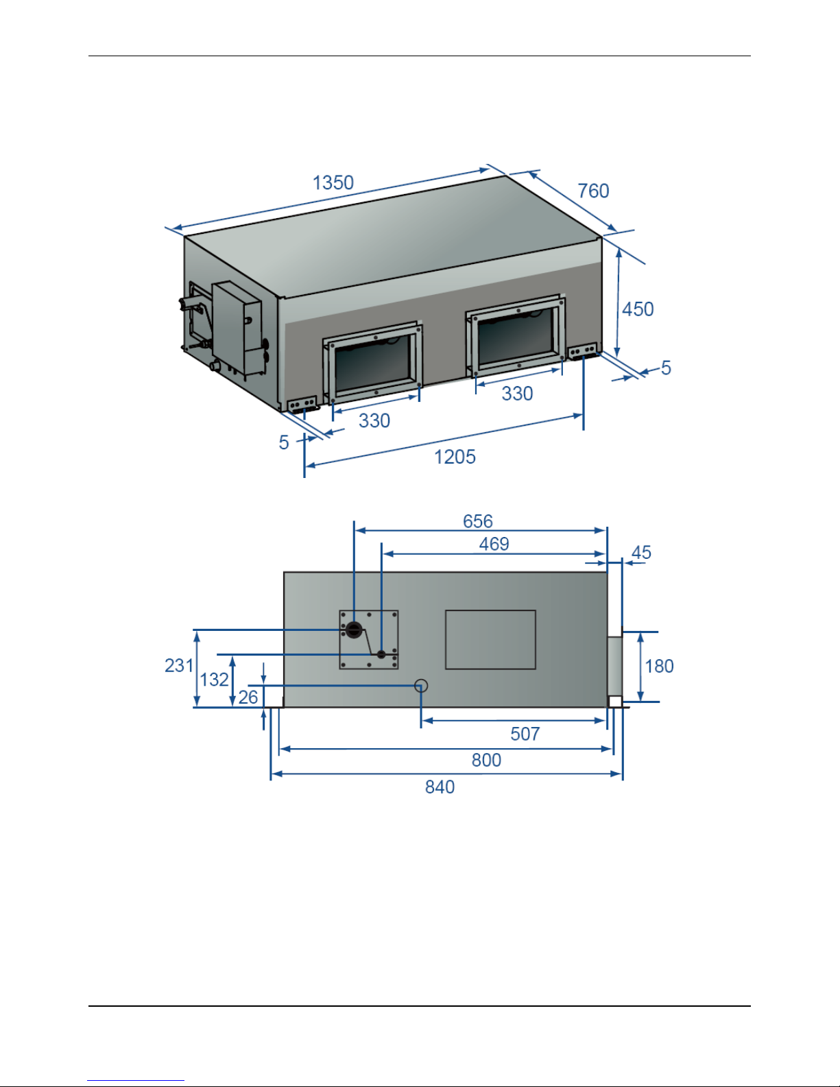
Dimension (W*H*D)
mm
1350*450*760
1350*450*760
1350*450*760
1350*450*760
Packing (W*H*D)
mm
1549*476*917
1549*476*917
1549*476*917
1549*476*917
Net/Gross weight
kg
105/120
105/120
105/120
105/120
Shipping Qty.(20’/40’/40’HQ)
pcs.
30/64/64
30/64/64
30/64/64
30/64/64
Notes:
1. ESP: external static pressure
2. Nominal cooling capacities are based on the following conditions:
Indoor temp: 27°CDB, 19°CWB; Outdoor temp: 35°CDB, 24°C WB; Equivalent refrigerant piping: 7.5m (horizontal).
3. Nominal heating capacities are based on the following conditions:
Indoor temp: 20°CDB, 15°C WB; Outdoor temp: 7°CDB, 6°CWB; Equivalent refrigerant piping: 7.5m (horizontal).
Page 10

R410A 50Hz Tropical Split AC MCAC-UTSM-2012-12
10
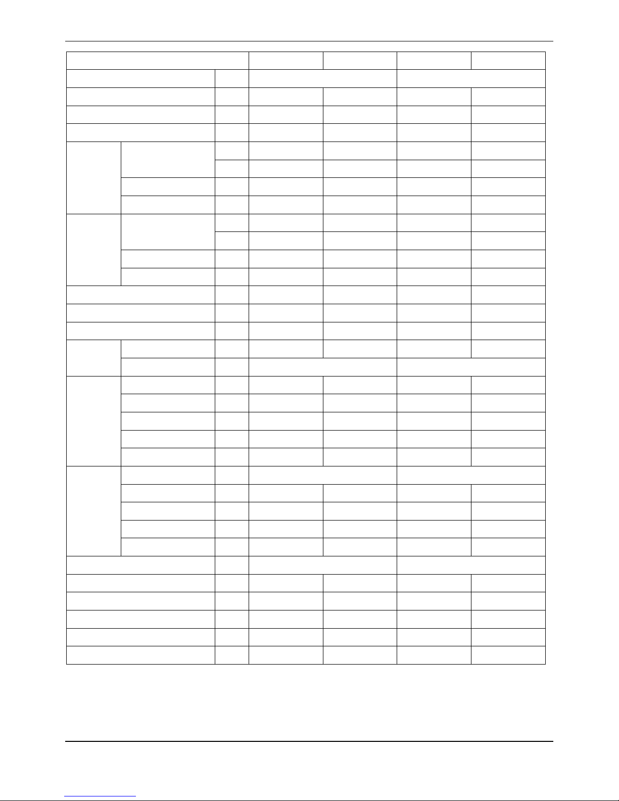
Model
MTA-120CRN1
MTA-120HRN1
MTA-150CRN1
MTA-150HRN1
Power supply
-
220~240V-1Ph-50Hz
220~240V-1Ph-50Hz
Temp. setting range
℃
17~32
20~27
17~32
20~27
Rated input power
W
17300
17300
21200
21200
Rated current
A
28.6
28.6
35
35
Cooling
Capacity
Btu/h
119400
119400
150100
150100
W
35000
35000
44000
44000
Input W 12000
12000
15100
15100
EER
W/W
2.92
2.92
2.91
2.91
Heating
Capacity
Btu/h
/
129700
/
160300
W
/
38000
/
47000
Input W /
12600
/
15700
COP
W/W / 3.02 / 3
Indoor air flow(Hi/Med/Lo)
m3/h
6375/5710/5040
6375/5710/5040
7650/6920/6320
7650/6920/6320
Indoor standard ESP(Hi)
Pa
150
150
150
150
Indoor noise level(Hi)
dB(A)
56
56
56
56
Refrigerant
Type - R410A
R410A
R410A
R410A
Control
-
Capillary
Capillary
Fan
Type - Centrifugal fan
Centrifugal fan
Centrifugal fan
Centrifugal fan
Dimension
mm
Φ307
Φ307
Φ307
Φ307
Drive type - Direct
Direct
Direct
Direct
Motor input * No.
W
498*3
498*3
630*3
630*3
Motor speed
rpm
860
860
1202
1202
Coil
Type - Copper tube and aluminum fin
Copper tube and aluminum fin
Tube size
mm
Φ7
Φ7
Φ7
Φ7
No. of rows 4 4 4
4
Fin per inch
FPI
17
17
17
17
Length* height
mm
1602*588
1602*588
1602*588
1602*588
Controller - Remote controller
Remote controller
Drain pipe size
mm
41
41
41
41
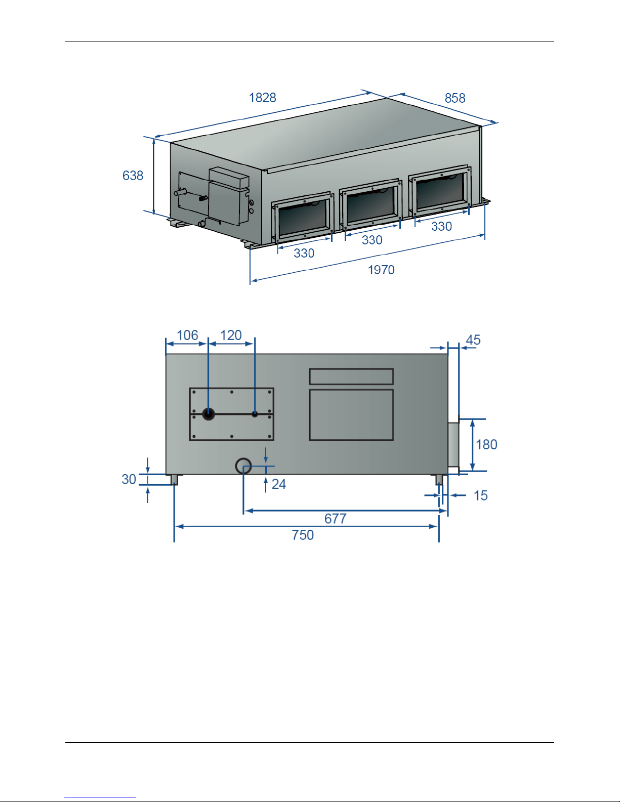
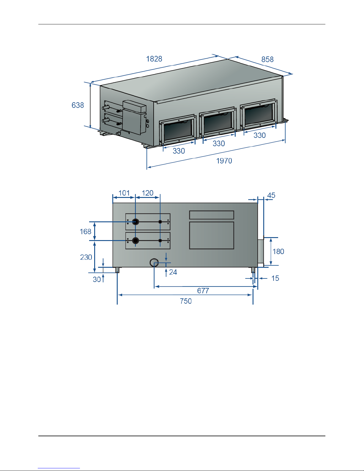
Dimension (W*H*D)
mm
1828*638*858
1828*638*858
1828*638*858
1828*638*858
Packing (W*H*D)
mm
2095*689*929
2095*689*929
2095*689*929
2095*689*929
Net/Gross weight
kg
188/220
188/220
188/200
188/200
Shipping Qty per (20'/40'/40'HD)
pcs
19/42/46
19/42/46
19/42/46
19/42/46
Notes:
1. ESP: external static pressure
2. Nominal cooling capacities are based on the following conditions:
Indoor temp: 27°CDB, 19°CWB; Outdoor temp: 35°CDB, 24°C WB; Equivalent refrigerant piping: 7.5m (horizontal).
3. Nominal heating capacities are based on the following conditions:
Indoor temp: 20°CDB, 15°C WB; Outdoor temp: 7°CDB, 6°CWB; Equivalent refrigerant piping: 7.5m (horizontal).
Page 11
MCAC-UTSM-2012-12 R410A 50Hz Tropical Split AC
11
Model
MHB-76CRN1
MHB-76HRN1
MHB-96CRN1
MHB-96HRN1
Power supply
-
220~240V-1Ph-50Hz
220~240V-1Ph-50Hz
Temp. setting range
℃
17~32
20~27
17~32
20~27
Rated input power
W
11700
11700
14400
14400
Rated current
A
19.3
19.3
23.7
23.7
Cooling
Capacity
Btu/h
75100
75100
95500
95500
W
22000
22000
28000
28000
Input power
W
7500
7500
9600
9600
EER
W/W
2.93
2.93
2.92
2.92
Heating
Capacity
Btu/h / 85300
/
105800 w /
25000
/
31000
Input power W /
8300
/
10300
COP
W/W / 3.01
/
3.01
Indoor air flow (Hi/Med/Lo)
m3/h
4250/3620/3025
4250/3620/3025
5100/4580/3980
5100/4580/3980
Indoor standard ESP(Hi)
Pa
196
196
196
196
Indoor noise level (Hi)
dB(A)
53
53
54
54
Refrigerant
Type - R410A
R410A
R410A
R410A
Control
-
Capillary
Capillary
Fan
Type - Centrifugal fan
Centrifugal fan
Centrifugal fan
Centrifugal fan
Dimension
mm
Φ307
Φ307
Φ307
Φ307
Drive type - Direct
Direct
Direct
Direct
Motor input* No.
W
663*2
663*2
788*2
788*2
Motor speed
rpm
1022/871/758
1022/871/758
1135/983/845
1135/983/845
Coil
Type - Copper tube and aluminum fin
Copper tube and aluminum fin
Tube size
mm
Φ9.52
Φ9.52
Φ9.52
Φ9.52
No. of rows - 3 3 4
4
Fin per inch
FPI
17
17
17
17
Length*Height
mm
1200*406.4
1200*406.4
1200*406
1200*406
Controller - Remote controller
Remote controller
Drain pipe size
mm
41
41
41
41
Dimension (W*H*D)
mm
1350*450*760
1350*450*760
1350*450*760
1350*450*760
Packing (W*H*D)
mm
1549*476*917
1549*476*917
1549*476*917
1549*476*917
Net/Gross weight
kg
105/120
105/120
105/120
105/120
Shipping Qty per (20'/40'/40'HD)
pcs
30/64/64
30/64/64
30/64/64
30/64/64
Notes:
1. ESP: external static pressure
2. Nominal cooling capacities are based on the following conditions:
Indoor temp: 27°CDB, 19°CWB; Outdoor temp: 35°CDB, 24°C WB; Equivalent refrigerant piping: 7.5m (horizontal).
3. Nominal heating capacities are based on the following conditions:
Indoor temp: 20°CDB, 15°C WB; Outdoor temp: 7°CDB, 6°CWB; Equivalent refrigerant piping: 7.5m (horizontal).
Page 12
R410A 50Hz Tropical Split AC MCAC-UTSM-2012-12
12
3. Dimensions
3.1 MTA-76C(H)RN1, MTA-96C(H)RN1, MHB-76C(H)RN1, MHB-96C(H)RN1
Page 13
MCAC-UTSM-2012-12 R410A 50Hz Tropical Split AC
13
3.2 MTA-120C(H)RN1
Page 14
R410A 50Hz Tropical Split AC MCAC-UTSM-2012-12
14
3.3 MTA-150C(H)RN1
Page 15
MCAC-UTSM-2012-12 R410A 50Hz Tropical Split AC
15
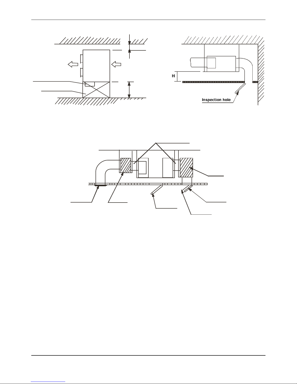
4. Service Space
Electric control box
Inspection hole
≥
6
0
0
m
m
≥
5
0
0
m
m
Top view Side view
Inspection
Canvas adapter
Muffle
Air outlet
Air inlet
Air filter
hole
Muffle
Air duct system
Page 16
R410A 50Hz Tropical Split AC MCAC-UTSM-2012-12
16
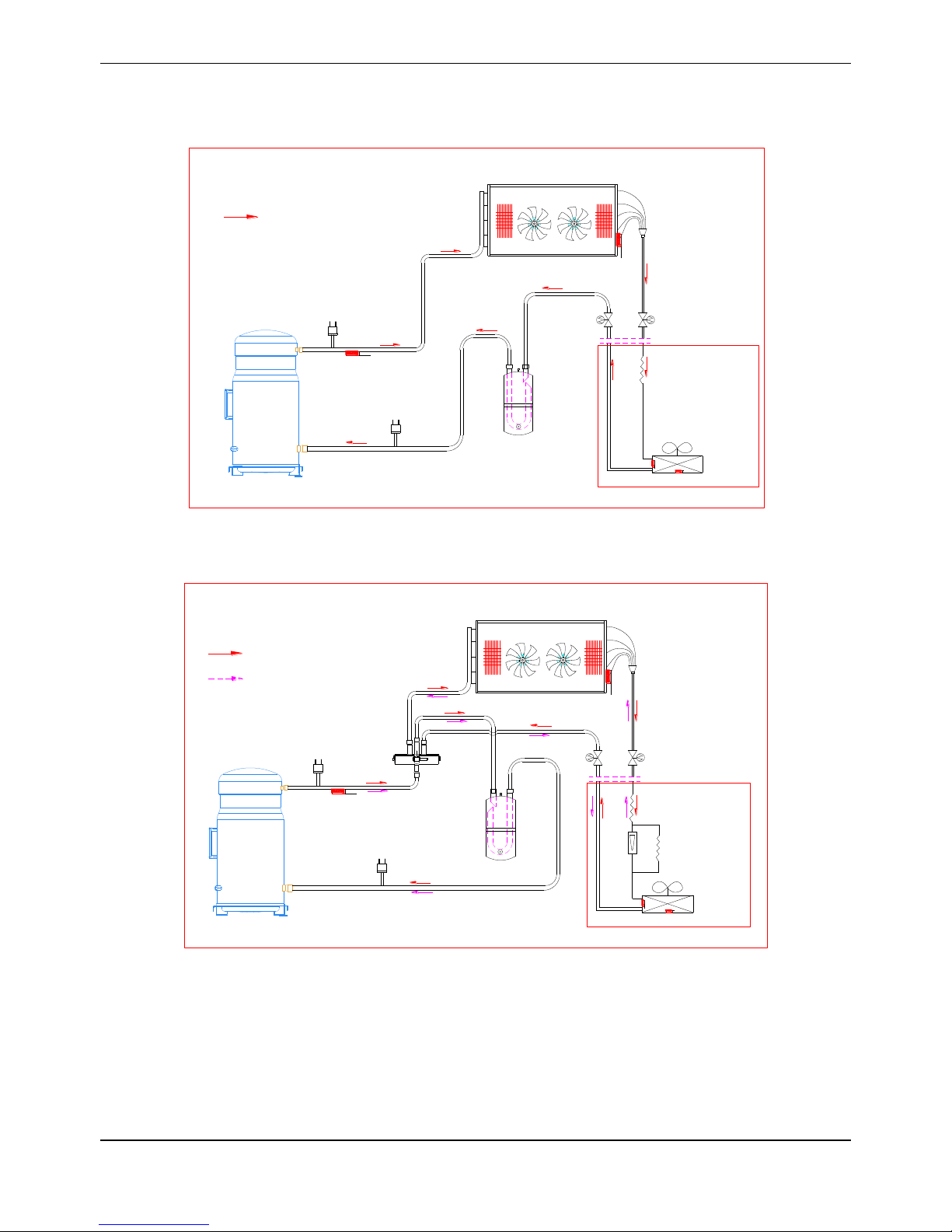
5. Refrigerant cycle diagram
5.1 Cooling only: MTA-76CRN1, MTA-96CRN1, MTA-120CR N1, MTA-150CR N1
MHB-76CRN1, MHB-96CRN1
Discharge temp. sensor
HP Switch
Compressor
Liquid-gas seperator
Outdoor heat-exchanger
Stop valve
Stop valve
Indoor unit
LP Switch
T4
T2
T3
Cooling
Indoor
heat-exchanger
5.2 Cooling and heating: MTA-76HRN1, MTA-96HRN1, MTA-120HRN1
MHB-76HRN1, MHB-96HRN1
Discharge temp. sensor
HP Switch
Compressor
4-way valve
Liquid-gas seperator
Outdoor heat-exchanger
Stop valve
Stop valve
Indoor unit
Check valve
LP Switch
T4
T2
T3
Heating
Cooling
Indoor
heat-exchanger
Capillary
Capillary
Page 17
MCAC-UTSM-2012-12 R410A 50Hz Tropical Split AC
17
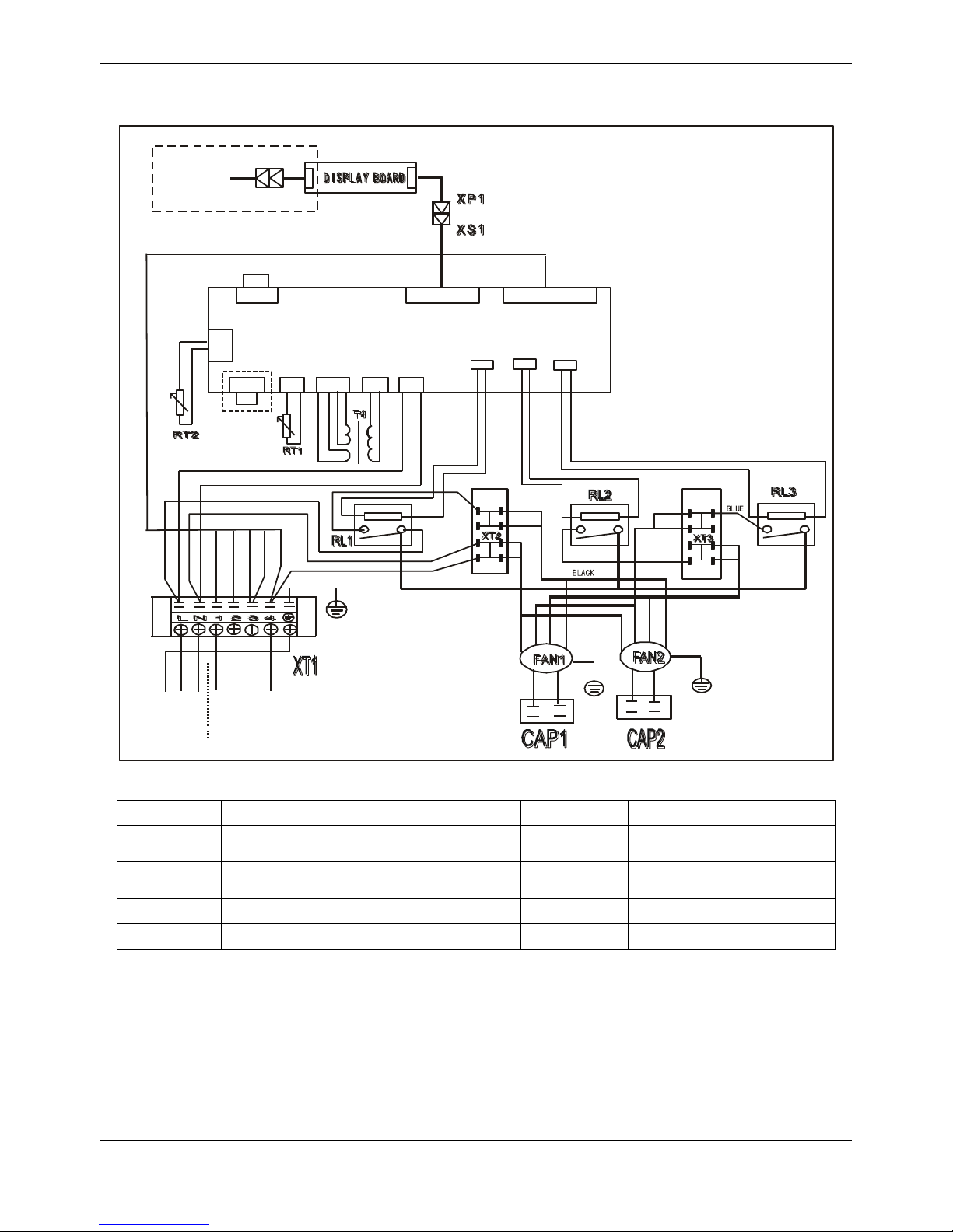
6. Wiring Diagrams
6.1 MTA-76CRN1, MTA-96CRN1, MHB-76CRN1, MHB-96CRN1
INDOOR POWER
Y
E
L
L
O
W
G
R
E
E
N
B
R
O
W
N
B
L
U
E
R
E
D
B
L
U
E
R
E
D
W
H
I
T
E
RED RED
WHITE
SLOW
HIGH
LOW
BLUE
TO OUTDOOR
B
L
A
C
K
Y
E
L
L
O
W
R
E
D
WHITE
B
L
U
E
Y/G
B
L
A
C
K
R
E
D
WHITE
B
L
U
E
Y/G
MAIN C ONTROL BO ARD
WHITE
(GRAY)
WHITE
(GRAY)
CN20 CN7 CN3 CN2 CN1
CN8
CN11 CN10 CN15
TO WIRE
CONTROLLER
RL1 RL2 RL3
BLUE
RED
B
R
O
W
N
B
R
O
W
N
B
R
O
W
N
B
R
O
W
N
B
R
O
W
N
B
R
O
W
N
Y
E
L
L
O
W
BLACK
B
L
A
C
K
R
E
D
B
L
U
E
Y
E
L
L
O
W
Y/G
RED
WHITE
B
L
U
E
B
L
U
E
N-LINE
R
E
D
BLACK
Item
Name
Item
Name
Item
Name
CAP1-CAP2
Indoor fan cap
CN1-3,CN7,CN8, CN10,
CN11,CN15,CN20
PCB sockets
T4
Transformer
FAN1-FAN2
Indoor fan
RT1
Room temp.
sensor
RT2
Pipe temp.
sensor
XP1
Connector
XS1
Connector
XT1
7-way terminal
XT2,XT3
Mid terminal
RL1,RL2,RL3
Relay
-
-
Page 18
R410A 50Hz Tropical Split AC MCAC-UTSM-2012-12
18
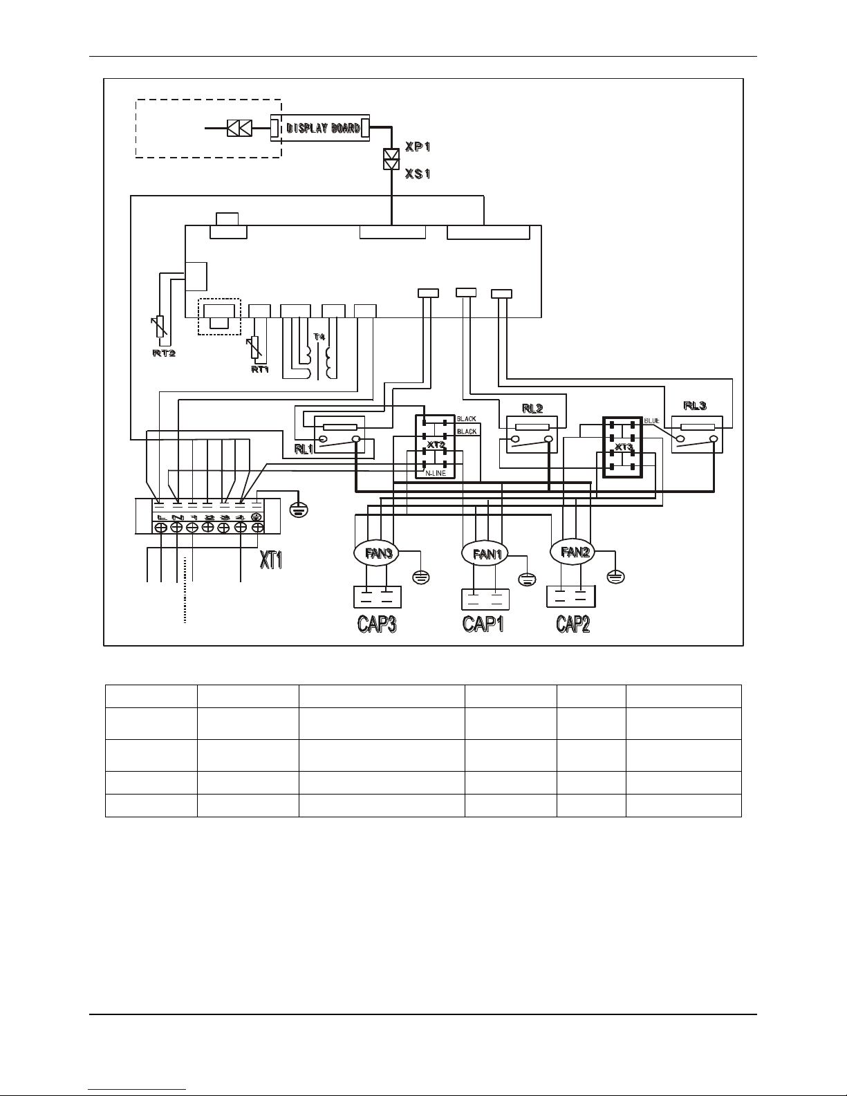
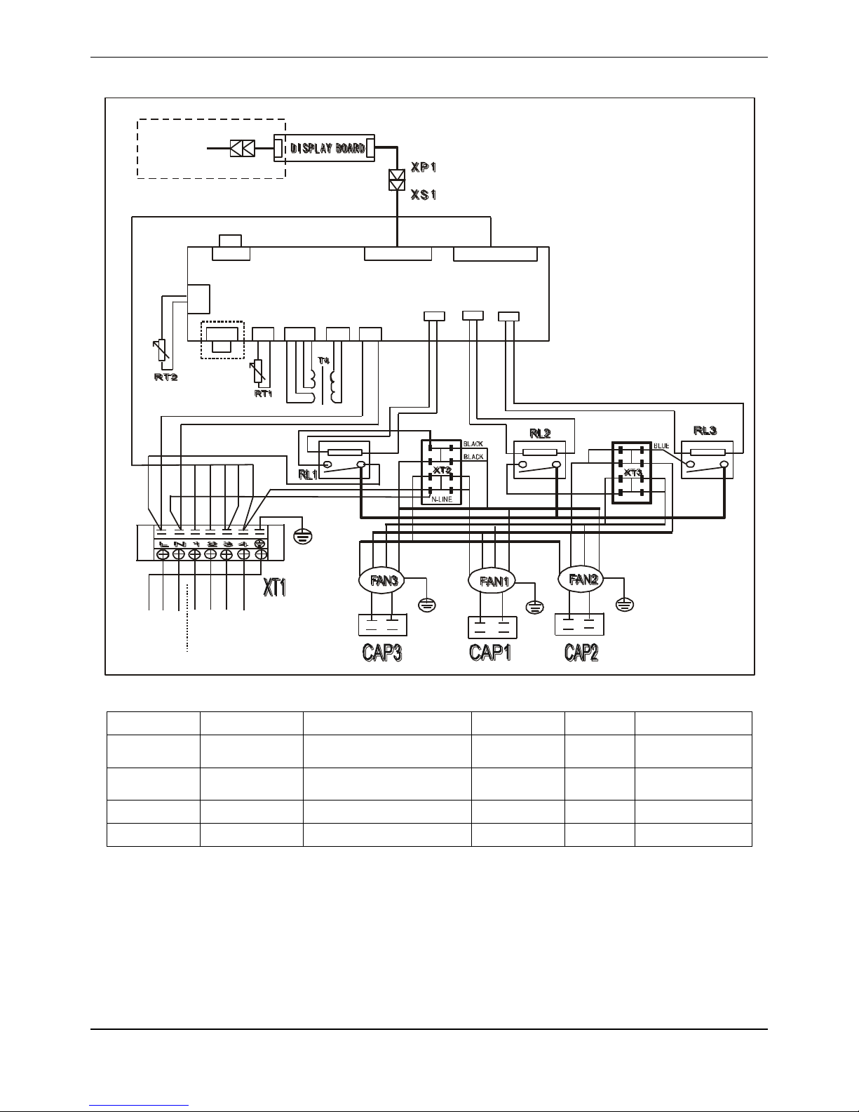
6.2 MTA-120CRN1, MTA-150CRN1
INDOOR POWER
B
L
A
C
K
Y
E
L
L
O
W
Y
E
L
L
O
W
G
R
E
E
N
B
R
O
W
N
B
L
U
E
R
E
D
B
L
U
E
R
E
D
R
E
D
WHITE
RED RED
WHITE
WHITE
(GRAY)
WHITE
SLOW
HIGH
LOW
BLUE
BLUE
RED
TO OUTDOOR
Y/G
B
L
A
C
K
Y
E
L
L
O
W
R
E
D
WHITE
B
L
U
E
Y/G
B
L
A
C
K
R
E
D
WHITE
B
L
U
E
Y/G
MAIN CONTROL BOARD
WHITE
(GRAY)
WHITE
(GRAY)
CN20 CN7 CN3 CN2 CN1
CN8
CN11 CN10 CN15
TO WIRE
CONTROLLER
RL1 RL2 RL3
BLUE
RED
B
R
O
W
N
B
R
O
W
N
B
R
O
W
N
B
R
O
W
N
B
R
O
W
N
B
R
O
W
N
B
L
U
E
Y
E
L
L
O
W
B
L
A
C
K
B
L
A
C
K
R
E
D
R
E
D
B
L
U
E
B
L
U
E
Y
E
L
L
O
W
Y
E
L
L
O
W
Y/G
WHITE
R
E
D
BLACK
Item
Name
Item
Name
Item
Name
CAP1-CAP3
Indoor fan cap
CN1-3,CN7,CN8,
CN10,CN11,CN15,CN20
PCB sockets
T4
Transformer
FAN1-FAN3
Indoor fan
RT1
Room temp.
sensor
RT2
Pipe temp.
sensor
XP1
Connector
XS1
Connector
XT1
7-way terminal
XT2,XT3
Mid terminal
RL1,RL2,RL3
Relay
-
-
Page 19
MCAC-UTSM-2012-12 R410A 50Hz Tropical Split AC
19
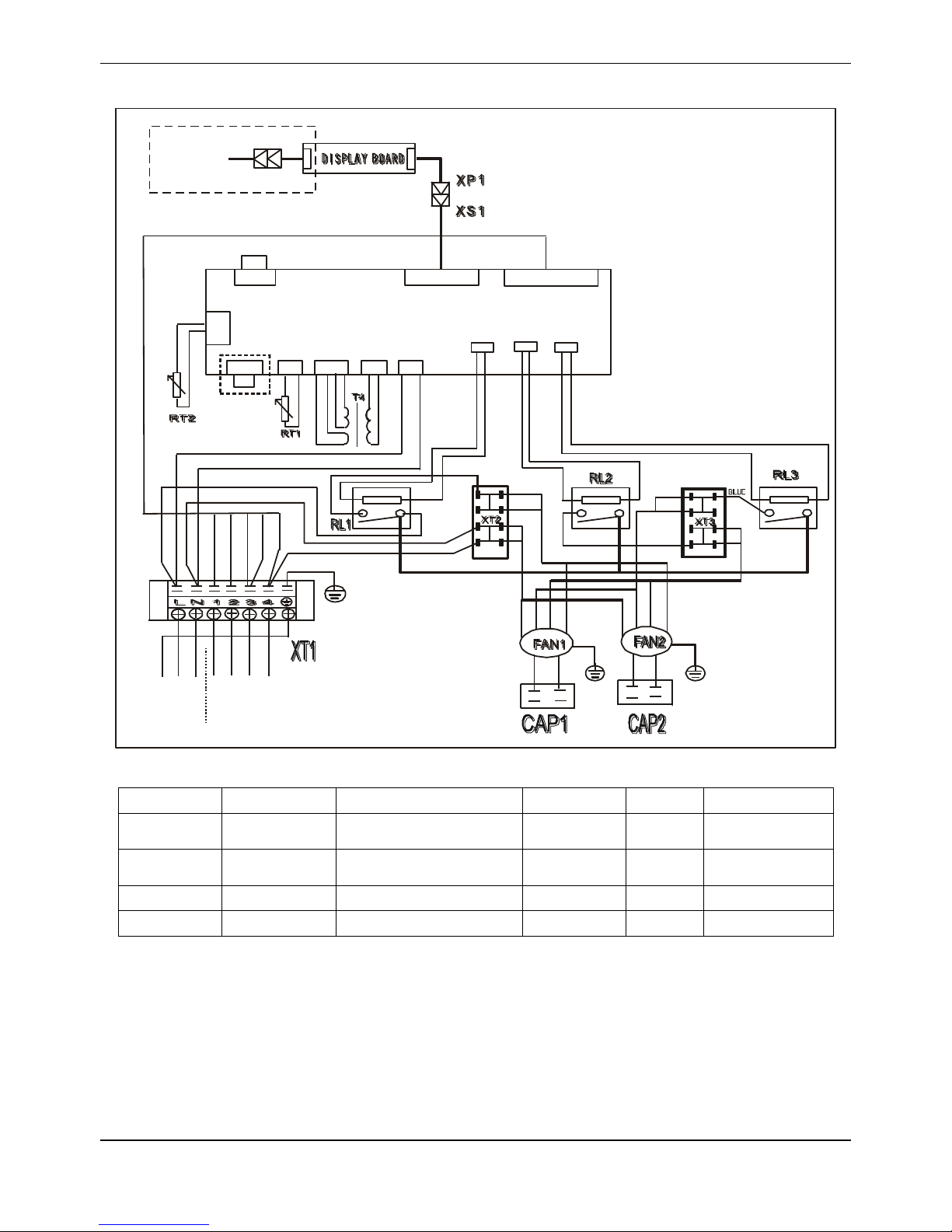
6.3 MTA-76HRN1, MTA-96HRN1, MHB-76HRN1, MHB-96HRN1
INDOOR POWER
Y
E
L
L
O
W
G
R
E
E
N
B
R
O
W
N
B
L
U
E
R
E
D
B
L
U
E
R
E
D
WHITE
RED
RED
WHITE
SLOW
HIGH
LOW
R
E
D
TO OUTDOOR
B
L
A
C
K
Y
E
L
L
O
W
R
E
D
WHITE
B
L
U
E
Y/G
B
L
A
C
K
R
E
D
WHITE
B
L
U
E
Y/G
MAIN C ONTROL BO ARD
WHITE
(GRAY)
WHITE
(GRAY)
CN20 CN7 CN3 CN2 CN1
CN8
CN11 CN10 CN15
TO WIRE
CONTROLLER
RL1 RL2 RL3
BLUE
RED
B
R
O
W
N
B
R
O
W
N
B
R
O
W
N
B
R
O
W
N
B
R
O
W
N
B
R
O
W
N
Y
E
L
L
O
W
B
L
A
C
K
R
E
D
B
L
U
E
Y
E
L
L
O
W
Y/G
WHITE
RED
BLUE
B
L
U
E
B
L
U
E
N-LINE
BLACK
BLACK
YELLOW
BLACK
Item
Name
Item
Name
Item
Name
CAP1-CAP2
Indoor fan cap
CN1-3,CN7,CN8,
CN10,CN11,CN15,CN20
PCB sockets
T4
Transformer
FAN1-FAN2
Indoor fan
RT1
Room temp.
sensor
RT2
Pipe temp.
sensor
XP1
Connector
XS1
Connector
XT1
7-way terminal
XT2,XT3
Mid terminal
RL1,RL2,RL3
Relay
-
-
Page 20
R410A 50Hz Tropical Split AC MCAC-UTSM-2012-12
20
6.4 MTA-120HRN1
INDOOR POWER
B
L
A
C
K
Y
E
L
L
O
W
Y
E
L
L
O
W
G
R
E
E
N
B
R
O
W
N
B
L
U
E
R
E
D
B
L
U
E
R
E
D
R
E
D
WHITE
RED RED
WHITE
WHITE
(GRAY)
WHITE
SLOW
HIGH
LOW
BLUE
BLUE
RED
TO OUTDOOR
Y/G
B
L
A
C
K
Y
E
L
L
O
W
R
E
D
WHITE
B
L
U
E
Y/G
B
L
A
C
K
R
E
D
WHITE
B
L
U
E
Y/G
MAIN CONTROL BOARD
WHITE
(GRAY)
WHITE
(GRAY)
CN20 CN7 CN3 CN2 CN1
CN8
CN11 CN10 CN15
TO WIRE
CONTROLLER
RL1 RL2 RL3
BLUE
RED
B
R
O
W
N
B
R
O
W
N
B
R
O
W
N
B
R
O
W
N
B
R
O
W
N
B
R
O
W
N
B
L
U
E
Y
E
L
L
O
W
B
L
A
C
K
B
L
A
C
K
R
E
D
R
E
D
B
L
U
E
B
L
U
E
Y
E
L
L
O
W
Y
E
L
L
O
W
Y/G
WHITE
R
E
D
BLACK
Item
Name
Item
Name
Item
Name
CAP1-CAP3
Indoor fan cap
CN1-3,CN7,CN8,
CN10,CN11,CN15,CN20
PCB sockets
T4
Transformer
FAN1-FAN3
Indoor fan
RT1
Room temp.
sensor
RT2
Pipe temp.
sensor
XP1
Connector
XS1
Connector
XT1
7-way terminal
XT2,XT3
Mid terminal
RL1,RL2,RL3
Relay
-
-
Page 21
MCAC-UTSM-2012-12 R410A 50Hz Tropical Split AC
21
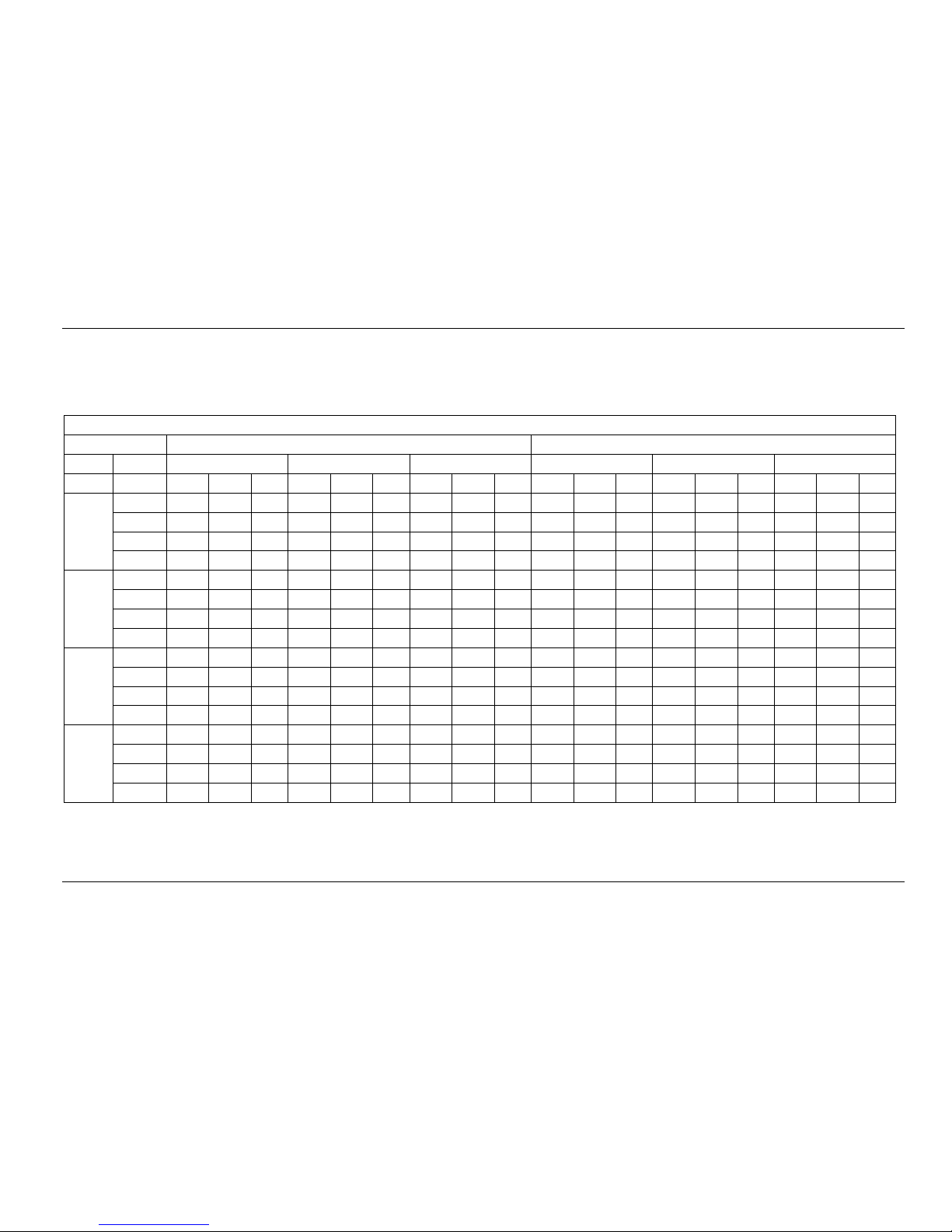
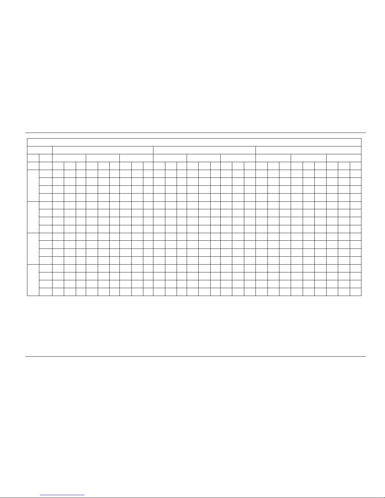
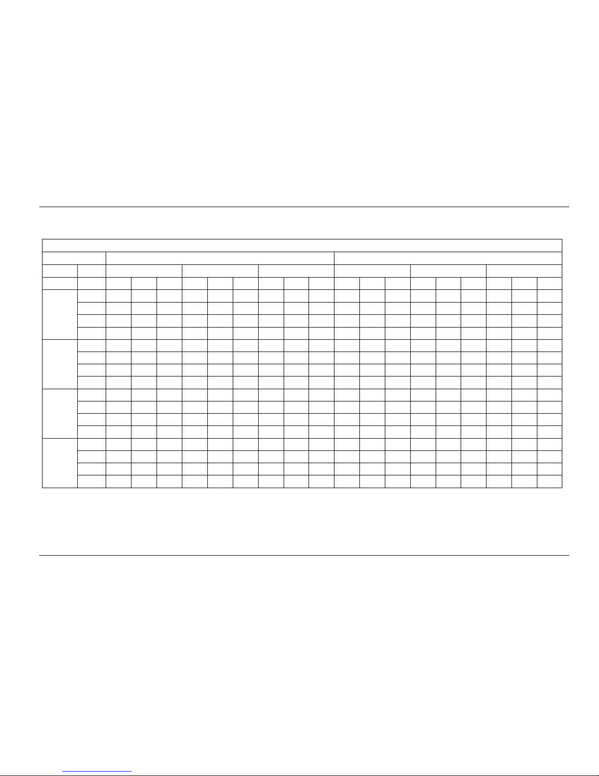
7. Capacity Table
7.1 Cooling:
7.1.1 MTA-76CRN1
Gross Cooling Capacity (kW)
Outdoor DB(°C)
29.40
35.00
Indoor
WB(°C)
16.10
19.40
22.80
16.10
19.40
22.80
CFM
DB(°C)
TGC
SHC
PI
TGC
SHC
PI
TGC
SHC
PI
TGC
SHC
PI
TGC
SHC
PI
TGC
SHC
PI
2000
23.9
19.5
15.2
6.56
21.9
12.4
6.76
23.3
5.4
6.89
18.7
15.3
6.99
20.8
11.7
7.22
22.0
5.1
7.36
26.7
20.2
17.4
6.58
22.4
14.5
6.78
23.8
10.3
6.91
19.1
17.4
7.01
21.2
13.7
7.24
22.5
9.7
7.38
29.4
20.9
19.0
6.60
22.8
18.7
6.80
24.3
14.4
6.93
19.5
18.7
7.03
21.6
17.7
7.26
22.9
13.6
7.40
32.2
21.6
21.2
6.61
23.3
21.2
6.81
24.7
18.2
6.94
19.9
19.5
7.05
22.0
20.0
7.28
23.4
17.2
7.42
2300
23.9
20.6
16.5
6.76
22.5
13.0
6.96
23.9
5.6
7.09
19.7
16.6
7.19
21.4
12.4
7.42
22.6
5.3
7.56
26.7
21.3
18.5
6.78
23.0
16.3
6.98
24.4
10.7
7.11
20.1
18.6
7.21
21.8
15.5
7.44
23.1
10.1
7.58
29.4
22.0
20.4
6.80
23.5
19.7
7.00
24.9
15.2
7.13
20.5
20.1
7.23
22.2
18.7
7.46
23.6
14.4
7.60
32.2
22.8
21.7
6.81
23.9
22.2
7.01
25.4
18.9
7.15
20.9
20.9
7.25
22.7
21.0
7.47
24.0
17.9
7.62
2500
23.9
21.1
18.3
7.00
23.0
14.4
7.33
24.4
6.3
7.33
20.2
18.5
7.43
21.9
13.7
7.48
23.1
6.0
7.80
26.7
21.8
20.8
7.02
23.5
18.1
7.22
24.9
11.9
7.35
20.6
20.6
7.45
22.0
17.2
7.50
23.6
11.3
7.82
29.4
22.6
21.9
7.04
24.0
22.0
7.24
25.4
16.8
7.37
21.0
21.0
7.47
22.7
20.9
7.70
24.1
15.9
7.84
32.2
23.4
22.9
7.06
24.4
22.2
7.26
25.9
21.1
7.39
21.4
21.4
7.49
23.2
21.1
7.72
24.6
20.0
7.86
2800
23.9
21.5
19.1
7.31
23.5
14.1
7.51
24.9
6.1
7.64
21.0
18.6
7.74
22.4
13.4
7.97
23.6
5.8
8.11
26.7
22.3
21.4
7.33
24.0
17.6
7.53
25.4
11.5
7.66
21.4
20.6
7.76
22.8
16.8
7.99
24.1
11.0
8.13
29.4
23.1
22.4
7.35
24.5
21.3
7.55
25.9
16.4
7.68
21.8
21.8
7.78
23.3
20.2
8.01
24.6
15.6
8.15
32.2
23.9
23.4
7.37
25.0
24.0
7.57
26.4
20.5
7.70
22.3
22.3
7.80
23.7
22.8
8.03
25.1
19.4
8.17
Page 22
R410A 50Hz Tropical Split AC MCAC-UTSM-2012-12
22
Gross Cooling Capacity (kW)
Outdoor DB(°C)
40.60
46.10
51.70
Indoor
WB(°C)
16.10
19.40
22.80
16.10
19.40
22.80
16.10
19.40
22.80
CFM
DB(°C)
TGC
SHC
PI
TGC
SHC
PI
TGC
SHC
PI
TGC
SHC
PI
TGC
SHC
PI
TGC
SHC
PI
TGC
SHC
PI
TGC
SHC
PI
TGC
SHC
PI
2000
23.9
17.3
14.2
7.94
18.9
10.7
8.18
20.1
4.6
8.33
15.8
13.0
8.13
17.3
9.8
8.39
18.5
4.3
8.64
15.5
12.7
8.51
16.8
9.5
8.87
17.9
4.1
9.12
26.7
17.6
16.0
7.96
19.2
12.5
8.20
20.5
8.8
8.35
16.1
14.7
8.15
17.6
11.4
8.41
18.8
8.1
8.66
15.8
14.4
8.53
17.1
11.1
8.89
18.2
7.9
9.14
29.4
18.0
17.3
7.98
19.6
16.1
8.22
20.9
12.5
8.37
16.5
15.8
8.17
18.0
14.7
8.43
19.2
11.4
8.68
16.2
15.5
8.55
17.5
14.3
8.91
18.6
11.1
9.16
32.2
18.3
18.0
8.00
20.0
18.2
8.24
21.4
15.7
8.39
16.8
16.5
8.19
18.3
16.7
8.45
19.6
14.4
8.70
16.5
16.2
8.57
17.8
16.2
8.93
19.0
14.0
9.19
2300
23.9
17.9
15.0
8.14
19.5
11.2
8.38
20.7
4.9
8.53
16.4
13.8
8.33
17.9
10.3
8.59
19.1
4.5
8.84
16.1
13.6
8.71
17.4
10.1
9.07
18.5
4.4
9.32
26.7
18.3
16.9
8.16
19.9
14.1
8.40
21.2
9.3
8.55
16.8
15.5
8.35
18.3
12.9
8.61
19.5
8.5
8.86
16.5
15.2
8.73
17.8
12.6
9.09
18.9
8.3
9.34
29.4
18.6
18.3
8.18
20.2
17.0
8.42
21.6
13.2
8.57
17.1
16.8
8.37
18.6
15.6
8.63
19.8
12.1
8.88
16.8
16.5
8.75
18.1
15.2
9.11
19.2
11.7
9.36
32.2
19.0
19.0
8.20
20.7
19.1
8.44
22.0
16.4
8.59
17.4
17.4
8.39
19.0
17.6
8.65
20.2
15.1
8.90
17.1
17.1
8.77
18.5
17.1
9.14
19.6
14.6
9.39
2500
23.9
18.4
16.9
7.84
20.0
12.5
8.23
21.2
5.5
8.23
16.9
15.5
8.57
18.4
11.5
8.83
19.6
5.1
9.08
16.6
15.3
8.95
17.9
11.2
9.31
19.0
4.9
9.56
26.7
18.8
18.8
7.86
20.4
15.7
8.10
21.7
10.4
8.25
17.3
17.3
8.59
18.8
14.4
8.85
20.0
9.5
9.10
17.0
17.0
8.97
18.3
14.0
9.33
19.4
9.3
9.58
29.4
19.1
19.1
7.88
20.8
19.0
8.12
22.1
14.6
8.27
17.6
17.6
8.61
19.1
17.5
8.87
20.3
13.5
9.12
17.3
17.3
8.99
18.6
17.1
9.35
19.7
13.1
9.60
32.2
19.5
19.5
7.90
21.2
19.2
8.14
22.5
18.3
8.29
17.9
17.9
8.63
19.5
17.7
8.89
20.8
16.9
9.15
17.6
17.6
9.01
19.0
17.3
9.38
20.1
16.4
9.63
2800
23.9
18.9
16.7
8.69
20.4
12.2
8.93
21.7
5.3
9.08
17.4
15.4
8.88
18.9
11.3
9.14
20.0
4.9
9.39
17.1
15.1
9.26
18.4
11.0
9.62
19.5
4.8
9.87
26.7
19.3
18.5
8.71
20.9
15.3
8.95
22.2
10.1
9.10
17.8
17.1
8.90
19.3
14.2
9.16
20.5
9.3
9.41
17.5
16.8
9.28
18.8
13.8
9.64
19.9
9.0
9.89
29.4
19.6
19.6
8.73
21.3
18.5
8.97
22.6
14.3
9.12
18.1
18.1
8.92
19.6
17.1
9.18
20.9
13.2
9.43
17.8
17.8
9.30
19.1
16.6
9.66
20.3
12.8
9.91
32.2
20.0
20.0
8.75
21.7
20.9
8.99
23.0
17.9
9.15
18.5
18.5
8.94
20.0
19.3
9.21
21.3
16.5
9.46
18.2
18.2
9.33
19.5
18.8
9.69
20.7
16.0
9.94
Notes:
1. DB = Dry Bulb Temperature (°C), WB = Wet Bulb Temperature (°C)
2. TGC = Total Cooling Capacity (kW)
3. SHC = Sensible Heating Capacity (kW)
4. PI = Power Input (kW)
Page 23
MCAC-UTSM-2012-12 R410A 50Hz Tropical Split AC
23
7.1.2 MTA-76HRN1
Gross Cooling Capacity (kW)
Outdoor DB(°C)
29.40
35.00
Indoor
WB(°C)
16.10
19.40
22.80
16.10
19.40
22.80
CFM
DB(°C)
TGC
SHC
PI
TGC
SHC
PI
TGC
SHC
PI
TGC
SHC
PI
TGC
SHC
PI
TGC
SHC
PI
2000
23.9
19.2
15.0
6.38
21.6
12.2
6.58
23.0
5.3
6.71
18.4
15.1
6.81
20.5
11.6
7.04
21.7
5.0
7.18
26.7
19.9
17.2
6.40
22.1
14.3
6.60
23.5
10.1
6.73
18.8
17.1
6.83
20.9
13.5
7.06
22.2
9.6
7.20
29.4
20.6
18.7
6.42
22.5
18.5
6.62
23.9
14.3
6.75
19.2
18.4
6.85
21.3
17.5
7.08
22.6
13.5
7.22
32.2
21.3
20.9
6.43
23.0
20.9
6.63
24.4
18.0
6.76
19.6
19.2
6.86
21.7
19.7
7.10
23.1
17.0
7.24
2300
23.9
20.3
16.2
6.58
22.3
12.9
6.78
23.6
5.6
6.91
19.4
16.3
7.01
21.1
12.2
7.24
22.4
5.3
7.38
26.7
21.0
18.3
6.60
22.7
16.1
6.80
24.1
10.6
6.93
19.8
18.3
7.03
21.5
15.2
7.26
22.8
10.0
7.40
29.4
21.7
20.1
6.62
23.2
19.5
6.82
24.6
15.0
6.95
20.2
19.8
7.05
21.9
18.4
7.28
23.3
14.2
7.42
32.2
22.5
21.4
6.63
23.6
21.9
6.83
25.1
18.7
6.96
20.6
20.6
7.07
22.4
20.7
7.30
23.7
17.7
7.44
2500
23.9
20.8
18.1
6.82
22.7
14.2
7.15
24.1
6.2
7.15
19.9
18.3
7.25
21.6
13.5
7.48
22.8
5.9
7.62
26.7
21.5
20.5
6.84
23.2
17.8
7.04
24.6
11.8
7.17
20.3
20.3
7.27
22.0
16.9
7.50
23.3
11.1
7.64
29.4
22.3
21.6
6.86
23.7
21.7
7.06
25.1
16.6
7.19
20.7
20.7
7.29
22.4
20.6
7.52
23.8
15.7
7.66
32.2
23.0
22.6
6.87
24.1
21.9
7.08
25.6
20.8
7.21
21.1
21.1
7.31
22.9
20.8
7.54
24.2
19.7
7.68
2800
23.9
21.3
18.8
7.13
23.2
13.9
7.33
24.6
6.0
7.46
20.7
18.3
7.56
22.1
13.2
7.79
23.3
5.7
7.93
26.7
22.0
21.2
7.15
23.7
17.4
7.35
25.1
11.4
7.48
21.1
20.3
7.58
22.5
16.5
7.81
23.8
10.8
7.95
29.4
22.8
22.1
7.17
24.2
21.0
7.37
25.6
16.2
7.50
21.5
21.5
7.60
23.0
20.0
7.83
24.3
15.4
7.97
32.2
23.6
23.1
7.19
24.7
23.7
7.39
26.1
20.2
7.52
22.0
22.0
7.62
23.4
22.5
7.85
24.8
19.2
7.99
Page 24

R410A 50Hz Tropical Split AC MCAC-UTSM-2012-12
24
Gross Cooling Capacity (kW)
Outdoor DB(°C)
40.60
46.10
51.70
Indoor
WB(°C)
16.10
19.40
22.80
16.10
19.40
22.80
16.10
19.40
22.80
CFM
DB(°C)
TGC
SHC
PI
TGC
SHC
PI
TGC
SHC
PI
TGC
SHC
PI
TGC
SHC
PI
TGC
SHC
PI
TGC
SHC
PI
TGC
SHC
PI
TGC
SHC
PI
2000
23.9
17.2
14.1
8.01
18.7
10.6
8.25
20.0
4.6
8.40
15.7
12.9
8.20
17.2
9.7
8.46
18.4
4.2
8.71
15.2
12.5
8.76
16.5
9.3
9.12
17.6
4.1
9.37
26.7
17.5
15.9
8.03
19.1
12.4
8.27
20.4
8.8
8.42
16.0
14.6
8.22
17.5
11.3
8.48
18.7
8.1
8.73
15.5
14.1
8.78
16.8
10.9
9.14
17.9
7.7
9.39
29.4
17.9
17.2
8.05
19.5
16.0
8.29
20.8
12.4
8.44
16.3
15.7
8.24
17.9
14.6
8.50
19.1
11.4
8.75
15.8
15.2
8.80
17.2
14.1
9.16
18.3
10.9
9.41
32.2
18.2
17.9
8.07
19.9
18.1
8.31
21.2
15.6
8.46
16.7
16.3
8.26
18.2
16.6
8.52
19.5
14.3
8.77
16.1
15.8
8.82
17.5
15.9
9.19
18.6
13.7
9.44
2300
23.9
17.8
14.9
8.21
19.4
11.2
8.45
20.6
4.9
8.60
16.3
13.7
8.40
17.8
10.3
8.66
19.0
4.5
8.91
15.8
13.3
8.96
17.1
9.9
9.32
18.2
4.3
9.57
26.7
18.1
16.8
8.23
19.7
14.0
8.47
21.0
9.2
8.62
16.6
15.4
8.42
18.1
12.9
8.68
19.3
8.5
8.93
16.1
14.9
8.98
17.4
12.4
9.34
18.5
8.1
9.59
29.4
18.5
18.1
8.25
20.1
16.9
8.49
21.5
13.1
8.64
17.0
16.6
8.44
18.5
15.5
8.70
19.7
12.0
8.95
16.5
16.1
9.00
17.8
14.9
9.36
18.9
11.5
9.61
32.2
18.9
18.9
8.27
20.5
19.0
8.51
21.9
16.3
8.66
17.3
17.3
8.46
18.9
17.5
8.72
20.1
15.0
8.97
16.8
16.8
9.02
18.1
16.8
9.39
19.3
14.4
9.64
2500
23.9
18.3
16.8
7.91
19.8
12.4
8.30
21.1
5.5
8.30
16.8
15.4
8.64
18.3
11.4
8.90
19.5
5.0
9.15
16.3
15.0
9.20
17.6
11.0
9.56
18.7
4.8
9.81
26.7
18.6
18.6
7.93
20.2
15.6
8.17
21.5
10.3
8.32
17.1
17.1
8.66
18.6
14.3
8.92
19.8
9.5
9.17
16.6
16.6
9.22
17.9
13.8
9.58
19.0
9.1
9.83
29.4
19.0
19.0
7.95
20.6
18.9
8.19
22.0
14.6
8.34
17.5
17.5
8.68
19.0
17.4
8.94
20.2
13.4
9.19
17.0
17.0
9.24
18.3
16.8
9.60
19.4
12.9
9.85
32.2
19.4
19.4
7.97
21.1
19.1
8.21
22.4
18.2
8.36
17.8
17.8
8.70
19.4
17.6
8.96
20.6
16.8
9.22
17.3
17.3
9.27
18.7
17.0
9.63
19.8
16.1
9.88
2800
23.9
18.8
16.6
8.76
20.3
12.2
9.00
21.6
5.3
9.15
17.3
15.3
8.95
18.8
11.2
9.21
19.9
4.9
9.46
16.8
14.9
9.51
18.1
10.8
9.87
19.2
4.7
10.11
26.7
19.1
18.4
8.78
20.7
15.3
9.02
22.0
10.0
9.17
17.6
17.0
8.97
19.1
14.1
9.23
20.3
9.2
9.48
17.1
16.5
9.53
18.4
13.6
9.89
19.5
8.9
10.14
29.4
19.5
19.5
8.80
21.2
18.4
9.04
22.5
14.2
9.19
18.0
18.0
8.99
19.5
17.0
9.25
20.7
13.1
9.50
17.5
17.5
9.55
18.8
16.4
9.91
19.9
12.6
10.17
32.2
19.9
19.9
8.82
21.6
20.7
9.07
22.9
17.8
9.22
18.4
18.4
9.01
19.9
19.1
9.28
21.2
16.4
9.53
17.8
17.8
9.58
19.2
18.4
9.94
20.3
15.8
10.19
Notes:
1. DB = Dry Bulb Temperature (°C), WB = Wet Bulb Temperature (°C)
2. TGC = Total Cooling Capacity (kW)
3. SHC = Sensible Heating Capacity (kW)
4. PI = Power Input (kW)
Page 25

MCAC-UTSM-2012-12 R410A 50Hz Tropical Split AC
25
7.1.3 MTA-96CRN1
Gross Cooling Capacity (kW)
Outdoor DB(°C)
29.40
35.00
Indoor
WB(°C)
16.10
19.40
22.80
16.10
19.40
22.80
CFM
DB(°C)
TGC
SHC
PI
TGC
SHC
PI
TGC
SHC
PI
TGC
SHC
PI
TGC
SHC
PI
TGC
SHC
PI
2440
23.9
25.3
19.8
8.50
27.8
15.7
8.70
29.2
6.7
8.83
24.6
20.2
8.93
26.6
15.1
9.16
27.9
6.4
9.30
26.7
26.2
22.6
8.52
28.4
18.4
8.72
29.8
12.8
8.85
25.1
22.8
8.95
27.2
17.6
9.18
28.5
12.3
9.32
29.4
27.1
24.7
8.54
28.9
23.7
8.74
30.4
18.1
8.87
25.6
24.6
8.97
27.7
22.7
9.20
29.0
17.3
9.34
32.2
28.1
27.5
8.56
29.5
26.8
8.76
31.0
22.8
8.89
26.1
25.6
8.99
28.3
25.7
9.23
29.6
21.8
9.37
2740
23.9
26.4
21.1
8.70
28.4
16.4
8.90
29.8
7.0
9.03
25.6
21.5
9.13
27.3
15.8
9.36
28.5
6.7
9.50
26.7
27.3
23.7
8.72
29.0
20.6
8.92
30.4
13.3
9.05
26.1
24.2
9.15
27.8
19.7
9.38
29.1
12.8
9.52
29.4
28.3
26.2
8.74
29.6
24.9
8.94
31.0
18.9
9.07
26.6
26.1
9.17
28.4
23.8
9.40
29.7
18.1
9.54
32.2
29.2
27.9
8.76
30.2
27.9
8.96
31.6
23.6
9.10
27.2
27.2
9.20
28.9
26.8
9.43
30.3
22.6
9.57
3000
23.9
26.9
23.4
8.94
28.9
18.1
9.27
30.3
7.8
9.27
26.1
23.9
9.37
27.7
17.3
9.55
29.0
7.5
9.74
26.7
27.8
26.5
8.96
29.5
22.7
9.16
30.9
14.8
9.29
26.6
26.6
9.39
28.0
21.8
9.60
29.6
14.2
9.76
29.4
28.8
27.9
8.98
30.1
27.6
9.18
31.5
20.9
9.31
27.1
27.1
9.41
28.9
26.5
9.64
30.2
20.0
9.78
32.2
29.8
29.2
9.00
30.7
27.9
9.21
32.1
26.1
9.34
27.7
27.7
9.44
29.4
26.8
9.67
30.8
25.0
9.81
3240
23.9
27.3
24.2
9.25
29.4
17.6
9.45
30.8
7.5
9.58
26.9
23.8
9.68
28.2
16.9
9.91
29.5
7.2
10.04
26.7
28.3
27.2
9.27
30.0
22.1
9.47
31.4
14.3
9.60
27.4
26.3
9.70
28.8
21.2
9.93
30.1
13.7
10.07
29.4
29.3
28.4
9.29
30.6
26.6
9.49
32.0
20.3
9.62
27.9
27.9
9.72
29.4
25.5
9.95
30.7
19.4
10.10
32.2
30.3
29.7
9.32
31.2
30.0
9.52
32.7
25.3
9.65
28.5
28.5
9.75
30.0
28.8
9.98
31.3
24.3
10.12
Page 26

R410A 50Hz Tropical Split AC MCAC-UTSM-2012-12
26
Gross Cooling Capacity (kW)
Outdoor DB(°C)
40.60
46.10
51.70
Indoor
WB(°C)
16.10
19.40
22.80
16.10
19.40
22.80
16.10
19.40
22.80
CFM
DB(°C)
TGC
SHC
PI
TGC
SHC
PI
TGC
SHC
PI
TGC
SHC
PI
TGC
SHC
PI
TGC
SHC
PI
TGC
SHC
PI
TGC
SHC
PI
TGC
SHC
PI
2440
23.9
22.0
18.0
10.63
23.6
13.3
10.87
24.8
5.7
11.02
20.5
16.8
10.82
22.0
12.4
11.08
23.2
5.4
11.33
20.0
16.4
11.42
21.3
12.0
11.78
22.4
5.2
12.03
26.7
22.4
20.4
10.66
24.0
15.6
10.90
25.3
10.9
11.05
20.9
19.0
10.85
22.4
14.5
11.11
23.6
10.2
11.36
20.4
18.6
11.45
21.7
14.1
11.81
22.8
9.8
12.06
29.4
22.9
22.0
10.69
24.5
20.1
10.93
25.8
15.4
11.08
21.3
20.5
10.88
22.9
18.8
11.14
24.1
14.3
11.39
20.8
20.0
11.48
22.2
18.2
11.84
23.3
13.9
12.09
32.2
23.3
22.9
10.71
25.0
22.7
10.95
26.4
19.4
11.11
21.8
21.3
10.90
23.3
21.2
11.17
24.6
18.1
11.42
21.3
20.8
11.51
22.6
20.6
11.87
23.8
17.5
12.12
2740
23.9
22.6
19.0
10.83
24.2
14.0
11.07
25.4
6.0
11.22
21.1
17.8
11.02
22.6
13.1
11.28
23.8
5.6
11.53
20.6
17.3
11.62
21.9
12.7
11.98
23.0
5.4
12.23
26.7
23.1
21.3
10.86
24.7
17.5
11.10
26.0
11.4
11.25
21.6
20.0
11.05
23.1
16.3
11.31
24.3
10.6
11.56
21.1
19.5
11.65
22.4
15.9
12.01
23.5
10.3
12.26
29.4
23.5
23.1
10.89
25.1
21.1
11.13
26.5
16.1
11.28
22.0
21.6
11.08
23.5
19.8
11.34
24.7
15.1
11.59
21.5
21.1
11.68
22.8
19.2
12.04
23.9
14.6
12.29
32.2
24.0
24.0
10.91
25.6
23.7
11.16
27.0
20.1
11.31
22.4
22.4
11.11
24.0
22.2
11.37
25.2
18.8
11.62
21.9
21.9
11.71
23.3
21.5
12.07
24.4
18.2
12.32
3000
23.9
23.1
21.2
11.07
24.7
15.4
11.46
25.9
6.7
11.46
21.6
19.8
11.26
23.1
14.4
11.52
24.3
6.3
11.77
21.1
19.4
11.86
22.4
14.0
12.22
23.5
6.1
12.47
26.7
23.6
23.6
11.10
25.2
19.3
11.34
26.5
12.7
11.49
22.1
22.1
11.29
23.6
18.1
11.55
24.8
11.8
11.80
21.6
21.6
11.89
22.9
17.6
12.25
24.0
11.5
12.50
29.4
24.0
24.0
11.13
25.7
23.5
11.37
27.0
17.9
11.52
22.5
22.5
11.32
24.0
22.0
11.58
25.2
16.7
11.83
22.0
22.0
11.92
23.3
21.4
12.28
24.4
16.2
12.53
32.2
24.5
24.5
11.16
26.2
23.8
11.40
27.5
22.4
11.55
22.9
22.9
11.35
24.5
22.3
11.61
25.7
20.9
11.86
22.4
22.4
11.95
23.8
21.6
12.31
24.9
20.3
12.56
3240
23.9
23.6
20.9
11.38
25.1
15.1
11.62
26.4
6.5
11.77
22.1
19.6
11.57
23.6
14.1
11.83
24.8
6.1
12.08
21.6
19.1
12.17
22.9
13.7
12.53
24.0
5.9
12.78
26.7
24.1
23.1
11.41
25.7
18.9
11.65
27.0
12.3
11.80
22.6
21.7
11.60
24.1
17.7
11.86
25.3
11.5
12.11
22.1
21.2
12.20
23.4
17.2
12.56
24.5
11.1
12.81
29.4
24.5
24.5
11.44
26.2
22.8
11.68
27.5
17.4
11.83
23.0
23.0
11.63
24.5
21.3
11.89
25.8
16.3
12.14
22.5
22.5
12.23
23.8
20.7
12.59
24.9
15.8
12.84
32.2
25.0
25.0
11.47
26.7
25.7
11.71
28.0
21.7
11.86
23.5
23.5
11.66
25.0
24.1
11.92
26.3
20.4
12.17
22.9
22.9
12.26
24.3
23.4
12.62
25.4
19.7
12.87
Notes:
1. DB = Dry Bulb Temperature (°C), WB = Wet Bulb Temperature (°C)
2. TGC = Total Cooling Capacity (kW)
3. SHC = Sensible Heating Capacity (kW)
4. PI = Power Input (kW)
Page 27

MCAC-UTSM-2012-12 R410A 50Hz Tropical Split AC
27
7.1.4 MTA-96HRN1
Gross Cooling Capacity (kW)
Outdoor DB(°C)
29.40
35.00
Indoor
WB(°C)
16.10
19.40
22.80
16.10
19.40
22.80
CFM
DB(°C)
TGC
SHC
PI
TGC
SHC
PI
TGC
SHC
PI
TGC
SHC
PI
TGC
SHC
PI
TGC
SHC
PI
2440
23.9
24.9
19.4
8.47
27.4
15.5
8.67
28.8
6.6
8.80
24.2
19.8
8.90
26.2
14.8
9.13
27.5
6.3
9.27
26.7
25.8
22.2
8.49
27.9
18.1
8.69
29.3
12.6
8.82
24.7
22.4
8.92
26.7
17.3
9.15
28.0
12.1
9.29
29.4
26.7
24.2
8.51
28.5
23.4
8.71
29.9
17.8
8.84
25.1
24.2
8.94
27.3
22.3
9.17
28.6
17.0
9.31
32.2
27.6
27.0
8.53
29.1
26.4
8.73
30.5
22.4
8.86
25.6
25.1
8.96
27.8
25.3
9.20
29.2
21.4
9.34
2740
23.9
25.9
20.8
8.67
28.0
16.2
8.87
29.4
6.9
9.00
25.1
21.1
9.10
26.8
15.5
9.33
28.1
6.6
9.47
26.7
26.9
23.3
8.69
28.6
20.2
8.89
30.0
13.1
9.02
25.7
23.8
9.12
27.4
19.4
9.35
28.7
12.6
9.49
29.4
27.8
25.7
8.71
29.1
24.5
8.91
30.5
18.6
9.04
26.2
25.7
9.14
27.9
23.4
9.37
29.2
17.8
9.51
32.2
28.8
27.4
8.73
29.7
27.5
8.93
31.2
23.3
9.07
26.7
26.7
9.17
28.5
26.3
9.40
29.8
22.2
9.54
3000
23.9
26.4
23.0
8.91
28.5
17.8
9.24
29.9
7.7
9.24
25.6
23.5
9.34
27.3
17.1
9.57
28.6
7.4
9.71
26.7
27.4
26.0
8.93
29.1
22.3
9.13
30.5
14.6
9.26
26.2
26.2
9.36
28.0
21.4
9.60
29.2
13.9
9.73
29.4
28.3
27.5
8.95
29.6
27.2
9.15
31.1
20.6
9.28
26.7
26.7
9.38
28.4
26.1
9.61
29.7
19.7
9.75
32.2
29.3
28.7
8.97
30.2
27.5
9.18
31.7
25.8
9.31
27.2
27.2
9.41
29.0
26.3
9.64
30.3
24.7
9.78
3240
23.9
26.9
23.8
9.22
29.0
17.3
9.42
30.3
7.4
9.55
26.4
23.4
9.65
27.8
16.6
9.88
29.1
7.1
10.01
26.7
27.9
26.8
9.24
29.6
21.7
9.44
31.0
14.1
9.57
27.0
25.9
9.67
28.4
20.8
9.90
29.7
13.5
10.04
29.4
28.8
28.0
9.26
30.1
26.2
9.46
31.6
20.0
9.59
27.5
27.5
9.69
28.9
25.1
9.92
30.2
19.1
10.07
32.2
29.8
29.2
9.29
30.7
29.6
9.49
32.2
25.0
9.62
28.0
28.0
9.72
29.5
28.4
9.95
30.8
23.9
10.09
Page 28
R410A 50Hz Tropical Split AC MCAC-UTSM-2012-12
28
Gross Cooling Capacity (kW)
Outdoor DB(°C)
40.60
46.10
51.70
Indoor
WB(°C)
16.10
19.40
22.80
16.10
19.40
22.80
16.10
19.40
22.80
CFM
DB(°C)
TGC
SHC
PI
TGC
SHC
PI
TGC
SHC
PI
TGC
SHC
PI
TGC
SHC
PI
TGC
SHC
PI
TGC
SHC
PI
TGC
SHC
PI
TGC
SHC
PI
2440
23.9
22.0
18.0
10.83
23.5
13.3
11.07
24.8
5.7
11.22
20.5
16.8
11.02
22.0
12.4
11.28
23.1
5.3
11.53
19.4
15.9
11.52
20.7
11.7
11.88
21.8
5.0
12.13
26.7
22.4
20.4
10.86
24.0
15.5
11.10
25.3
10.9
11.25
20.9
19.0
11.05
22.4
14.5
11.31
23.6
10.2
11.56
19.8
18.0
11.55
21.1
13.7
11.91
22.2
9.6
12.16
29.4
22.8
22.0
10.89
24.5
20.1
11.13
25.8
15.4
11.28
21.3
20.5
11.08
22.8
18.7
11.34
24.1
14.3
11.59
20.2
19.4
11.58
21.5
17.6
11.94
22.7
13.5
12.19
32.2
23.3
22.8
10.91
25.0
22.7
11.16
26.3
19.4
11.31
21.7
21.3
11.11
23.3
21.2
11.37
24.6
18.1
11.62
20.6
20.2
11.61
22.0
20.0
11.97
23.1
17.0
12.22
2740
23.9
22.6
19.0
11.03
24.1
14.0
11.27
25.4
6.0
11.42
21.1
17.7
11.22
22.6
13.0
11.48
23.7
5.6
11.73
20.0
16.8
11.72
21.3
12.3
12.08
22.4
5.3
12.33
26.7
23.0
21.3
11.06
24.6
17.5
11.30
25.9
11.4
11.45
21.5
19.9
11.25
23.0
16.3
11.51
24.2
10.6
11.76
20.4
18.9
11.75
21.7
15.4
12.11
22.8
10.0
12.36
29.4
23.5
23.0
11.09
25.1
21.1
11.33
26.4
16.1
11.48
22.0
21.5
11.28
23.5
19.7
11.54
24.7
15.1
11.79
20.8
20.4
11.78
22.2
18.6
12.14
23.3
14.2
12.39
32.2
24.0
24.0
11.12
25.6
23.7
11.36
27.0
20.1
11.51
22.4
22.4
11.31
24.0
22.2
11.57
25.2
18.8
11.82
21.3
21.3
11.81
22.6
20.9
12.17
23.8
17.7
12.42
3000
23.9
23.1
21.2
11.27
24.6
15.4
11.66
25.9
6.7
11.66
21.6
19.8
11.46
23.1
14.4
11.72
24.2
6.3
11.97
20.5
18.8
11.96
21.8
13.6
12.32
22.9
5.9
12.57
26.7
23.5
23.5
11.30
25.1
19.3
11.54
26.4
12.6
11.69
22.0
22.0
11.49
23.3
18.1
11.75
24.7
11.8
12.00
20.9
20.9
11.99
22.2
17.1
12.35
23.3
11.2
12.60
29.4
24.0
24.0
11.33
25.6
23.5
11.57
26.9
17.8
11.72
22.5
22.5
11.52
24.0
22.0
11.78
25.2
16.7
12.03
21.3
21.3
12.02
22.7
20.8
12.38
23.8
15.8
12.63
32.2
24.5
24.5
11.36
26.1
23.8
11.60
27.5
22.3
11.75
22.9
22.9
11.55
24.5
22.2
11.81
25.7
20.9
12.06
21.8
21.8
12.05
23.1
21.0
12.41
24.3
19.7
12.66
3240
23.9
23.5
20.8
11.58
25.1
15.0
11.82
26.4
6.5
11.97
22.1
19.5
11.77
23.5
14.1
12.03
24.7
6.1
12.28
21.0
18.6
12.27
22.3
13.3
12.63
23.4
5.7
12.88
26.7
24.0
23.1
11.61
25.6
18.8
11.85
26.9
12.2
12.00
22.5
21.7
11.80
24.0
17.7
12.06
25.2
11.5
12.31
21.4
20.6
12.30
22.7
16.7
12.66
23.8
10.8
12.91
29.4
24.5
24.5
11.64
26.1
22.7
11.88
27.5
17.4
12.03
23.0
23.0
11.83
24.5
21.3
12.09
25.7
16.3
12.34
21.9
21.9
12.33
23.2
20.2
12.69
24.3
15.4
12.94
32.2
25.0
25.0
11.67
26.7
25.6
11.91
28.0
21.7
12.06
23.4
23.4
11.86
25.0
24.0
12.12
26.2
20.3
12.37
22.3
22.3
12.36
23.6
22.7
12.72
24.8
19.2
12.97
Notes:
1. DB = Dry Bulb Temperature (°C), WB = Wet Bulb Temperature (°C)
2. TGC = Total Cooling Capacity (kW)
3. SHC = Sensible Heating Capacity (kW)
4. PI = Power Input (kW)
Page 29

MCAC-UTSM-2012-12 R410A 50Hz Tropical Split AC
29
7.1.5 MTA-120CRN1
Gross Cooling Capacity (kW)
Outdoor DB(°C)
29.40
35.00
Indoor
WB(°C)
16.10
19.40
22.80
16.10
19.40
22.80
CFM
DB(°C)
TGC
SHC
PI
TGC
SHC
PI
TGC
SHC
PI
TGC
SHC
PI
TGC
SHC
PI
TGC
SHC
PI
3200
23.9
32.0
25.0
10.99
34.6
19.5
11.19
36.0
8.3
11.32
31.4
25.7
11.42
33.4
18.9
11.65
34.7
8.0
11.79
26.7
33.1
28.5
11.02
35.3
22.8
11.22
36.7
15.8
11.35
32.0
29.1
11.45
34.1
22.1
11.68
35.4
15.3
11.82
29.4
34.3
31.1
11.05
36.0
29.5
11.25
37.4
22.3
11.38
32.6
31.4
11.48
34.8
28.5
11.71
36.1
21.5
11.85
32.2
35.5
34.8
11.08
36.7
33.4
11.28
38.2
28.1
11.41
33.3
32.6
11.51
35.5
32.2
11.74
36.8
27.1
11.88
3500
23.9
33.0
26.4
11.19
35.2
20.3
11.39
36.6
8.6
11.52
32.4
27.2
11.62
34.0
19.7
11.85
35.3
8.3
11.99
26.7
34.2
29.7
11.22
35.9
25.5
11.42
37.3
16.4
11.55
33.0
30.6
11.65
34.7
24.6
11.88
36.0
15.8
12.02
29.4
35.4
32.8
11.25
36.6
30.8
11.45
38.0
23.2
11.58
33.7
33.0
11.68
35.4
29.7
11.91
36.7
22.4
12.05
32.2
36.6
34.9
11.28
37.4
34.6
11.48
38.8
29.0
11.61
34.3
34.3
11.71
36.1
33.4
11.94
37.5
28.0
12.08
3750
23.9
33.5
29.2
11.43
35.7
22.3
11.76
37.1
9.6
11.76
32.8
30.1
11.86
34.5
21.6
11.98
35.8
9.3
12.23
26.7
34.7
33.0
11.46
36.4
28.0
11.66
37.8
18.1
11.79
33.5
33.5
11.89
35.0
27.1
12.00
36.5
17.5
12.26
29.4
35.9
34.9
11.49
37.1
34.1
11.69
38.6
25.5
11.82
34.2
34.2
11.92
35.9
32.9
12.15
37.2
24.7
12.29
32.2
37.2
36.4
11.52
37.9
34.4
11.72
39.3
32.0
11.85
34.9
34.9
11.95
36.6
33.3
12.18
38.0
30.9
12.32
4000
23.9
34.0
30.1
11.74
36.2
21.7
11.94
37.5
9.2
12.07
33.6
29.8
12.17
35.0
21.0
12.40
36.3
8.9
12.54
26.7
35.2
33.8
11.77
36.9
27.1
11.97
38.3
17.4
12.10
34.3
33.0
12.20
35.7
26.3
12.43
37.0
16.8
12.57
29.4
36.4
35.4
11.80
37.6
32.7
12.00
39.1
24.7
12.13
35.0
35.0
12.23
36.4
31.7
12.46
37.7
23.9
12.60
32.2
37.7
37.0
11.83
38.4
36.9
12.03
39.8
30.9
12.16
35.7
35.7
12.26
37.1
35.7
12.49
38.5
29.8
12.63
Page 30
R410A 50Hz Tropical Split AC MCAC-UTSM-2012-12
30
Gross Cooling Capacity (kW)
Outdoor DB(°C)
40.60
46.10
51.70
Indoor
WB(°C)
16.10
19.40
22.80
16.10
19.40
22.80
16.10
19.40
22.80
CFM
DB(°C)
TGC
SHC
PI
TGC
SHC
PI
TGC
SHC
PI
TGC
SHC
PI
TGC
SHC
PI
TGC
SHC
PI
TGC
SHC
PI
TGC
SHC
PI
TGC
SHC
PI
3200
23.9
28.3
23.2
12.33
29.9
16.9
12.57
31.1
7.2
12.72
26.8
22.0
12.52
28.3
16.0
12.78
29.5
6.8
13.03
26.5
21.8
14.01
27.8
15.7
14.37
28.9
6.7
14.62
26.7
28.9
26.2
12.36
30.5
19.7
12.60
31.8
13.7
12.75
27.4
24.9
12.55
28.9
18.7
12.81
30.1
13.0
13.06
27.1
24.6
14.05
28.4
18.4
14.41
29.5
12.7
14.66
29.4
29.4
28.3
12.39
31.1
25.5
12.63
32.4
19.3
12.78
27.9
26.8
12.58
29.4
24.1
12.84
30.7
18.3
13.09
27.6
26.6
14.09
28.9
23.7
14.45
30.1
17.9
14.70
32.2
30.0
29.4
12.42
31.7
28.8
12.66
33.0
24.3
12.81
28.5
27.9
12.61
30.0
27.3
12.87
31.3
23.0
13.13
28.2
27.6
14.12
29.5
26.8
14.48
30.7
22.6
14.73
3500
23.9
28.9
24.3
12.53
30.5
17.6
12.77
31.7
7.5
12.92
27.4
23.1
12.72
28.9
16.7
12.98
30.1
7.1
13.23
27.2
22.8
14.21
28.4
16.4
14.57
29.5
7.0
14.82
26.7
29.5
27.3
12.56
31.1
22.0
12.80
32.4
14.2
12.95
28.0
25.9
12.75
29.5
20.9
13.01
30.7
13.5
13.26
27.7
25.6
14.25
29.0
20.6
14.61
30.1
13.2
14.86
29.4
30.1
29.5
12.59
31.7
26.6
12.83
33.0
20.1
12.98
28.5
28.0
12.78
30.1
25.3
13.04
31.3
19.1
13.29
28.3
27.7
14.29
29.6
24.9
14.65
30.7
18.7
14.90
32.2
30.7
30.7
12.62
32.3
29.9
12.86
33.7
25.1
13.01
29.1
29.1
12.81
30.7
28.4
13.08
31.9
23.8
13.33
28.8
28.8
14.32
30.2
27.9
14.68
31.3
23.4
14.93
3750
23.9
29.4
27.0
12.23
31.0
19.4
12.62
32.2
8.4
12.62
27.9
25.6
12.96
29.4
18.4
13.22
30.6
7.9
13.47
27.6
25.4
14.45
28.9
18.1
14.81
30.0
7.8
15.06
26.7
30.0
30.0
12.26
31.6
24.3
12.50
32.9
15.7
12.65
28.5
28.5
12.99
30.0
23.1
13.25
31.2
14.9
13.50
28.2
28.2
14.49
29.5
22.7
14.85
30.6
14.6
15.10
29.4
30.6
30.6
12.29
32.2
29.6
12.53
33.5
22.2
12.68
29.0
29.0
13.02
30.6
28.1
13.28
31.8
21.1
13.53
28.8
28.8
14.53
30.1
27.6
14.89
31.2
20.7
15.14
32.2
31.2
31.2
12.32
32.9
29.9
12.56
34.2
27.8
12.71
29.6
29.6
13.06
31.2
28.4
13.32
32.4
26.4
13.57
29.3
29.3
14.56
30.7
27.9
14.92
31.8
25.9
15.18
4000
23.9
29.9
26.4
13.08
31.5
18.8
13.32
32.7
8.0
13.47
28.4
25.1
13.27
29.9
17.9
13.53
31.1
7.6
13.78
28.1
24.9
14.76
29.4
17.6
15.12
30.5
7.5
15.37
26.7
30.5
29.3
13.11
32.1
23.6
13.35
33.4
15.2
13.50
29.0
27.9
13.30
30.5
22.4
13.56
31.7
14.4
13.81
28.7
27.6
14.80
30.0
22.1
15.16
31.1
14.1
15.41
29.4
31.1
31.1
13.14
32.7
28.5
13.38
34.0
21.5
13.53
29.6
29.6
13.33
31.1
27.0
13.59
32.3
20.5
13.84
29.3
29.3
14.84
30.6
26.6
15.20
31.7
20.1
15.45
32.2
31.7
31.7
13.18
33.4
32.1
13.42
34.7
26.9
13.57
30.2
30.2
13.37
31.7
30.5
13.63
33.0
25.6
13.88
29.9
29.9
14.87
31.2
30.0
15.24
32.4
25.1
15.49
Notes:
1. DB = Dry Bulb Temperature (°C), WB = Wet Bulb Temperature (°C)
2. TGC = Total Cooling Capacity (kW)
3. SHC = Sensible Heating Capacity (kW)
4. PI = Power Input (kW)
Page 31

MCAC-UTSM-2012-12 R410A 50Hz Tropical Split AC
31
7.1.6 MTA-120HR
Gross Cooling Capacity (kW)
Outdoor DB(°C)
29.40
35.00
Indoor
WB(°C)
16.10
19.40
22.80
16.10
19.40
22.80
CFM
DB(°C)
TGC
SHC
PI
TGC
SHC
PI
TGC
SHC
PI
TGC
SHC
PI
TGC
SHC
PI
TGC
SHC
PI
3200
23.9
31.8
24.8
10.87
34.4
19.4
11.07
35.8
8.3
11.20
31.2
25.6
11.30
33.2
18.8
11.53
34.5
8.0
11.67
26.7
32.9
28.4
10.90
35.1
22.7
11.10
36.5
15.7
11.23
31.8
28.9
11.33
33.9
21.9
11.56
35.2
15.2
11.70
29.4
34.1
31.0
10.93
35.8
29.3
11.13
37.2
22.1
11.26
32.4
31.2
11.36
34.6
28.3
11.59
35.9
21.4
11.73
32.2
35.2
34.6
10.95
36.5
33.2
11.16
38.0
27.9
11.29
33.1
32.4
11.39
35.2
32.0
11.62
36.6
26.9
11.76
3500
23.9
32.9
26.3
11.07
35.0
20.2
11.27
36.4
8.6
11.40
32.2
27.0
11.50
33.8
19.6
11.73
35.1
8.3
11.87
26.7
34.0
29.6
11.10
35.7
25.3
11.30
37.1
16.3
11.43
32.8
30.4
11.53
34.5
24.5
11.76
35.8
15.7
11.90
29.4
35.2
32.6
11.13
36.4
30.6
11.33
37.8
23.1
11.46
33.5
32.8
11.56
35.2
29.6
11.79
36.5
22.3
11.93
32.2
36.4
34.7
11.16
37.1
34.4
11.36
38.6
28.8
11.49
34.1
34.1
11.59
35.9
33.2
11.82
37.2
27.8
11.96
3750
23.9
33.3
29.0
11.31
35.5
22.2
11.64
36.9
9.5
11.64
32.6
30.0
11.74
34.3
21.4
11.97
35.6
9.2
12.11
26.7
34.5
32.9
11.34
36.2
27.8
11.54
37.6
18.0
11.67
33.3
33.3
11.77
35.0
26.9
12.00
36.3
17.4
12.14
29.4
35.7
34.7
11.37
36.9
33.9
11.57
38.4
25.4
11.70
34.0
34.0
11.80
35.7
32.8
12.03
37.0
24.5
12.17
32.2
37.0
36.2
11.40
37.7
34.2
11.60
39.1
31.8
11.73
34.6
34.6
11.83
36.4
33.1
12.06
37.8
30.7
12.20
4000
23.9
33.8
29.9
11.62
36.0
21.5
11.82
37.4
9.2
11.95
33.4
29.6
12.05
34.8
20.8
12.28
36.1
8.8
12.42
26.7
35.0
33.7
11.65
36.7
27.0
11.85
38.1
17.3
11.98
34.1
32.8
12.08
35.5
26.1
12.31
36.8
16.7
12.45
29.4
36.2
35.2
11.68
37.4
32.6
11.88
38.9
24.6
12.01
34.8
34.8
12.11
36.2
31.5
12.34
37.5
23.8
12.48
32.2
37.5
36.8
11.71
38.2
36.7
11.91
39.6
30.7
12.04
35.5
35.5
12.14
36.9
35.5
12.37
38.3
29.7
12.51
Page 32

R410A 50Hz Tropical Split AC MCAC-UTSM-2012-12
32
Gross Cooling Capacity (kW)
Outdoor DB(°C)
40.60
46.10
51.70
Indoor
WB(°C)
16.10
19.40
22.80
16.10
19.40
22.80
16.10
19.40
22.80
CFM
DB(°C)
TGC
SHC
PI
TGC
SHC
PI
TGC
SHC
PI
TGC
SHC
PI
TGC
SHC
PI
TGC
SHC
PI
TGC
SHC
PI
TGC
SHC
PI
TGC
SHC
PI
3200
23.9
28.0
22.9
12.73
29.5
16.7
12.97
30.8
7.1
13.12
26.5
21.7
12.92
28.0
15.8
13.18
29.2
6.7
13.43
26.2
21.4
14.72
27.4
15.5
15.08
28.5
6.6
15.33
26.7
28.5
25.9
12.76
30.1
19.5
13.00
31.4
13.6
13.15
27.0
24.6
12.95
28.5
18.5
13.21
29.7
12.8
13.46
26.7
24.3
14.76
28.0
18.1
15.12
29.1
12.5
15.37
29.4
29.1
28.0
12.79
30.7
25.2
13.03
32.1
19.1
13.18
27.6
26.5
12.98
29.1
23.9
13.24
30.3
18.1
13.49
27.2
26.2
14.80
28.5
23.4
15.16
29.7
17.7
15.41
32.2
29.7
29.1
12.82
31.4
28.5
13.07
32.7
24.1
13.22
28.1
27.6
13.01
29.7
27.0
13.28
30.9
22.8
13.53
27.8
27.2
14.83
29.1
26.5
15.20
30.3
22.3
15.45
3500
23.9
28.6
24.0
12.93
30.2
17.4
13.17
31.4
7.4
13.32
27.1
22.8
13.12
28.6
16.5
13.38
29.8
7.0
13.63
26.8
22.5
14.92
28.0
16.2
15.28
29.1
6.9
15.53
26.7
29.2
27.0
12.96
30.8
21.8
13.20
32.1
14.1
13.35
27.7
25.6
13.15
29.2
20.7
13.41
30.4
13.3
13.66
27.3
25.3
14.96
28.6
20.3
15.32
29.7
13.0
15.57
29.4
29.7
29.2
12.99
31.4
26.4
13.23
32.7
19.9
13.38
28.2
27.7
13.18
29.7
25.0
13.44
31.0
18.9
13.69
27.9
27.3
15.00
29.2
24.5
15.36
30.3
18.5
15.61
32.2
30.3
30.3
13.02
32.0
29.6
13.27
33.4
24.9
13.42
28.8
28.8
13.22
30.3
28.1
13.48
31.6
23.6
13.73
28.4
28.4
15.03
29.8
27.6
15.40
30.9
23.1
15.65
3750
23.9
29.1
26.7
12.63
30.6
19.2
13.02
31.9
8.3
13.02
27.6
25.3
13.36
29.1
18.2
13.62
30.3
7.8
13.87
27.3
25.0
15.16
28.5
17.8
15.52
29.6
7.7
15.77
26.7
29.7
29.7
12.66
31.3
24.0
12.90
32.6
15.6
13.05
28.2
28.2
13.39
29.7
22.8
13.65
30.9
14.8
13.90
27.8
27.8
15.20
29.1
22.4
15.56
30.2
14.5
15.81
29.4
30.3
30.3
12.69
31.9
29.3
12.93
33.2
22.0
13.08
28.7
28.7
13.42
30.3
27.8
13.68
31.5
20.8
13.93
28.4
28.4
15.24
29.7
27.2
15.60
30.8
20.4
15.85
32.2
30.9
30.9
12.72
32.5
29.6
12.96
33.9
27.5
13.12
29.3
29.3
13.46
30.9
28.1
13.72
32.1
26.1
13.97
28.9
28.9
15.28
30.3
27.5
15.64
31.4
25.6
15.89
4000
23.9
29.6
26.2
13.48
31.1
18.6
13.72
32.4
7.9
13.87
28.1
24.9
13.67
29.6
17.7
13.93
30.7
7.5
14.17
27.8
24.6
15.47
29.0
17.4
15.83
30.1
7.4
16.08
26.7
30.2
29.0
13.51
31.8
23.4
13.75
33.1
15.0
13.90
28.7
27.6
13.70
30.2
22.2
13.96
31.4
14.3
14.21
28.3
27.2
15.51
29.6
21.8
15.87
30.7
14.0
16.12
29.4
30.8
30.8
13.54
32.4
28.2
13.78
33.7
21.3
13.93
29.2
29.2
13.73
30.8
26.8
13.99
32.0
20.2
14.25
28.9
28.9
15.55
30.2
26.3
15.91
31.3
19.8
16.16
32.2
31.4
31.4
13.58
33.0
31.8
13.82
34.4
26.7
13.97
29.8
29.8
13.77
31.4
30.2
14.03
32.6
25.3
14.28
29.5
29.5
15.59
30.8
29.6
15.95
32.0
24.8
16.20
Notes:
1. DB = Dry Bulb Temperature (°C), WB = Wet Bulb Temperature (°C)
2. TGC = Total Cooling Capacity (kW)
3. SHC = Sensible Heating Capacity (kW)
4. PI = Power Input (kW)
Page 33

MCAC-UTSM-2012-12 R410A 50Hz Tropical Split AC
33
7.1.7 MTA-150CRN1
Gross Cooling Capacity (kW)
Outdoor DB(°C)
29.40
35.00
Indoor
WB(°C)
16.10
19.40
22.80
16.10
19.40
22.80
CFM
DB(°C)
TGC
SHC
PI
TGC
SHC
PI
TGC
SHC
PI
TGC
SHC
PI
TGC
SHC
PI
TGC
SHC
PI
4000
23.9
41.0
32.0
14.20
43.7
24.7
14.40
45.1
10.4
14.53
40.5
33.2
14.63
42.5
24.0
14.86
43.8
10.1
15.00
26.7
42.4
36.6
14.24
44.6
28.9
14.44
46.0
19.8
14.57
41.3
37.5
14.67
43.4
28.1
14.90
44.7
19.3
15.04
29.4
43.9
39.9
14.28
45.5
37.3
14.48
46.9
27.9
14.61
42.1
40.5
14.71
44.2
36.3
14.94
45.6
27.1
15.08
32.2
45.4
44.5
14.31
46.4
42.2
14.51
47.8
35.2
14.64
43.0
42.1
14.74
45.1
41.0
14.97
46.5
34.2
15.12
4300
23.9
42.0
33.6
14.40
44.3
25.6
14.60
45.7
10.8
14.73
41.5
34.8
14.83
43.1
24.9
14.99
44.4
10.5
15.20
26.7
43.5
37.8
14.44
45.2
32.1
14.64
46.6
20.4
14.77
42.3
39.2
14.87
44.0
31.2
15.01
45.3
19.9
15.24
29.4
45.0
41.7
14.48
46.1
38.7
14.68
47.5
29.0
14.81
43.1
42.3
14.91
44.9
37.7
15.03
46.2
28.2
15.28
32.2
46.6
44.4
14.51
47.0
43.5
14.71
48.5
36.2
14.84
44.0
44.0
14.94
45.8
42.4
15.05
47.1
35.2
15.32
4500
23.9
42.5
37.0
14.64
44.8
28.0
14.97
46.2
12.0
14.97
42.0
38.5
15.07
43.6
27.3
15.08
44.9
11.6
15.44
26.7
44.0
41.9
14.68
45.7
35.2
14.88
47.1
22.5
15.01
42.8
42.8
15.11
44.0
34.2
15.10
45.8
21.9
15.48
29.4
45.5
44.2
14.72
46.6
42.8
14.92
48.0
31.8
15.05
43.7
43.7
15.15
45.4
41.6
15.38
46.7
30.9
15.52
32.2
47.1
46.2
14.75
47.5
43.2
14.95
49.0
39.8
15.09
44.5
44.5
15.19
46.3
42.1
15.42
47.7
38.7
15.56
4800
23.9
43.0
38.0
14.95
45.3
27.1
15.15
46.7
11.4
15.28
42.7
37.8
15.38
44.1
26.4
15.61
45.4
11.1
15.75
26.7
44.5
42.8
14.99
46.2
34.0
15.19
47.6
21.6
15.32
43.6
41.9
15.42
45.0
33.1
15.65
46.3
21.0
15.79
29.4
46.1
44.7
15.03
47.1
41.0
15.23
48.6
30.7
15.36
44.5
44.5
15.46
45.9
39.9
15.69
47.2
29.9
15.83
32.2
47.7
46.7
15.07
48.1
46.2
15.27
49.5
38.4
15.40
45.4
45.4
15.50
46.8
45.0
15.73
48.2
37.3
15.87
Page 34

R410A 50Hz Tropical Split AC MCAC-UTSM-2012-12
34
Gross Cooling Capacity (kW)
Outdoor DB(°C)
40.60
46.10
51.70
Indoor
WB(°C)
16.10
19.40
22.80
16.10
19.40
22.80
16.10
19.40
22.80
CFM
DB(°C)
TGC
SHC
PI
TGC
SHC
PI
TGC
SHC
PI
TGC
SHC
PI
TGC
SHC
PI
TGC
SHC
PI
TGC
SHC
PI
TGC
SHC
PI
TGC
SHC
PI
4000
23.9
36.4
29.8
17.07
37.9
21.4
17.31
39.2
9.1
17.46
34.9
28.6
17.26
36.4
20.5
17.52
37.5
8.7
17.77
34.4
28.2
18.43
35.7
20.2
18.79
36.8
8.5
19.04
26.7
37.1
33.7
17.11
38.7
25.1
17.35
40.0
17.2
17.50
35.6
32.3
17.30
37.1
24.0
17.56
38.3
16.5
17.81
35.1
31.9
18.48
36.4
23.6
18.84
37.5
16.2
19.09
29.4
37.8
36.4
17.15
39.5
32.3
17.39
40.8
24.3
17.54
36.3
34.9
17.34
37.8
31.0
17.60
39.0
23.2
17.85
35.8
34.5
18.53
37.2
30.5
18.89
38.3
22.8
19.14
32.2
38.6
37.8
17.20
40.2
36.6
17.44
41.6
30.6
17.59
37.0
36.3
17.39
38.6
35.1
17.65
39.8
29.3
17.90
36.5
35.8
18.57
37.9
34.5
18.93
39.0
28.7
19.19
4300
23.9
37.0
31.1
17.27
38.5
22.3
17.51
39.8
9.4
17.66
35.5
29.8
17.46
37.0
21.4
17.72
38.1
9.0
17.97
35.0
29.5
18.63
36.3
21.0
18.99
37.4
8.8
19.24
26.7
37.7
34.9
17.31
39.3
27.9
17.55
40.6
17.8
17.70
36.2
33.5
17.50
37.7
26.7
17.76
38.9
17.1
18.01
35.8
33.1
18.68
37.1
26.3
19.04
38.2
16.7
19.29
29.4
38.5
37.7
17.35
40.1
33.7
17.59
41.4
25.3
17.74
36.9
36.2
17.54
38.5
32.3
17.80
39.7
24.2
18.06
36.5
35.8
18.73
37.8
31.8
19.09
38.9
23.7
19.34
32.2
39.2
39.2
17.40
40.9
37.9
17.64
42.2
31.5
17.79
37.7
37.7
17.59
39.2
36.3
17.85
40.5
30.2
18.10
37.2
37.2
18.77
38.5
35.7
19.14
39.7
29.6
19.39
4500
23.9
37.5
34.4
16.97
39.0
24.4
17.36
40.3
10.4
17.36
36.0
33.0
17.70
37.5
23.4
17.96
38.6
10.0
18.20
35.5
32.6
18.87
36.8
23.0
19.23
37.9
9.8
19.48
26.7
38.2
38.2
17.01
39.8
30.6
17.25
41.1
19.7
17.40
36.7
36.7
17.74
38.2
29.4
18.00
39.4
18.9
18.25
36.3
36.3
18.92
37.6
28.9
19.28
38.7
18.5
19.53
29.4
39.0
39.0
17.05
40.6
37.2
17.29
41.9
27.8
17.44
37.4
37.4
17.78
39.0
35.7
18.05
40.2
26.6
18.30
37.0
37.0
18.97
38.3
35.1
19.33
39.4
26.1
19.58
32.2
39.7
39.7
17.10
41.4
37.6
17.34
42.8
34.8
17.49
38.2
38.2
17.83
39.7
36.1
18.09
41.0
33.3
18.34
37.7
37.7
19.01
39.1
35.5
19.38
40.2
32.7
19.63
4800
23.9
37.9
33.6
17.82
39.5
23.7
18.05
40.8
10.0
18.20
36.5
32.3
18.00
37.9
22.7
18.26
39.1
9.6
18.51
36.0
31.9
19.18
37.3
22.3
19.54
38.4
9.4
19.79
26.7
38.7
37.2
17.86
40.3
29.6
18.10
41.6
18.9
18.25
37.2
35.8
18.05
38.7
28.5
18.31
39.9
18.1
18.56
36.8
35.3
19.23
38.1
28.0
19.59
39.2
17.8
19.84
29.4
39.5
39.5
17.90
41.1
35.7
18.15
42.4
26.9
18.30
37.9
37.9
18.10
39.5
34.3
18.36
40.7
25.8
18.61
37.5
37.5
19.28
38.8
33.7
19.64
39.9
25.3
19.89
32.2
40.3
40.3
17.95
41.9
40.3
18.19
43.3
33.6
18.34
38.7
38.7
18.14
40.3
38.7
18.40
41.5
32.2
18.65
38.2
38.2
19.33
39.6
38.1
19.69
40.7
31.6
19.94
Notes:
1. DB = Dry Bulb Temperature (°C), WB = Wet Bulb Temperature (°C)
2. TGC = Total Cooling Capacity (kW)
3. SHC = Sensible Heating Capacity (kW)
4. PI = Power Input (kW)
Page 35

MCAC-UTSM-2012-12 R410A 50Hz Tropical Split AC
35
8. Air flow rate- Static pressure curve
MTA-76(H)CRN1
0
20
40
60
80
100
120
140
160
3000 3250 3500 3750 4000 4250 4500 4750
Static Pressure (Pa)
AirFlow (m3/h)
Hi
Med
Lo
MTA-96(H)CRN1
0
20
40
60
80
100
120
140
160
3500 3750 4000 4250 4500 4750 5000 5250 5500
AirFlow (m3/h)
Static Pressure (Pa)
Med
Lo
MTA-120(H)CRN1
0
20
40
60
80
100
120
140
160
180
200
4250 4750 5250 5750 6250 6750 7250 7750
Air Flow (m3/h)
Static Pressure (Pa)
Med
Lo
Page 36

R410A 50Hz Tropical Split AC MCAC-UTSM-2012-12
36
MTA-150(H)CRN1
0
20
40
60
80
100
120
140
160
180
200
5500 6000 6500 7000 7500 8000 8500 9000
Air Flow (m3/h)
Static Pressure (Pa)
Lo
Med
Hi
MHB-76(H)CRN1
0
20
40
60
80
100
120
140
160
180
200
220
3000 3250 3500 3750 4000 4250 4500 4750 5000 5250
Air Flow (m3/h)
Static Pressure (Pa)
MHB-96(H)CRN1
0
20
40
60
80
100
120
140
160
180
200
220
3750 4000 4250 4500 4750 5000 5250 5500 5750 6000
Air Flow (m3/h)
Static Pressure (Pa)
Page 37

MCAC-UTSM-2012-12 R410A 50Hz Tropical Split AC
37
9. Electric Characteristics
Model
Indoor Unit
Power Supply
IFM
Hz
Voltage
Min.
Max.
MCA
MFA
kW
FLA
MTA-76CRN1
50
220-240
198
254
7.53
15
1.341
6.02
MTA-76HRN1
50
220-240
198
254
7.53
15
1.341
6.02
MTA-96CRN1
50
220-240
198
254
9.1
15
1.605
7.28
MTA-96HRN1
50
220-240
198
254
9.1
15
1.605
7.28
MTA-120CRN1
50
220-240
198
254
11.19
20
2.03
8.95
MTA-120HRN1
50
220-240
198
254
11.19
20
2.03
8.95
MTA-150CRN1
50
220-240
198
254
16.5
20
2.7
13.2
MTA-150HRN1
50
220-240
198
254
16.5
20
2.7
13.2
MHB-76CRN1
50
220-240
198
254
9.51
12
1.652
7.61
MHB-76HRN1
50
220-240
198
254
9.51
12
1.652
7.61
MHB-96CRN1
50
220-240
198
254
11.21
20
2.005
8.97
MHB-96HRN1
50
220-240
198
254
11.21
20
2.005
8.97
Note:
MCA: Min. Current Amps. (A)
MFA: Max. Fuse Amps. (A)
IFM: Indoor Fan Motor
kW: Fan Motor Rated Output (kW)
FLA: Full Load Amps. (A)
Model
Outdoor Unit
Power Supply
Compressor
OFM
Hz
Voltage
Min.
Max.
MCA
TOCA
MFA
MSC
RLA
KW
FLA
MOV-76CN1-C
50
380-415
342
438
17.5
18
20.5
86
16.5
0.573
2.613
MOV-76HN1-C
50
380-415
342
438
17.5
18
20.5
86
16.5
0.573
2.613
MOV-96CN1-C
50
380-415
342
438
20
21
23.8
110
20
1.373
6.26
MOV-96HN1-C
50
380-415
342
438
20
21
23.8
110
20
1.373
6.26
MOV-120CN1-C
50
380-400
342
440
25
28.6
30
147
21.4
1.373
6.26
MOV-120HN1-C
50
380-400
342
440
25
28.6
30
147
21.4
1.373
6.26
Note:
MCA: Min. Current Amps. (A) TOCA: Total Over-current Amps. (A)
MFA: Max. Fuse Amps. (A) MSC: Max. Starting Amps. (A)
RLA: Rated Locked Amps. (A) OFM: Outdoor Fan Motor
KW: Rated Motor Output (KW) FLA: Full Load Amps. (A)
Page 38

R410A 50Hz Tropical Split AC MCAC-UTSM-2012-12
38
10. Sound Levels
Concealed Duct Type
Suction
Discharge
Microphone
1.4m
Duct
Unit Number
Model
Noise level under three speeds of fan (dB(A))
1
MTA-76C(H)RN1
54
2
MTA-96C(H)RN1
55
3
MTA-120C(H)RN1
56
4
MTA-150C(H)RN1
56
5
MHB-76C(H)RN1
54
6
MHB-96C(H)RN1
55
Page 39

MCAC-UTSM-2012-12 R410A 50Hz Tropical Split AC
39
11. Exploded View
11.1 MTA-76CRN1
No.
Part Name
QTY
BOM Code
No.
Part Name
QTY
BOM Code
1
Evaporator Sealed board
1
201286900317
13.4
Transformer
1
202300900093
2
Side board ass'y
1
201286900316
13.5
Wire joint, 7p
1
202301450056
3
Drainage pan ass'y
1
201285000677
13.6
Wire joint
2
202301450122
4
Asynchronous motor
2
202400400641
14
The left side plate
assembly
1
201270990012
5
Motor supporter ass'y
2
201285000683
15
Seal plate evaporator
components left
1
201270990009
6
Front panel ass'y
1
201285000668
16
Temp.sensor ass'y
1
202301300133
7
Air outlet ass'y
2
201285000612
17
Base ass'y
1
201285000667
8
Remote controller
1
203355090107
18
evaporator ass'y
1
201570990079
9
Display board ass'y
1
203342090051
18.1
evaporator inputing pipe
ass'y
1
201670990091
10
Compressor capacitor
2
202401010101
18.1.
1
One way valve
1
201600800166
11
Compressor capacitor
box
2
201226190015
18.2
evaporator
1
201570990080
12
Components of electronic
control box cover
1
201270600180
18.3
evaporator input pipe
ass'y
1
201670990087
13
Indoor electronic control
box components
1
203370990033
19
Room temp sensor ass'y
1
202301300214
13.1
E-part box
1
201285000350
20
Rear board ass'y
1
201286900313
13.2
Main control board
assembly
1
201370900071
21
Top cover ass'y
1
201286900314
13.3
Relay
3
202300800003
22
Volute shell ass'y
2
201200300201
Page 40

R410A 50Hz Tropical Split AC MCAC-UTSM-2012-12
40
11.2 MTA-76HRN1
No.
Part Name
QTY
BOM Code
No.
Part Name
QTY
BOM Code
1
Evaporator Sealed board
1
201286900317
13.4
Transformer
1
202300900093
2
Side board ass'y
1
201286900316
13.5
Wire joint, 7p
1
202301450056
3
Drainage pan ass'y
1
201285000677
13.6
Wire joint
2
202301450122
4
Asynchronous motor
2
202400400641
14
The left side plate
assembly
1
201270990012
5
Motor supporter ass'y
2
201285000683
15
Seal plate evaporator
components left
1
201270990009
6
Front panel ass'y
1
201285000668
16
Temp.sensor ass'y
1
202301300133
7
Air outlet ass'y
2
201285000612
17
Base ass'y
1
201285000667
8
Remote controller
1
203355090100
18
evaporator ass'y
1
201570990079
9
Display board ass'y
1
203342090051
18.1
evaporator inputing pipe
ass'y
1
201670990091
10
Compressor capacitor
2
202401010101
18.1.1
One way valve
1
201600800166
11
Compressor capacitor box
2
201226190015
18.2
evaporator
1
201570990080
12
Components of electronic
control box cover
1
201270600180
18.3
evaporator input pipe
ass'y
1
201670990087
13
Indoor electronic control
box components
1
203370990033
19
Room temp sensor ass'y
1
202301300214
13.1
E-part box
1
201285000350
20
Rear board ass'y
1
201286900313
13.2
Main control board
assembly
1
201370900071
21
Top cover ass'y
1
201286900314
13.3
Relay
3
202300800003
22
Volute shell ass'y
2
201200300201
Page 41

MCAC-UTSM-2012-12 R410A 50Hz Tropical Split AC
41
11.3 MTA-96CRN1
No.
Part Name
QTY
BOM Code
No.
Part Name
QTY
BOM Code
1
Evaporator Sealed board
1
201286900317
13.4
Transformer
1
202300900093
2
Side board ass'y
1
201286900316
13.5
Wire joint, 7p
1
202301450056
3
Drainage pan ass'y
1
201285000677
13.6
Wire joint
2
202301450122
4
Motor
2
202400400071
14
The left side plate
assembly
1
201270990012
5
Motor supporter ass'y
2
201285000683
15
Seal plate evaporator
components left
1
201270990009
6
Front panel ass'y
1
201285000668
16
Temp.sensor ass'y
1
202301300133
7
Air outlet ass'y
2
201285000612
17
Base ass'y
1
201285000667
8
Remote controller
1
203355090107
18
Evaporator parts
1
201570990077
9
Display board ass'y
1
203342090051
18.1
Enter the evaporator tube
assembly
1
201670990082
10
Compressor capacitor
2
202401010101
18.1.1
One way valve
1
201600800166
11
Compressor capacitor
box
2
201226190015
18.2
Evaporator
1
201570990078
12
Components of electronic
control box cover
1
201270600180
18.3
Evaporator tube
assembly output
1
201670990080
13
Indoor electronic control
box components
1
203370990033
19
Room temp sensor ass'y
1
202301300214
13.1
E-part box
1
201285000350
20
Rear board ass'y
1
201286900313
13.2
Main control board
assembly
1
201370900071
21
Top cover ass'y
1
201286900314
13.3
Relay
3
202300800003
22
Volute shell ass'y
2
201200300201
Page 42

R410A 50Hz Tropical Split AC MCAC-UTSM-2012-12
42
11.4 MTA-96HRN1
No.
Part Name
QTY
BOM Code
No.
Part Name
QTY
BOM Code
1
Evaporator Sealed board
1
201286900317
13.4
Transformer
1
202300900093
2
Side board ass'y
1
201286900316
13.5
Wire joint, 7p
1
202301450056
3
Drainage pan ass'y
1
201285000677
13.6
Wire joint
2
202301450122
4
Motor
2
202400400071
14
The left side plate
assembly
1
201270990012
5
Motor supporter ass'y
2
201285000683
15
Seal plate evaporator
components left
1
201270990009
6
Front panel ass'y
1
201285000668
16
Temp.sensor ass'y
1
202301300133
7
Air outlet ass'y
2
201285000612
17
Base ass'y
1
201285000667
8
Remote controller
1
203355090100
18
Evaporator parts
1
201570990077
9
Display board ass'y
1
203342090051
18.1
Enter the evaporator
tube assembly
1
201670990082
10
Compressor capacitor
2
202401010101
18.1.1
One way valve
1
201600800166
11
Compressor capacitor box
2
201226190015
18.2
Evaporator
1
201570990078
12
Components of electronic
control box cover
1
201270600180
18.3
Evaporator tube
assembly output
1
201670990080
13
Indoor electronic control
box components
1
203370990033
19
Room temp sensor ass'y
1
202301300214
13.1
E-part box
1
201285000350
20
Rear board ass'y
1
201286900313
13.2
Main control board
assembly
1
201370900071
21
Top cover ass'y
1
201286900314
13.3
Relay
3
202300800003
22
Volute shell ass'y
2
201200300201
Page 43

MCAC-UTSM-2012-12 R410A 50Hz Tropical Split AC
43
11.5 MTA-120CRN1
No.
Part Name
QTY
BOM Code
No.
Part Name
QTY
BOM Code
1
Evaporator ass'y
1
201570990082
8
Components of
electronic control box
cover
1
201270600180
1.1
Evaporator
1
201570990083
9
Front panel ass'y
1
201286910001
1.2
Inlet pipe ass'y of
evaporator
1
201670990108
10
Capacitor box
3
201286900512
1.3
Outlet pipe ass'y of
evaporator
1
201670990107
11
Air outlet ass'y
3
201285000612
2
Pipe clamp ass'y
1
201270990000
12
Top cover ass'y
1
201286900504
3
Pipe clamp ass'y
1
201270990001
13
Drainage pan ass'y
1
201252600013
4
Evaporator left clapboard
2
201252600012
14
Base ass'y
1
201286910002
5
Left clapboard ass'y
1
201270990002
15
Drainage pan ass'y
1
201252600023
6
Asynchronous motor
3
202400400641
16
Motor installation board
3
201286910000
7
Indoor electronic control
box components
1
203370990033
17
Display board ass'y
1
203342090051
7.1
E-part box
1
201285000350
18
Right cover ass'y
1
201286900503
7.2
Main control board
assembly
1
201370900071
19
Volute shell ass'y
3
201200300201
7.3
Relay
3
202300800003
20
compressor Capacitor
3
202401000065
7.4
Transformer
1
202300900093
22
Room temp sensor ass'y
1
202301300214
7.5
Wire joint, 7p
1
202301450056
23
Temp.sensor ass'y
1
202440500002
7.6
Wire joint
2
202301450122
Page 44

R410A 50Hz Tropical Split AC MCAC-UTSM-2012-12
44
11.6 MTA-120HRN1
No.
Part Name
QTY
BOM Code
No.
Part Name
QTY
BOM Code
1
Evaporator ass'y
1
201570990082
8
Components of electronic
control box cover
1
201270600180
1.1
Evaporator
1
201570990083
9
Front panel ass'y
1
201286910001
1.2
Inlet pipe ass'y of
evaporator
1
201670990108
10
Capacitor box
3
201286900512
1.3
Outlet pipe ass'y of
evaporator
1
201670990107
11
Air outlet ass'y
3
201285000612
2
Pipe clamp ass'y
1
201270990000
12
Top cover ass'y
1
201286900504
3
Pipe clamp ass'y
1
201270990001
13
Drainage pan ass'y
1
201252600013
4
Evaporator left clapboard
2
201252600012
14
Base ass'y
1
201286910002
5
Left clapboard ass'y
1
201270990002
15
Drainage pan ass'y
1
201252600023
6
Asynchronous motor
3
202400400641
16
Motor installation board
3
201286910000
7
Indoor electronic control
box components
1
203370990033
17
Display board ass'y
1
203342090051
7.1
E-part box
1
201285000350
18
Right cover ass'y
1
201286900503
7.2
Main control board
assembly
1
201370900071
19
Volute shell ass'y
3
201200300201
7.3
Relay
3
202300800003
20
compressor Capacitor
3
202401000065
7.4
Transformer
1
202300900093
21
Remote controller
1
203355090100
7.5
Wire joint, 7p
1
202301450056
22
Room temp sensor ass'y
1
202301300214
7.6
Wire joint
2
202301450122
23
Temp.sensor ass'y
1
202440500002
Page 45
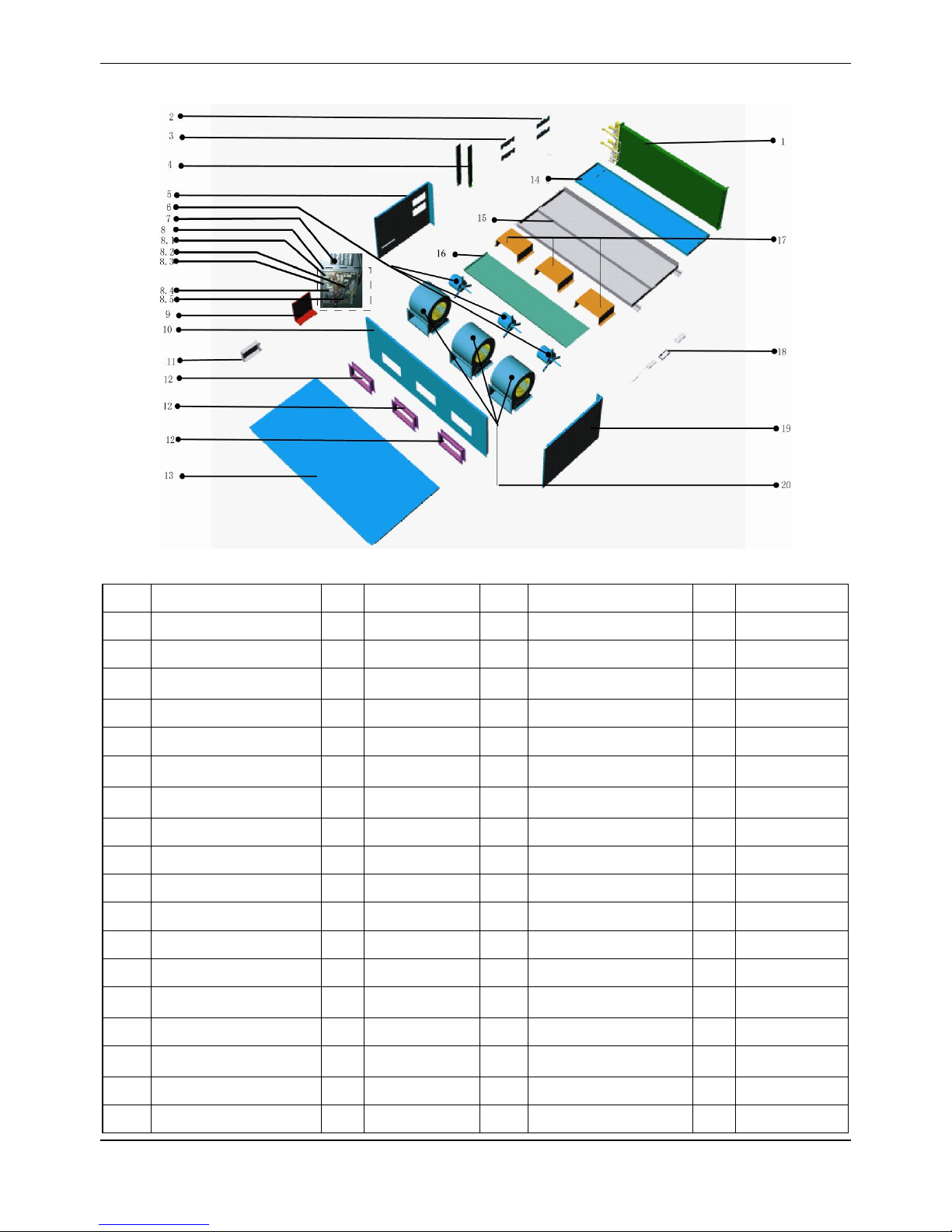
MCAC-UTSM-2012-12 R410A 50Hz Tropical Split AC
45
11.7 MTA-150CRN1
No.
Part Name
QTY
BOM Code
No.
Part Name
QTY
BOM Code
1
evaportator ass'y
1
201570990081
8.5
Wire joint, 7p
1
202301450056
1.1
Evaporator
1
201586900502
8.6
Wire joint
2
202301450122
1.2
Evaporator
1
201586900504
9
Components of electronic
control box cover
1
201270600180
1.3
Evaporator
1
201586900505
10
Front panel ass'y
1
201286910001
1.4
Evaporator
1
201586900506
11
Capacitor box
1
201286900512
1.5
evaportaor input pipe
ass'y(II)
1
201670990106
12
Air outlet ass'y
3
201285000612
1.6
evaporator input pipe
ass'y(I)
1
201670990104
13
Top cover ass'y
1
201286900504
1.7
Output pipe ass'y
2
201686900500
14
Drainage pan ass'y
1
201252600013
2
Pipe clamp board ass'y
2
201286900505
15
Base ass'y
1
201286910002
3
Clamp board ass'y
2
201286900524
16
Drainage pan ass'y
1
201252600023
4
Evaporator left clapboard
2
201252600012
17
Motor installation board
3
201286910000
5
Left clapboard ass'y
1
201286900502
18
Remote controller
1
203355090107
6
Motor
3
202400400071
19
Right cover ass'y
1
201286900503
8
Indoor electronic control
box components
1
203370990033
20
Volute shell ass'y
3
201200300201
8.1
E-part box
1
201285000350
21
Room temp sensor ass'y
1
202301300214
8.2
Main control board
assembly
1
201370900071
22
Temp.sensor ass'y
1
202440500002
8.3
Relay
3
202300800003
23
Display board ass'y
1
203342090023
8.4
Transformer
1
202300900093
Page 46

R410A 50Hz Tropical Split AC MCAC-UTSM-2012-12
46
11.8 MHB-76CRN1
No.
Part Name
QTY
BOM Code
No.
Part Name
QTY
BOM Code
1
Evaporator Sealed board
1
201286900317
13.4
Transformer
1
202300900093
2
Side board ass'y
1
201286900316
13.5
Wire joint, 7p
1
202301450056
3
Drainage pan ass'y
1
201285000677
13.6
Wire joint
2
202301450122
4
Motor
2
202400400071
14
The left side plate
assembly
1
201270990012
5
Motor supporter ass'y
2
201285000683
15
Seal plate evaporator
components left
1
201270990009
6
Front panel ass'y
1
201285000668
16
Temp.sensor ass'y
1
202301300133
7
Air outlet ass'y
2
201285000612
17
Base ass'y
1
201285000667
8
Remote controller
1
203355090107
18
evaporator ass'y
1
201570990079
9
Display board ass'y
1
203342090051
18.1
evaporator inputing pipe
ass'y
1
201670990091
10
Compressor capacitor
2
202401010101
18.1.1
One way valve
1
201600800166
11
Compressor capacitor box
2
201226190015
18.2
evaporator
1
201570990080
12
Components of electronic
control box cover
1
201270600180
18.3
evaporator input pipe
ass'y
1
201670990087
13
Indoor electronic control
box components
1
203370990033
19
Room temp sensor ass'y
1
202301300214
13.1
E-part box
1
201285000350
20
Rear board ass'y
1
201286900313
13.2
Main control board
assembly
1
201370900071
21
Top cover ass'y
1
201286900314
13.3
Relay
3
202300800003
22
Volute shell ass'y
2
201200300201
Page 47

MCAC-UTSM-2012-12 R410A 50Hz Tropical Split AC
47
11.9 MHB-76HRN1
No.
Part Name
QTY
BOM Code
No.
Part Name
QTY
BOM Code
1
Evaporator Sealed board
1
201286900317
13.4
Transformer
1
202300900093
2
Side board ass'y
1
201286900316
13.5
Wire joint, 7p
1
202301450056
3
Drainage pan ass'y
1
201285000677
13.6
Wire joint
2
202301450122
4
Motor
2
202400400071
14
The left side plate
assembly
1
201270990012
5
Motor supporter ass'y
2
201285000683
15
Seal plate evaporator
components left
1
201270990009
6
Front panel ass'y
1
201285000668
16
Temp.sensor ass'y
1
202301300133
7
Air outlet ass'y
2
201285000612
17
Base ass'y
1
201285000667
8
Remote controller
1
203355090100
18
evaporator ass'y
1
201570990079
9
Display board ass'y
1
203342090051
18.1
evaporator inputing pipe
ass'y
1
201670990091
10
Compressor capacitor
2
202401010101
18.1.1
One way valve
1
201600800166
11
Compressor capacitor box
2
201226190015
18.2
evaporator
1
201570990080
12
Components of electronic
control box cover
1
201270600180
18.3
evaporator input pipe ass'y
1
201670990087
13
Indoor electronic control
box components
1
203370990033
19
Room temp sensor ass'y
1
202301300214
13.1
E-part box
1
201285000350
20
Rear board ass'y
1
201286900313
13.2
Main control board
assembly
1
201370900071
21
Top cover ass'y
1
201286900314
13.3
Relay
3
202300800003
22
Volute shell ass'y
2
201200300201
Page 48

R410A 50Hz Tropical Split AC MCAC-UTSM-2012-12
48
11.10 MHB-96CRN1
No.
Part Name
QTY
BOM Code
No.
Part Name
QTY
BOM Code
1
Evaporator Sealed board
1
201286900317
13.4
Transformer
1
202300900093
2
Side board ass'y
1
201286900316
13.5
Wire joint, 7p
1
202301450056
3
Drainage pan ass'y
1
201285000677
13.6
Wire joint
2
202301450122
4
Fan motor
2
202400410853
14
The left side plate
assembly
1
201270990012
5
Motor supporter ass'y
2
201285000683
15
Seal plate evaporator
components left
1
201270990009
6
Front panel ass'y
1
201285000668
16
Temp.sensor ass'y
1
202301300133
7
Air outlet ass'y
2
201285000612
17
Base ass'y
1
201285000667
8
Remote controller
1
203355090107
18
Evaporator parts
1
201570990077
9
Display board ass'y
1
203342090051
18.1
Enter the evaporator
tube assembly
1
201670990082
10
Compressor capacitor
2
202401010101
18.1.1
One way valve
1
201600800166
11
Compressor capacitor box
2
201226190015
18.2
Evaporator
1
201570990078
12
Components of electronic
control box cover
1
201270600180
18.3
Evaporator tube
assembly output
1
201670990080
13
Indoor electronic control
box components
1
203370990033
19
Room temp sensor ass'y
1
202301300214
13.1
E-part box
1
201285000350
20
Rear board ass'y
1
201286900313
13.2
Main control board
assembly
1
201370900071
21
Top cover ass'y
1
201286900314
13.3
Relay
3
202300800003
22
Volute shell ass'y
2
201200300201
Page 49

MCAC-UTSM-2012-12 R410A 50Hz Tropical Split AC
49
11.11 MHB-96HRN1
No.
Part Name
QTY
BOM Code
No.
Part Name
QTY
BOM Code
1
Evaporator Sealed board
1
201286900317
13.4
Transformer
1
202300900093
2
Side board ass'y
1
201286900316
13.5
Wire joint, 7p
1
202301450056
3
Drainage pan ass'y
1
201285000677
13.6
Wire joint
2
202301450122
4
Fan motor
2
202400410853
14
The left side plate
assembly
1
201270990012
5
Motor supporter ass'y
2
201285000683
15
Seal plate evaporator
components left
1
201270990009
6
Front panel ass'y
1
201285000668
16
Temp.sensor ass'y
1
202301300133
7
Air outlet ass'y
2
201285000612
17
Base ass'y
1
201285000667
8
Remote controller
1
203355090100
18
Evaporator parts
1
201570990077
9
Display board ass'y
1
203342090051
18.1
Enter the evaporator
tube assembly
1
201670990082
10
Compressor capacitor
2
202401010101
18.1.1
One way valve
1
201600800166
11
Compressor capacitor box
2
201226190015
18.2
Evaporator
1
201570990078
12
Components of electronic
control box cover
1
201270600180
18.3
Evaporator tube
assembly output
1
201670990080
13
Indoor electronic control
box components
1
203370990033
19
Room temp sensor ass'y
1
202301300214
13.1
E-part box
1
201285000350
20
Rear board ass'y
1
201286900313
13.2
Main control board
assembly
1
201370900071
21
Top cover ass'y
1
201286900314
13.3
Relay
3
202300800003
22
Volute shell ass'y
2
201200300201
Page 50

R410A 50Hz Tropical Split AC MCAC-UTSM-2012-12
50
12. Troubleshooting
PRE-DEF lamp(cooling and heating type)
or fan only lamp(cooling only type)
Infrared signal receiver
Operation lamp
Timer lamp
Alarm lamp
Manual Switch
Type
OPT.
Light
TME.
Light
DEF.
Light
ALARM
Light
Remarks
Room temp. sensor error
- ☆ - - Manual reset
Evaporator temp. sensor error
☆ - - - Manual reset
Condenser temp. sensor error
- - ☆ - Manual reset
Water pump temp. sensor error
☆ - - ☆ Manual reset
The PRO terminal on PCB of
indoor unit without connected to
grounding wire
☆ ☆ ☆ ☆ Manual reset
EEPROM error
☆ ☆ - - Manual reset
Condensing water level full error
- - - ☆ Manual reset
Note:
OPT. Light: operation light; TME. Light: timer light;
DEF. Light: defrosting light; ☆: the light flashing.
Page 51

MCAC-UTSM-2012-12 R410A 50Hz Tropical Split AC
51
13.1 Malfunctions of air conditioner
If any of the following malfunctions occur, stop operation of the air conditioner immediately. Turn off the power
switch, and contact the local after sales service center of manufacturer:
The RUN lamp flashes quickly (2 flash per second).
After turning off the power switch and then turning it on again, the RUN lamp still flashes quickly.
The receiving function of the remote controller fails, or the start/ shutdown operation is abnormal.
The fuse blows out frequently, or the circuit breaker protection occurs frequently.
Obstacles or water enter the air conditioner.
Condensing water leaks from indoor unit.
Other malfunctions occur.
Page 52

R410A 50Hz Tropical Split AC MCAC-UTSM-2012-12
52
If the air conditioner fails and does not meet the above phenomena, check the system as the following table:
Symptoms
Causes
Handling methods
The unit does not
work
Power supply fails.
Operate after power resumes.
Power switch is not connected.
Connect the power supply properly.
Fuse blows out or circuit breaker snaps off.
Replace the fuse or check whether
electric leakage occurs.
The remote controller or the wire controller
fails.
Check the remote controller or wire
controller.
Air flowing
normally but
completely can’t
cooling
Temperature setting is improper.
Temperature setting is higher than the
room temperature in cooling mode. Or
temperature setting is lower than the
room temperature in heating mode.
3-minute protection of compressor.
Waiting for 3 minutes.
The unit starts or
stops frequently
The system is lack of refrigerant. Or there is
too much refrigerant in the system.
Fix the leakage places, and charge the
proper quantity of refrigerant.
Air or non-condensable gas exists in the
refrigerant system.
Vacuum the system and charge
refrigerant again.
Compressor fails.
Repair or replace the compressor.
The voltage is too high or too low.
Install a voltage regulator.
The refrigerant pipe is obstructed.
Locate and replace that part.
Poor cooling effect
The heat exchanger of outdoor unit or indoor
unit is too dirty.
Clean the heat exchanger.
The filter is too dirty.
Clean the filter.
Air inlet or air outlet of the indoor/ outdoor
unit is blocked.
Remove obstacles to keep well
ventilating.
Doors or windows of the room are open.
Close all the windows and doors.
Directly exposed to sunlight.
Use curtain to obstruct sunlight.
Too many heat sources in the room.
Reduce the heat sources.
The outdoor ambient temperature is too
high.
The cooling effect is poor but normal.
The system is lack of refrigerant.
Fix the leakage places, and charge the
proper quantity of refrigerant.
Poor heating
effect
The outdoor ambient temperature is lower
than -7℃.
Use an assistance heating device.
Doors or windows of the room are not closed
tightly.
Close the doors and windows properly.
The system is lack of refrigerant.
Fix the leakage places, and charge the
proper quantity of refrigerant.
Page 53

MCAC-UTSM-2012-12 R410A 50Hz Tropical Split AC
53
Symptoms
Causes
Handling methods
The fan speed
cannot be
changed
Check whether the mode marked on the
screen is “AUTO”.
When the “AUTO” mode is selected, the
unit will change the fan speed
automatically.
Check whether the mode marked on the
screen is “DEWET”.
When the “DEWET” mode is selected,
the unit will change the fan speed
automatically. The fan speed can be
selected in “COOLING”,”HEATING”
and ”SUPPLY AIR” mode.
The “ON/OFF”
button of remote
controller do not
work
Check whether the batteries of remote
controller are exhausted.
Replace the batteries.
The “ON/OFF”
lamp extinguishes
Check whether the time set on the timer has
expired.
Restart the unit.
The “TIMER ON”
lamp extinguishes
Check whether the time set on the timer has
expired.
It comes to the setting time and the unit
stat running automatically.
No receiving
sounds from the
indoor unit even
when the
“ON/OFF” button
is pressed
Check whether the signal transmitter of the
remote controller is properly directed to the
infrared signal receiver of the indoor unit
when the “ON/OFF” button is pressed.
Directly transmit the signal transmitter of
the remote controller to the infrared
signal receiver of the indoor unit, and
then push the “ON/OFF” button twice.
The buttons of the
remote controller
do not work
Check whether the settings are locked.
Push the “LOCK” button again.
Page 54

R410A 50Hz Tropical Split AC MCAC-UTSM-2012-12
54
Operation lamp flashes:
No
Yes
No
Yes
All lamps flashing at 5Hz
Judge 1: The PRO terminal on PCB of indoor unit without connecting to grounding wire
Validate: Check whether the PRO terminal on PCB of indoor
unit without connected to grounding wire.
Connect it to grounding wire.
Judge 2: Optical coupler on PCB malfunction
Validate: Check whether the Optical coupler is normal.
Replace optical coupler
Replace indoor PCB.
Page 55

MCAC-UTSM-2012-12 R410A 50Hz Tropical Split AC
55
Operation lamp flashes:
Timer lamp flashing at 5Hz
Room temperature sensor malfunction
Judge 1: Check the room temperature sensor
Is break off.
Connects it well.
Judge 2: Check the room temperature sensor
is abnormal.
Validate: Check whether the resistance of the
temperature sensor is correct according to Annex 1.
Replace temperature sensor
Replace indoor PCB.
Yes
No
Yes
No
Page 56

R410A 50Hz Tropical Split AC MCAC-UTSM-2012-12
56
Operation lamp flashes:
Yes
No
No
Yes
Replace temperature sensor
Operation lamp flashing at 5Hz
Evaporate temperature sensor is abnormal.
Judge 1: Check evaporate temperature sensor is break off.
Judge 2: Evaporate temperature sensor is abnormal.
Validate: Check whether the resistance of the room
temperature sensor is correct according to Annex 1.
Replace temperature sensor
Replace indoor PCB.
Page 57

MCAC-UTSM-2012-12 R410A 50Hz Tropical Split AC
57
Operation lamp flashes:
Defrosting lamp flashing at 5Hz
Condenser temperature sensor malfunction
Judge 1: Check condenser temperature sensor is break off.
Replace temperature sensor
Yes
Judge 2: Condenser temperature sensor is abnormal.
No
Validate: Check whether the resistance of the condenser
temperature sensor is correct according to Annex 1.
Replace temperature sensor
No
Yes
Replace indoor PCB.
Page 58

R410A 50Hz Tropical Split AC MCAC-UTSM-2012-12
58
13. Accessories
Name
Qty.
Shape
Usage
Owner’s manual
1
---
Installation manual
1
---
Remote controller manual
1
---
Water pipe 1 ---
Connect to water drainage pipe
Display board subassembly
1
---
Connect to control signal
Protective sleeve for refrigerant inlet and
outlet pipes
2
---
Remote controller
1
---
Remote controller mounting bracket
1 Placed the remote controller
AAA battery
2
---
Page 59

MCAC-UTSM-2012-12 R410A 50Hz Tropical Split AC
59
Floor-standing Type
1. Features ......................................................................................... 60
2. Specifications ................................................................................ 61
3. Dimensions .................................................................................... 62
4. Service Space ................................................................................ 63
5. Refrigerant cycle diagram ........................................................... 64
6. Wiring Diagrams ............................................................................ 65
7. Capacity Tables ............................................................................. 67
8. Electric Characteristics ................................................................. 75
9. Sound Levels ................................................................................. 76
10. Exploded View ............................................................................. 77
11. Troubleshooting .......................................................................... 85
12. Accessories ................................................................................. 90
Page 60

R410A 50Hz Tropical Split AC MCAC-UTSM-2012-12
60
1. Features
1. The appearance is novel, luxurious, refined.
2. High capacity of cooling/heating, efficient, and energy-saving.
3. Adopt advanced and high efficient scroll compressor, wide angle and long distance air supply.
4. Remote control standard, screen control optional.
5. Easy installation and maintenance.
6. Suit for hotel, meeting room, airport lounge, etc. public occasion use.
Page 61

MCAC-UTSM-2012-12 R410A 50Hz Tropical Split AC
61
2. Specifications
Model
MFA-76CRN1
MFA-76HRN1
MFA-96CRN1
MFA-96HRN1
Power supply
-
220~240V-1Ph-50Hz
220~240V-1Ph-50Hz
Temp. setting range
℃
≥17
≤30
≥17
≤30
Rated input power
W
11700
11700
14400
14400
Rated current
A
19.3
19.3
23.7
23.7
Cooling
Capacity
Btu/h
75100
75100
95500
95500
W
22000
22000
28000
28000
Input power
W
7500
7500
9600
9600
EER
W/W
2.93
2.93
2.92
2.92
Heating
Capacity
Btu/h / 85300
/
105800 W /
25000
/
31000
Input power W /
8300
/
10300
COP
W/W / 3.01 / 3.01
Indoor air flow (Hi/Med/Lo)
m3/h
4250/3835/3485
4250/3835/3485
5100/4520/3980
5100/4520/3980
Indoor noise level(Hi)
dB(A)
53
53
54
54
Refrigerant
Type
-
R410A
R410A
Control
-
Capillary
Capillary
Fan
Type - Centrifugal fan
Centrifugal fan
Centrifugal fan
Centrifugal fan
Dimension
mm
Φ250
Φ250
Φ250
Φ250
Drive type - Direct
Direct
Direct
Direct
Motor input * No.
W
590
590
590
590
Motor speed
rpm
870
870
870
870
Coil
Type - Copper tube and aluminum fin
Copper tube and aluminum fin
Tube size
mm
Φ 9.52
Φ 9.52
Φ 9.52
Φ 9.52
No. of rows - 2 2 3
3
Fin per inch
FPI
16
16
16
16
Length* height
mm
982*715.5
982*715.5
983*715.5
983*715.5
Controller - Remote controller
Remote controller
Drain pipe size
mm
41
41
41
41
Dimension (W*H*D)
mm
1200*1860*420
1200*1860*420
1200*1860*420
1200*1860*420
Packing (W*H*D)
mm
1362*2023*582
1362*2023*582
1362*2023*582
1362*2023*582
Net/Gross weight
kg
158/174
158/174
158/174
158/174
Shipping Qty per 20'/40'/40'HD
pcs
15/32/32
15/32/32
15/32/32
15/32/32
Notes:
1. Nominal cooling capacities are based on the following conditions:
Indoor temp: 27°CDB, 19°CWB; Outdoor temp: 35°CDB; Equivalent ref. piping: 7.5m (horizontal)
2. Nominal heating capacities are based on the following conditions:
Indoor temp: 20°CDB; Outdoor temp: 7°CDB, 6°CWB; Equivalent ref. piping: 7.5m (horizontal)
Page 62

R410A 50Hz Tropical Split AC MCAC-UTSM-2012-12
62
3. Dimensions
Page 63
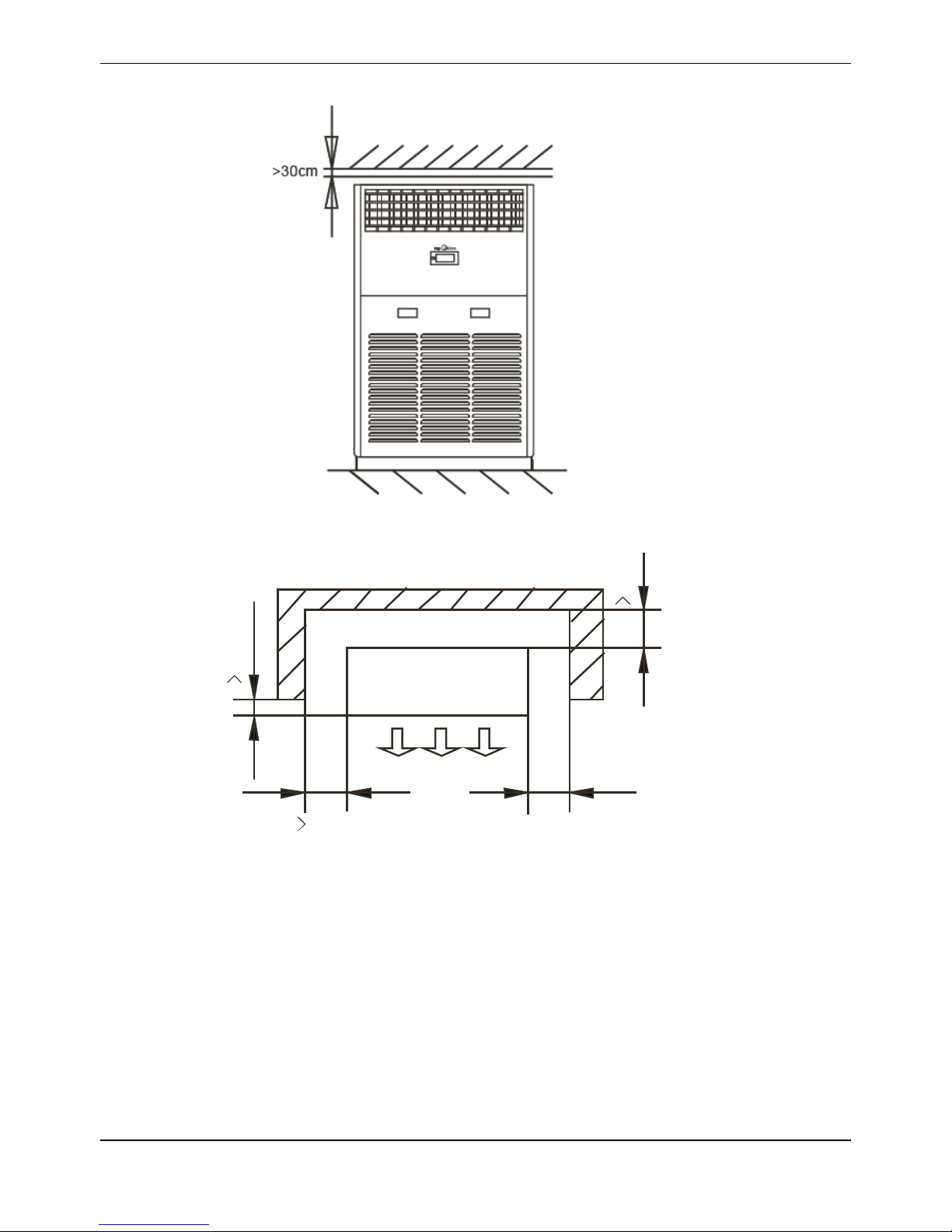
MCAC-UTSM-2012-12 R410A 50Hz Tropical Split AC
63
4. Service Space
Front view
1
0
c
m
1
0
c
m
Rear
30 cm
No obstacle in front of it
Top view
Page 64

R410A 50Hz Tropical Split AC MCAC-UTSM-2012-12
64
5. Refrigerant cycle diagram
5.1 Cooling only: MFA-76CR, MFA-96CR
Discharge temp. sensor
HP Switch
Compressor
Liquid-gas seperator
Outdoor heat-exchanger
Stop valve
Stop valve
Indoor unit
LP Switch
T4
T2
T3
Cooling
Indoor
heat-exchanger
5.2 Cooling and heating: MFA-76HR, MFA-96HR
Discharge temp. sensor
HP Switch
Compressor
4-way valve
Liquid-gas seperator
Outdoor heat-exchanger
Stop valve
Stop valve
Indoor unit
Check valve
LP Switch
T4
T2
T3
Heating
Cooling
Indoor
heat-exchanger
Page 65

MCAC-UTSM-2012-12 R410A 50Hz Tropical Split AC
65
6. Wiring Diagrams
6.1 MFA-76CR, MFA-96CR
Item
Name
Item
Name
Item
Name
CAP1
Fan capacitance
RT1
Room temp. sensor
XS1-3
Connector plugs
FAN
Indoor fan
RT2
Pipe temp. sensor
SYN
Swing motor
XT1-3
Connector
JDQ
Fan aided control board
-
-
T4
Transformer
XP1-3
Connector plugs
-
-
Page 66
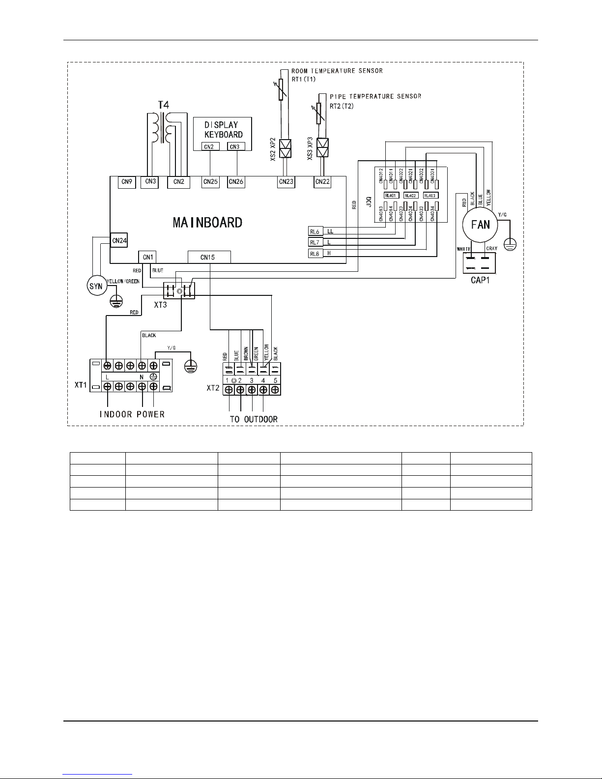
R410A 50Hz Tropical Split AC MCAC-UTSM-2012-12
66
6.2 MFA-76HR, MFA-96HR
Item
Name
Item
Name
Item
Name
CAP1
Fan capacitance
RT1
Room temp. sensor
XS1-3
Connector plugs
FAN
Indoor fan
RT2
Pipe temp. sensor
SYN
Swing motor
XT1-3
Connector
JDQ
Fan aided control board
-
-
T4
Transformer
XP1-3
Connector plugs
-
-
Page 67
MCAC-UTSM-2012-12 R410A 50Hz Tropical Split AC
67
7. Capacity Tables
7.1 Cooling:
7.1.1 MFA-76CRN1
Gross Cooling Capacity (kW)
Outdoor DB(°C)
29.40
35.00
Indoor
WB(°C)
16.10
19.40
22.80
16.10
19.40
22.80
CFM
DB(°C)
TGC
SHC
PI
TGC
SHC
PI
TGC
SHC
PI
TGC
SHC
PI
TGC
SHC
PI
TGC
SHC
PI
1950
23.9
20.1
16.5
6.48
22.1
12.5
6.68
23.5
5.4
6.81
19.3
15.8
6.91
21.0
11.8
7.14
22.2
5.1
7.28
26.7
20.8
18.9
6.50
22.6
14.6
6.70
24.0
10.3
6.83
19.7
17.9
6.93
21.4
13.8
7.16
22.7
9.8
7.30
29.4
21.5
20.7
6.52
23.0
18.9
6.72
24.5
14.6
6.85
20.1
19.3
6.95
21.8
17.9
7.18
23.1
13.8
7.32
32.2
22.3
21.8
6.53
23.5
21.4
6.73
24.9
18.3
6.86
20.5
20.1
6.96
22.2
20.2
7.20
23.6
17.4
7.34
2130
23.9
20.7
17.4
6.68
22.7
13.1
6.88
24.1
5.7
7.01
19.9
16.7
7.11
21.6
12.5
7.34
22.8
5.4
7.48
26.7
21.4
19.8
6.70
23.2
16.5
6.90
24.6
10.8
7.03
20.3
18.8
7.13
22.0
15.6
7.36
23.3
10.2
7.50
29.4
22.1
21.7
6.72
23.7
19.9
6.92
25.1
15.3
7.05
20.7
20.3
7.15
22.4
18.9
7.38
23.8
14.5
7.52
32.2
22.9
22.9
6.73
24.1
22.3
6.93
25.6
19.1
7.07
21.1
21.1
7.17
22.9
21.2
7.40
24.2
18.1
7.54
2500
23.9
21.2
19.4
6.92
23.2
14.5
7.25
24.6
6.4
7.25
20.4
18.7
7.35
22.1
13.8
7.47
23.3
6.0
7.72
26.7
21.9
21.9
6.94
23.7
18.2
7.14
25.1
12.0
7.27
20.8
20.8
7.37
22.0
17.3
7.50
23.8
11.4
7.74
29.4
22.7
22.7
6.96
24.2
22.2
7.16
25.6
17.0
7.29
21.2
21.2
7.39
23.0
21.1
7.62
24.3
16.1
7.76
32.2
23.5
23.5
6.97
24.7
22.4
7.18
26.1
21.2
7.31
21.6
21.6
7.41
23.4
21.3
7.64
24.8
20.1
7.78
Page 68

R410A 50Hz Tropical Split AC MCAC-UTSM-2012-12
68
Gross Cooling Capacity (kW)
Outdoor DB(°C)
40.60
46.10
51.70
Indoor
WB(°C)
16.10
19.40
22.80
16.10
19.40
22.80
16.10
19.40
22.80
CFM
DB(°C)
TGC
SHC
PI
TGC
SHC
PI
TGC
SHC
PI
TGC
SHC
PI
TGC
SHC
PI
TGC
SHC
PI
TGC
SHC
PI
TGC
SHC
PI
TGC
SHC
PI
1950
23.9
17.5
14.4
8.07
19.1
10.8
8.31
20.4
4.7
8.46
16.0
13.1
8.26
17.5
9.9
8.52
18.7
4.3
8.77
15.1
12.4
8.83
16.4
9.3
9.19
17.5
4.0
9.44
26.7
17.9
16.2
8.09
19.5
12.6
8.33
20.8
8.9
8.48
16.4
14.9
8.28
17.9
11.6
8.54
19.1
8.2
8.79
15.4
14.0
8.85
16.7
10.8
9.21
17.8
7.7
9.46
29.4
18.2
17.5
8.11
19.8
16.3
8.35
21.2
12.6
8.50
16.7
16.0
8.30
18.2
14.9
8.56
19.4
11.6
8.81
15.7
15.1
8.87
17.1
14.0
9.23
18.2
10.8
9.48
32.2
18.6
18.2
8.13
20.2
18.4
8.37
21.6
15.9
8.52
17.0
16.7
8.32
18.6
16.9
8.58
19.8
14.6
8.83
16.1
15.7
8.89
17.4
15.8
9.26
18.6
13.6
9.51
2130
23.9
18.1
15.2
8.27
19.7
11.4
8.51
21.0
4.9
8.66
16.6
14.0
8.46
18.1
10.5
8.72
19.3
4.6
8.97
15.7
13.2
9.03
17.0
9.8
9.39
18.1
4.3
9.64
26.7
18.5
17.1
8.29
20.1
14.2
8.53
21.4
9.4
8.68
17.0
15.7
8.48
18.5
13.1
8.74
19.7
8.6
8.99
16.1
14.9
9.05
17.4
12.3
9.41
18.5
8.1
9.66
29.4
18.8
18.5
8.31
20.5
17.2
8.55
21.8
13.3
8.70
17.3
17.0
8.50
18.8
15.8
8.76
20.1
12.2
9.01
16.4
16.1
9.07
17.7
14.9
9.43
18.8
11.5
9.68
32.2
19.2
19.2
8.33
20.9
19.3
8.57
22.2
16.6
8.72
17.7
17.7
8.52
19.2
17.8
8.78
20.5
15.3
9.04
16.7
16.7
9.10
18.1
16.7
9.46
19.2
14.3
9.71
2500
23.9
18.6
17.1
7.97
20.2
12.6
8.36
21.5
5.6
8.36
17.1
15.7
8.70
18.6
11.6
8.96
19.8
5.1
9.21
16.2
14.9
9.27
17.5
10.9
9.63
18.6
4.8
9.88
26.7
19.0
19.0
7.99
20.6
15.8
8.23
21.9
10.5
8.38
17.5
17.5
8.72
19.0
14.6
8.98
20.2
9.7
9.23
16.6
16.6
9.29
17.9
13.7
9.65
19.0
9.1
9.90
29.4
19.4
19.4
8.01
21.0
19.3
8.25
22.3
14.8
8.40
17.8
17.8
8.74
19.4
17.8
9.00
20.6
13.6
9.25
16.9
16.9
9.31
18.2
16.7
9.67
19.3
12.8
9.92
32.2
19.7
19.7
8.03
21.4
19.5
8.27
22.8
18.5
8.42
18.2
18.2
8.76
19.7
18.0
9.02
21.0
17.1
9.28
17.2
17.2
9.34
18.6
16.9
9.70
19.7
16.0
9.95
Notes:
1. DB = Dry Bulb Temperature (°C), WB = Wet Bulb Temperature (°C)
2. TGC = Total Cooling Capacity (kW)
3. SHC = Sensible Heating Capacity (kW)
4. PI = Power Input (kW)
Page 69

MCAC-UTSM-2012-12 R410A 50Hz Tropical Split AC
69
7.1.2 MFA-76HRN1
Gross Cooling Capacity (kW)
Outdoor DB(°C)
29.40
35.00
Indoor
WB(°C)
16.10
19.40
22.80
16.10
19.40
22.80
CFM
DB(°C)
TGC
SHC
PI
TGC
SHC
PI
TGC
SHC
PI
TGC
SHC
PI
TGC
SHC
PI
TGC
SHC
PI
1920
23.9
19.6
16.1
6.38
21.6
12.2
6.58
23.0
5.3
6.71
18.8
15.4
6.81
20.5
11.6
7.04
21.7
5.0
7.18
26.7
20.3
18.4
6.40
22.1
14.3
6.60
23.5
10.1
6.73
19.2
17.4
6.83
20.9
13.5
7.06
22.2
9.6
7.20
29.4
21.0
20.2
6.42
22.5
18.5
6.62
23.9
14.3
6.75
19.6
18.8
6.85
21.3
17.5
7.08
22.6
13.5
7.22
32.2
21.7
21.3
6.43
23.0
20.9
6.63
24.4
18.0
6.76
20.0
19.6
6.86
21.7
19.7
7.10
23.1
17.0
7.24
2100
23.9
20.2
17.0
6.58
22.3
12.9
6.78
23.6
5.6
6.91
19.4
16.3
7.01
21.1
12.2
7.24
22.4
5.3
7.38
26.7
20.9
19.4
6.60
22.7
16.1
6.80
24.1
10.6
6.93
19.8
18.3
7.03
21.5
15.2
7.26
22.8
10.0
7.40
29.4
21.6
21.2
6.62
23.2
19.5
6.82
24.6
15.0
6.95
20.2
19.8
7.05
21.9
18.4
7.28
23.3
14.2
7.42
32.2
22.4
22.4
6.63
23.6
21.9
6.83
25.1
18.7
6.96
20.6
20.6
7.07
22.4
20.7
7.30
23.7
17.7
7.44
2500
23.9
20.7
19.0
6.82
22.7
14.2
7.15
24.1
6.2
7.15
19.9
18.3
7.25
21.6
13.5
7.48
22.8
5.9
7.62
26.7
21.4
21.4
6.84
23.2
17.8
7.04
24.6
11.8
7.17
20.3
20.3
7.27
22.0
16.9
7.50
23.3
11.1
7.64
29.4
22.1
22.1
6.86
23.7
21.7
7.06
25.1
16.6
7.19
20.7
20.7
7.29
22.4
20.6
7.52
23.8
15.7
7.66
32.2
22.9
22.9
6.87
24.1
21.9
7.08
25.6
20.8
7.21
21.1
21.1
7.31
22.9
20.8
7.54
24.2
19.7
7.68
Page 70

R410A 50Hz Tropical Split AC MCAC-UTSM-2012-12
70
Gross Cooling Capacity (kW)
Outdoor DB(°C)
40.60
46.10
51.70
Indoor
WB(°C)
16.10
19.40
22.80
16.10
19.40
22.80
16.10
19.40
22.80
CFM
DB(°C)
TGC
SHC
PI
TGC
SHC
PI
TGC
SHC
PI
TGC
SHC
PI
TGC
SHC
PI
TGC
SHC
PI
TGC
SHC
PI
TGC
SHC
PI
TGC
SHC
PI
1920
23.9
17.1
14.0
8.16
18.7
10.5
8.40
19.9
4.6
8.55
15.6
12.8
8.35
17.1
9.7
8.61
18.3
4.2
8.86
14.8
12.1
9.16
16.0
9.1
9.52
17.1
4.0
9.77
26.7
17.4
15.8
8.18
19.0
12.3
8.42
20.3
8.8
8.57
15.9
14.5
8.37
17.4
11.3
8.63
18.6
8.0
8.88
15.1
13.7
9.18
16.4
10.6
9.54
17.5
7.5
9.79
29.4
17.8
17.1
8.20
19.4
15.9
8.44
20.7
12.3
8.59
16.2
15.6
8.39
17.8
14.6
8.65
19.0
11.3
8.90
15.4
14.8
9.20
16.7
13.7
9.56
17.8
10.6
9.81
32.2
18.1
17.8
8.22
19.8
18.0
8.46
21.2
15.6
8.61
16.6
16.2
8.41
18.1
16.5
8.67
19.4
14.3
8.92
15.7
15.4
9.23
17.0
15.5
9.59
18.2
13.4
9.84
2100
23.9
17.7
14.9
8.36
19.3
11.1
8.60
20.5
4.8
8.75
16.2
13.6
8.55
17.7
10.2
8.81
18.9
4.5
9.06
15.4
12.9
9.36
16.6
9.6
9.72
17.7
4.2
9.97
26.7
18.1
16.7
8.38
19.7
13.9
8.62
21.0
9.2
8.77
16.6
15.3
8.57
18.1
12.8
8.83
19.3
8.4
9.08
15.7
14.5
9.38
17.0
12.0
9.74
18.1
7.9
9.99
29.4
18.4
18.1
8.40
20.0
16.8
8.64
21.4
13.0
8.79
16.9
16.6
8.59
18.4
15.5
8.85
19.6
12.0
9.10
16.0
15.7
9.40
17.3
14.6
9.76
18.4
11.2
10.01
32.2
18.8
18.8
8.42
20.4
18.9
8.66
21.8
16.3
8.81
17.2
17.2
8.61
18.8
17.4
8.87
20.0
14.9
9.13
16.3
16.3
9.43
17.7
16.4
9.79
18.8
14.0
10.04
2500
23.9
18.2
16.7
8.06
19.8
12.3
8.45
21.0
5.4
8.45
16.7
15.3
8.79
18.2
11.4
9.05
19.4
5.0
9.30
15.9
14.6
9.60
17.1
10.7
9.96
18.2
4.7
10.20
26.7
18.6
18.6
8.08
20.2
15.5
8.32
21.5
10.3
8.47
17.1
17.1
8.81
18.6
14.3
9.07
19.8
9.4
9.32
16.2
16.2
9.62
17.5
13.4
9.98
18.6
8.9
10.23
29.4
18.9
18.9
8.10
20.6
18.9
8.34
21.9
14.5
8.49
17.4
17.4
8.83
18.9
17.4
9.09
20.1
13.3
9.34
16.5
16.5
9.64
17.8
16.4
10.00
19.0
12.6
10.26
32.2
19.3
19.3
8.12
21.0
19.1
8.36
22.3
18.1
8.51
17.7
17.7
8.85
19.3
17.5
9.12
20.5
16.7
9.37
16.8
16.8
9.67
18.2
16.5
10.03
19.3
15.7
10.28
Notes:
1. DB = Dry Bulb Temperature (°C), WB = Wet Bulb Temperature (°C)
2. TGC = Total Cooling Capacity (kW)
3. SHC = Sensible Heating Capacity (kW)
4. PI = Power Input (kW)
Page 71

MCAC-UTSM-2012-12 R410A 50Hz Tropical Split AC
71
7.1.3 MFA-96CRN1
Gross Cooling Capacity (kW)
Outdoor DB(°C)
29.40
35.00
Indoor
WB(°C)
16.10
19.40
22.80
16.10
19.40
22.80
CFM
DB(°C)
TGC
SHC
PI
TGC
SHC
PI
TGC
SHC
PI
TGC
SHC
PI
TGC
SHC
PI
TGC
SHC
PI
2360
23.9
25.9
21.2
8.71
28.0
15.8
8.91
29.4
6.8
9.04
25.2
20.6
9.14
26.8
15.2
9.37
28.1
6.5
9.51
26.7
26.8
24.3
8.73
28.6
18.5
8.93
30.0
12.9
9.06
25.7
23.3
9.16
27.4
17.7
9.39
28.7
12.4
9.53
29.4
27.7
26.7
8.75
29.2
23.9
8.95
30.6
18.2
9.08
26.2
25.2
9.18
27.9
22.9
9.41
29.3
17.4
9.55
32.2
28.7
28.1
8.77
29.7
27.0
8.97
31.2
22.9
9.11
26.7
26.2
9.21
28.5
25.9
9.44
29.8
21.9
9.58
600
23.9
26.5
22.2
8.91
28.6
16.5
9.11
30.0
7.1
9.24
25.8
21.7
9.34
27.5
15.9
9.48
28.7
6.8
9.71
26.7
27.4
25.4
8.93
29.2
20.7
9.13
30.6
13.4
9.26
26.3
24.4
9.36
28.0
19.9
9.51
29.3
12.9
9.73
29.4
28.4
27.8
8.95
29.8
25.0
9.15
31.2
19.0
9.28
26.8
26.3
9.38
28.6
24.0
9.53
29.9
18.2
9.75
32.2
29.4
29.4
8.97
30.4
28.1
9.18
31.8
23.8
9.31
27.4
27.4
9.41
29.1
27.0
9.55
30.5
22.7
9.78
3000
23.9
27.0
24.7
9.15
29.1
18.2
9.48
30.5
7.9
9.48
26.3
24.1
9.58
27.9
17.5
9.58
29.2
7.6
9.95
26.7
27.9
27.9
9.17
29.7
22.8
9.37
31.1
14.9
9.50
26.8
26.8
9.60
28.0
21.9
9.60
29.8
14.3
9.97
29.4
28.9
28.9
9.19
30.3
27.8
9.39
31.7
21.0
9.52
27.3
27.3
9.62
29.1
26.7
9.85
30.4
20.1
9.99
32.2
29.9
29.9
9.22
30.9
28.1
9.42
32.4
26.3
9.55
27.9
27.9
9.65
29.7
27.0
9.88
31.0
25.2
10.02
Page 72
R410A 50Hz Tropical Split AC MCAC-UTSM-2012-12
72
Gross Cooling Capacity (kW)
Outdoor DB(°C)
40.60
46.10
51.70
Indoor
WB(°C)
16.10
19.40
22.80
16.10
19.40
22.80
16.10
19.40
22.80
CFM
DB(°C)
TGC
SHC
PI
TGC
SHC
PI
TGC
SHC
PI
TGC
SHC
PI
TGC
SHC
PI
TGC
SHC
PI
TGC
SHC
PI
TGC
SHC
PI
TGC
SHC
PI
2360
23.9
22.3
18.3
10.40
23.9
13.5
10.64
25.1
5.8
10.79
20.8
17.1
10.59
22.3
12.6
10.85
23.5
5.4
11.10
20.5
16.8
11.62
21.8
12.3
11.98
22.9
5.3
12.23
26.7
22.7
20.7
10.43
24.3
15.8
10.67
25.6
11.0
10.82
21.2
19.3
10.62
22.7
14.7
10.88
23.9
10.3
11.13
20.9
19.0
11.65
22.2
14.4
12.01
23.3
10.1
12.26
29.4
23.2
22.3
10.46
24.8
20.3
10.70
26.1
15.6
10.85
21.7
20.8
10.65
23.2
19.0
10.91
24.4
14.5
11.16
21.3
20.5
11.68
22.7
18.6
12.04
23.8
14.2
12.29
32.2
23.6
23.2
10.48
25.3
23.0
10.72
26.7
19.6
10.87
22.1
21.7
10.67
23.6
21.5
10.93
24.9
18.3
11.19
21.8
21.3
11.71
23.1
21.0
12.07
24.3
17.8
12.32
2600
23.9
22.9
19.2
10.60
24.5
14.1
10.84
25.7
6.1
10.99
21.4
18.0
10.79
22.9
13.2
11.05
24.1
5.7
11.30
21.1
17.8
11.82
22.4
12.9
12.18
23.5
5.5
12.43
26.7
23.4
21.6
10.63
25.0
17.7
10.87
26.3
11.5
11.02
21.9
20.2
10.82
23.4
16.6
11.08
24.6
10.8
11.33
21.6
20.0
11.85
22.9
16.2
12.21
24.0
10.5
12.46
29.4
23.8
23.4
10.66
25.4
21.4
10.90
26.8
16.3
11.05
22.3
21.9
10.85
23.8
20.0
11.11
25.0
15.3
11.36
22.0
21.6
11.88
23.3
19.6
12.24
24.4
14.9
12.49
32.2
24.3
24.3
10.68
26.0
24.0
10.92
27.3
20.4
11.08
22.7
22.7
10.87
24.3
22.5
11.14
25.5
19.1
11.39
22.4
22.4
11.91
23.8
22.0
12.27
24.9
18.6
12.52
3000
23.9
23.4
21.5
10.84
25.0
15.6
11.23
26.2
6.8
11.23
21.9
20.1
11.03
23.4
14.6
11.29
24.6
6.4
11.54
21.6
19.8
12.06
22.9
14.3
12.42
24.0
6.2
12.67
26.7
23.9
23.9
10.87
25.5
19.6
11.11
26.8
12.8
11.26
22.4
22.4
11.06
23.9
18.3
11.32
25.1
12.0
11.57
22.1
22.1
12.09
23.4
18.0
12.45
24.5
11.7
12.70
29.4
24.3
24.3
10.90
26.0
23.8
11.14
27.3
18.1
11.29
22.8
22.8
11.09
24.3
22.3
11.35
25.6
16.9
11.60
22.5
22.5
12.12
23.8
21.9
12.48
24.9
16.5
12.73
32.2
24.8
24.8
10.92
26.5
24.1
11.17
27.8
22.6
11.32
23.3
23.3
11.12
24.8
22.6
11.38
26.1
21.2
11.63
22.9
22.9
12.15
24.3
22.1
12.51
25.4
20.7
12.76
Notes:
1. DB = Dry Bulb Temperature (°C), WB = Wet Bulb Temperature (°C)
2. TGC = Total Cooling Capacity (kW)
3. SHC = Sensible Heating Capacity (kW)
4. PI = Power Input (kW)
Page 73

MCAC-UTSM-2012-12 R410A 50Hz Tropical Split AC
73
7.1.4 MFA-96HRN1
Gross Cooling Capacity (kW)
Outdoor DB(°C)
29.40
35.00
Indoor
WB(°C)
16.10
19.40
22.80
16.10
19.40
22.80
CFM
DB(°C)
TGC
SHC
PI
TGC
SHC
PI
TGC
SHC
PI
TGC
SHC
PI
TGC
SHC
PI
TGC
SHC
PI
2360
23.9
25.4
20.8
8.48
27.5
15.6
8.68
28.9
6.7
8.81
24.7
20.2
8.91
26.4
14.9
9.14
27.6
6.4
9.28
26.7
26.3
23.9
8.50
28.1
18.2
8.70
29.5
12.7
8.83
25.2
22.9
8.93
26.9
17.4
9.16
28.2
12.1
9.30
29.4
27.2
26.2
8.52
28.6
23.5
8.72
30.1
17.9
8.85
25.7
24.7
8.95
27.4
22.5
9.18
28.7
17.1
9.32
32.2
28.2
27.6
8.54
29.2
26.6
8.74
30.7
22.6
8.87
26.2
25.7
8.97
28.0
25.4
9.21
29.3
21.6
9.35
2600
23.9
26.0
21.8
8.68
28.1
16.3
8.88
29.5
7.0
9.01
25.3
21.3
9.11
27.0
15.6
9.34
28.2
6.7
9.48
26.7
26.9
24.9
8.70
28.7
20.4
8.90
30.1
13.2
9.03
25.8
23.9
9.13
27.5
19.5
9.36
28.8
12.6
9.50
29.4
27.8
27.3
8.72
29.3
24.6
8.92
30.7
18.7
9.05
26.3
25.8
9.15
28.1
23.6
9.38
29.4
17.9
9.52
32.2
28.8
28.8
8.74
29.9
27.6
8.94
31.3
23.4
9.08
26.8
26.8
9.18
28.6
26.5
9.41
30.0
22.4
9.55
3000
23.9
26.5
24.3
8.92
28.6
17.9
9.25
30.0
7.8
9.25
25.8
23.7
9.35
27.5
17.2
9.58
28.7
7.4
9.72
26.7
27.4
27.4
8.94
29.2
22.5
9.14
30.6
14.6
9.27
26.3
26.3
9.37
28.0
21.5
9.60
29.3
14.0
9.74
29.4
28.4
28.4
8.96
29.8
27.3
9.16
31.2
20.7
9.29
26.8
26.8
9.39
28.6
26.2
9.62
29.9
19.8
9.76
32.2
29.4
29.4
8.98
30.4
27.6
9.19
31.8
25.9
9.32
27.4
27.4
9.42
29.1
26.5
9.65
30.5
24.8
9.79
Page 74

R410A 50Hz Tropical Split AC MCAC-UTSM-2012-12
74
Gross Cooling Capacity (kW)
Outdoor DB(°C)
40.60
46.10
51.70
Indoor
WB(°C)
16.10
19.40
22.80
16.10
19.40
22.80
16.10
19.40
22.80
CFM
DB(°C)
TGC
SHC
PI
TGC
SHC
PI
TGC
SHC
PI
TGC
SHC
PI
TGC
SHC
PI
TGC
SHC
PI
TGC
SHC
PI
TGC
SHC
PI
TGC
SHC
PI
2360
23.9
21.7
17.8
10.56
23.3
13.1
10.80
24.5
5.7
10.95
20.2
16.6
10.75
21.7
12.3
11.01
22.9
5.3
11.26
20.2
16.6
11.83
21.5
12.2
12.19
22.6
5.2
12.44
26.7
22.1
20.1
10.59
23.7
15.4
10.83
25.0
10.8
10.98
20.6
18.7
10.78
22.1
14.3
11.04
23.3
10.1
11.29
20.6
18.8
11.86
21.9
14.2
12.22
23.0
9.9
12.47
29.4
22.6
21.7
10.62
24.2
19.8
10.86
25.5
15.2
11.01
21.0
20.2
10.81
22.6
18.5
11.07
23.8
14.2
11.32
21.1
20.2
11.89
22.4
18.3
12.25
23.5
14.0
12.50
32.2
23.0
22.6
10.64
24.7
22.4
10.88
26.0
19.1
11.03
21.5
21.0
10.83
23.0
20.9
11.10
24.3
17.8
11.35
21.5
21.1
11.92
22.8
20.8
12.28
24.0
17.6
12.53
2600
23.9
22.3
18.7
10.76
23.9
13.8
11.00
25.1
5.9
11.15
20.8
17.5
10.95
22.3
12.9
11.21
23.5
5.5
11.46
20.8
17.5
12.03
22.1
12.8
12.39
23.2
5.5
12.64
26.7
22.7
21.1
10.79
24.3
17.3
11.03
25.6
11.2
11.18
21.2
19.7
10.98
22.7
16.1
11.24
23.9
10.5
11.49
21.3
19.7
12.06
22.6
16.0
12.42
23.7
10.4
12.67
29.4
23.2
22.7
10.82
24.8
20.9
11.06
26.2
15.9
11.21
21.7
21.2
11.01
23.2
19.5
11.27
24.4
14.9
11.52
21.7
21.3
12.09
23.0
19.3
12.45
24.1
14.7
12.70
32.2
23.7
23.7
10.84
25.3
23.4
11.09
26.7
19.9
11.24
22.1
22.1
11.03
23.7
21.9
11.30
24.9
18.6
11.55
22.1
22.1
12.12
23.5
21.7
12.48
24.6
18.4
12.73
3000
23.9
22.8
20.9
11.00
24.4
15.2
11.39
25.6
6.6
11.39
21.3
19.6
11.19
22.8
14.2
11.45
24.0
6.2
11.70
21.3
19.6
12.27
22.6
14.1
12.63
23.7
6.1
12.88
26.7
23.2
23.2
11.03
24.8
19.1
11.27
26.1
12.5
11.42
21.7
21.7
11.22
23.2
17.9
11.48
24.4
11.7
11.73
21.8
21.8
12.30
23.1
17.7
12.66
24.2
11.6
12.91
29.4
23.7
23.7
11.06
25.3
23.2
11.30
26.7
17.7
11.45
22.2
22.2
11.25
23.7
21.7
11.51
24.9
16.5
11.76
22.2
22.2
12.33
23.5
21.6
12.69
24.6
16.3
12.94
32.2
24.2
24.2
11.09
25.8
23.5
11.33
27.2
22.1
11.48
22.6
22.6
11.28
24.2
22.0
11.54
25.4
20.7
11.79
22.6
22.6
12.36
24.0
21.8
12.72
25.1
20.4
12.97
Notes:
1. DB = Dry Bulb Temperature (°C), WB = Wet Bulb Temperature (°C)
2. TGC = Total Cooling Capacity (kW)
3. SHC = Sensible Heating Capacity (kW)
4. PI = Power Input (kW)
Page 75

MCAC-UTSM-2012-12 R410A 50Hz Tropical Split AC
75
8. Electric Characteristics
Model
Indoor Unit
Power Supply
IFM
Hz
Voltage
Min.
Max.
MCA
MFA
KW
FLA
MFA-76CRN1
50
220-240
198
254
3.5
15
0.59
2.773
MFA-76HRN1
50
220-240
198
254
3.5
15
0.59
2.773
MFA-96CRN1
50
220-240
198
254
3.5
15
0.59
2.773
MFA-96HRN1
50
220-240
198
254
3.5
15
0.59
2.773
Note :
MCA: Min. Current Amps. (A)
MFA: Max. Fuse Amps. (A)
KW: Fan Motor Rated Output (KW)
FLA: Full Load Amps. (A)
IFM: Indoor Fan Motor
Model
Outdoor Unit
Power Supply
Compressor
OFM
Hz
Voltage
Min.
Max.
MCA
TOCA
MFA
MSC
RLA
KW
FLA
MOV-76CN1-C
50
380-415
342
438
17.5
18
20.5
86
16.5
0.573
2.613
MOV-76HN1-C
50
380-415
342
438
17.5
18
20.5
86
16.5
0.573
2.613
MOV-96CN1-C
50
380-415
342
438
20
21
23.8
110
20
1.373
6.26
MOV-96HN1-C
50
380-415
342
438
20
21
23.8
110
20
1.373
6.26
MOV-120CN1-C
50
380-400
342
440
25
28.6
30
147
21.4
1.373
6.26
MOV-120HN1-C
50
380-400
342
440
25
28.6
30
147
21.4
1.373
6.26
Note:
MCA: Min. Current Amps. (A) TOCA: Total Over-current Amps. (A)
MFA: Max. Fuse Amps. (A) MSC: Max. Starting Amps. (A)
RLA: Rated Locked Amps. (A) OFM: Outdoor Fan Motor
KW: Rated Motor Output (KW) FLA: Full Load Amps. (A)
Page 76

R410A 50Hz Tropical Split AC MCAC-UTSM-2012-12
76
9. Sound Levels
1m
Microphone
1m
Unit Number
Model
Noise level under three speeds of fan (dB(A))
1
MFA-76C(H)RN1
55
2
MFA-96(H)RN1
56
Page 77

MCAC-UTSM-2012-12 R410A 50Hz Tropical Split AC
77
10. Exploded View
10.1 MFA-76CRN1
Page 78

R410A 50Hz Tropical Split AC MCAC-UTSM-2012-12
78
No.
Part Name
QTY
BOM Code
No.
Part Name
QTY
BOM Code
1
Partition board ass'y
1
201286900018
28.7
Wire joint
1
202301450133
2
Fixing board ass'y
1
201286900017
29
E-part box cover
1
201243900000
3
Volute shell ass'y
1
201286900019
30
Base ass'y
1
201243900005
4
Motor up cover
1
201286000007
31
Waterproof boad ass'y
1
201286900031
5
Motor below cover
1
201286000052
32
Drainage pan ass'y
1
201286900046
6
Board
1
201285000321
33
Filter 1 201186900001
7
Supporting board ass'y
2
201286900005
34
Control tablet support
1
201286900041
8
Left panel ass'y
1
201286900023
35
Supporting board ass'y
1
201286900013
9
Fixing board ass'y
4
201286900027
36 1
201543990006
10
Back-left shore ass'y
1
201286900014
36.1
Evaporator input pipe
ass'y
1
201643990020
11
Supporting board ass'y
1
201286900049
36.2
throttle ass'y
1
201643900073
12
Sealed board ass'y
1
201286900047
36.2.1
One way valve
1
201600800166
13
Front-left shore ass'y
1
201286900012
36.3
Evaporator input pipe
ass'y
1
201643990024
14
Pole ass'y
2
201286900006
36.4
Component I output tube
evaporator
1
201643990022
15
Supporting board ass'y
2
201286900003
36.5
Component II output
tube evaporator
1
201643990026
16
Louver ass'y
5
201286900029
37
Side board ass'y
1
201286900024
17
Sleeve
10
202786900002
38
Sealed board ass'y
1
201286900048
18
Grille
12
201140500027
39
Filter bar
2
201286900050
19
Link 1 201186900002
40
Pipe preforming
1
201286900040
20
Air outlet frame ass'y
1
201286900028
41
Pipe preforming
1
201286900039
21
Crank
1
201186900003
42
Pillar ass'y
1
201286900015
22
Motor
1
202400100019
43
Cover ass'y
1
201243900003
23
Panel ass'y
1
201286900032
44
Cover ass'y
1
201243900002
24
Capacitor fixing board
1
201286900010
45
Top cover ass'y
1
201243900001
25
Compressor capacitor
1
202401000410
46
Volute shell ass'y
1
201286900020
26
Capacitor clamp
1
201200100010
47
Motor below cover
1
201286000053
27
Compressor capacitor box
1
201226190015
48
Motor up cover
1
201286000008
28
Indoor electric control box
components
1
203343990001
49
Motor bracket
1
201285000306
28.1
Electrical box
1
201286900044
50
Motor
1
202400480012
28.2
Indoor control board
assembly
1
201343900012
51
room temp sensor ass'y
1
202301300197
28.3
Auxiliary fan control board
assembly
1
201386900011
52
Temp.sensor ass'y
1
202301300437
28.4
Transformer
1
202300900093
53
Remote controller
1
203355090107
28.5
Wire joint,5p
1
202301450085
54
Display and control box
components
1
2033439A0008
28.6
Wire joint
1
202301450122
55
Installation bracket ass'y
1
201155000024
Page 79

MCAC-UTSM-2012-12 R410A 50Hz Tropical Split AC
79
10.2 MFA-76HRN1
Page 80

R410A 50Hz Tropical Split AC MCAC-UTSM-2012-12
80
No.
Part Name
QTY
BOM Code
No.
Part Name
QTY
BOM Code
1
Partition board ass'y
1
201286900018
28.7
Wire joint
1
202301450133
2
Fixing board ass'y
1
201286900017
29
E-part box cover
1
201243900000
3
Volute shell ass'y
1
201286900019
30
Base ass'y
1
201243900005
4
Motor up cover
1
201286000007
31
Waterproof boad ass'y
1
201286900031
5
Motor below cover
1
201286000052
32
Drainage pan ass'y
1
201286900046
6
Board
1
201285000321
33
Filter 1 201186900001
7
Supporting board ass'y
2
201286900005
34
Control tablet support
1
201286900041
8
Left panel ass'y
1
201286900023
35
Supporting board ass'y
1
201286900013
9
Fixing board ass'y
4
201286900027
36 1
201543990006
10
Back-left shore ass'y
1
201286900014
36.1
Evaporator input pipe
ass'y
1
201643990020
11
Supporting board ass'y
1
201286900049
36.2
throttle ass'y
1
201643900073
12
Sealed board ass'y
1
201286900047
36.2.1
One way valve
1
201600800166
13
Front-left shore ass'y
1
201286900012
36.3
Evaporator input pipe
ass'y
1
201643990024
14
Pole ass'y
2
201286900006
36.4
Component I output tube
evaporator
1
201643990022
15
Supporting board ass'y
2
201286900003
36.5
Component II output
tube evaporator
1
201643990026
16
Louver ass'y
5
201286900029
37
Side board ass'y
1
201286900024
17
Sleeve
10
202786900002
38
Sealed board ass'y
1
201286900048
18
Grille
12
201140500027
39
Filter bar
2
201286900050
19
Link 1 201186900002
40
Pipe preforming
1
201286900040
20
Air outlet frame ass'y
1
201286900028
41
Pipe preforming
1
201286900039
21
Crank
1
201186900003
42
Pillar ass'y
1
201286900015
22
Motor
1
202400100019
43
Cover ass'y
1
201243900003
23
Panel ass'y
1
201286900032
44
Cover ass'y
1
201243900002
24
Capacitor fixing board
1
201286900010
45
Top cover ass'y
1
201243900001
25
Compressor capacitor
1
202401000410
46
Volute shell ass'y
1
201286900020
26
Capacitor clamp
1
201200100010
47
Motor below cover
1
201286000053
27
Compressor capacitor box
1
201226190015
48
Motor up cover
1
201286000008
28
Indoor electric control box
components
1
203343900002
49
Motor bracket
1
201285000306
28.1
Electrical box
1
201286900044
50
Motor
1
202400480012
28.2
Indoor control board
assembly
1
201343900015
51
room temp sensor ass'y
1
202301300197
28.3
Auxiliary fan control board
assembly
1
201386900011
52
Temp.sensor ass'y
1
202301300437
28.4
Transformer
1
202300900093
53
Remote controller
1
203355090100
28.5
Wire joint,5p
1
202301450085
54
Display and control box
components
1
2033439A0008
28.6
Wire joint
1
202301450122
55
Installation bracket ass'y
1
201155000024
Page 81

MCAC-UTSM-2012-12 R410A 50Hz Tropical Split AC
81
10.3 MFA-96CRN1
Page 82

R410A 50Hz Tropical Split AC MCAC-UTSM-2012-12
82
No.
Part Name
QTY
BOM Code
No.
Part Name
QTY
BOM Code
1
Partition board ass'y
1
201286900018
29
E-part box cover
1
201243900000
2
Fixing board ass'y
1
201286900017
30
Base ass'y
1
201243900005
3
Volute shell ass'y
1
201286900019
31
Waterproof boad ass'y
1
201286900031
4
Motor up cover
1
201286000007
32
Drainage pan ass'y
1
201286900046
5
Motor below cover
1
201286000052
33
Filter 1 201186900001
6
Board
1
201285000321
34
Control tablet support
1
201286900041
7
Supporting board ass'y
2
201286900005
35
Supporting board ass'y
1
201286900013
8
Left panel ass'y
1
201286900023
36
Evaporator parts
1
201543990005
9
Fixing board ass'y
4
201286900027
36.1
Evaporator input pipe
ass'y
1
201643990020
10
Back-left shore ass'y
1
201286900014
36.2
Throttle Components
1
201643990037
11
Supporting board ass'y
1
201286900049
36.2.1
Check Valves
1
201600801178
12
Sealed board ass'y
1
201286900047
36.3
Evaporator input pipe
ass'y
1
201643990024
13
Front-left shore ass'y
1
201286900012
36.4
Component I output
tube evaporator
1
201643990022
14
Pole ass'y
2
201286900006
36.5
Component II output
tube evaporator
1
201643990026
15
Supporting board ass'y
2
201286900003
37
Side board ass'y
1
201286900024
16
Louver ass'y
5
201286900029
38
Sealed board ass'y
1
201286900048
17
Sleeve
10
202786900002
39
Filter bar
2
201286900050
18
Grille
12
201140500027
40
Pipe preforming
1
201286900040
19
Link 1 201186900002
41
Pipe preforming
1
201286900039
20
Air outlet frame ass'y
1
201286900028
42
Pillar ass'y
1
201286900015
21
Crank
1
201186900003
43
Cover ass'y
1
201243900003
22
Motor
1
202400100019
44
Cover ass'y
1
201243900002
23
Panel ass'y
1
201286900032
45
Top cover ass'y
1
201243900001
24
Capacitor fixing board
1
201286900010
46
Volute shell ass'y
1
201286900020
25
Compressor capacitor
1
202401000410
47
Motor below cover
1
201286000053
26
Capacitor clamp
1
201200100010
48
Motor up cover
1
201286000008
27
Compressor capacitor box
1
201226190015
49
Motor bracket
1
201285000306
28
Indoor electric control box
components
1
203343990001
50
Motor
1
202400480012
28.1
Indoor control board
assembly
1
201343900012
51
room temp sensor ass'y
1
202301300197
28.2
Auxiliary fan control board
assembly
1
201386900011
52
Temp.sensor ass'y
1
202441200200
28.3
Transformer
1
202300900093
53
Remote controller
1
203355090107
28.4
Wire joint,5p
1
202301450085
54
Display and control box
components
1
2033439A0008
28.5
Wire joint
1
202301450122
55
Remote controller holder
ass'y
1
201131390022
28.6
Wire joint
1
202301450133
Page 83

MCAC-UTSM-2012-12 R410A 50Hz Tropical Split AC
83
10.4 MFA-96HRN1
Page 84

R410A 50Hz Tropical Split AC MCAC-UTSM-2012-12
84
No.
Part Name
QTY
BOM Code
No.
Part Name
QTY
BOM Code
1
Partition board ass'y
1
201286900018
29
E-part box cover
1
201243900000
2
Fixing board ass'y
1
201286900017
30
Base ass'y
1
201243900005
3
Volute shell ass'y
1
201286900019
31
Waterproof boad ass'y
1
201286900031
4
Motor up cover
1
201286000007
32
Drainage pan ass'y
1
201286900046
5
Motor below cover
1
201286000052
33
Filter 1 201186900001
6
Board
1
201285000321
34
Control tablet support
1
201286900041
7
Supporting board ass'y
2
201286900005
35
Supporting board ass'y
1
201286900013
8
Left panel ass'y
1
201286900023
36
Evaporator parts
1
201543990005
9
Fixing board ass'y
4
201286900027
36.1
Evaporator input pipe
ass'y
1
201643990020
10
Back-left shore ass'y
1
201286900014
36.2
Throttle Components
1
201643990037
11
Supporting board ass'y
1
201286900049
36.2.1
Check Valves
1
201600801178
12
Sealed board ass'y
1
201286900047
36.3
Evaporator input pipe
ass'y
1
201643990024
13
Front-left shore ass'y
1
201286900012
36.4
Component I output
tube evaporator
1
201643990022
14
Pole ass'y
2
201286900006
36.5
Component II output
tube evaporator
1
201643990026
15
Supporting board ass'y
2
201286900003
37
Side board ass'y
1
201286900024
16
Louver ass'y
5
201286900029
38
Sealed board ass'y
1
201286900048
17
Sleeve
10
202786900002
39
Filter bar
2
201286900050
18
Grille
12
201140500027
40
Pipe preforming
1
201286900040
19
Link 1 201186900002
41
Pipe preforming
1
201286900039
20
Air outlet frame ass'y
1
201286900028
42
Pillar ass'y
1
201286900015
21
Crank
1
201186900003
43
Cover ass'y
1
201243900003
22
Motor
1
202400100019
44
Cover ass'y
1
201243900002
23
Panel ass'y
1
201286900032
45
Top cover ass'y
1
201243900001
24
Capacitor fixing board
1
201286900010
46
Volute shell ass'y
1
201286900020
25
Compressor capacitor
1
202401000410
47
Motor below cover
1
201286000053
26
Capacitor clamp
1
201200100010
48
Motor up cover
1
201286000008
27
Compressor capacitor box
1
201226190015
49
Motor bracket
1
201285000306
28
Indoor electric control box
components
1
203343900002
50
Motor
1
202400480012
28.1
Indoor control board
assembly
1
201343900015
51
room temp sensor ass'y
1
202301300197
28.2
Auxiliary fan control board
assembly
1
201386900011
52
Temp.sensor ass'y
1
202301300437
28.3
Transformer
1
202300900093
53
Remote controller
1
203355090100
28.4
Wire joint,5p
1
202301450085
54
Display and control box
components
1
2033439A0008
28.5
Wire joint
1
202301450122
55
Remote controller holder
ass'y
1
201131390022
28.6
Wire joint
1
202301450133
Page 85

MCAC-UTSM-2012-12 R410A 50Hz Tropical Split AC
85
11. Troubleshooting
Type
Code
Remarks
EEPROM error
E0
Manual reset
Room temp. sensor error
E1
Manual reset
Evaporator temp. sensor error
E2
Manual reset
Evaporator temp. too low protection in cooling mode
P1
Auto reset
Evaporator temp. too high protection in heating mode
P2
Auto reset
Page 86

R410A 50Hz Tropical Split AC MCAC-UTSM-2012-12
86
11.1 E1 malfunction
LED indicate E1
Fault of indoor temperature sensor T1
Judge 1: Whether the indoor temperature
sensor T1 is break off.
Yes
Connects it well.
No
Judge 2: Whether the indoor temperature
sensor T1 is malfunction.
Validate: Check whether the resistance of
the temperature sensor is correct
according to Annex 1.
Replace it.
No
Yes
Judge 3: PCB is malfunction
Replace indoor PCB
Page 87

MCAC-UTSM-2012-12 R410A 50Hz Tropical Split AC
87
11.2 E2 malfunction
Replace it.
LED indicate E2
Fault of indoor temperature sensor T2
Judge 1: Whether the indoor temperature
sensor T2 is break off.
Yes
Connects it well.
No
Judge 2: Whether the indoor temperature
sensor T2 is malfunction.
Validate: Check whether the resistance of
the temperature sensor is correct
according to Annex 1.
No
Yes
Judge 3: PCB is malfunction
Replace indoor PCB
Page 88

R410A 50Hz Tropical Split AC MCAC-UTSM-2012-12
88
11.3 P1 malfunction
LED indicate P1
Under heating mode, T2 is on high
temperature protection
Judge 1: Check whether the evaporator temperature
sensor T2 is break off.
Connect it well.
Yes
No
Judge 2: Whether the evaporator temperature sensor
is malfunction.
Validate: Check whether the resistance of the
temperature sensor is correct according to Annex 1.
Replace the temperature sensor
No
Yes
Judge 3: Check whether the outdoor ambient
temperature is too high (more than 24℃)
Stop the unit.
Yes
No
Replace indoor PCB
Page 89

MCAC-UTSM-2012-12 R410A 50Hz Tropical Split AC
89
11.4 P2 malfunction
LED indicate P2
Under cooling mode, T2 is on low
temperature protection
Judge 1: Check whether the evaporator temperature
sensor T2 is break off.
Connects it well.
Yes
No
Judge 2: Whether the evaporator temperature sensor
is malfunction.
Validate: Check whether the resistance of the
temperature sensor is correct according to Annex 1.
Replace the temperature sensor
No
Yes
Judge 3: Check whether the outdoor ambient
temperature is too low (less than 17℃)
Stop the unit.
Yes
No
Replace indoor PCB
Page 90

R410A 50Hz Tropical Split AC MCAC-UTSM-2012-12
90
12. Accessories
Name
Qty.
Shape
Usage
Owner’s manual
1
---
Installation manual
1
---
Remote controller manual
1
---
Water pipe 1 ---
Connect to water drainage pipe
Remote controller
1
---
Remote controller mounting bracket
1 Placed the remote controller
AAA battery
2
---
Page 91

MCAC-UTSM-2012-12 R410A 50Hz Tropical Split AC
91
Part 3 Outdoor Units
1. Specifications .................................................................. 92
2. Dimension ................................ ........................................ 94
3. Service Space .................................................................. 96
4. Wiring Diagrams .............................................................. 98
5. Electric Characteristics ................................................. 100
6. Operation Limits ............................................................ 101
7. Sound Levels ................................................................. 102
8. Exploded View ............................................................... 103
9. Troubleshooting ............................................................. 115
Page 92

R410A 50Hz Tropical Split AC MCAC-UTSM-2012-12
92
1. Specifications
Model
MOV-76CN1-C
MOV-76HN1-C
MOV-96CN1-C
MOV-96HN1-C
Power supply - 380~415V-3N-50Hz
380~415V-3N-50Hz
Ambient temp range
℃
17~52
-7~52
17~52
-7~52
Rated input W 11700
11700
14400
14400
Rated current
A
19.3
19.3
23.7
23.7
Noise level
dB(A)
65
65
67
67
Compressor
Type - scroll
scroll
scroll
scroll
Brand
-
Copland
Copland
Copland
Copland
Model
-
ZP90KCE-TFD-522
ZP90KCE-TFD-522
ZP120KCE-TFD-522
ZP120KCE-TFD-522
Qty.
- 1 1 1 1
Capacity
Btu/h
74500
74500
100000
100000
Input W 6950
6950
9110
9110
Rated current
A
12.3
12.3
16.6
16.6
Locked rotor Amp
A
110
110
110
110
Refrigerant
Type - R410A
R410A
R410A
R410A
Charge g 5400
5400
6000
6000
Fan
Type - Axial fan
Axial fan
Axial fan
Axial fan
Dimension
mm
Φ530
Φ530
Φ530
Φ530
Drive type - Direct
Direct
Direct
Direct
Motor input
W
310+292
310+292
670+644
670+644
Motor speed
rpm
928/942
928/942
1250/1220
1250/1220
Coil
Type - Copper tube and aluminum fin
Copper tube and aluminum fin
Tube size
mm
Φ7.94
Φ7.94
Φ7
Φ7
No. of rows - 2 2 3
3
Fin per inch
FPI
18
18
19
19
Length * height
mm
2185*880
2185*880
2179*882
2179*882
Refrigerant
piping
Liquid side/ Gas side
mm
Φ9.52/Φ22
Φ9.52/Φ22
Φ9.52/Φ25
Φ9.52/Φ25
Max. pipe length
m
50
50
50
50
Max. difference in level
m
30
30
30
30
Connection
wiring
Power wiring
mm2
5×6.0
5*6.0
5*6.0
5*6.0
Signal wiring
mm2
2×1.0
4*1.0
2*1.0
4*1.0
Dimension (W*H*D)
mm
1260*908*700
1260*908*700
1260*908*700
1260*908*700
Packing (W*H*D)
mm
1320*1060*730
1320*1060*730
1320*1060*730
1320*1060*730
Net/ Gross weight
kg
171/190
174/193
185/202
187/204
Shipping Qty per 20'/40'/40'HD
pcs
24/54/54
24/54/54
24/54/54
24/54/54
Notes:
1. Nominal cooling capacities are based on the following conditions:
Indoor temp: 27°CDB, 19°CWB; Outdoor temp: 35°CDB; Equivalent refrigerant piping: 7.5m (horizontal)
2. Nominal heating capacities are based on the following conditions:
Indoor temp: 20°CDB; Outdoor temp: 7°CDB, 6°CWB; Equivalent ref. piping: 7.5m (horizontal)
Page 93

MCAC-UTSM-2012-12 R410A 50Hz Tropical Split AC
93
Model
MOV-120CN1-C
MOV-120HN1-C
Power supply - 380~400V-3N-50Hz
Ambient temp range
℃
17~52
-7~52
Rated input W 17300
17300
Rated current A 28.6
28.6
Noise level
dB(A)
69
69
Compressor
Type - scroll
scroll
Brand - Danfoss
Danfoss
Model - SH140A4ALC
SH140A4ALC
Qty.
-
1
1
Capacity
Btu/h
118000
118000
Input W 10862
10862
Rated current
A
21.4
21.4
Locked rotor Amp
A
147
147
Refrigerant
Type - R410A
R410A
Charge g 7200
7200
Fan
Type - Axial fan
Axial fan
Dimension
mm
Φ530
Φ531
Drive type - Direct
Direct
Motor input W 621+587
621+587
Motor speed
rpm
1230/1180
1230/1180
Coil
Type - Copper tube and aluminum fin
Tube size
mm
Φ7
Φ7
No. of rows 3
3
Fin per inch
FPI
19
19
Length * height
mm
1376*880
1376*880
Refrigerant
piping
Liquid side/ Gas side
mm
Φ12.7 / Φ28.6
Φ12.7 / Φ28.6
Max. pipe length
m
50
50
Max. difference in level
m
30
30
Connection
wiring
Power wiring
mm2
5*6.0
5*6.0
Signal wiring
mm2
2*1.0
4*1.0
Dimension (W*H*D)
mm
1260*908*700
1260*908*700
Packing (W*H*D)
mm
1320*1060*730
1320*1060*730
Net/ Gross weight
kg
199/215
201/217
Shipping Qty per 20'/40'/40'HD
pcs
24/54/54
24/54/54
Notes:
1. Nominal cooling capacities are based on the following conditions:
Indoor temp: 27°CDB, 19°CWB; Outdoor temp: 35°CDB; Equivalent refrigerant piping: 7.5m (horizontal)
2. Nominal heating capacities are based on the following conditions:
Indoor temp: 20°CDB; Outdoor temp: 7°CDB, 6°CWB; Equivalent ref. piping: 7.5m (horizontal)
Page 94

R410A 50Hz Tropical Split AC MCAC-UTSM-2012-12
94
2. Dimension (Unit: mm)
2.1 MOV-76CN1-C, MOV-76HN1-C, MOV-96CN1-C, MOV-96HN1-C
Page 95
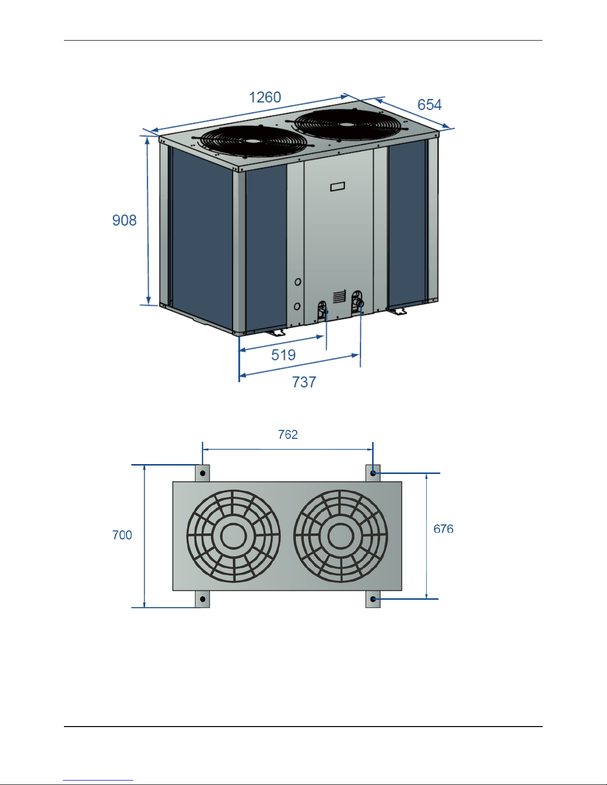
MCAC-UTSM-2012-12 R410A 50Hz Tropical Split AC
95
2.2 MOV-120HN1-C, MOV-120CN1-C
Page 96

R410A 50Hz Tropical Split AC MCAC-UTSM-2012-12
96
3. Service Space
3.1 MOV-76CN1-C, MOV-76HN1-C, MOV-96CN1-C, MOV-96HN1-C
MOV-120HN1-C, MOV-120CN1-C
Air outlet
Air inletAir inlet
≥1000 mm
≥1000 mm
≥500 mm
≥1000 mm
≥1000 mm
Note:
1. In case any obstacles exist above the outdoor unit, such obstacles must be 2000mm above the outdoor unit.
2. If miscellaneous articles are piled around the outdoor unit, such articles must be 400mm below the top of the outdoor unit.
Page 97

MCAC-UTSM-2012-12 R410A 50Hz Tropical Split AC
97
Foundation of the outdoor unit
762
676
≥500 mm
≥500 mm
M12 foundation bolt
4 screws for 1 unit
Page 98

R410A 50Hz Tropical Split AC MCAC-UTSM-2012-12
98
4. Wiring Diagrams
4.1 MOV-76CN1-C, MOV-96CN1-C, MOV-120CN1-C
Item
Name
Item
Name
Item
Name
Item
Name
COMP
Compressor
HEAT(A)
Crank
RT3A
Pipe temp. sensor
T1
Transformer
FAN1-2
Outdoor fan
CT1
Current detector
RT4
Room temp. sensor
SW1-3
Switch
CAP1-2
Fan capacitance
XT1-2
4-way terminal
XS1-5, XP1-5
Connectors
C1
Filter capacitor
S.V
4-way valve
XT3
3-way terminal
L-PRO(A)
Low pressure switch
KM1-2
Relay
KM(1)
AC contactor
H-PRO(A)
High pressure switch
K1
Temp. protect switch
CN8-208
P.C. board socket
XT4-10
Middle wire joint
- - - - -
-
Page 99

MCAC-UTSM-2012-12 R410A 50Hz Tropical Split AC
99
4.2 MOV-76HN1-C, MOV-96HN1-C, MOV-120HN1-C
Item
Name
Item
Name
Item
Name
Item
Name
COMP
Compressor
HEAT(A)
Crank
RT3A
Pipe temp. sensor
T1
Transformer
FAN1-2
Outdoor fan
CT1
Current detector
RT4
Room temp. sensor
SW1-3
Switch
CAP1-2
Fan capacitance
XT1-2
4-way terminal
XS1-5, XP1-5
Connectors
C1-3
Filter capacitor
S.V
4-way valve
XT3
3-way terminal
L-PRO(A)
Low pressure switch
KM1-2
Relay
KM(1)
AC contactor
H-PRO(A)
High pressure switch
K1
Temp. protect switch
CN8-208
P.C. board socket
XT4-10
Middle wire joint
- - - - -
-
Page 100

R410A 50Hz Tropical Split AC MCAC-UTSM-2012-12
100
5. Electric Characteristics
Model
Outdoor Unit
Power Supply
Compressor
OFM
Hz
Voltage
Min.
Max.
MCA
TOCA
MFA
MSC
RLA
KW
FLA
MOV-76C-C
50
380-415
342
438
17.5
18
20.5
86
16.5
0.573
2.613
MOV-76H-C
50
380-415
342
438
17.5
18
20.5
86
16.5
0.573
2.613
MOV-96C-C
50
380-415
342
438
20
21
23.8
110
20
1.373
6.26
MOV-96H-C
50
380-415
342
438
20
21
23.8
110
20
1.373
6.26
MOV-120C-C
50
380-400
342
440
25
28.6
30
147
21.4
1.373
6.26
MOV-120H-C
50
380-400
342
440
25
28.6
30
147
21.4
1.373
6.26
Remark:
MCA: Min. Current Amps. (A)
TOCA: Total Over-current Amps. (A)
MFA: Max. Fuse Amps. (A)
MSC: Max. Starting Amps. (A)
RLA: Rated Locked Amps. (A)
OFM: Outdoor Fan Motor.
FLA: Full Load Amps. (A)
KW: Rated Motor Output (kW)
 Loading...