

Page 1

MCAC-UTSM-12
1
Content
Part 1 General Information ........................................... 1
Part 2 Indoor Units ........................................................ 4
Part 3 Outdoor Units ................................................... 50
Part 4 Installation ........................................................ 65
Part 1 General Information
1. Model Names of Indoor/Outdoor Units ............................. 1
2. External Appearance .......................................................... 2
3. Nomenclature ................................................................ ..... 3
1. Model Names of Indoor/Outdoor Units
1.1 Model Names of Units with Cooling only:
Type
Indoor unit
Outdoor unit
Capacity
Model
Power
supply
Model
Power
supply
kW
kBtu/h
Floor-standing
type
MDFA-76CRN2
220~240V-
1N-50Hz
MOV-76C-CN2
380~415V-
3N-50Hz
22
76
MDFA-96CRN2
MOV-96C-CN2
28
96
Mid-static
pressure duct
type
MDTA-76CRN2
MOV-76C-CN2
22
76
MDTA-96CRN2
MOV-96C-CN2
28
96
MDTA-120CRN2
MOV-120C-CN2
380~400V-
3N-50Hz
35
120
Page 2
MCAC-UTSM-12
Type
Indoor unit
Capacity
Model
Power
supply
Model
Power
supply
kW
kBtu/h
Floor-standing
type
MDFA-76HRN2
220~240V-
1N-50Hz
MOV-76H-CN2
380~415V-
3N-50Hz
22
76
MDFA-96HRN2
MOV-96H-CN2
28
96
Mid-static
pressure duct
type
MDTA-76HRN2
MOV-76H-CN2
22
76
MDTA-96HRN2
MOV-96H-CN2
28
96
MDTA-120HRN2
MOV-120H-CN2
380~400V-
3N-50Hz
35
120
MDTA-76C(H)RN2
MDTA-96C(H)RN2
MDTA-120C(H)RN2
1.2 Model Names of Units with Cooling and heating:
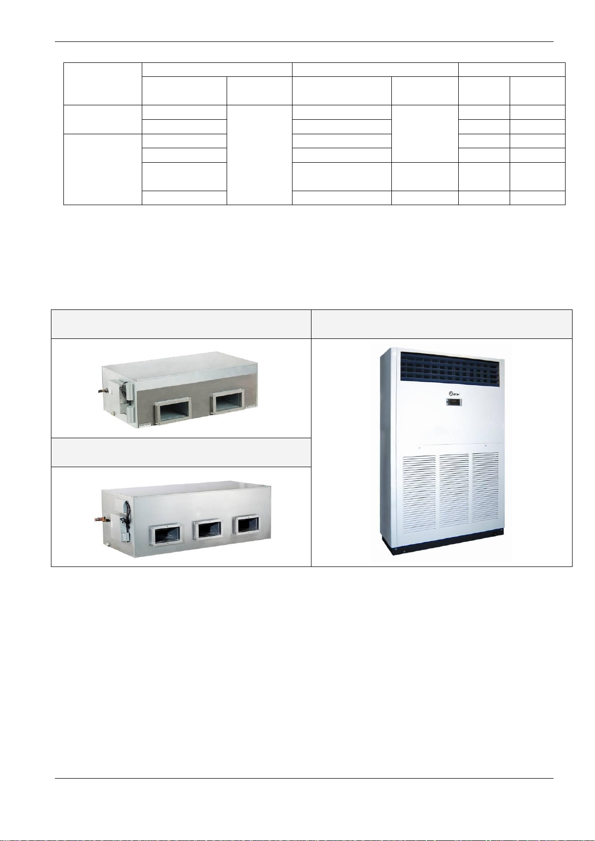
2. External Appearance
2.1 Indoor Units
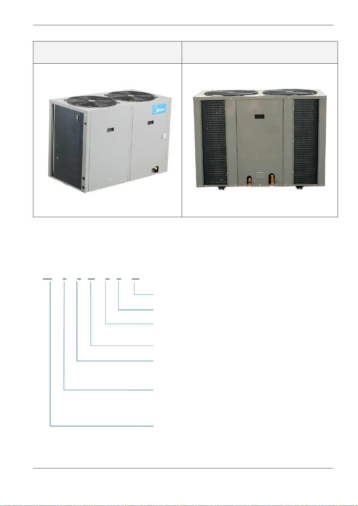
Outdoor unit
MDFA-76C(H)RN2
MDFA-96C(H)RN2
2
Page 3
MCAC-UTSM-12
MDOV-76C(H)-CN2
MDOV-96C(H)-CN2
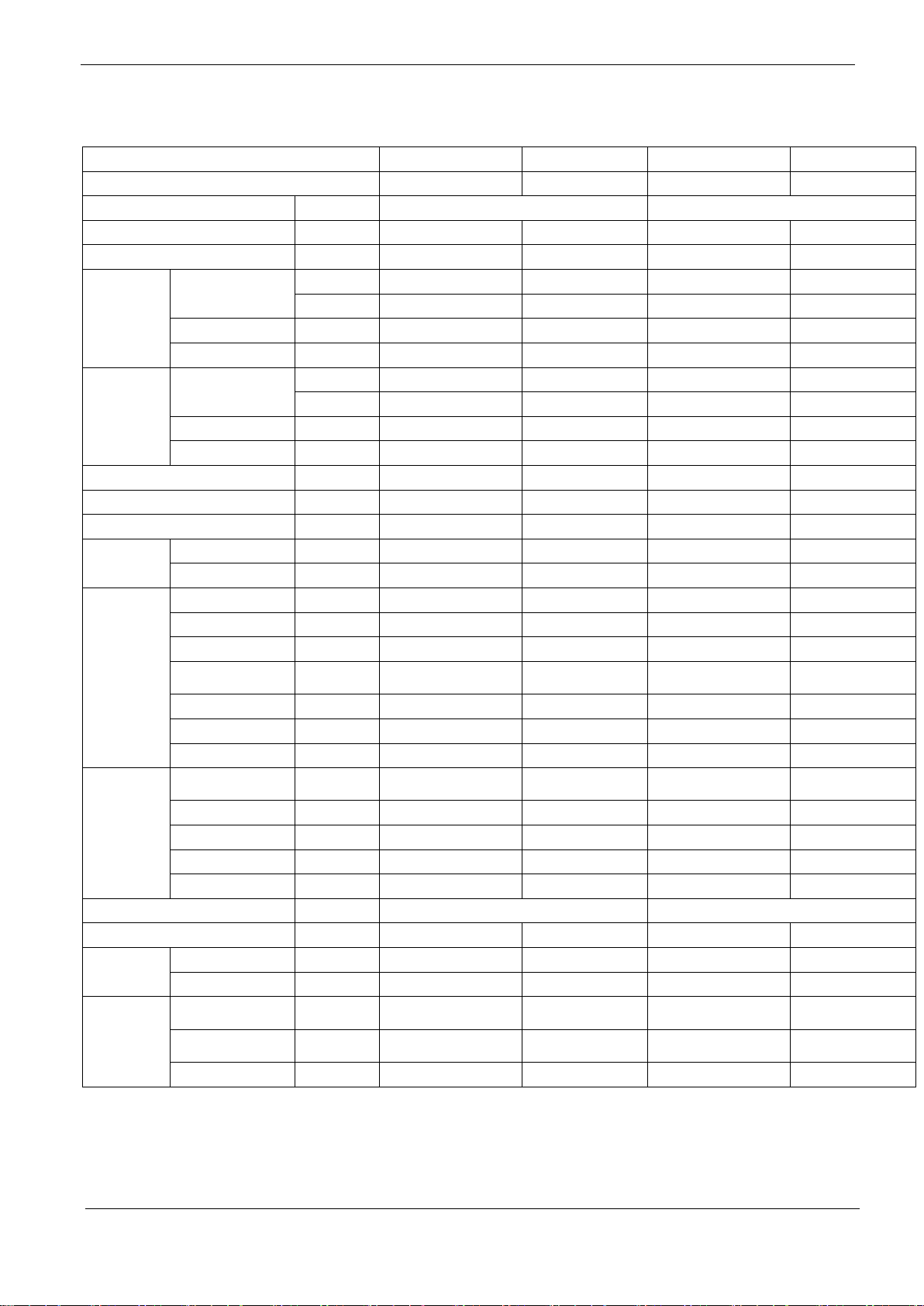
MD T A – 76 C R N2
N2:R407C;N1:R410a
R:Remote Controller
Function Code: C: Cooling
H: Cooling and Heating
Cooling Capacity (76 kBtu/h)
Product Series
A: 1st
time design
B: 2nd
time design
Indoor Units
T: Medium static pressure duct type
F: Floor-standing type
H: High static pressure duct type
MDV
2.2 Outdoor Unit
MDOV-120C(H)-CN2
3. Nomenclature
3.1 Indoor unit:
3
Page 4

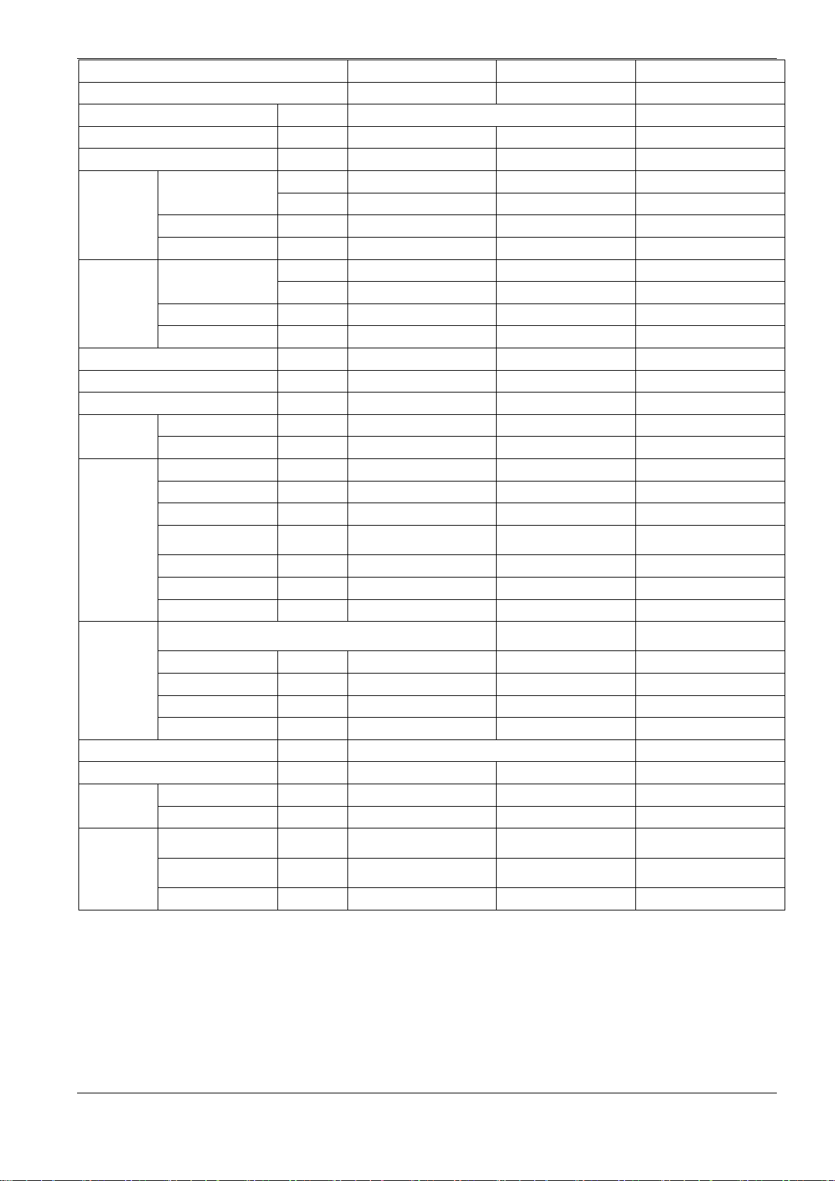
MD O V
76 C N2
3.2 Outdoor unit:
MCAC-UTSM-12
N2:R407C;
N1:R410a
Function Code:
C: Cooling Only
H: Heat pump
Cooling Capacity (76 kBtu/h)
Universal Outdoor Unit
Outdoor Unit
MDV
Part 2 Indoor Units
Duct Type ................................................................................ 4
Floor-standing Type ............................................................. 31
Duct Type
1. Features .............................................................................. 5
2. Specifications ..................................................................... 5
3. Dimensions ......................................................................... 8
4. Service Space ..................................................................... 9
5. Refrigerant cycle Diagrams ............................................. 11
6. Wiring Diagrams ............................................................... 11
7.Capacity Table ................................................................... 15
8. Static Pressure ................................................................. 21
9. Electric Characteristics ................................................... 22
10. Sound Levels .................................................................. 23
12. Troubleshooting.............................................................24
4
Page 5
Model
MDTA-76HRN2
MDTA-96CRN2
MDTA-96HRN2
Code
220070900191
220070900181
220070900171
Power supply
- 220~240V-1N-50Hz
220~240V-1N-50Hz
Rated input power
W 11500
11500 14500
14700
Rated current
A 20 20 28 28.1
Cooling
Capacity
Btu/h 75,100
75,100
92,800
91,400
W 22000
22000 27200
26800
Input
W 7500
7500 9200
9200
EER W/W
2.93
2.93 2.96
2.91
Heating
Capacity
Btu/h
——
83600
——
109500
W
——
24500
——
32100
Input
W
——
7320
——
9800
COP W/W
——
3.35
——
3.28
Indoor air flow
m3/h(CFM)
4650(2700)
4650(2700)
5600(3300)
5600(3300)
Indoor external static pressure
Pa
100 100 100
Indoor noise level
dB(A)
54 55 55
Refrigerant
Type -
Control -
Capillary
Capillary
Capillary
Fan
Type -
Centrifugal fan
Centrifugal fan
Centrifugal fan
Fan model
-
SYZ9-9MD
SYZ9-9MD
SYZ9-9MD
Dimension
mm
Φ307 Φ307
Φ307
Drive type/ Motor
step
-
Direct/ Single
Direct/ Single
Direct/ Single
Motor model
-
YDK300-4X
YDK550-4X
YDK550-4X
Motor Input * No.
W
720*2
1015*2
1015*2
Motor speed
rpm 1040
1040 1300
1300
Coil
Type -
Copper tube and
aluminum fin
Copper tube and
aluminum fin
Copper tube and
aluminum fin
Copper tube and
aluminum fin
Tube size
mm
Ф9.52
Ф9.52 Ф9.52
Ф9.52
No. of rows
- 4 4 4 4
Fin per inch
FPI 17 17 17 17
Length* height
mm 1200*406
1200*406
1200*406
1200*406
Controller -
Remote controller
Remote controller
Drain pipe size
mm
Ф41
Ф41 Ф41
Ф41
Connection
wiring
Power wiring
mm2
3*2.5
3*2.5 3*2.5
3*2.5
Signal wiring
mm2
2*1.0
4*1.0 2*1.0
4*1.0
Indoor unit
Dimension
(W*H*D)
mm 1350*450*760
1350*450*760
1350*450*760
1350*450*760
Packing
(W*H*D)
mm 1549*476*917
1549*476*917
1549*476*917
1549*476*917
Net/Gross weight
kg 105/120
105/120
105/120
105/120
2. Specifications
MCAC-UTSM-12
MDTA-76CRN2
220070900201
100
54
R407C
Capillary
Centrifugal fan
SYZ9-9MD
Φ307
R407C R407C R407C
Notes:
1. ESP: external static pressure
2. Nominal cooling capacities are based on the following conditions:
Indoor temp: 27°CDB, 19°CWB; Outdoor temp: 35°CDB, 24°CWB; Equivalent refrigerant piping: 7.5m (horizontal).
3. Nominal heating capacities are based on the following conditions:
Indoor temp: 20°CDB, 15°CWB; Outdoor temp: 7°CDB, 6°CWB; Equivalent refrigerant piping: 7.5m (horizontal).
6
Direct/ Single
YDK300-4X
720*2
Page 6
MCAC-UTSM-12
Model
MDTA-120HRN2
Code
220070900151
Power supply - 220~240V-1N-50Hz
Rated input power
W
18000
18000
Rated current A 28.7
28.7
Cooling
Capacity
Btu/h
116,000
116,000
W
34000
34000
Input
W
11900
11900
EER
W/W
2.86
2.86
Heating
Capacity
Btu/h
——
139900
W
——
41000
Input
W
——
12600
COP
W/W
——
3.25
Indoor air flow
m3/h
6800
6800
Indoor external static pressure
150
Indoor noise level
56
Refrigerant
Type
Control
Capillary
Fan
Type
Centrifugal fan
Fan model
SYZ9-9MD
Dimension
Φ307
Drive type/ Motor
step
Direct/ Single
Motor model
YDK300-4X
Motor Input * No.
720*3
Motor speed
rpm
1040/930/825
1040/930/825
Coil
Type
-
Copper tube and
aluminum fin
Copper tube and
aluminum fin
Tube size
mm
Ф7
Ф7
No. of rows - 4
4
Fin per inch
FPI
17
17
Length* height
mm
1602*588
1602*588
Controller
-
Remote controller
Drain pipe size
mm
Ф41
Ф41
Connection
wiring
Power wiring
mm2
3*2.5
3*2.5
Signal wiring
mm2
2*1.0
4*1.0
Indoor unit
Dimension
(W*H*D)
mm
1828*638*858
1828*638*858
Packing
(W*H*D)
mm
2095*689*929
2095*689*929
Net/Gross weight
kg
188/220
188/220
MDTA-120CRN2
220070900161
Pa 150
dB(A) 56
-
- Capillary
- Centrifugal fan
- SYZ9-9MD
mm Φ307
R407C R407C
- Direct/ Single
- YDK300-4X
W 720*3
Notes:
1. ESP: external static pressure
2. Nominal cooling capacities are based on the following conditions:
Indoor temp: 27°CDB, 19°CWB; Outdoor temp: 35°CDB, 24°CWB; Equivalent refrigerant piping: 7.5m (horizontal).
3. Nominal heating capacities are based on the following conditions:
Indoor temp: 20°CDB, 15°CWB; Outdoor temp: 7°CDB, 6°CWB; Equivalent refrigerant piping: 7.5m (horizontal).
7
Page 7
MCAC-UTSM-12
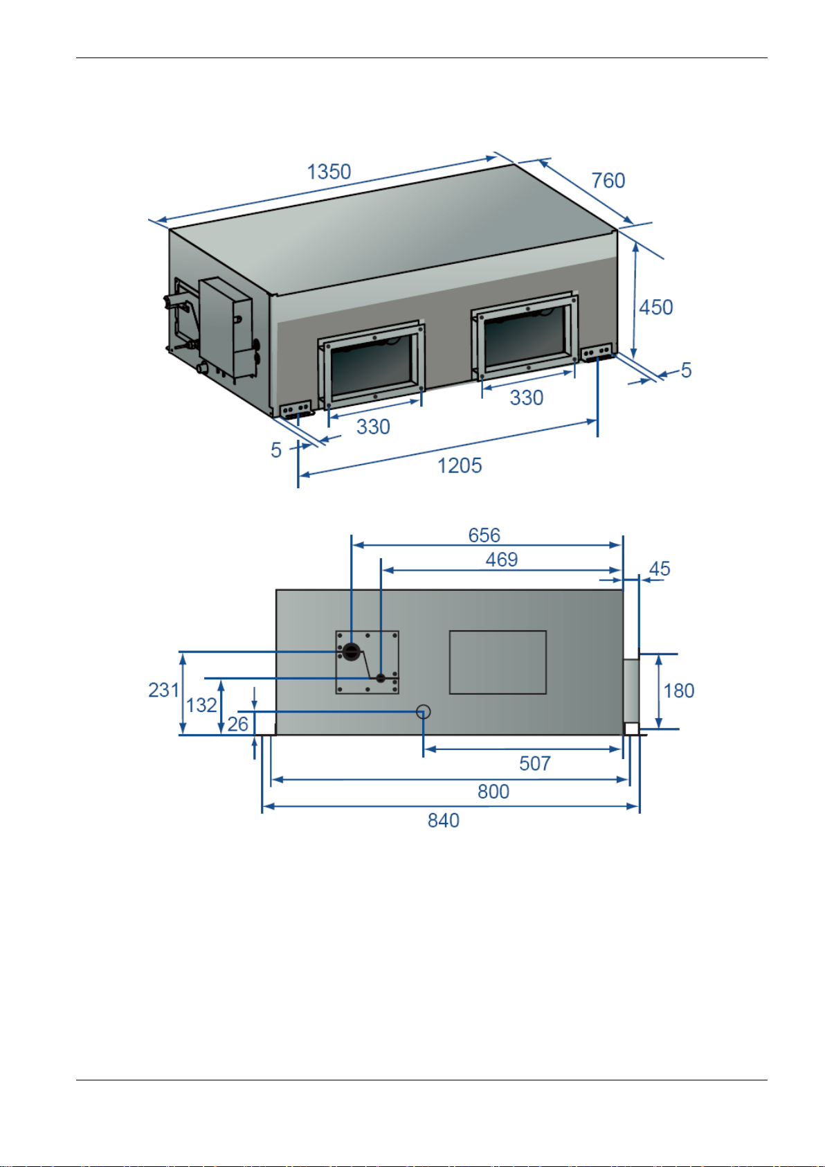
3. Dimensions
3.1 MDTA-76C(H)RN2, MDTA-96C(H)RN2
8
Page 8
MCAC-UTSM-12
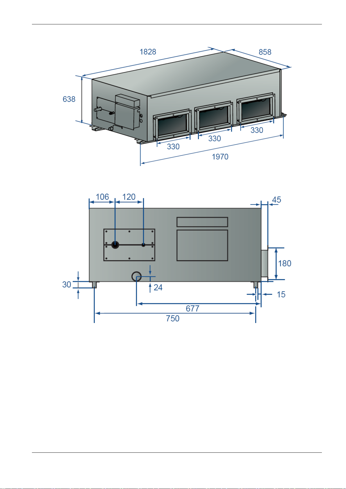
3.2 MDTA-120C(H)RN2
9
Page 9
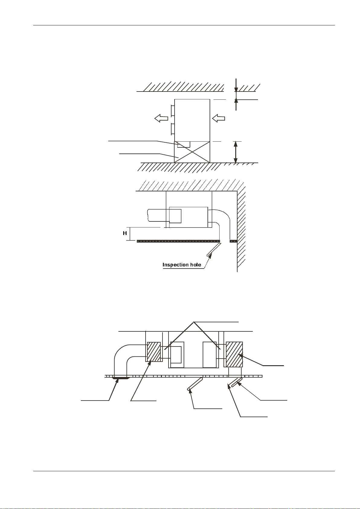
4. Service Space
MCAC-UTSM-12
m
m
0
0
5
≥
Electric control box
Inspection hole
m
m
0
0
6
≥
Top view Side view
10
ir outlet
Muffle
Canvas adapter
Inspection
Air duct system
hole
Air inlet
Air filter
Muffle
Page 10
MCAC-UTSM-12
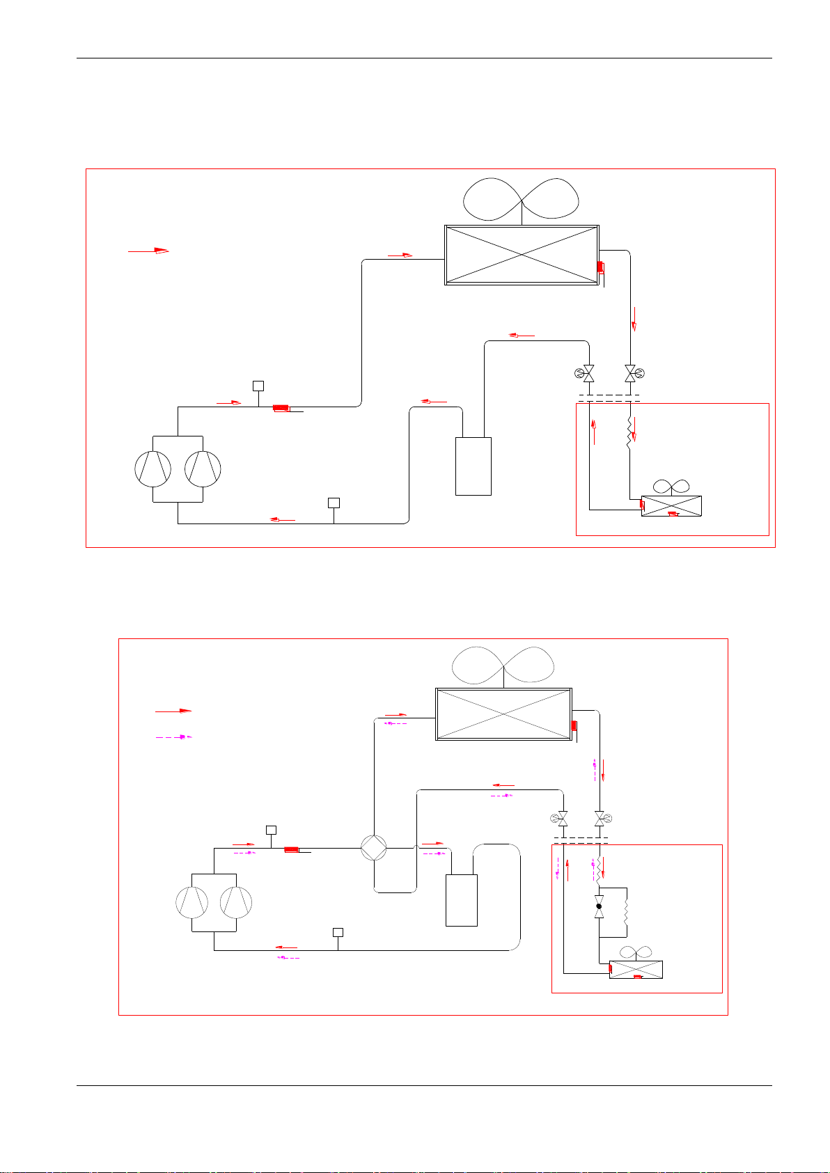
5. Refrigerant cycle diagrams
5.1 Cooling only: MDTA-76CRN2, MDTA-96CRN2, MDTA-120CRN2
Cooling
Outdoor heat-exchanger
HP Switch
Discharge temp. sensor
Compressors
LP Switch
Liquid-gas seperator
T3
Stop valve
5.3 Cooling and heating: MDTA-76HRN2, MDTA-96HRN2, MDTA-120HRN2
Stop valve
Indoor unit
Capillary
Indoor
heat-exchanger
T2
T4
Cooling
Heating
Outdoor heat-exchanger
HP Switch
4-way valve
Discharge temp. sensor
Compressors
LP Switch
Liquid-gas seperator
T3
Check valve
Stop valve
Capillary
Indoor unit
Indoor
heat-exchanger
Stop valve
T2
T4
11
Page 11
MCAC-UTSM-12
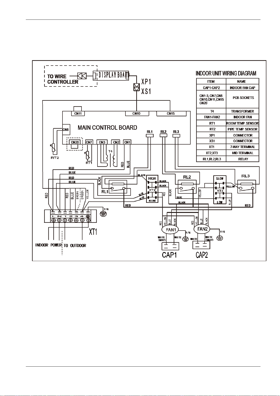
6. Wiring Diagrams
6.1 MDTA-76CRN2, MDTA-96CRN2
12
Page 12
MCAC-UTSM-12
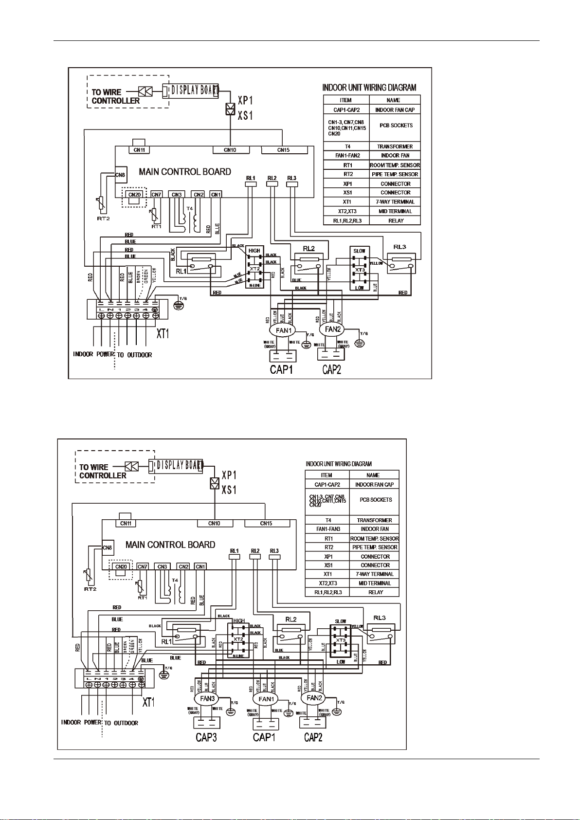
6.2 MDTA-76HRN2, MDTA-96HN2
6.3 MDTA-120CRN2
13
Page 13
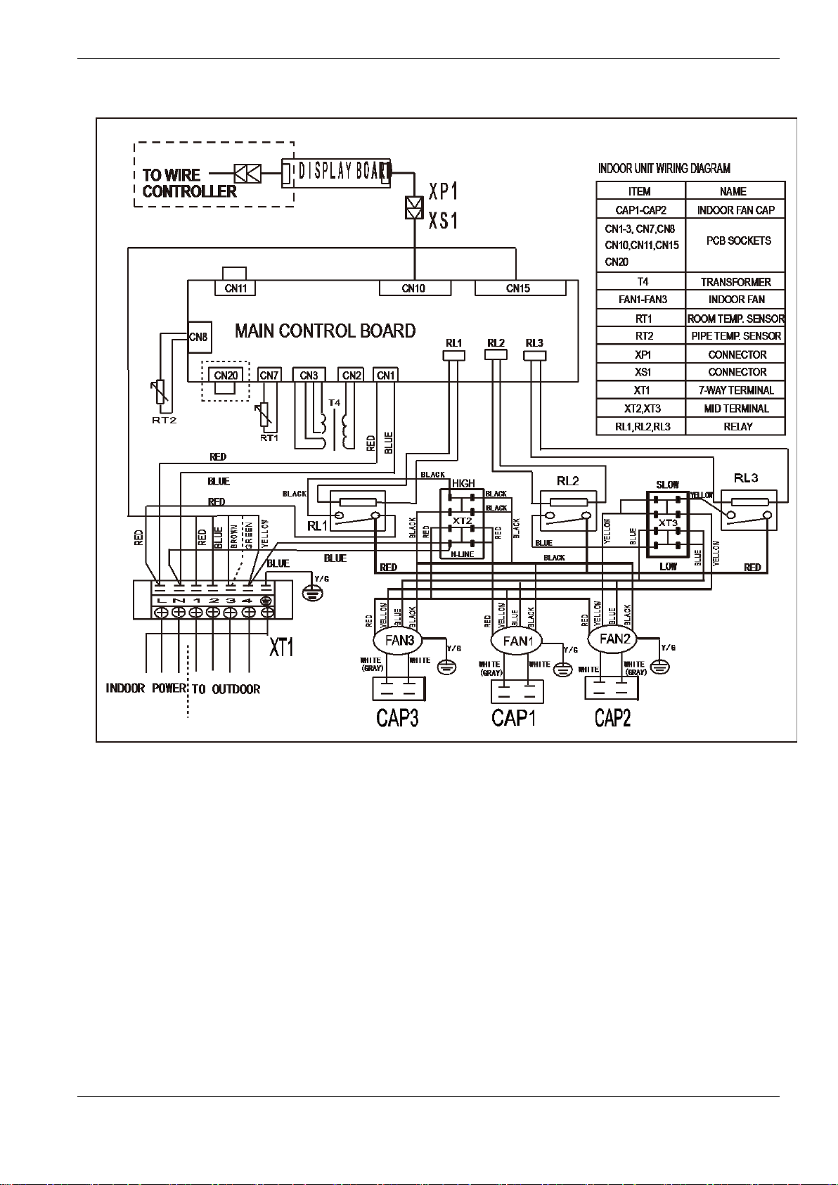
6.4 MDTA-120HRN2
MCAC-UTSM-12
14
Page 14
MCAC-UTSM-12
Gross Cooling Capacity (kW)
Outdoor DB(°C)
29.40
35.00
Indoor
WB(°C)
16.10
19.40
22.80
16.10
19.40
22.80
CFM
DB(°C)
TGC
SHC
PI
TGC
SHC
PI
TGC
SHC
PI
TGC
SHC
PI
TGC
SHC
PI
TGC
SHC
PI
2200
23.90
19.2
15.0
7.13
21.7
12.2
7.33
23.0
5.3
7.46
18.4
15.1
7.56
20.5
11.6
7.79
21.8
5.0
7.93
26.70
19.9
17.2
7.15
7.48
18.8
17.1
7.58
20.9
13.5
7.81
22.2
9.6
29.40
20.6
18.7
7.17
7.5
19.2
18.4
7.6
21.3
17.5
7.83
22.6
13.5
32.20
21.3
20.9
7.19
7.52
19.6
19.2
7.62
21.7
19.8
7.85
23.1
17.0
2500
23.90
20.3
16.2
7.33
7.66
19.4
16.3
7.76
21.1
12.2
7.99
22.4
5.3
26.70
21.0
18.3
7.35
7.68
19.8
18.3
7.78
21.5
15.3
8.01
22.8
10.0
29.40
21.7
20.1
7.37
7.7
20.2
19.8
7.8
21.9
18.4
8.03
23.3
14.2
32.20
22.5
21.4
7.39
23.6
21.9
7.59
25.1
18.7
7.72
20.6
20.6
7.82
22.4
20.7
8.05
23.7
17.7
8.19
2700
23.90
20.8
18.1
7.57
22.8
14.2
7.9
24.1
6.3
7.9
19.9
18.3
8
21.6
13.5
8.23
22.8
5.9
8.37
26.70
21.5
20.5
7.59
23.2
17.9
7.79
24.6
11.8
7.92
20.3
20.3
8.02
22.0
16.9
8.25
23.3
11.2
8.39
29.40
22.3
21.6
7.61
23.7
21.7
7.81
25.1
16.6
7.94
20.7
20.7
8.04
22.4
20.6
8.27
23.8
15.7
8.41
32.20
23.0
22.6
7.63
24.1
21.9
7.83
25.6
20.8
7.96
21.1
21.1
8.06
22.9
20.8
8.29
24.2
19.7
8.43
3000
23.90
21.3
18.8
7.88
23.2
13.9
8.08
24.6
6.0
8.21
20.7
18.3
8.31
22.1
13.2
8.54
23.3
5.7
8.68
26.70
22.0
21.2
7.9
23.7
17.4
8.1
25.1
11.4
8.23
21.1
20.3
8.33
22.5
16.5
8.56
23.8
10.8
8.7
29.40
22.8
22.1
7.92
24.2
21.0
8.12
25.6
16.2
8.25
21.5
21.5
8.35
23.0
20.0
8.58
24.3
15.4
8.72
32.20
23.6
23.1
7.94
24.7
23.7
8.14
26.1
20.2
8.27
22.0
22.0
8.37
23.4
22.5
8.6
24.8
19.2
8.74
7. Capacity Table
7.1 76 kBtu/h
22.1 14.3 7.35 23.5 10.1
22.5 18.5 7.37 24.0 14.3
23.0 20.9 7.39 24.4 18.0
22.3 12.9 7.53 23.6 5.6
22.7 16.1 7.55 24.1 10.6
23.2 19.5 7.57 24.6 15.0
7.95
7.97
7.99
8.13
8.15
8.17
15
Page 15
MCAC-UTSM-12
Gross Cooling Capacity (kW)
Outdoor DB(°C)
40.60
46.10
51.70
Indoor
WB(°C)
16.10
19.40
22.80
16.10
19.40
22.80
16.10
19.40
22.80
CFM
DB(°C)
TGC
SHC
PI
TGC
SHC
PI
TGC
SHC
PI
TGC
SHC
PI
TGC
SHC
PI
TGC
SHC
PI
TGC
SHC
PI
TGC
SHC
PI
TGC
SHC
PI
2200
23.9
18.41
15.09
8.49
19.98
11.29
8.73
21.25
4.91
8.88
16.9
13.9
8.68
18.4
10.4
8.94
19.6
4.5
9.19
16.1
13.2
10.67
17.3
9.8
11.03
18.4
4.3
11.28
26.7
18.78
17.07
8.51
20.38
13.2
8.75
21.68
9.34
8.9
17.3
15.7
8.7
18.8
12.2
8.96
20.0
8.6
9.21
16.4
14.9
10.7
17.7
11.5
11.06
18.8
8.1
11.31
29.4
19.16
18.42
8.53
20.79
17.04
8.77
22.11
13.16
8.92
17.6
17.0
8.72
19.2
15.7
8.98
20.4
12.1
9.23
16.7
16.1
10.73
18.0
14.8
11.09
19.2
11.4
11.34
32.2
19.54
19.16
8.55
21.2
19.28
8.79
17.8
9
20.8
15.3
9.26
17.0
16.7
10.75
18.4
16.7
11.12
19.5
2500
23.9
19.02
15.98
8.69
20.59
11.9
8.93
11.0
9.14
20.2
4.8
9.39
16.7
14.0
10.87
17.9
10.4
11.23
19.0
26.7
19.4
17.96
8.71
21
14.89
8.95
13.8
9.16
20.6
9.0
9.41
17.0
15.7
10.9
18.3
13.0
11.26
19.4
29.4
19.79
19.4
8.73
21.42
18
8.97
16.6
9.18
21.0
12.8
9.43
17.3
17.0
10.93
18.7
15.7
11.29
19.8
32.2
20.18
20.18
8.75
21.85
20.23
8.99
18.7
9.21
21.4
16.0
9.46
17.7
17.7
10.95
19.0
17.6
11.32
20.2
2700
23.9
19.51
17.9
8.39
21.08
13.17
8.78
12.2
9.38
20.7
5.4
9.63
17.2
15.7
11.11
18.4
11.5
11.47
19.5
26.7
19.9
19.9
8.41
21.5
16.54
8.65
15.3
9.4
21.1
10.1
9.65
17.5
17.5
11.14
18.8
14.5
11.5
19.9
29.4
20.3
20.3
8.43
21.93
20.12
8.67
23.26
15.4
8.82
18.8
18.8
9.16
20.3
18.6
9.42
21.5
14.3
9.67
17.9
17.9
11.17
19.2
17.6
11.53
20.3
13.4
11.78
32.2
20.7
20.7
8.45
22.37
20.34
8.69
23.72
19.29
8.84
19.1
19.1
9.19
20.7
18.8
9.45
22.0
17.9
9.7
18.2
18.2
11.2
19.6
17.8
11.56
20.7
16.8
11.81
3000
23.9
20
17.7
9.24
21.57
12.92
9.48
22.84
5.6
9.63
18.5
16.4
9.43
20.0
12.0
9.69
21.2
5.2
9.94
17.7
15.6
11.42
18.9
11.3
11.78
20.0
4.9
12.03
26.7
20.4
19.62
9.26
22
16.18
9.5
23.3
10.59
9.65
18.9
18.2
9.45
20.4
15.0
9.71
21.6
9.8
9.96
18.0
17.3
11.45
19.3
14.2
11.81
20.4
9.3
12.06
29.4
20.81
20.81
9.28
22.44
19.51
9.52
23.77
15.04
9.67
19.3
19.3
9.47
20.8
18.1
9.73
22.0
13.9
9.98
18.4
18.4
11.48
19.7
17.1
11.84
20.8
13.2
12.09
32.2
21.22
21.22
9.31
22.89
22.01
9.55
24.24
18.79
9.7
19.7
19.7
9.5
21.2
20.4
9.76
22.5
17.4
10.01
18.7
18.7
11.51
20.1
19.3
11.87
21.2
16.5
12.12
22.56 16.59 8.94 18.0 17.6 8.74 19.5
21.86 5.16 9.08 17.6 14.8 8.88 19.0
22.3 9.78 9.1 17.9 16.6 8.9 19.4
22.75 13.87 9.12 18.3 17.9 8.92 19.8
23.2 17.31 9.15 18.6 18.6 8.94 20.2
22.35 5.79 8.78 18.0 16.6 9.12 19.5
22.8 10.91 8.8 18.4 18.4 9.14 19.9
Notes:
1. DB = Dry Bulb Temperature (°C), WB = Wet Bulb Temperature (°C)
4. TGC = Total Cooling Capacity (kW)
5. SHC = Sensible Heating Capacity (kW)
6. PI = Power Input (kW)
14.4 11.37
4.5 11.48
8.5 11.51
12.1 11.54
15.1 11.57
5.1 11.72
9.5 11.75
16
Page 16

MCAC-UTSM-12
Gross Cooling Capacity (kW)
Outdoor DB(°C)
29.40
35.00
Indoor
WB(°C)
16.10
19.40
22.80
16.10
19.40
22.80
CFM
DB(°C)
TGC
SHC
PI
TGC
SHC
PI
TGC
SHC
PI
TGC
SHC
PI
TGC
SHC
PI
TGC
SHC
PI
2700
23.9
24.3
19.0
9.38
26.8
15.1
9.58
28.1
6.5
9.71
23.5
19.3
9.81
25.6
14.5
10.03
26.8
6.2
10.17
26.7
25.1
21.6
9.4
27.3
17.7
9.6
28.7
12.4
9.73
24.0
21.8
9.83
26.1
16.9
10.06
27.4
11.8
10.2
29.4
26.0
23.6
9.42
27.8
22.8
9.62
29.3
17.4
9.75
24.5
23.5
9.85
26.6
21.8
10.09
27.9
16.6
10.23
32.2
26.9
26.4
9.45
9.78
25.0
24.5
9.88
27.1
24.7
10.11
28.5
21.0
3000
23.9
25.3
20.3
9.58
9.91
24.5
20.6
10
26.2
15.1
10.23
27.5
6.5
26.7
26.2
22.8
9.6
9.93
25.0
23.2
10.03
26.7
18.9
10.26
28.0
12.3
29.4
27.1
25.1
9.62
9.95
25.5
25.0
10.06
27.2
22.9
10.29
28.6
17.4
32.2
28.1
26.7
9.65
9.98
26.0
26.0
10.08
27.8
25.7
10.31
29.1
21.7
3260
23.9
25.8
22.4
9.82
10.14
25.0
22.9
10.24
26.7
16.7
10.47
27.9
7.2
26.7
26.7
25.4
9.84
28.4
21.9
10.04
29.8
14.3
10.17
25.5
25.5
10.27
27.2
20.9
10.5
28.5
13.6
10.64
29.4
27.6
26.8
9.86
29.0
26.6
10.07
30.4
20.1
10.2
26.0
26.0
10.3
27.7
25.5
10.53
29.1
19.3
10.67
32.2
28.6
28.0
9.89
29.6
26.9
10.09
31.0
25.2
10.22
26.5
26.5
10.32
28.3
25.7
10.55
29.7
24.1
10.69
3500
23.9
26.3
23.3
10.12
28.3
17.0
10.32
29.7
7.3
10.45
25.8
22.8
10.55
27.2
16.3
10.78
28.4
7.0
10.92
26.7
27.2
26.2
10.15
28.9
21.3
10.35
30.3
13.8
10.48
26.3
25.3
10.58
27.7
20.4
10.81
29.0
13.2
10.95
29.4
28.2
27.3
10.18
29.5
25.6
10.38
30.9
19.6
10.51
26.8
26.8
10.61
28.3
24.6
10.84
29.6
18.7
10.98
32.2
29.1
28.6
10.2
30.1
28.9
10.4
31.5
24.4
10.53
27.4
27.4
10.63
28.8
27.7
10.86
30.2
23.4
11
7.1 96 kBtu/h
28.4 25.8 9.65 29.8 21.9
27.4 15.8 9.78 28.7 6.8
27.9 19.8 9.8 29.3 12.9
28.5 23.9 9.82 29.9 18.2
29.0 26.9 9.85 30.5 22.8
27.8 17.4 10.14 29.2 7.6
10.25
10.37
10.4
10.43
10.45
10.61
17
Page 17
MCAC-UTSM-12
Gross Cooling Capacity (kW)
Outdoor DB(°C)
40.60
46.10
51.70
Indoor
WB(°C)
16.10
19.40
22.80
16.10
19.40
22.80
16.10
19.40
22.80
CFM
DB(°C)
TGC
SHC
PI
TGC
SHC
PI
TGC
SHC
PI
TGC
SHC
PI
TGC
SHC
PI
TGC
SHC
PI
TGC
SHC
PI
TGC
SHC
PI
TGC
SHC
PI
2700
23.9
23.8
19.5
10.85
25.4
14.3
11.09
26.7
6.2
11.24
22.3
18.3
11.04
23.8
13.5
11.3
25.0
5.8
11.55
19.6
16.1
12.37
20.9
11.8
12.73
21.9
5.1
12.98
26.7
24.3
22.1
10.88
25.9
16.8
11.12
27.2
11.7
11.27
22.8
20.7
11.07
24.3
15.7
11.33
25.5
11.0
11.58
20.0
18.2
12.4
21.3
13.8
12.76
22.4
9.7
13.01
29.4
24.8
23.8
10.91
26.4
21.6
11.15
27.7
16.5
11.3
23.2
22.3
11.1
24.8
20.3
11.36
26.0
15.5
11.61
20.4
19.6
12.43
21.7
17.8
12.79
22.8
13.6
13.04
32.2
25.3
24.8
10.93
26.9
24.5
11.18
28.3
20.8
11.33
23.7
23.2
11.13
25.3
23.0
11.39
26.5
19.5
11.64
20.8
20.4
12.46
22.1
20.1
12.82
23.3
17.1
13.08
3000
23.9
24.4
20.5
11.05
26.0
15.0
11.29
14.1
11.5
25.6
6.0
11.75
20.2
17.0
12.57
21.5
12.4
12.93
22.6
26.7
24.9
23.1
11.08
26.5
18.8
11.32
17.7
11.53
26.1
11.5
11.78
20.6
19.1
12.6
21.9
15.5
12.96
23.0
29.4
25.4
24.9
11.11
27.0
22.7
11.35
21.3
11.56
26.6
16.2
11.81
21.0
20.6
12.63
22.3
18.8
12.99
23.5
32.2
25.9
25.9
11.14
27.6
25.5
11.38
24.0
11.59
27.2
20.3
11.84
21.4
21.4
12.66
22.8
21.1
13.02
23.9
3260
23.9
24.9
22.9
11.29
26.5
16.5
11.68
15.6
11.74
26.1
6.8
11.99
20.7
19.0
12.81
22.0
13.7
13.17
23.0
26.7
25.4
25.4
11.32
27.0
20.8
11.56
19.5
11.77
26.6
12.7
12.02
21.1
21.1
12.84
22.4
17.2
13.2
23.5
29.4
25.9
25.9
11.35
27.5
25.3
11.59
28.9
19.1
11.74
24.4
24.4
11.54
25.9
23.8
11.8
27.1
18.0
12.05
21.5
21.5
12.87
22.9
21.0
13.23
24.0
15.9
13.48
32.2
26.4
26.4
11.38
28.1
25.5
11.62
29.4
23.9
11.77
24.9
24.9
11.57
26.4
24.0
11.83
27.7
22.5
12.08
22.0
22.0
12.9
23.3
21.2
13.27
24.5
19.9
13.52
3500
23.9
25.4
22.5
11.6
27.0
16.1
11.84
28.2
6.9
11.99
23.9
21.2
11.79
25.4
15.2
12.05
26.6
6.5
12.3
21.2
18.7
13.12
22.5
13.4
13.48
23.5
5.8
13.73
26.7
25.9
24.9
11.63
27.5
20.2
11.87
28.8
13.1
12.02
24.4
23.5
11.82
25.9
19.0
12.08
27.1
12.3
12.33
21.6
20.8
13.15
22.9
16.8
13.51
24.0
10.9
13.76
29.4
26.4
26.4
11.66
28.1
24.4
11.9
29.4
18.6
12.05
24.9
24.9
11.85
26.4
23.0
12.11
27.6
17.5
12.36
22.0
22.0
13.18
23.4
20.3
13.54
24.5
15.5
13.79
32.2
27.0
27.0
11.69
28.6
27.5
11.93
30.0
23.2
12.08
25.4
25.4
11.88
27.0
25.9
12.14
28.2
21.9
12.39
22.5
22.5
13.22
23.8
22.9
13.58
25.0
19.4
13.83
27.3 6.4 11.44 22.9 19.3 11.24 24.4
27.8 12.2 11.47 23.4 21.7 11.27 24.9
28.4 17.3 11.5 23.9 23.4 11.3 25.4
28.9 21.6 11.53 24.4 24.4 11.33 25.9
27.8 7.2 11.68 23.4 21.5 11.48 24.9
28.3 13.5 11.71 23.9 23.9 11.51 25.4
Notes:
1. DB = Dry Bulb Temperature (°C), WB = Wet Bulb Temperature (°C)
4. TGC = Total Cooling Capacity (kW)
5. SHC = Sensible Heating Capacity (kW)
6. PI = Power Input (kW)
18
5.3 13.18
10.1 13.21
14.3 13.24
17.9 13.28
6.0 13.42
11.2 13.45
Page 18
MCAC-UTSM-12
Gross Cooling Capacity (kW)
Outdoor DB(°C)
29.40
35.00
Indoor
WB(°C)
16.10
19.40
22.80
16.10
19.40
22.80
CFM
DB(°C)
TGC
SHC
PI
TGC
SHC
PI
TGC
SHC
PI
TGC
SHC
PI
TGC
SHC
PI
TGC
SHC
PI
3300
23.9
30.8
24.1
11.97
33.4
18.9
12.17
34.8
8.0
12.3
30.2
24.8
12.4
32.2
18.2
12.63
33.5
7.7
12.77
26.7
31.9
27.5
12
34.1
22.1
12.2
35.5
15.3
12.33
30.8
28.0
12.43
32.9
21.3
12.66
34.2
14.7
12.8
29.4
33.0
30.0
12.03
34.8
28.5
12.23
36.2
21.5
12.36
31.4
30.2
12.46
33.5
27.5
12.69
34.9
20.8
12.83
32.2
34.2
33.5
12.06
12.39
32.0
31.4
12.49
34.2
31.1
12.72
35.6
26.2
3700
23.9
31.9
25.5
12.17
12.5
31.2
26.2
12.6
32.8
19.0
12.83
34.1
8.1
26.7
33.0
28.7
12.2
12.53
31.8
29.4
12.63
33.5
23.8
12.86
34.8
15.3
29.4
34.2
31.6
12.23
12.56
32.4
31.8
12.66
34.2
28.7
12.89
35.5
21.6
32.2
35.4
33.7
12.26
12.59
33.1
33.1
12.69
34.9
32.3
12.92
36.2
27.0
4000
23.9
32.4
28.2
12.41
12.74
31.7
29.1
12.84
33.3
20.8
13.07
34.6
9.0
26.7
33.5
31.9
12.44
35.2
27.1
12.64
36.6
17.5
12.77
32.3
32.3
12.87
34.0
26.2
13.1
35.3
16.9
13.24
29.4
34.7
33.7
12.47
35.9
32.9
12.67
37.3
24.7
12.8
33.0
33.0
12.9
34.7
31.8
13.13
36.0
23.9
13.27
32.2
35.9
35.2
12.5
36.6
33.3
12.7
38.1
31.0
12.83
33.6
33.6
12.93
35.4
32.2
13.17
36.7
29.9
13.31
4500
23.9
32.9
29.1
12.72
35.0
21.0
12.92
36.4
8.9
13.05
32.5
28.7
13.15
33.8
20.3
13.38
35.1
8.6
13.52
26.7
34.0
32.7
12.75
35.7
26.3
12.95
37.1
16.9
13.08
33.1
31.8
13.18
34.5
25.4
13.41
35.8
16.3
13.55
29.4
35.2
34.2
12.78
36.4
31.7
12.98
37.8
24.0
13.11
33.8
33.8
13.21
35.2
30.6
13.44
36.5
23.1
13.58
32.2
36.4
35.7
12.81
37.1
35.7
13.01
38.6
29.9
13.15
34.4
34.4
13.25
35.9
34.5
13.48
37.3
28.9
13.62
7.3 120 kBtu/h
35.5 32.2 12.26 36.9 27.1
34.0 19.7 12.37 35.4 8.4
34.7 24.6 12.4 36.1 15.8
35.4 29.7 12.43 36.8 22.5
36.1 33.4 12.46 37.6 28.0
34.5 21.6 12.74 35.9 9.3
12.86
12.97
13
13.03
13.07
13.21
19
Page 19
MCAC-UTSM-12
Gross Cooling Capacity (kW)
Outdoor DB(°C)
40.60
46.10
51.70
Indoor
WB(°C)
16.10
19.40
22.80
16.10
19.40
22.80
16.10
19.40
22.80
CFM
DB(°C)
TGC
SHC
PI
TGC
SHC
PI
TGC
SHC
PI
TGC
SHC
PI
TGC
SHC
PI
TGC
SHC
PI
TGC
SHC
PI
TGC
SHC
PI
TGC
SHC
PI
3300
23.9
29.8
24.4
14.37
31.4
17.7
14.61
32.6
7.5
14.76
28.3
23.2
14.56
29.8
16.8
14.82
31.0
7.2
15.07
29.5
24.2
16.36
30.8
17.4
16.72
31.8
7.4
16.97
26.7
30.4
27.6
14.41
32.0
20.7
14.65
33.3
14.3
14.8
28.9
26.3
14.6
30.4
19.7
14.86
31.6
13.6
15.11
30.1
27.4
16.4
31.4
20.3
16.76
32.5
14.0
17.01
29.4
31.0
29.8
14.45
32.6
26.7
14.69
34.0
20.2
14.84
29.5
28.3
14.64
31.0
25.4
14.9
32.2
19.2
15.15
30.7
29.5
16.44
32.0
26.2
16.8
33.1
19.7
17.05
32.2
31.6
31.0
14.48
33.3
30.3
14.72
34.6
25.5
14.87
30.1
29.5
14.67
31.6
28.7
14.93
32.9
24.2
15.19
31.3
30.7
16.48
32.7
29.7
16.84
33.8
24.9
17.1
3700
23.9
30.4
25.5
14.57
32.0
18.5
14.81
30.4
17.6
15.02
31.6
7.5
15.27
30.1
25.3
16.56
31.4
18.1
16.92
32.5
26.7
31.0
28.7
14.61
32.6
23.1
14.85
31.0
22.0
15.06
32.2
14.1
15.31
30.7
28.4
16.6
32.0
22.7
16.96
33.1
29.4
31.6
31.0
14.65
33.3
27.9
14.89
31.6
26.6
15.1
32.8
20.0
15.35
31.3
30.7
16.64
32.6
27.4
17
33.8
32.2
32.3
32.3
14.68
33.9
31.4
14.92
32.3
29.9
15.14
33.5
25.0
15.39
31.9
31.9
16.68
33.3
30.8
17.04
34.4
4000
23.9
30.9
28.3
14.27
32.5
20.3
14.66
30.9
19.3
15.26
32.1
8.3
15.51
30.6
28.1
16.8
31.9
19.9
17.16
32.9
26.7
31.5
31.5
14.31
33.1
25.5
14.55
31.5
24.2
15.3
32.7
15.7
15.55
31.2
31.2
16.84
32.5
25.0
17.2
33.6
29.4
32.1
32.1
14.35
33.8
31.0
14.59
35.1
23.2
14.74
30.6
30.6
15.08
32.1
29.5
15.34
33.4
22.1
15.59
31.8
31.8
16.88
33.2
30.4
17.24
34.3
22.7
17.49
32.2
32.8
32.8
14.38
34.4
31.3
14.62
35.8
29.1
14.77
31.2
31.2
15.12
32.8
29.8
15.38
34.0
27.7
15.63
32.5
32.5
16.92
33.8
30.7
17.29
35.0
28.4
17.54
4500
23.9
31.4
27.8
15.12
32.9
19.7
15.36
34.2
8.4
15.51
29.9
26.5
15.31
31.4
18.8
15.57
32.6
8.0
15.82
31.1
27.5
17.11
32.4
19.4
17.47
33.4
8.2
17.72
26.7
32.0
30.8
15.16
33.6
24.7
15.4
34.9
15.9
15.55
30.5
29.3
15.35
32.0
23.5
15.61
33.2
15.1
15.86
31.7
30.5
17.15
33.0
24.3
17.51
34.1
15.5
17.76
29.4
32.6
32.6
15.2
34.3
29.8
15.44
35.6
22.5
15.59
31.1
31.1
15.39
32.6
28.4
15.65
33.9
21.4
15.9
32.3
32.3
17.19
33.7
29.3
17.55
34.8
22.0
17.8
32.2
33.3
33.3
15.24
35.0
33.6
15.48
36.3
28.2
15.63
31.7
31.7
15.43
33.3
32.0
15.69
34.5
26.8
15.94
33.0
33.0
17.24
34.3
33.0
17.6
35.5
27.5
17.85
33.2 7.8 14.96 28.9 24.3 14.76
33.9 14.9 15 29.5 27.3 14.8
34.6 21.1 15.04 30.1 29.5 14.84
35.3 26.3 15.08 30.7 30.7 14.87
33.7 8.7 14.66 29.4 27.0 15
34.4 16.5 14.7 30.0 30.0 15.04
Notes:
1. DB = Dry Bulb Temperature (°C), WB = Wet Bulb Temperature (°C)
4. TGC = Total Cooling Capacity (kW)
5. SHC = Sensible Heating Capacity (kW)
6. PI = Power Input (kW)
20
7.7 17.17
14.5 17.21
20.6 17.25
25.7 17.3
8.5 17.41
16.1 17.45
Page 20
MCAC-UTSM-12
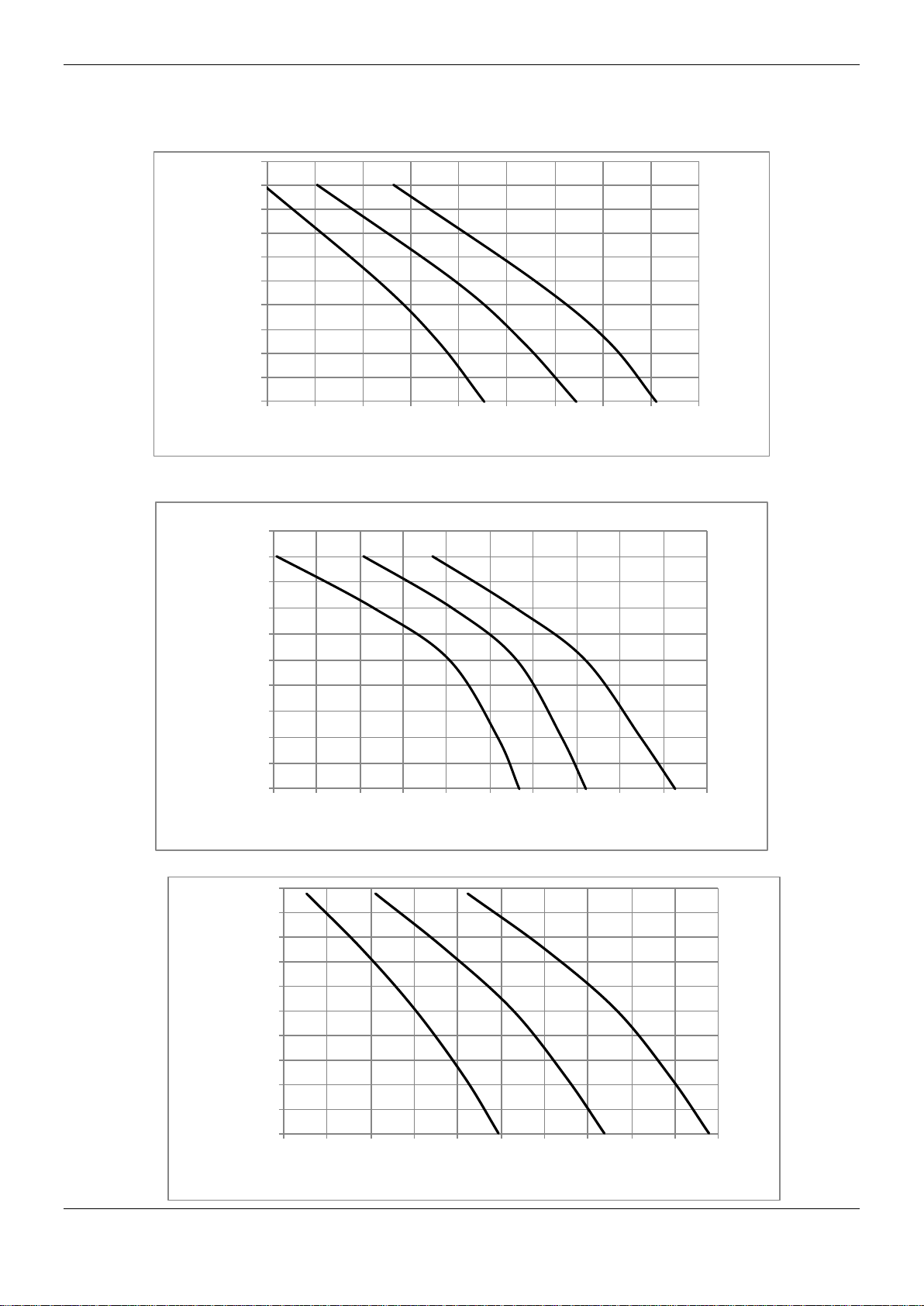
8. Air flow rate- Static pressure curve
8.1 76kBtu/h
8.2 96kBtu/h
200
180
160
140
120
100
Static Pressure (Pa)
Low
80
60
40
20
0
3250 3500 3750 4000 4250 4500 4750 5000
Medium
High
AirFlow (m3/h)
5250 5500
8.3 120kBtu/h
200
180
160
140
120
100
Static Pressure (Pa)
Low
80
60
40
20
0
3800 4050 4300 4550 4800 5050 5300 5550 5800 6050 6300
Medium
High
AirFlow (m3/h)
200
180
160
140
120
100
80
60
40
Static Pressure (Pa)
20
0
5000 5300 5600 5900 6200 6500 6800 7100 7400 7700 8000
Low
Medium
High
Air Flow (m3/h)
21
Page 21
MCAC-UTSM-12
Model
Indoor Unit
Power Supply
IFM
Hz Voltage
MCA
MFA kW FLA
MDTA-76CRN2
50 220-240
10
8
1.42
6.66
MDTA-76HRN2
50 220-240
10
8
1.42
6.66
MDTA-96CRN2
50 220-240
10
12
1.8 8.6
MDTA-96HRN2
50 220-240
10
12
1.8 8.6
MDTA-120CRN2
50 220-240
11.25
20
2.1 10
MDTA-120HRN2
50 220-240
198 254 11.25
20
2.1 10
Model
Outdoor Unit
Power Supply
Compressor
OFM
Hz Voltage
Min.
Max. MCA
TOCA MFA
MSC RLA KW FLA MDOV-76C-CN2
50 380-415
342 438 15.75
18.5 21.85
48*2 6.3*2
0.573
2.613
MDOV-76H-CN2
50 380-415
342 438 15.75
18.5 21.85
48*2 6.3*2
0.573
2.613
MDOV-96C-CN2
50 380-415
342 438 20 28 30 53*2 8.0*2 0.573
2.613
MDOV-96H-CN2
50 380-415
342 438 20 28 30 53*2 8.0*2 0.573
2.613
MDOV-120C-CN2
50 380-415
342 438 22.75
28.7 32.55
57*2 9.1*2 1.2
5.857
MDOV-120H-CN2
50 380-415
342 438 22.75
28.7 32.55
57*2 9.1*2 1.2
5.857
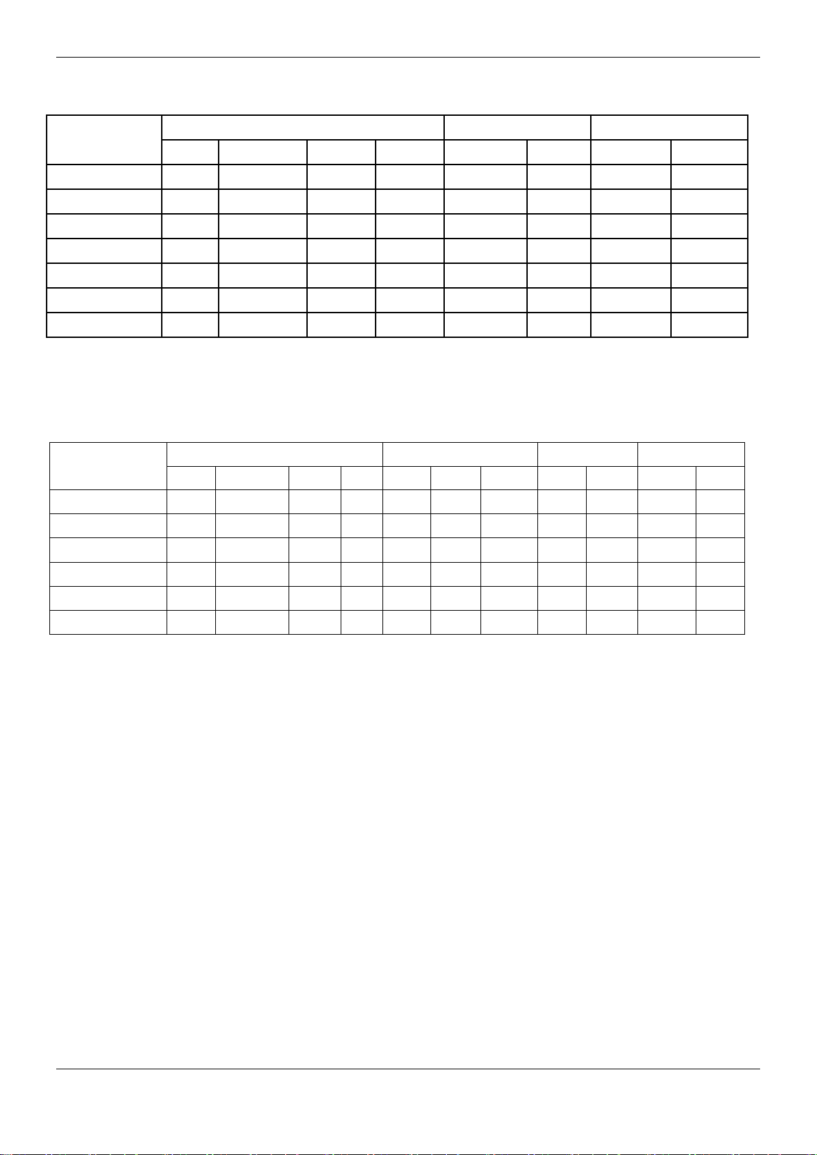
9. Electric Characteristics
Note:
MCA: Min. Current Amps. (A)
MFA: Max. Fuse Amps. (A)
IFM: Indoor Fan Motor
kW: Fan Motor Rated Output (kW)
FLA: Full Load Amps. (A)
Min.
198
198
198
198
198
Max.
254
254
254
254
254
Note:
MCA: Min. Current Amps. (A) TOCA: Total Over-current Amps. (A)
MFA: Max. Fuse Amps. (A) MSC: Max. Starting Amps. (A)
RLA: Rated Locked Amps. (A) OFM: Outdoor Fan Motor
KW: Rated Motor Output (KW) FLA: Full Load Amps. (A)
22
Page 22
MCAC-UTSM-12
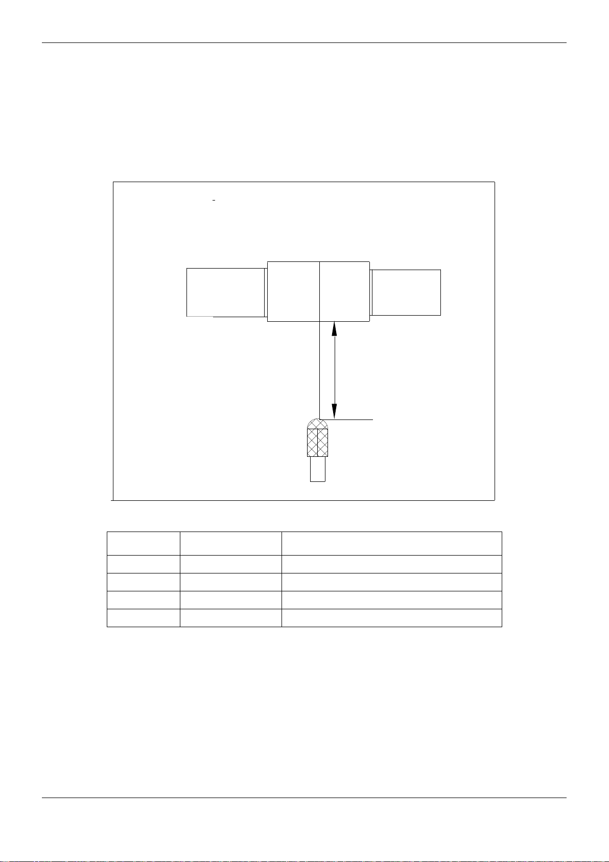
Unit Number
Model
Noise level under three speeds of fan (dB(A))
1
MDTA-76C(H)RN2
54
2
MDTA-96C(H)RN2
55
3
MDTA-120C(H)RN2
56
10. Sound Levels
Concealed Duct Type
Discharge
Duct
Suction
1.4m
Microphone
23
Page 23
MCAC-UTSM-12
f
Type
ALARM
Light
Remarks
Room temp. sensor error
- Manual reset
Evaporator temp. sensor error
☆
- - - Manual reset
Condenser temp. sensor error
- -
☆
- Manual reset
Water pump temp. sensor error
☆
- -
☆
Manual reset
The PRO terminal on PCB of
indoor unit without connected to
grounding wire
☆ ☆ ☆ ☆
Manual reset
EEPROM error
☆ ☆
- - Manual reset
Condensing water level full error
- - -
☆
Manual reset
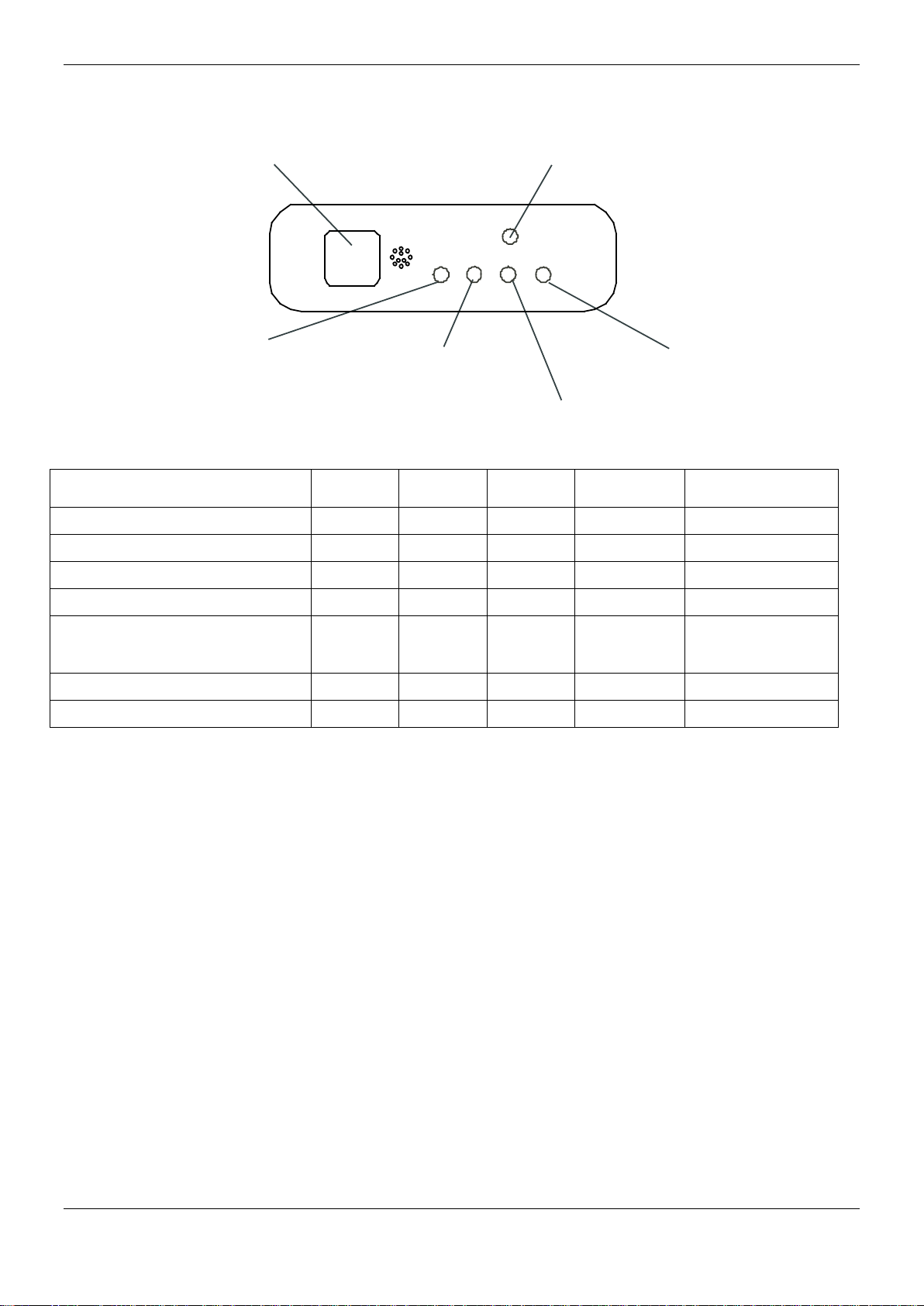
12. Troubleshooting
rared signal receiver
In
Manual Switch
Operation lamp
Timer lamp
PRE-DEF lamp(cooling and heating type)
or fan only lamp(cooling only type)
OPT.
Light
-
TME.
Light
☆
Note:
OPT. Light: operation light; TME. Light: timer light;
DEF. Light: defrosting light; ☆: the light flashing.
Alarm lamp
DEF.
Light
-
13.1 Malfunctions of air conditioner
If any of the following malfunctions occur, stop operation of the air conditioner immediately. Turn off the power
switch, and contact the local after sales service center of manufacturer:
The RUN lamp flashes quickly (2 flash per second).
After turning off the power switch and then turning it on again, the RUN lamp still flashes quickly.
The receiving function of the remote controller fails, or the start/ shutdown operation is abnormal.
The fuse blows out frequently, or the circuit breaker protection occurs frequently.
Obstacles or water enter the air conditioner.
Condensing water leaks from indoor unit.
Other malfunctions occur.
24
Page 24
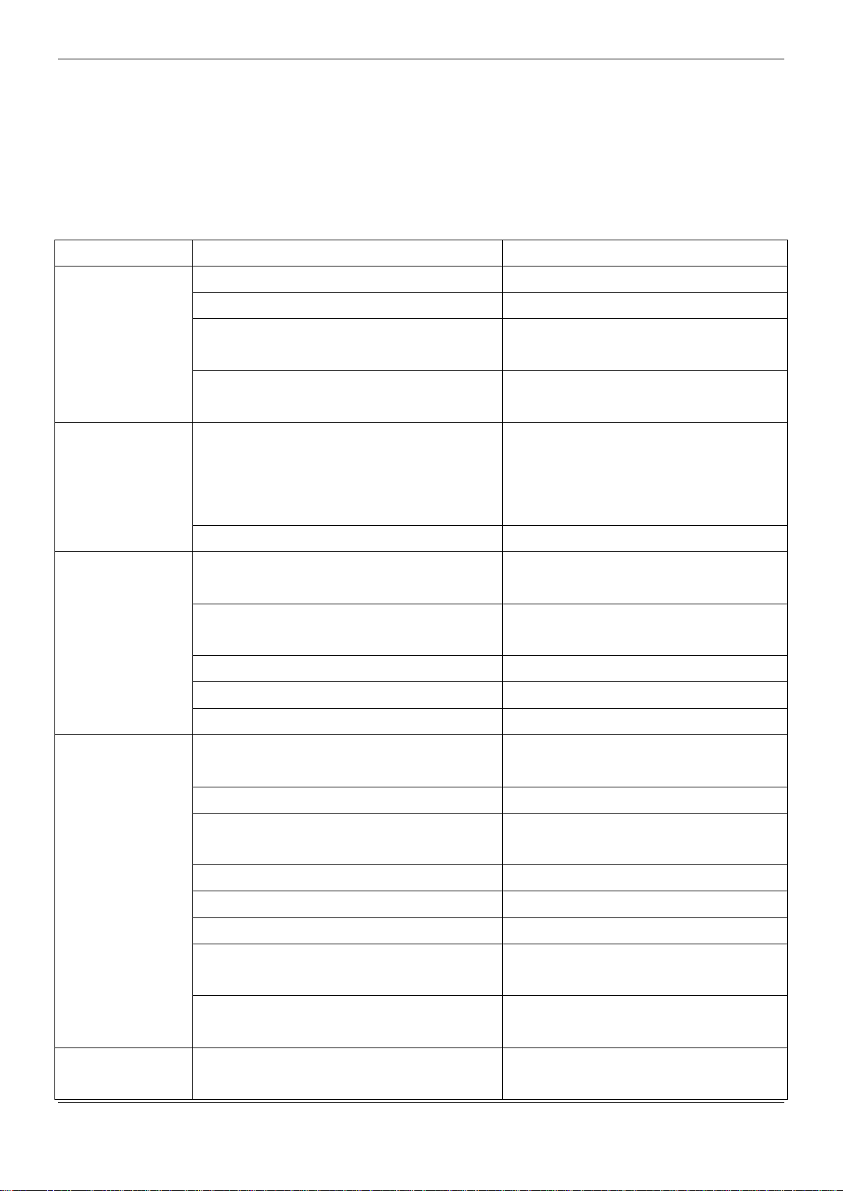
MCAC-UTSM-12
Symptoms
Causes
Handling methods
The unit does not
work
Power supply fails.
Operate after power resumes.
Power switch is not connected.
Connect the power supply properly.
Fuse blows out or circuit breaker snaps off.
Replace the fuse or check whether
electric leakage occurs.
The remote controller or the wire controller
fails.
Check the remote controller or wire
controller.
Air flowing
normally but
completely can’t
cooling
Temperature setting is improper.
Temperature setting is higher than the
room temperature in cooling mode. Or
temperature setting is lower than the
room temperature in heating mode.
3-minute protection of compressor.
Waiting for 3 minutes.
The unit starts or
stops frequently
The system is lack of refrigerant. Or there is
too much refrigerant in the system.
Fix the leakage places, and charge the
proper quantity of refrigerant.
Air or non-condensable gas exists in the
refrigerant system.
Vacuum the system and charge
refrigerant again.
Compressor fails.
Repair or replace the compressor.
The voltage is too high or too low.
Install a voltage regulator.
The refrigerant pipe is obstructed.
Locate and replace that part.
Poor cooling effect
The heat exchanger of outdoor unit or indoor
unit is too dirty.
Clean the heat exchanger.
The filter is too dirty.
Clean the filter.
Air inlet or air outlet of the indoor/ outdoor
unit is blocked.
Remove obstacles to keep well
ventilating.
Doors or windows of the room are open.
Close all the windows and doors.
Directly exposed to sunlight.
Use curtain to obstruct sunlight.
Too many heat sources in the room.
Reduce the heat sources.
The outdoor ambient temperature is too
high.
The cooling effect is poor but normal.
The system is lack of refrigerant.
Fix the leakage places, and charge the
proper quantity of refrigerant.
Poor heating
effect
The outdoor ambient temperature is lower
than -7℃.
Use an assistance heating device.
If the air conditioner fails and does not meet the above phenomena, check the system as the following table:
25
Page 25
Doors or windows of the room are not closed
tightly.
Close the doors and windows properly.
The system is lack of refrigerant.
Fix the leakage places, and charge the
proper quantity of refrigerant.
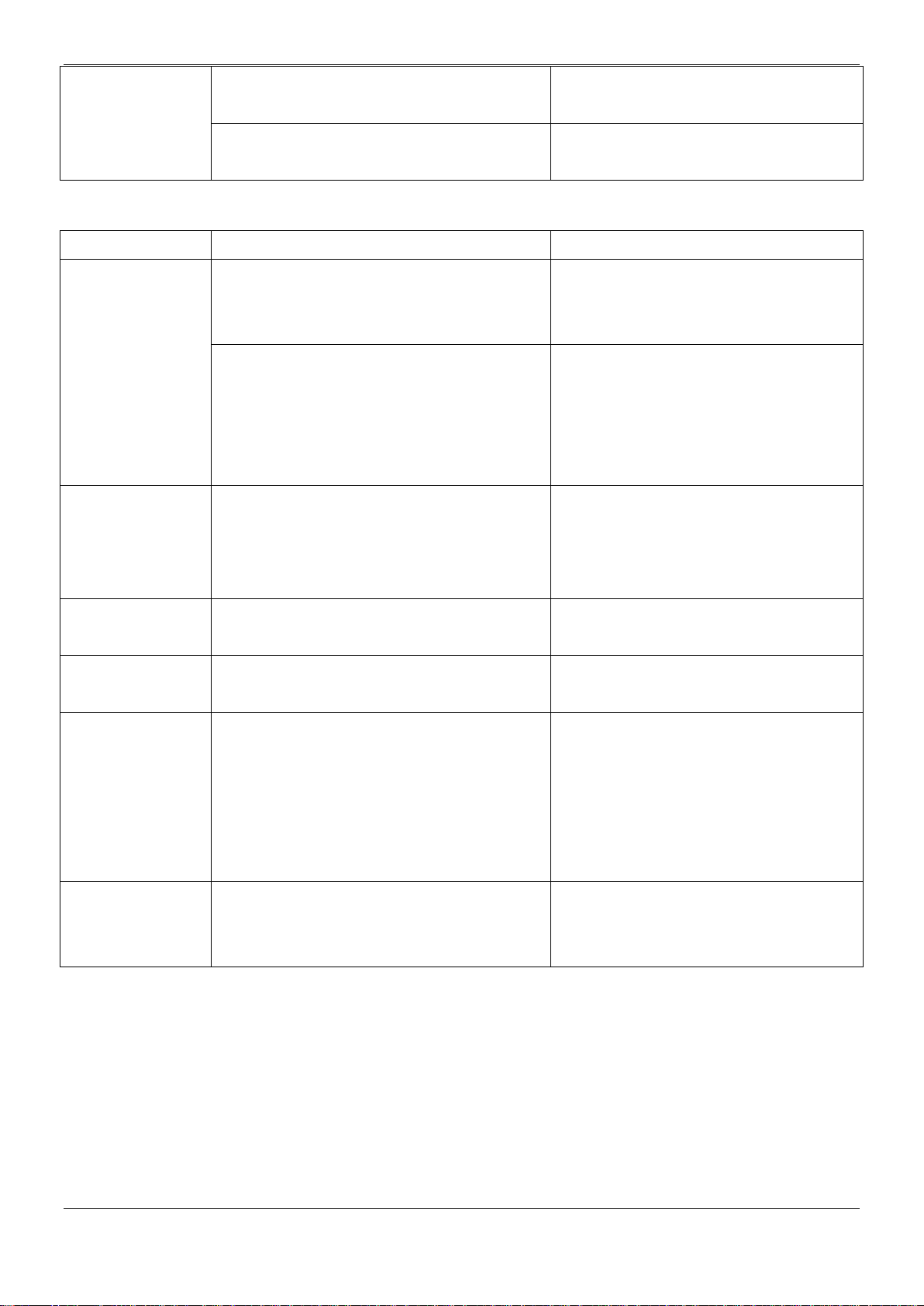
Symptoms
Causes
Handling methods
The fan speed
cannot be
changed
Check whether the mode marked on the
screen is “AUTO”.
When the “AUTO” mode is selected, the
unit will change the fan speed
automatically.
Check whether the mode marked on the
screen is “DEWET”.
When the “DEWET” mode is selected,
the unit will change the fan speed
automatically. The fan speed can be
selected in “COOLING”,”HEATING”
and ”SUPPLY AIR” mode.
The “ON/OFF”
button of remote
controller do not
work
Check whether the batteries of remote
controller are exhausted.
Replace the batteries.
The “ON/OFF”
lamp extinguishes
Check whether the time set on the timer has
expired.
Restart the unit.
The “TIMER ON”
lamp extinguishes
Check whether the time set on the timer has
expired.
It comes to the setting time and the unit
stat running automatically.
No receiving
sounds from the
indoor unit even
when the
“ON/OFF” button
is pressed
Check whether the signal transmitter of the
remote controller is properly directed to the
infrared signal receiver of the indoor unit
when the “ON/OFF” button is pressed.
Directly transmit the signal transmitter of
the remote controller to the infrared
signal receiver of the indoor unit, and
then push the “ON/OFF” button twice.
The buttons of the
remote controller
do not work
Check whether the settings are locked.
Push the “LOCK” button again.
MCAC-UTSM-12
26
Page 26
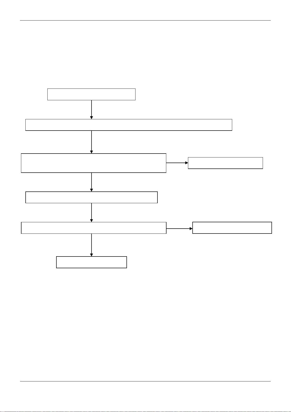
MCAC-UTSM-12
No
No
Yes
All lamps flashing at 5Hz
Judge 1: The PRO terminal on PCB of indoor unit without connecting to grounding wire
Validate: Check whether the PRO terminal on PCB of indoor
unit without connected to grounding wire.
Connect it to grounding wire.
Judge 2: Optical coupler on PCB malfunction
Validate: Check whether the Optical coupler is normal.
Replace optical coupler
Replace indoor PCB.
Operation lamp flashes:
Yes
27
Page 27
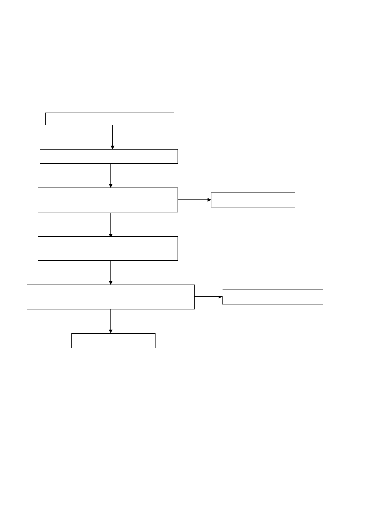
MCAC-UTSM-12
Timer lamp flashing at 5Hz
Room temperature sensor malfunction
Judge 1: Check the room temperature sensor
Is break off.
Connects it well.
Judge 2: Check the room temperature sensor
is abnormal.
Validate: Check whether the resistance of the
temperature sensor is correct according to Annex 1.
Replace temperature sensor
Replace indoor PCB.
No
Yes
No
Operation lamp flashes:
Yes
28
Page 28

MCAC-UTSM-12
Yes
No
Yes
Replace temperature sensor
Operation lamp flashing at 5Hz
Evaporate temperature sensor is abnormal.
Judge 1: Check evaporate temperature sensor is break off.
Judge 2: Evaporate temperature sensor is abnormal.
Validate: Check whether the resistance of the room
temperature sensor is correct according to Annex 1.
Replace temperature sensor
Replace indoor PCB.
Operation lamp flashes:
No
29
Page 29

Defrosting lamp flashing at 5Hz
Condenser temperature sensor malfunction
Judge 1: Check condenser temperature sensor is break off.
Replace temperature sensor
Yes
Judge 2: Condenser temperature sensor is abnormal.
Validate: Check whether the resistance of the condenser
temperature sensor is correct according to Annex 1.
Replace temperature sensor
No
Yes
Replace indoor PCB.
Operation lamp flashes:
MCAC-UTSM-12
No
30
Page 30

MCAC-UTSM-12
Floor-standing Type
1. Features ............................................................................ 32
2. Specifications .................................................................. 33
3. Dimensions ...................................................................... 34
4. Service Space .................................................................. 35
5. Refrigerant cycle diagrams ............................................. 36
6. Wiring Diagrams .............................................................. 37
7. Capacity Tables ................................................................ 39
8. Electric Characteristics ................................................... 43
9. Sound Levels ................................................................... 44
10. Exploded View .......... Ошибка! Закладка не определена.
11. Troubleshooting ............................................................. 45
12. Accessories ............... Ошибка! Закладка не определена.
31
Page 31

1. Features
MCAC-UTSM-12
1. The appearance is novel, luxurious, refined.
2. High capacity of cooling/heating, efficient, and energy-saving.
3. Adopt advanced and high efficient scroll compressor, wide angle and long distance air supply.
4. Remote control standard, screen control optional.
5. Easy installation and maintenance.
6. Suit for hotel, meeting room, airport lounge, etc. public occasion use.
32
Page 32

MCAC-UTSM-12
Model
MDFA-76CRN2
MDFA-76HRN2
MDFA-96CRN2
MDFA-96HRN2
Code
220043900081
220043900071
220043900061
220043900051
Power supply
-
220~240V-1Ph-50Hz
220~240V-1Ph-50Hz
Rated input power
W
11500
11500
14500
14700
Rated current
A
28
28.1
Cooling
Capacity
Btu/h
94,500
92,100
W
27700
27000
Input
W
9280
9450
EER
W/W
2.98
2.86
Heating
Capacity
Btu/h
——
103700
W
——
30400
Input
W
——
9130
COP
W/W
——
3.33
Indoor air flow
m3/h
4500
4500
Indoor noise level
dB(A)
54
54
Refrigerant
Type
-
Control - Capillary
Capillary
Capillary
Capillary
Fan
Type - Centrifugal fan
Centrifugal fan
Centrifugal fan
Centrifugal fan
Fan model
YSK300-6
YSK300-6
YSK300-6
YSK300-6
Dimension
mm
Φ250
Φ250
Φ250
Φ250
Drive type/ Motor
step
-
Direct/ Single
Direct/ Single
Direct/ Single
Direct/ Single
Motor model
-
YSK300-6
YSK300-6
YSK300-6
YSK300-6
Motor input* No.
W
590
590
590
590
Motor speed(Hi)
rpm
870
870
870
870
Coil
Type
-
Copper tube and
aluminum fin
Copper tube and
aluminum fin
Copper tube and
aluminum fin
Copper tube and
aluminum fin
Tube size
mm
Ф9.52
Ф9.52
Ф9.52
Ф9.52
No. of rows - 3 3 3
3
Fin per inch
FPI
16
16
16
16
Length* height
mm
982*711
982*711
982*711
982*711
Controller - Remote controller
Remote controller
Drainage water pipe dia.
mm
Ф41
Ф41
Ф41
Ф41
Connection
wiring
Power wiring
mm2
3×2.5
3×2.5
3×2.5
3×2.5
Signal wiring
mm2
2×1.0
4×1.0
2×1.0
4×1.0
Indoor unit
Dimension
(WxHxD)
mm
1200*1860*420
1200*1860*420
1200*1860*420
1200*1860*420
Packing
(W*H*D)
mm
1362*2023*582
1362*2023*582
1362*2023*582
1362*2023*582
Net/Gross weight
kg
158/174
158/174
158/174
158/174
2. Specifications
18.5 18.5
75,100 75,100
22000 22000
7450 7450
2.95 2.95
—— 83600
—— 24500
—— 6500
—— 3.77
4500 4500
53 53
R407C R407C R407C R407C
33
Page 33

MCAC-UTSM-12
Notes:
1. Nominal cooling capacities are based on the following conditions:
Indoor temp: 27°CDB, 19°CWB; Outdoor temp: 35°CDB; Equivalent ref. piping: 7.5m (horizontal)
2. Nominal heating capacities are based on the following conditions:
Indoor temp: 20°CDB; Outdoor temp: 7°CDB, 6°CWB; Equivalent ref. piping: 7.5m (horizontal)
3. Dimensions
34
Page 34

MCAC-UTSM-12
4. Service Space
Front view
m
c
0
1
m
c
0
1
30 cm
No obstacle in front of it
Rear
35
Page 35

MCAC-UTSM-12
5. Refrigerant cycle diagrams
5.1 Cooling only: MDFA-76CRN2, MDFA-96CRN2
Cooling
Outdoor heat-exchanger
HP Switch
Discharge temp. sensor
Compressors
LP Switch
Liquid-gas seperator
5.2 Cooling and heating: MDFA-76HRN2, MDFA-96HRN2
Cooling
Stop valve
T3
Stop valve
Indoor unit
Capillary
Indoor
heat-exchanger
T2
T4
36
Heating
HP Switch
Discharge temp. sensor
Compressors
LP Switch
4-way valve
Outdoor heat-exchanger
Liquid-gas seperator
T3
Check valve
Stop valve
Capillary
Indoor unit
Indoor
heat-exchanger
Stop valve
T2
T4
Page 36

MCAC-UTSM-12
6. Wiring Diagrams
6.1 MDFA-76CRN2, MDFA-96CRN2
CN20CN20CN20
37
Page 37

MCAC-UTSM-12
6.2 MDFA-76HRN2, MDFA-96HRN2
CN20CN20CN20
38
Page 38

MCAC-UTSM-12
Gross Cooling Capacity (kW)
Outdoor DB(°C)
29.40
35.00
Indoor
WB(°C)
16.10
19.40
22.80
16.10
19.40
22.80
CFM
DB(°C)
TGC
SHC
PI
TGC
SHC
PI
TGC
SHC
PI
TGC
SHC
PI
TGC
SHC
PI
TGC
SHC
PI
2125
23.9
19.6
16.1
6.33
21.7
12.2
6.53
23.0
5.3
6.66
18.8
15.4
6.76
20.5
11.6
6.99
21.8
5.0
7.13
26.7
20.3
18.4
6.35
22.1
14.3
6.55
23.5
10.1
6.68
19.2
17.4
6.78
20.9
13.5
7.01
22.2
9.6
7.15
29.4
21.0
20.2
6.37
6.7
19.6
18.8
6.8
21.3
17.5
7.03
22.6
13.5
32.2
21.7
21.3
6.38
6.71
20.0
19.6
6.81
21.7
19.8
7.05
23.1
17.0
2310
23.9
20.2
17.0
6.53
6.86
19.4
16.3
6.96
21.1
12.2
7.19
22.4
5.3
26.7
20.9
19.4
6.55
6.88
19.8
18.3
6.98
21.5
15.3
7.21
22.8
10.0
29.4
21.6
21.2
6.57
6.9
20.2
19.8
7
21.9
18.4
7.23
23.3
14.2
32.2
22.4
22.4
6.58
6.91
20.6
20.6
7.01
22.4
20.7
7.25
23.7
17.7
2650
23.9
20.7
19.0
6.77
22.8
14.2
7.1
24.1
6.3
7.1
19.9
18.3
7.2
21.6
13.5
7.43
22.8
5.9
7.57
26.7
21.4
21.4
6.79
23.2
17.9
6.99
24.6
11.8
7.12
20.3
20.3
7.22
22.0
16.9
7.45
23.3
11.2
7.59
29.4
22.2
22.2
6.81
23.7
21.7
7.01
25.1
16.6
7.14
20.7
20.7
7.24
22.4
20.6
7.47
23.8
15.7
7.61
32.2
22.9
22.9
6.82
24.1
21.9
7.02
25.6
20.8
7.16
21.1
21.1
7.26
22.9
20.8
7.49
24.2
19.7
7.63
7. Capacity Tables
7.1 76kBtu/h
22.5 18.5 6.57 24.0 14.3
23.0 20.9 6.58 24.4 18.0
22.3 12.9 6.73 23.6 5.6
22.7 16.1 6.75 24.1 10.6
23.2 19.5 6.77 24.6 15.0
23.6 21.9 6.78 25.1 18.7
7.17
7.19
7.33
7.35
7.37
7.39
39
Page 39

MCAC-UTSM-12
Gross Cooling Capacity (kW)
Outdoor DB(°C)
40.60
46.10
51.70
Indoor
WB(°C)
16.10
19.40
22.80
16.10
19.40
22.80
16.10
19.40
22.80
CFM
DB(°C)
TGC
SHC
PI
TGC
SHC
PI
TGC
SHC
PI
TGC
SHC
PI
TGC
SHC
PI
TGC
SHC
PI
TGC
SHC
PI
TGC
SHC
PI
TGC
SHC
PI
2125
23.9
18.3
15.0
7.59
19.9
11.2
7.83
21.2
4.9
7.98
16.8
13.8
7.78
18.3
10.4
8.04
19.5
4.5
8.29
16.1
13.2
9.68
17.3
9.8
10.03
18.4
4.3
10.28
26.7
18.7
17.0
7.61
20.3
13.1
7.85
21.6
9.3 8 17.2
15.6
7.8
18.7
12.1
8.06
19.9
8.6
8.31
16.4
14.9
9.7
17.7
11.5
10.06
18.8
8.1
10.31
29.4
19.1
18.3
7.63
20.7
17.0
7.87
22.0
13.1
8.02
17.5
16.9
7.82
19.1
15.6
8.08
20.3
12.1
8.33
16.7
16.1
9.72
18.0
14.8
10.09
19.2
11.4
10.34
32.2
19.4
19.1
7.65
21.1
19.2
19.4
17.7
8.1
20.7
15.2
8.35
17.0
16.7
9.75
18.4
16.7
10.11
19.5
2310
23.9
18.9
15.9
7.79
20.5
11.8
18.9
10.9
8.24
20.1
4.7
8.49
16.7
14.0
9.88
17.9
10.4
10.23
19.0
26.7
19.3
17.9
7.81
20.9
14.8
19.3
13.7
8.26
20.5
9.0
8.51
17.0
15.7
9.9
18.3
13.0
10.26
19.4
29.4
19.7
19.3
7.83
21.3
17.9
19.7
16.5
8.28
20.9
12.8
8.53
17.3
17.0
9.92
18.7
15.7
10.29
19.8
32.2
20.1
20.1
7.85
21.7
20.1
20.1
18.6
8.3
21.3
15.9
8.55
17.7
17.7
9.95
19.0
17.6
10.31
20.2
2650
23.9
19.4
17.8
7.49
21.0
13.1
19.4
12.1
8.48
20.6
5.3
8.73
17.2
15.7
10.11
18.4
11.5
10.47
19.5
26.7
19.8
19.8
7.51
21.4
16.5
19.8
15.2
8.5
21.0
10.1
8.75
17.5
17.5
10.14
18.8
14.5
10.5
19.9
29.4
20.2
20.2
7.53
21.8
20.0
7.77
23.2
15.3
7.92
18.7
18.7
8.26
20.2
18.5
8.52
21.4
14.2
8.77
17.9
17.9
10.17
19.2
17.6
10.53
20.3
13.4
10.78
32.2
20.6
20.6
7.55
22.3
20.2
7.79
23.6
19.2
7.94
19.0
19.0
8.28
20.6
18.7
8.54
21.9
17.8
8.79
18.2
18.2
10.19
19.6
17.8
10.55
20.7
16.8
10.8
7.89 22.5 16.5 8.04 17.9 17.5 7.84
8.03 21.8 5.1 8.18 17.5 14.7 7.98
8.05 22.2 9.7 8.2 17.8 16.5 8
8.07 22.6 13.8 8.22 18.2 17.8 8.02
8.09 23.1 17.2 8.24 18.5 18.5 8.04
7.88 22.3 5.8 7.88 17.9 16.5 8.22
7.75 22.7 10.9 7.9 18.3 18.3 8.24
Notes:
1. DB = Dry Bulb Temperature (°C), WB = Wet Bulb Temperature (°C)
4. TGC = Total Cooling Capacity (kW)
5. SHC = Sensible Heating Capacity (kW)
6. PI = Power Input (kW)
14.4 10.36
4.5 10.48
8.5 10.51
12.1 10.54
15.1 10.56
5.1 10.72
9.5 10.75
40
Page 40

MCAC-UTSM-12
Gross Cooling Capacity (kW)
Outdoor DB(°C)
29.40
35.00
Indoor
WB(°C)
16.10
19.40
22.80
16.10
19.40
22.80
CFM
DB(°C)
TGC
SHC
PI
TGC
SHC
PI
TGC
SHC
PI
TGC
SHC
PI
TGC
SHC
PI
TGC
SHC
PI
2125
23.9
25.1
20.6
8.23
27.2
15.4
8.43
28.6
6.6
8.56
24.4
20.0
8.66
26.1
14.7
8.89
27.3
6.3
9.03
26.7
26.0
23.6
8.25
8.58
24.9
22.6
8.68
26.6
17.2
8.91
27.9
12.0
29.4
26.9
25.9
8.27
8.6
25.4
24.4
8.7
27.1
22.2
8.93
28.4
16.9
32.2
27.8
27.3
8.29
8.62
25.9
25.4
8.72
27.7
25.1
8.95
29.0
21.3
2310
23.9
25.7
21.6
8.43
8.76
25.0
21.0
8.86
26.7
15.4
9.09
27.9
6.6
26.7
26.6
24.6
8.45
8.78
25.5
23.6
8.88
27.2
19.3
9.11
28.5
12.5
29.4
27.5
27.0
8.47
8.8
26.0
25.5
8.9
27.7
23.3
9.13
29.1
17.7
32.2
28.5
28.5
8.49
8.82
26.5
26.5
8.92
28.3
26.2
9.16
29.7
22.1
2650
23.9
26.2
24.0
8.67
28.3
17.7
9
29.7
7.7 9 25.5
23.4
9.1
27.2
17.0
9.33
28.4
7.4
9.47
26.7
27.1
27.1
8.69
28.9
22.2
8.89
30.3
14.5
9.02
26.0
26.0
9.12
27.7
21.3
9.35
29.0
13.9
9.49
29.4
28.1
28.1
8.71
29.5
27.0
8.91
30.9
20.5
9.04
26.5
26.5
9.14
28.3
25.9
9.37
29.6
19.6
9.51
32.2
29.0
29.0
8.73
30.1
27.3
8.93
31.5
25.6
9.07
27.1
27.1
9.17
28.8
26.2
9.4
30.2
24.5
9.54
7.2 96kBtu/h
27.8 18.0 8.45 29.2 12.6
28.3 23.2 8.47 29.8 17.7
28.9 26.3 8.49 30.4 22.3
27.8 16.1 8.63 29.2 6.9
28.4 20.1 8.65 29.8 13.1
29.0 24.3 8.67 30.4 18.5
29.6 27.4 8.69 31.0 23.1
9.05
9.07
9.1
9.23
9.25
9.27
9.3
41
Page 41

MCAC-UTSM-12
Gross Cooling Capacity (kW)
Outdoor DB(°C)
40.60
46.10
51.70
Indoor
WB(°C)
16.10
19.40
22.80
16.10
19.40
22.80
16.10
19.40
22.80
CFM
DB(°C)
TGC
SHC
PI
TGC
SHC
PI
TGC
SHC
PI
TGC
SHC
PI
TGC
SHC
PI
TGC
SHC
PI
TGC
SHC
PI
TGC
SHC
PI
TGC
SHC
PI
2125
23.9
24.0
19.7
9.49
25.6
14.5
9.73
26.8
6.2
9.88
22.5
18.5
9.68
24.0
13.6
9.94
25.2
5.8
10.18
20.2
16.5
11.67
21.5
12.1
12.03
22.5
5.2
12.28
26.7
24.5
22.3
9.51
26.1
16.9
9.75
27.4
11.8
9.9
23.0
20.9
9.7
24.5
15.9
9.96
25.7
11.1
10.21
20.6
18.7
11.7
21.9
14.2
12.06
23.0
9.9
12.31
29.4
25.0
24.0
9.53
26.6
21.8
9.77
27.9
16.6
9.92
23.4
22.5
9.72
25.0
20.5
9.98
26.2
15.6
10.24
21.0
20.2
11.73
22.3
18.3
12.09
23.4
14.0
12.34
32.2
25.5
25.0
9.56
27.1
24.7
9.8
28.5
21.0
9.95
23.9
23.4
9.75
25.5
23.2
10.01
26.7
19.7
10.26
21.4
21.0
11.76
22.8
20.7
12.12
23.9
17.6
12.37
2310
23.9
24.6
20.7
9.69
26.2
15.1
9.93
24.6
14.2
10.13
25.8
6.1
10.38
20.8
17.5
11.87
22.1
12.8
12.23
23.1
26.7
25.1
23.2
9.71
26.7
18.9
9.95
25.1
17.8
10.16
26.3
11.5
10.41
21.2
19.6
11.9
22.5
16.0
12.26
23.6
29.4
25.6
25.1
9.73
27.2
22.9
9.97
25.6
21.5
10.19
26.8
16.4
10.44
21.6
21.2
11.93
23.0
19.3
12.29
24.1
32.2
26.1
26.1
9.76
27.8
25.7
10
26.1
24.2
10.21
27.4
20.4
10.46
22.1
22.1
11.96
23.4
21.7
12.32
24.6
2650
23.9
25.1
23.0
9.93
26.7
16.7
10.31
25.1
15.7
10.37
26.3
6.8
10.62
21.3
19.5
12.11
22.6
14.1
12.47
23.6
26.7
25.6
25.6
9.95
27.2
20.9
10.19
25.6
19.7
10.4
26.8
12.8
10.65
21.7
21.7
12.14
23.0
17.7
12.5
24.1
29.4
26.1
26.1
9.97
27.7
25.5
10.22
29.1
19.3
10.37
24.6
24.6
10.17
26.1
24.0
10.43
27.3
18.1
10.68
22.1
22.1
12.17
23.5
21.5
12.53
24.6
16.3
12.78
32.2
26.6
26.6
10
28.3
25.7
10.24
29.7
24.1
10.39
25.1
25.1
10.19
26.6
24.2
10.45
27.9
22.7
10.7
22.6
22.6
12.2
23.9
21.8
12.56
25.1
20.4
12.81
27.5 6.5 10.07 23.1 19.4 9.88
28.0 12.3 10.1 23.6 21.9 9.9
28.6 17.4 10.13 24.1 23.6 9.92
29.1 21.7 10.15 24.6 24.6 9.95
27.9 7.2 10.31 23.6 21.7 10.11
28.5 13.6 10.34 24.1 24.1 10.14
Notes:
1. DB = Dry Bulb Temperature (°C), WB = Wet Bulb Temperature (°C)
4. TGC = Total Cooling Capacity (kW)
5. SHC = Sensible Heating Capacity (kW)
6. PI = Power Input (kW)
5.5 12.48
10.4 12.51
14.7 12.54
18.3 12.57
6.1 12.72
11.5 12.75
42
Page 42

MCAC-UTSM-12
Model
Indoor Unit
Power Supply
IFM
Hz
Voltage
Min.
Max.
MCA
MFA
KW
FLA
MDFA-76CRN2
50
220-240
198
254
3.25
8
0.59
2.773
MDFA-76HRN2
50
220-240
198
254
3.25
8
0.59
2.773
MDFA-96CRN2
50
220-240
198
254
3.25
12
0.59
2.773
MDFA-96HRN2
50
220-240
198
254
3.25
12
0.59
2.773
Model
Outdoor Unit
Compressor
OFM
Hz
Voltage
TOCA
MFA
MSC
RLA
KW
FLA
MDOV-76C-CN2
50
380-415
18.5
21.85
48*2
6.3*2
0.573
2.613
MDOV-76H-CN2
50
380-415
18.5
21.85
48*2
6.3*2
0.573
2.613
MDOV-96C-CN2
50
380-415
28
30
53*2
8.0*2
0.573
2.613
MDOV-96H-CN2
50
380-415
28
30
53*2
8.0*2
0.573
2.613
8. Electric Characteristics
Note :
MCA: Min. Current Amps. (A)
MFA: Max. Fuse Amps. (A)
KW: Fan Motor Rated Output (KW)
FLA: Full Load Amps. (A)
IFM: Indoor Fan Motor
Power Supply
Min. Max. MCA
342 438 15.75
342 438 15.75
342 438 20
342 438 20
Note:
MCA: Min. Current Amps. (A) TOCA: Total Over-current Amps. (A)
MFA: Max. Fuse Amps. (A) MSC: Max. Starting Amps. (A)
RLA: Rated Locked Amps. (A) OFM: Outdoor Fan Motor
KW: Rated Motor Output (KW) FLA: Full Load Amps. (A)
43
Page 43

9. Sound Levels
1m
Microphone
1m
Unit Number
Model
Noise level under three speeds of fan (dB(A))
1 MFA-76C(H)R
53
2 MFA-96(H)R
54
Type
Code
Remarks
EEPROM error
E0
Manual reset
Room temp. sensor error
E1
Manual reset
Evaporator temp. sensor error
E2
Manual reset
Evaporator temp. too low protection in cooling mode
P1
Auto reset
Evaporator temp. too high protection in heating mode
P2
Auto reset
MCAC-UTSM-12
11. Troubleshooting
44
Page 44

MCAC-UTSM-12
LED indicate E1
Fault of indoor temperature sensor T1
Judge 1: Whether the indoor temperature
sensor T1 is break off.
Connects it well.
No
Judge 2: Whether the indoor temperature
sensor T1 is malfunction.
Validate: Check whether the resistance of
the temperature sensor is correct
according to Annex 1.
Replace it.
No
Yes
Judge 3: PCB is malfunction
Replace indoor PCB
11.1 E1 malfunction
Yes
46
Page 45

MCAC-UTSM-12
Replace it.
LED indicate E2
Fault of indoor temperature sensor T2
Judge 1: Whether the indoor temperature
sensor T2 is break off.
Connects it well.
No
Judge 2: Whether the indoor temperature
sensor T2 is malfunction.
Validate: Check whether the resistance of
the temperature sensor is correct
according to Annex 1.
No
Yes
Judge 3: PCB is malfunction
Replace indoor PCB
11.2 E2 malfunction
Yes
47
Page 46

LED indicate P1
Under heating mode, T2 is on high
temperature protection
Judge 1: Check whether the evaporator temperature
sensor T2 is break off.
Connect it well.
Yes
Judge 2: Whether the evaporator temperature sensor
is malfunction.
Validate: Check whether the resistance of the
temperature sensor is correct according to Annex 1.
Replace the temperature sensor
No
Yes
Judge 3: Check whether the outdoor ambient
temperature is too high (more than 24℃)
Stop the unit.
Yes
No
Replace indoor PCB
11.3 P1 malfunction
MCAC-UTSM-12
No
48
Page 47

MCAC-UTSM-12
LED indicate P2
Under cooling mode, T2 is on low
temperature protection
Judge 1: Check whether the evaporator temperature
sensor T2 is break off.
Connects it well.
Yes
Judge 2: Whether the evaporator temperature sensor
is malfunction.
Validate: Check whether the resistance of the
temperature sensor is correct according to Annex 1.
Replace the temperature sensor
No
Yes
Judge 3: Check whether the outdoor ambient
temperature is too low (less than 17℃)
Stop the unit.
Yes
No
Replace indoor PCB
11.4 P2 malfunction
No
49
Page 48

MCAC-UTSM-12
Part 3 Outdoor Units
1. Specifications ................................................................... 51
2. Dimension ......................................................................... 53
3. Service Space ................................................................... 55
4. Wiring Diagrams ............................................................... 56
5. Electric Characteristics ................................................... 59
6. Operation Limits ............................................................... 60
7. Sound Levels .................................................................... 60
8. Exploded View ......... Ошибка! Закладка не определена.
9. Troubleshooting ............................................................... 61
50
Page 49

MCAC-UTSM-12
Model
MDOV-76C-CN2
MDOV-76H-CN2
MDOV-96C-CN2
Code
220075900100
220075900090
220075900060
Power supply - 380~415V-3N-50Hz
380~415V-3N-50Hz
Ambient temp range
℃
21~52
-10~52
21~52
Rated input W 11500
11500
14500
Rated current A 20
20
28
Noise level
dB(A)
63
63
64
Compressor
Type - Scroll
Scroll
Scroll
Brand - HITACHI
HITACHI
HITACHI
Model - 403DH-64D2Y
403DH-64D2Y
503DH-83D2Y
Qty.
-
2 2 2
Capacity
Btu/h
40356
40356
52800
Input W 3600
3600
4550
Rated current (RLA)
6.3
8
Locked rotor Amp
(LRA)
48
53
Refrigerant
Type
Charge
6200
6500
Outdoor fan
motor
Type
Axial fan
Axial fan
Dimension
Φ530
Φ530
Drive type/ motor step
Direct/ Single
Direct/ Single
Motor model
YDK210-6A
YDK210-6A
Motor input
293+280
293+280
Motor speed(Hi)
917/930
917/930
Outdoor coil
Type
-
Copper tube and
aluminum fin
Copper tube and
aluminum fin
Copper tube and
aluminum fin
Tube size
mm
Φ7.94
Φ7.94
Φ7.94
No. of rows - 2 2 2
Fin per inch
FPI
18
18
18
Length * height
mm
2171*880
2171*880
2171*880
Refrigerant
piping
Liquid side/ Gas side
mm
Ф12.7/Ф22
Ф12.7/Ф22
Ф12.7/Ф25
Max. pipe length
m
50
50
50
Max. difference in level
m
30
30
30
Connection
wiring
Power wiring
mm2
5*6.0
5*6.0
5*6.0
Signal wiring
mm2
2*1.0
4*1.0
2*1.0
Outdoor
unit
Dimension (W*H*D)
mm
1260*908*700
1260*908*700
1260*908*700
Packing (W*H*D)
mm
1320*1060*730
1320*1060*730
1320*1060*730
Net/ Gross weight
kg
161/194
164/179
177/192
1. Specifications
A 6.3
A 48
-
g 6200
-
mm Φ530
- Direct/ Single
- YDK210-6A
W
rpm 917/930
R407C R407C R407C
Axial fan
293+280
Notes:
1. Nominal cooling capacities are based on the following conditions:
Indoor temp: 27°CDB, 19°CWB; Outdoor temp: 35°CDB; Equivalent refrigerant piping: 7.5m (horizontal)
2. Nominal heating capacities are based on the following conditions:
Indoor temp: 20°CDB; Outdoor temp: 7°CDB, 6°CWB; Equivalent ref. piping: 7.5m (horizontal)
51
Page 50

MCAC-UTSM-12
Model
MDOV-120C-CN2
MDOV-120H-CN2
Code
220075900050
220075900080
220075900070
Power supply -
380~415V-3N-50Hz
Ambient temp range
℃
-10~52
21~52
-10~52
Rated input W 14700
18000
18000
Rated current
A
28.1
28.7
28.7
Noise level
dB(A)
64
65
65
Compressor
Type - Scroll
Scroll
Scroll
Brand - HITACHI
HITACHI
HITACHI
Model - 503DH-83D2Y
603DH-95D2Y-X10
603DH-95D2Y-X10
Qty.
-
2 2 2
Capacity
Btu/h
52800
60342
60342
Input W 4550
5300
5300
Rated current (RLA)
9.1
9.1
Locked rotor Amp
(LRA)
57
57
Refrigerant
Type
Charge
10000
9500
Outdoor fan
motor
Type
Axial fan
Axial fan
Dimension
Φ530
Φ530
Drive type/ motor step
Direct/ Single
Direct/ Single
Motor model
YDK400-4C
YDK400-4C
Motor input
400*2
400*2
Motor speed(Hi)
1180/790
1180/790
Outdoor coil
Type
-
Copper tube and
aluminum fin
Copper tube and
aluminum fin
Copper tube and
aluminum fin
Tube size
mm
Φ7.94
Φ7.94
Φ7.94
No. of rows - 2 2 2
Fin per inch
FPI
18
18
18
Length * height
mm
2171*880
1376*880*2
1376*880*2
Refrigerant
piping
Liquid side/ Gas side
mm
Ф12.7/Ф25
Ф16/Ф28.6
Ф16/Ф28.6
Max. pipe length
m
50
50
50
Max. difference in
level
m
30
30
30
Connection
wiring
Power wiring
mm2
5*6.0
5*6.0
5*6.0
Signal wiring
mm2
4*1.0
2*1.0
4*1.0
Outdoor unit
Dimension (W*H*D)
mm
1260*908*700
1260*908*700
1260*908*700
Packing (W*H*D)
mm
1320*1060*730
1320*1060*730
1320*1060*730
Net/ Gross weight
kg
180/195
193/208
196/211
MDOV-96H-CN2
A 8
A 53
-
g 6500
-
mm Φ530
- Direct/ Single
- YDK210-6A
W
rpm
R407C R407C R407C
Axial fan
293+280
917/930
Notes:
1. Nominal cooling capacities are based on the following conditions:
Indoor temp: 27°CDB, 19°CWB; Outdoor temp: 35°CDB; Equivalent refrigerant piping: 7.5m (horizontal)
2. Nominal heating capacities are based on the following conditions:
Indoor temp: 20°CDB; Outdoor temp: 7°CDB, 6°CWB; Equivalent ref. piping: 7.5m (horizontal)
52
Page 51

MCAC-UTSM-12
2. Dimension
2.1 MDOV-76C(H)-CN2, MDOV-96C(H)-CN2
53
Page 52

MCAC-UTSM-12
2.2 MDOV-120C(H)-CN2
54
Page 53

MCAC-UTSM-12
t
3. Service Space
3.1 MDOV-76C(H)-CN2, MDOV-96C(H)-CN2, MDOV-120C(H)-CN2,
Air outlet
Air inlet
≥1000 mm
≥1000 mm
≥1000 mm
≥500 mm
Air inle
≥1000 mm
Note:
1. In case any obstacles exist above the outdoor unit, such obstacles must be 2000mm above the outdoor unit.
2. If miscellaneous articles are piled around the outdoor unit, such articles must be 400mm below the top of the outdoor unit.
55
Page 54

MCAC-UTSM-12
t
Foundation of the outdoor unit
676
762
≥500 mm
≥500 mm
M12 foundation bol
4 screws for 1 unit
56
Page 55

MCAC-UTSM-12
4. Wiring Diagrams
4.1 MDOV-76C-CN2, MDOV-96C-CN2, MDOV-120C-CN2
57
Page 56

MCAC-UTSM-12
4.2 MDOV-76H-CN2, MDOV-96H-CN2, MDOV-120H-CN2
58
Page 57

MCAC-UTSM-12
Model
Outdoor Unit
Power Supply
Compressor
OFM
Hz
Voltage
Min.
Max.
MCA
TOCA
MFA
MSC
RLA
KW
FLA
MDOV-76C-CN2
50
380-415
342
438
15.75
18.5
21.85
48*2
6.3*2
0.573
2.613
MDOV-76H-CN2
50
380-415
342
438
15.75
18.5
21.85
48*2
6.3*2
0.573
2.613
MDOV-96C-CN2
50
380-415
342
438
20
28
30
53*2
8.0*2
0.573
2.613
MDOV-96H-CN2
50
380-415
342
438
20
28
30
53*2
8.0*2
0.573
2.613
MDOV-120C-CN2
50
380-415
342
438
22.75
28.7
32.55
57*2
9.1*2
1.2
5.857
MDOV-120H-CN2
50
380-415
342
438
22.75
28.7
32.55
57*2
9.1*2
1.2
5.857
5. Electric Characteristics
Remark:
MCA: Min. Current Amps. (A)
TOCA: Total Over-current Amps. (A)
MFA: Max. Fuse Amps. (A)
MSC: Max. Starting Amps. (A)
RLA: Rated Locked Amps. (A)
OFM: Outdoor Fan Motor.
FLA: Full Load Amps. (A)
KW: Rated Motor Output (kW)
59
Page 58

6. Operation Limits
Unit Number
Model
Noise level (dB(A))
1
-76C(H) -CN2
63
2
-96C(H) -CN2
64
3
MDOV
-120C(H) -CN2
65
MDOV
MDOV
Temperature range for unit operation:
Item
Model
All model 21℃~52℃ 17℃~32℃ -10℃~24℃ 20℃~27℃
Outdoor Indoor Outdoor Indoor
Cooling mode Heating mode
7. Sound Levels
Standard of testing
Outdoor unit
Front
Note: H = (h+1) / 2
60
Page 59

MCAC-UTSM-12
Type
LED1
LED2
Remarks
Standby
☆
☆
-
Cooling mode
◆
◇
-
Heating mode
◆
◆
-
Defrosting mode
◇
◆
-
Phase sequence protection
◆
●★
Manual reset
Communication failure
◆
●●★
Manual reset
Outdoor condenser temp. sensor error
◆
●●●★
Manual reset
Outdoor ambient temp. sensor error
●●●●★
Manual reset
Protection of low pressure
●★
Auto reset
Protection of high pressure
●●★
Auto reset
Protection of over-current
●●●★
Auto reset
Protection of condenser hi-temp.
●●●●★
Auto reset
9. Troubleshooting
◆
◇
◇
◇
◇
Note:
☆: Light for 1 second, extinguish for 1 second;
◆: Light;
◇: Extinguish;
●: Light for 0.4 second, extinguish for 0.4 second;
★: Light for 2 second, extinguish for 2 second.
61
Page 60

Fault of T3A or T3B
Judge 1: Whether the sensor is break
off.
Connects it well.
Yes
Judge 2: Whether the sensor is
malfunction.
Validate: Short-connect the outdoor
ambient temperature sensor, check
whether it can run normally
No
No
Judge 3: PCB is malfunction
Replace PCB
Malfunctions:
About the Fault of T3A or T3B, High pressure protection, low pressure protection
Please refer to the following:
Yes
Replace it.
62
Page 61

MCAC-UTSM-12
High pressure protection
Judge 1: Whether the wiring between the high pressure switch
and main control board is connected well or correctly
Judge 2: Whether the high pressure switch is broken
Yes
No
Connect it well
Validate: Short connect the high pressure switch
socket, check whether the system can run normally
Yes
Replace high pressure switch
Check whether the refrigerant system is ok
Replace outdoor PCB
No
Judge 3: Check whether the outdoor ambient temperature is too high
Yes
Stop the unit
Judge 4: Check whether the outdoor unit is bad ventilation
Yes
Make the outdoor unit ventilate well
No
Judge 5: Check whether the heat exchanger is dirty
Yes
Clean the heat exchanger
No
Judge 6: Check whether the refrigerant pipe is blocked
Yes
Drop refrigerant, then use the high
pressure nitrogen or refrigerant to
blow pipe, vacuumize and add the
refrigerant again
No
No
63
Page 62

Low pressure protection
Judge 1: The wiring between the low pressure switch and main
control board is connected well or correctly
Judge 2: Whether the low pressure switch is broken
Connect it well
Validate: Short connect the low pressure switch
socket, check whether the system can run normally
Check whether the refrigerant system is ok
Yes
No
Judge 3: Check whether the outdoor ambient temperature is too low
Yes
Stop the unit
No
Judge 4: The refrigerant of the system is leakage
Yes
Validate: Connect the pressure gauge to the gauge joint of the
system, check whether the pressure is lower than 0.15MPa
Leak hunting: charge nitrogen or
refrigerant to the system, if the
leakage is serious, there will be
distinct gas leakage “cici” sound;
if the leakage is little, use the
suds(mixture of water and
abluent is also ok, if it can make
bubble) or electronic leak
detector.
Judge 5: The refrigerant pipe is blocked
Yes
Drop refrigerant, then use the high
pressure nitrogen or refrigerant to blow
pipe, vacuumize and add the refrigerant
again
No
Replace outdoor PCB
No
No
Yes
Replace low pressure switch
64
Page 63

MCAC-UTSM-12
Part 4 Installation
1. Note ................................................................................ 65
2. Installation of Indoor Units ........................................... 66
3. Installation of Outdoor Units ........................................ 71
4. Heat Insulation of the Pipe ............................................ 81
5. Installation of Connective Pipe ..................................... 82
6. Installation of Drain Pipe ............................................... 87
7. Electric Connection ....................................................... 88
8. Methods of configuring and selecting installation ...... 90
1. Note
CAUTION:
Install the unit where enough space of installation and maintenance is available.
Install the unit where the ceiling is horizontal and enough for bearing the weight of the indoor unit.
Install the unit where the air inlet and outlet are not baffled and are the least affected by external air.
Install the unit where the supply air flow can be sent to all parts in the room.
Install the unit where it is easy to lead out the connective pipe and the drain pipe.
Install the unit where no heat is emitted from a heat source directly.
Installing the equipment in any of the following places may lead to faults of the equipment (if that is
inevitable, consult the supplier):
The site contains mineral oils such as cutting lubricant.
Seaside where the air contains much salt.
Hot ring area where corrosive gases exist, e.g., sulfide gas.
Factories where the supply voltage fluctuates seriously.
Inside a car or cabin.
Place like kitchen where oil permeates.
Place where strong electromagnetic waves exist.
Place where flammable gases or materials exist.
Place where acid or alkali gases evaporate.
Other special environments.
Install the unit where enough space of installation and maintenance is available.
Install the unit where the air inlet and air outlet are free from obstacles and strong wind.
Install the unit in a dry and well ventilated place.
Install the unit where the bearing surface is level and can bear weight of the unit, and is suitable for
installing the unit horizontally without increasing noise or vibration.
Install the unit where the operation noise and the expelling of air do not affect neighbors.
Install the unit where no flammable gas is leaked.
Install the unit where it is convenient for pipe connection and electric connection.
65
Page 64

MCAC-UTSM-12
MTA-120C(H)R
MTA-150C(H)R
MTA-76C(H)R
MTA-96C(H)R
2. Installation of Indoor Units
2.1 Installation of Duct
2.1.1 Installation Space
Ensure enough space required for installation and maintenance. (Fig-1 and Fig-2)
m
m
0
0
5
≥
Electriccontrolbox
Inspectionhole
m
m
0
0
6
≥
Fig-1 Fig -2
2.1.2 Install Φ10 Pendant Bolts Or Ground Bolts (Fig-3)
1. Use f10 or bigger screws. The screw material is high-quality carbon steel (whose surface is zinc plated or
undergoes other rustproof treatment) or stainless steel.
2. The treatment of the ceiling varies between buildings. For detailed measures, consult with the fitting-out
staff.
3. Fix the pendant bolts firmly and reliably in light of the specific situation.
4. Installation of the pendant bolt in different environments.
Fig-3
67
Page 65

A. Wooden structure
Put rectangular sticks across the beams, and set pendant bolts. (Fig-4)
-UTSM-12
Fig-4
B. New concrete roughcast
Use embedded bolts, embedded pulling plugs, and embedded stick harness. (Fig-5)
Fig-5
C. New concrete roughcast
Set it with embedded bushes or embedded bolts. (Fig-6)
Fig-6
D. Steel beam and girder structure
Set and use supportive angle steel. (Fig-7)
Fig-7
2.1.3 Suspending the Indoor Unit
Use a hoisting device to hoist the indoor unit, align it with the installation screw, adjust the horizontality and
then tighten it. (Fig-8)
68
Page 66

MCAC-UTSM-12
Pendant bolt
Unit body
m
m
0
3
≥
Fig-8
2.1.4 Design and Connection of Duct
The duct design must comply with the national heating air conditioner pipeline design specifications.
The duct accessories and materials must be produced by professional manufacturers.
In order to prevent air flow shorting, do not keep the air inlet pipe near the air outlet pipe.
Install a filter at an easy-to-maintain place such as intake pipe. (Otherwise, the duct will gather on the air
heat exchanger and lead to fault and water leak of the air conditioner.)
In order to suppress noise effectively, install noise suppression and sound insulation devices, especially in
the noise-sensitive spaces such as meeting rooms.
For connection of the flange plane, use non-flammable canvas adapter to prevent transmission of vibration.
For its size, see the indoor unit outline diagram. Use M6X20 screws (configured on site) for connection.
All pipelines must be connected closely and soundly without leak of air. The pipelines must be adiabatic and
free from condensation.
Key points of duct connection (Fig-9)
ir outlet
Muffle
Canvas adapter
Inspection
hole
Fig-9
Air filter
Muffle
Air inlet
69
Page 67

2.2 Installation of Floor-standing
2.2.1 Installation Space
For ensure the proper installation
Select the enough solid and level sites.
Ensure enough space required for installation and maintenance. (Fig-10and Fig-11)
-UTSM-12
For anti-fall down, please conduct the follow measures:
See Fig-12 to fix the feet on the floor after select a proper place for installation, since the height of this unit
casing is very high.
The right and left sides as well as rear can be fixed, please select the unit fixed measure as per to your
actual installing ambient.
Fig-10 Fig-11
70
Fig
-12
Page 68

MCAC-UTSM-12
Put down the air intake panel, before electric connection:
Uncover the screw-cap in the air intake panel, and then lessen the screws.
Take off the air intake panel; ensure which place secure enough will not make risk to the other people.
NOTE:
Please beware of the foot screw, which may be hurt for the pass-by people, make sure enough security of that, prevent accident
occurs.
Fig-13
3. Installation of Outdoor Units
3.1 Important: Construction Checkpoints
1). Installation
Check the model and name to avoid mistaken installation.
2). Refrigerant pipe
The refrigerant pipes must have the specified diameter.
Nitrogen of a certain pressure must be filled into the refrigerant pipe before welding.
The refrigerant pipe must undergo heat insulation treatment.
After the refrigerant pipe is installed completely, the indoor unit cannot be powered on before performing
the airtight test and creating a vacuum.
3). Pressure test
The refrigerant pipe must undergo the airtight test [with 2.94MPa (30kgf/cm2G) nitrogen].
4). Creating a vacuum
Be sure to use the vacuum pump to create a vacuum of the connective pipe at both air side and liquid side
concurrently.
5). Refrigerant replenishment
If the pipe is longer than the reference pipe, the refrigerant replenishment quantity for each outdoor unit
should be calculated through the formula obtained according to the actual length of the pipe.
Record the refrigerant replenishment quantity, actual length of pipe and the height difference of the indoor &
outdoor units onto the operation confirmation table (on the electric control box) of the outdoor unit in
advance for future reference.
6). Electric wiring
Select the power supply capacity and wire size according to the design manual. The power wire size of the
air conditioner should be greater than that of ordinary motors.
71
Page 69

-UTSM-12
t
In order to prevent disoperation of the air conditioner, do not interleave or entwine the power cable
(380~415V/3N/50Hz) with the connection wires (low-voltage wires) of the indoor/outdoor unit.
Power on the indoor unit after performing the airtight test and making a vacuum.
7). Trial run
Perform the trial run only after the outdoor unit has been powered on for over 12 hours.
3.2 Installation Space
When installing the unit, leave a space for maintenance shown in the following figure. Install the power
supply at the side of the outdoor unit.
Ensure enough space for installation and maintenance. (Fig-14 and Fig-15)
Air outlet
Air inlet
Air inle
Fig-14
≥1000 mm
≥1000 mm
≥1000 mm
Fig-15
NOTE:
1. In case any obstacles exist above the outdoor unit, such obstacles must be 2000mm above the outdoor unit.
2. If miscellaneous articles are piled around the outdoor unit, such articles must be 400mm below the top of the outdoor unit.
≥500 mm
≥1000 mm
72
Page 70

MCAC-UTSM-12
t
As shown in Fig-16, leave an interval of 500mm between the outdoor units.
The distance of the foundation bolt is shown in Fig-17.
≥500 mm
≥500 mm
M12 foundation bol
4 screws for 1 unit
Fig-16
762
676
Fig-17
73
Page 71

-UTSM-12
3.3 Convey Outdoor Unit
Use 4 steel ropes of a Ф6mm or bigger size to hoist the outdoor unit and convey it into the room.
In order to prevent scratch and deformity the outdoor unit, apply a guard board to the surface of contact
between the steel ropes and the air conditioner.
Remove the cushion for use in the transport after finishing the transport. (Fig-18)
Fork truck can be used for conveying.
Steel wire
Guard board
Base and bracket
Holes for fork truck
Fig-18
3.4 Snow protection facilities must be installed in the snowfall areas. (Fig-19)
In case the snow protection facilities are incomplete, faults may occur. In order to prevent influence
caused by snow, set up raised pavilion, and install snow protection sheds at the air inlet and air outlet.
74
Page 72

MCAC-UTSM-12
shed at the a
et
Snow protection
shed at the air inlet
Snow protection
shed at the air outlet
Snow protection
ir inl
Fig-19
3.5 Installation of Refrigerant Pipe
The refrigerant pipe adapter is located inside the outdoor unit. When the pipe is connected from the front
side, the pipe can be let out through the right front board. (Fig-20 and Fig-21) So remove the left front board
first. (Three M5 screws)
The pipe can be connected from the front left lower side or the bottom notch of the outdoor unit.
When the pipe is connected from the front side, the pipe can be led out through the pipe & wire panel.
In case the pipe is connected from the bottom notch, install it leftward, rightward or backward after leading it
out.
When the pipe is led from the front, use a cover plate to seal the bottom notch in order to prevent intrusion
of dust or trash.
75
Page 73

-UTSM-12
Model
Gas side
Liquid side
MDOV
-76C-CN2
Φ22
Φ12.7 -76H-CN2
Φ22
Φ12.7
-96C-CN2
Φ25
Φ12.7
-96H-CN2
Φ25
Φ12.7 -120C-CN2
Φ28.6
Φ16
-120H-CN2
Φ16
MDOV
MDOV
MDOV
MDOV
MDOV
Fig-20
Fig-21
NOTE:
When welding the refrigerant pipe, in order to prevent internal oxidation of the pipe, nitrogen must be filled in. Otherwise, the
oxidized chips may block refrigerating circulatory system.
3.5.1 Size of Outdoor Unit Pipes and Piping Methods
1) Size of outdoor unit pipes and piping methods
76
Φ28.6
Page 74

MCAC-UTSM-12
H
i
h
t
d
if
f
b
t
i
d
76, 96, 150
kBtu/h
120
kBtu/h
Max. equivalent length of pipe (L)
50m
50m
Max. height difference
Height difference between
indoor unit and outdoor unit (H)
Outdoor upper
30m
30m
Outdoor lower
30m
30m
2) Allowed length of refrigerant pipe and height difference (Fig-22)
Outdoor unit
r
o
o
m
n
0
3
n
e
e
H
w
t
i
e
n
u
e
r
c
o
n
o
e
d
r
t
e
u
o
d
n
a
g
t
i
e
n
u
Max. pipe length L 50m
Table 1:
Fig-22
77
Page 75

3) Connection between indoor unit and outdoor unit (Fig-23)
-UTSM-12
76, 96, 120 kBtu/h
78
150 kBtu/h
Fig-23
Page 76

MCAC-UTSM-12
Diameter of liquid line
Φ12.7
Φ16
3.6 Airtight Test
After the pipes between the indoor unit and the outdoor unit are connected, replenish compressed nitrogen to
perform airtight test.
NOTE:
1. The airtight test is performed by using the compressed nitrogen [2.94MPa (30kg/cm2G)].
2. Tighten the spool of the gas valve and liquid valve before compressing the nitrogen.
3. Compress the nitrogen at the air vent of the gas valve.
4. The gas valve and liquid valve are closed in the process of compressing the nitrogen.
5. Do not use oxygen, flammable gas or toxic gas in the airtight test.
3.7 Vacuumize
Use a vacuum pump to make a vacuum. Do not use refrigerant gas to expel air.
When making the vacuum, start from the air side.
3.8 Open All Valves
3.9 Additional Charge of Refrigerant
According to the diameter and length of the connective liquid side pipe of the outdoor unit and indoor unit,
calculate the refrigerant replenishment quantity. The refrigerant for replenishment is R407C.
Table 2:
Quantity of refrigerant replenished for 1m pipe length
0.115kg
0.190kg
3.10 Remove Trash and Moist in the Pipe
Trash and foreign matters may come into the pipe in the process of installing the refrigerant pipe. Be sure to
blow them off with nitrogen before connecting the pipe to the outdoor units.
Use high-pressure nitrogen to clean the pipelines. Do not use the refrigerant of the outdoor unit for cleaning.
3.11 Refrigerant Leak Precautions
This air conditioner uses refrigerant R407C. The R407C is safe refrigerant which is harmless and
non-flammable. The room for placing the air conditioner should have a proper space. Even if refrigerant
leakage occurs, the density threshold will not be crossed. Additional measures may also be taken.
1) Density threshold: Density of the Freon gas that does not harm the human body. Density threshold of
R407C: 0.3 [kg/m3]
Calculate the total quantity of refrigerant to be replenished (A [kg]). Total refrigerant quantity for 10HP =
refrigerant replenishment quantity upon shipment (11[kg]) + additional refrigerant replenishment
corresponding to the pipe length
Calculate out the indoor volume (B [m3]) (according to the minimum volume)
Calculate out the refrigerant density:
2) Measures against crossing of the refrigerant density threshold
In order to keep the refrigerant density below the threshold value, please install a mechanic ventilation
device. (Perform ventilation often)
In case frequent ventilation is impossible, please install the leakage detection alarm device linked with the
mechanical ventilation device.
79
Page 77

Outdoor unit
-UTSM-12
Room in which re
frigerant is leaked
(All r
efrigerant is leaked)
Fig-24
Fig-25
3.12 Completing the Connection System Name
In case multiple systems are set, in order to identify the connection system of the indoor unit and outdoor unit,
it is necessary to give name to each system, and mark it onto the nameplate on the electric control box cover
of the outdoor unit.
NOTE:
The indoor unit and outdoor unit are categorized into system A and system B. When installing and
connecting the indoor unit and outdoor unit, identify the label carefully, and make sure that indoor unit
corresponds to the outdoor unit exactly. Otherwise, it may lead to fault of the air conditioner.
Model of indoor unit. Room name
Example: the first system indoor unit A of the 2nd floor is recorded as: 2F 1A.
80
Page 78

MCAC-UTSM-12
4. Heat Insulation of the Pipe
4.1 Heat Insulation of the Pipe
In order to prevent faults caused by condensate of the refrigerant pipe and drain pipe, perform condensate
prevention and heat insulation properly.
CAUTION:
If it is forecast that high humidity/temperature environment (condensate temperature is over 23℃) may exist in the ceiling, e.g.,
inside the ceiling with slab, ceiling which is in the same environment as the outdoor air), it is necessary to apply 10mm or thicker
adiabatic wool (16~20kg/m2 ) to the refrigerant pipe and the drain pipe in addition to applying the general heat insulation
materials. Enough heat insulation materials should also be applied to the refrigerant joint and the pipe joint.
4.2 Heat Insulation of the Drain Pipe
Be sure to entwine heat insulation materials round the drain pipe which runs through the room.
Carry through heat insulation for the drain pipes thoroughly.
4.3 Heat Insulation of the Refrigerant Pipe
Please use heat-resistant materials as heat insulation materials of the air-side pipe. (e.g., EPT)
Cover heat insulation materials separately at the liquid side and the air side. Moreover, perform heat
insulation thoroughly for the air-side pipes of the indoor unit, and prevent water from dripping outside the
unit.
(air-side pipe)
Indoor unit
Fig-26
After applying the auxiliary heat insulation materials, use vinyl resin tape to seal it lest water leak.
81
Page 79

-UTSM-12
5. Installation of Connective Pipe
5.1 Preparation before Installation
Check the height difference between the indoor unit and the outdoor unit, and check the length and number of
bends of the refrigerant pipeline, which must meet the following requirements:
Max. Height difference....30m (If the height difference is greater than 5m, it is better to put the outdoor unit
above the indoor unit).
Max. Pipeline length.........50m.
Max. Number of bends....15.
In the process of installing the connective pipe, do not lemmas the air, dust or foreign substance intrudes
into the pipeline system.
Install the connective pipe only after fixing the indoor and outdoor units.
Keep dry when installing the connective pipe. Do not let moist intrude into the pipeline system.
5.2 Procedure of Connecting Pipes
5.2.1 Measure the required length of the connective pipe, and make the connective pipes in the
following procedure.
5.2.1.1 Connect the indoor unit first, and then connect the outdoor unit.
The pipe bend should be handled carefully, without damaging the pipe.
NOTE:
1. Before screwing up the flared nut, apply refrigerant oil at the outer surface of the pipeline flare and the taper surface of the
connection nut. Screw up the nut for 3~4 circles beforehand.
2. When connecting or disconnecting the pipeline, be sure to use two spanners concurrently.
3. Do not rest the weight of the connective pipe on the adapter of the indoor unit. Too heavy load on the adapter of the indoor unit
may deform the pipe and thus affect the cooling/heating effect.
5.2.1.2 The valve of the outdoor unit should be closed completely (as in the factory status). Every time when
connecting the pipe, screw off the nut at the valve, and connect the flared pipe (within 5 minutes). If the nut is
put away for a long time after being screwed off the valve, dust and other foreign substance may intrude into
the pipeline system and lead to fault. Before connecting the pipe, use the refrigerant to expel air out of the pipe.
5.2.1.3 After the refrigerant pipe is connected to the indoor and outdoor units, expel air as instructed in the
“Expel air” section. After expelling the air, screw up the nut at the maintenance orifice.
5.2.1.4. Precautions for the flexible part of the pipeline
The bend angle shall not exceed 90°.
The bend shall be preferably in the middle of the pipe length, and higher bend radiuses are preferred. Do not
bend the flexible pipe for over 3 times.
5.2.1.5 Bend the thin-wall connective pipe
When bending the pipe, cut out a notch of the desired size at the bend of the adiabatic pipe, and then expose
the pipe (wrap the pipe with the wrapping tape after bending it).
The radio of the elbow pipe should be as large as possible to prevent flattening or crush.
Use the pipe bender to make close elbow pipe.
5.2.1.6 Use purchased copper pipe
When the cooper pipe is purchased from the market, be sure to use the heat insulation materials of the same
type (with a thickness of over 9mm).
82
Page 80

MCAC-UTSM-12
Fig-27
5.2.2 Deploy the pipelines
Drill a porthole on the wall, and put the hole sheath and hole cover through the wall.
Place the connective pipe together with the indoor & outdoor connection wires. Use wrapping tape to tie
them tight. Do not let air penetrate into it lest condensation and drips of moist.
Pull the connective wrapped connective pipe from outdoor through the sheath which gets through the wall,
and lead it into the room. Lay out the pipelines carefully lest damage to the pipes.
5.2.3. Make a vacuum of connective pipeline.
5.2.4. After the above steps are completed, the spool of the valve of the outdoor unit should be
completely open, and the refrigerant pipeline of the indoor unit and the outdoor unit should be smooth.
5.2.5. Use leak detector or soap water detect leak carefully to prevent leakage.
5.2.6. Put on an adiabatic envelope (accessory) at connective pipe adapter of the indoor unit, and wrap
it tight with the wrapping tape lest condensate and leakage.
Flare
a. Use a pipe cutter to cut off the pipe.
Fig-28
b. Pull the pipe into the rear flare of the connective nut.
83
Page 81

-UTSM-12
Pipe diameter
Torque
φ6.35
1420~1720N.cm
(144~176kgf.cm)
φ9.53
3270~3990N.cm
(333~407kgf.cm)
φ12.7
4950~6030N.cm
(504~616kgf.cm)
φ16.0
6180~7540N.cm
(630~770kgf.cm)
φ19.0
9720~11860N.cm
(990~1210kgf.cm)
Fig-29
Tighten the nut
Align with the connective pipe
Screw up the connection pipe nut manually, and use a spanner to tighten it as shown in Fig-30
Fig-30
NOTE:
According to the installation conditions, too large torque will damage the flaring, and too small torque will lead to looseness and
leakage. Determine the tightening torque by reference to the following table.
Replenishment quantity of refrigerant required for air conditioner
The single-pass pipe is shorter than 5 m, and no additional length is required (note: The unit has been
replenished before being shipped).
If the single-pass pipe length is 5 m or more, the quantity of fluorine required to be replenished is 0.060X (L-5).
(Unit: kg)
Record the replenishment quantity of the refrigerant and keep the record properly for reference in future
maintenance.
Table 3:
84
Page 82

MCAC-UTSM-12
Length of connective pipe
(single pass)
Procedure of expelling air
Less than 5m
Use refrigerant in the outdoor unit
5~15m
Use vacuum pump or refrigerant tank.
Intd
it
5.3 Expelling Air
5.3.1. From the following table, select a method of expelling air.
Table 4:
If the air conditioner is relocated, be sure to use a vacuum pump or refrigerant tank to expel air.
5.3.1.2. Use the refrigerant in the outdoor unit to expel air (see Fig-31 and Fig-32)
Outdoor unit
Air side
A
oor un
C
D
B
Liquid side
Stop valve
Fig-31
Screw up the pipe nuts at A, B, C and D completely.
Loosen and remove the square-head cover of valves A and B, rotate the square-head spool of valve B
counterclockwise for 45 degrees and stay for about 10 seconds, and then close the spool of valve B tightly.
Detect leak for all adapters at A, B, C and D. After making sure that no leak exists, open the maintenance
orifice nut of valve A. After all air is expelled, tighten the maintenance orifice nut of valve A.
Open the spools of valves A and B completely.
Tighten the square-head cover of valves A and B completely.
5.3.1.3. Use refrigerant tank to expel air (see Fig-31)
Screw up the pipe nuts at A, B, C and D completely.
Loosen and remove the square-head cover and the maintenance orifice nut of valves A and B.
Connect the filler hose of the refrigerant tank with the maintenance orifice of valve A.
Loosen the valve of the refrigerant tank, continue filling refrigerant for 6 seconds to expel the air, and tighten
the nut of valve B quickly.
Loosen the valve of the refrigerant tank again, and fill the refrigerant for 6 seconds. Detect leak for all
adapters at A, B, C and D. After making sure that no leak exists, screw off the filler hose. After all the filled
refrigerant is expelled, screw up the maintenance orifice nut of valve A quickly.
Open the square-head spools of valves A and B completely.
Tighten the square-head cover of valves A and B.
5.3.1.4. Use a vacuum pump to expel the air (Fig-32) (For method of using the manifold valve, see the
operation manual of manifold valve):
pipe adapter
85
Page 83

Manifold valve
Multimeter manometer
-76cmHg
-UTSM-12
Lo-handle
Filler hose
Lo pressure valve
Hi-handle
Filler hose
Vacuum pump
Fig-32
Loosen and remove the maintenance orifice nut of valve A, and connect the filler hose of the manifold valve
to the maintenance orifice of valve A (tighten both valve A and valve B).
Connect the filler hose adapter to the vacuum pump.
Open the low pressure (Lo) handle of the manifold valve completely.
Start the vacuum pump to extract air. At the beginning of extracting air, slightly loosen the maintenance
orifice nut of valve
B, check whether any air enters it (the vacuum pump noise changes and the multi-meter indicate from
negative to 0). Then tighten this maintenance orifice nut.
Upon completion of vacuuming, tighten the low pressure (Lo) handle of the manifold valve completely and
stop the vacuum pump. Keep extracting air for over 15 minutes. Check whether the multi-meter points at
-1.0X10 Pa (-76cmHg).
Loosen and remove the square-head cover of valves A and B. After opening valves A and B completely,
tighten the square head cover of valves A and B.
Remove the filler hose off the maintenance orifice of valve A, and then tighten the nut.
5.3.1.5. Procedure of using stop valve
Open the spool until it touches the stop block. Do not attempt to open further.
Use a spanner or a similar tool to tighten the bonnet. The bonnet tightening torque is shown in Table 3
“Tightening torque”.
Upon completion of installation, open all valves before trial run. Each unit has two valves of different sizes
located at the outdoor unit side. Of the two valves, one is gas valve and the other is liquid valve. The
procedure of opening/closing the valve is shown in the right figure (Fig-33).
Procedure of opening the valve: Open the square-head cover, use a spanner to capture the square head
and open it thoroughly. Then tighten the square-head cover.
Procedure of closing the valve: Same as the procedure of opening the valve, but rotate the spanner
clockwise thoroughly.
86
Page 84

MCAC-UTSM-12
Fig-33
5.4 Leak Detection
Use soap water or a leak detector to check whether gas leakage exists at the adapters.
5.5 Heat Insulation
Use heat insulation materials to wrap the part protruding outside the flared pipe joint and the refrigerant pipe
of the liquid pipe and the gas pipe, and ensure that no gap exists between them.
Imperfect heat insulation may lead to condensate drips.
6. Installation of Drain Pipe
6.1 Install the drain pipe of the indoor unit
In order to prevent drain overflow, install a drainage controller at place 1 of the drain pipe. (The drainage
controller is designed to smoothen the drainage when the static pressure outside the unit is high, especially
at the air inlet, in addition to remove stink through the drain pipe.)
The drain of water is natural. In the construction, the external pipe of the outdoor unit slants downward at a
gradient of 1/50~1/100.
The number of bends and folds of the drain pipe should not exceed 2. Try to avoid bends in order to prevent
trash accumulation.
In the construction, do not drop trash into the drip tray or drain pipe of the indoor unit.
Upon completion of installing the drain pipe, remove the inspection panel. Put water into the drip tray to
check whether the water can be drained levelly and steadily.
Checking panel
Drain pipe
Checking panel
over 100mm
Bush
(Checking orifice)
(Checking orifice)
Main drain pipe
Fig-34
NOTE:
Drain pipe trash gains easily at the drainage controller. Be sure to install a stopper and a structure that cleans up trash easily.
Bush
over 50mm
6.2. Trial draining of the drain pipe
Open the side panels of the indoor unit, fill water inward, and check whether the water can be drained smoothly.
Check water leak at the joint.
6.3. Heat insulation of drain pipe
After making sure that the water drains smoothly and no water is leaked, use adiabatic wool bushes to
preserve heat of the drain pipe. Otherwise, condensate will occur.
87
Page 85

-UTSM-12
7. Electric Connection
7.1 Electric field wiring
CAUTION:
Use special power supply for the air conditioner. Design power supplies specific to the indoor unit and
outdoor unit. The supply voltage must comply with the nominal voltage.
The external supply circuit of the air conditioner must have a ground wire, and the power supply ground
wire of the indoor unit must be connected with the external ground wire firmly.
The wiring must be performed by professional technicians according to the circuit diagram labels.
Distribute the wires according to the relevant electric technical standards promulgated by the State, and set
the Residual Current-operated Circuit Breaker (RCCB) properly.
The power wire and the signal wire shall be laid out neatly and properly, without mutual interference or
contacting the connection pipe or valve.
No power cable is attached to this equipment. The user can select the power cable by reference to the
stipulated power supply specifications. No joint of wires is allowed.
Upon completion of wire connection, double check it and then connect the power supply.
Duct type- cooling only: 76 kBtu/h; 96 kBtu/h; 120 kBtu/h,
88
Page 86

MCAC-UTSM-12
Duct type- cooling and heating type: 76 kBtu/h; 96 kBtu/h; 120 kBtu/h,
Floor standing type- cooling only: 76 kBtu/h; 96 kBtu/h,
89
Page 87

Floor standing type- cooling and heating type:76 kBtu/h; 96 kBtu/h,
-UTSM-12
90
Page 88

R22 50Hz Tropical Split AC MCAC-UTSM-12
℃
K Ohm
℃
K Ohm
℃
K Ohm
-20
115.266
20
12.6431
60
2.35774
100
0.62973
-19
108.146
21
12.0561
61
2.27249
101
0.61148
-18
101.517
22
11.5000
62
2.19073
102
0.59386
-17
96.3423
23
10.9731
63
2.11241
103
0.57683
-16
89.5865
24
10.4736
64
2.03732
104
0.56038
-15
84.2190
25
10.000
65
1.96532
105
0.54448
-14
79.3110
26
9.55074
66
1.89627
106
0.52912
-13
74.5360
27
9.12445
67
1.83003
107
0.51426
-12
70.1698
28
8.71983
68
1.76647
108
0.49989
-11
66.0898
29
8.33566
69
1.70547
109
0.48600
-10
62.2756
30
7.97078
70
1.64691
110
0.47256
-9
58.7079
31
7.62411
71
1.59068
111
0.45957
-8
56.3694
32
7.29464
72
1.53668
112
0.44699
-7
52.2438
33
1.48481
113
0.43482
-6
49.3161
34
1.43498
114
0.42304
-5
46.5725
35
1.38703
115
0.41164
-4
44.0000
36
1.34105
116
0.40060
-3
41.5878
37
1.29078
117
0.38991
-2
39.8239
38
1.25423
118
0.37956
-1
37.1988
39
1.21330
119
0.36954
0
35.2024
40
1.17393
120
0.35982
1
33.3269
41
1.13604
121
0.35042
2
31.5635
42
1.09958
122
0.3413
3
29.9058
43
1.06448
123
0.33246
4
28.3459
44
1.03069
124
0.32390
5
26.8778
45
4.21263
85
0.99815
125
0.31559
6
25.4954
46
4.04589
86
0.96681
126
0.30754
7
24.1932
47
3.88673
87
0.93662
127
0.29974
8
22.5662
48
3.73476
88
0.90753
128
0.29216
9
21.8094
49
3.58962
89
0.87950
129
0.28482
10
20.7184
50
3.45097
90
0.85248
130
0.27770
11
19.6891
51
3.31847
91
0.82643
131
0.27078
12
18.7177
52
3.19183
92
0.80132
132
0.26408
13
17.8005
53
3.07075
93
0.77709
133
0.25757
14
16.9341
54
2.95896
94
0.75373
134
0.25125
15
16.1156
55
2.84421
95
0.73119
135
0.24512
16
15.3418
56
2.73823
96
0.70944
136
0.23916
17
14.6181
57
2.63682
97
0.68844
137
0.23338
18
13.9180
58
2.53973
98
0.66818
138
0.22776
19
13.2631
59
2.44677
99
0.64862
139
0.22231
Appendix 1: Indoor Temp. and Pipe Temp. Sensor Resistance Value Table (℃--K)
K Ohm ℃
6.98142 73
6.68355 74
6.40021 75
6.13059 76
5.87359 77
5.62961 78
5.39689 79
5.17519 80
4.96392 81
4.76253 82
4.57050 83
4.38736 84
98
 Loading...