

Midea MLCAC-UTSM-2010-10, MOUB-36HDN1-R, MOU-48HDN1, MOUB-48HDN1-R, MOUB-36HDN1-Q Service Manual
Page 1

MIDEA LCAC
50Hz R410A DC Inverter
Service Manual
2011
Page 2

Page 3

MLCAC-UTSM-2010-10 Contents
Part 1 General Information ................................................................................................. 1
Part 2 Indoor Units .............................................................................................................. 6
Part 3 Outdoor Units ......................................................................................................... 67
Part 4 Installation .............................................................................................................. 96
Part 5 Control ................................................................................................................... 107
※The specifications, designs, and information in this book are subject to change without notice for
product improvement.
Contents i
Page 4

Page 5

MLCAC-UTSM-2010-10 General Information
Part 1
General Information
1. Model Names of Indoor/Outdoor Units ........................... 2
2. External Appearance ........................................................ 3
2.1 Indoor Units ................................................................................. 3
2.2 Outdoor Units .............................................................................. 3
3. Nomenclature .................................................................... 4
4. Features ............................................................................. 5
General Information 1
Page 6
Model Names of Indoor/Outdoor Units MLCAC-UTSM-2010-10
Model Names of Indoor/Outdoor Units
1.1 Indoor Units
R410A (capacity multiplied by 1000Btu/h)
Type Function 36 48
Four-way cassette Cooling and heating √ √
Duct Cooling and heating √ √
Ceiling & floor Cooling and heating √ √
1.2 Outdoor Units
Model of outdoor unit and corresponding indoor unit
Universal Outdoor unit Model Compressor type Compressor Brand Matched indoor units
MOUB-36HDN1-Q Rotary DC Inverter GUANGZHOU MITSUBISHI
MOUB-36HDN1-R Rotary DC Inverter GUANGZHOU MITSUBISHI
MOU-48HDN1 Rotary DC Inverter GUANGZHOU MITSUBISHI
MOUB-48HDN1-R Rotary DC Inverter GUANGZHOU MITSUBISHI
MTB-36HWDN1
MUB-36HRDN1
MCC-36HRDN1
MTB-48HWDN1
MUB-48HRDN1
MCC-48HRDN1
2 General Information
Page 7
MLCAC-UTSM-2010-10 External Appearance
External Appearance
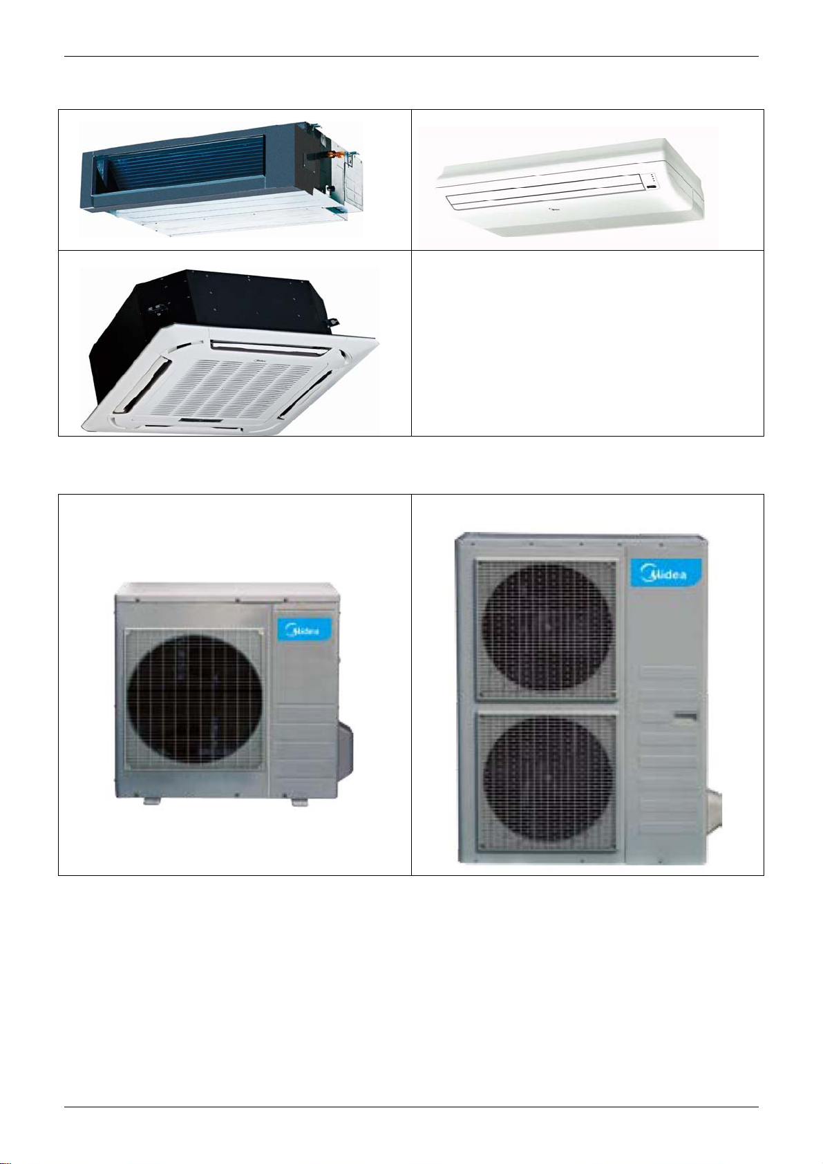
2.1 Indoor Units
Duct
Ceiling & Floor
Four-way Cassette
2.2 Outdoor Units
MOUB-36HDN1-R
MOUB-36HDN1-Q,
MOU-48HDN1, MOUB-48HDN1-R
General Information 3
Page 8
Nomenclature MLCAC-UTSM-2010-10
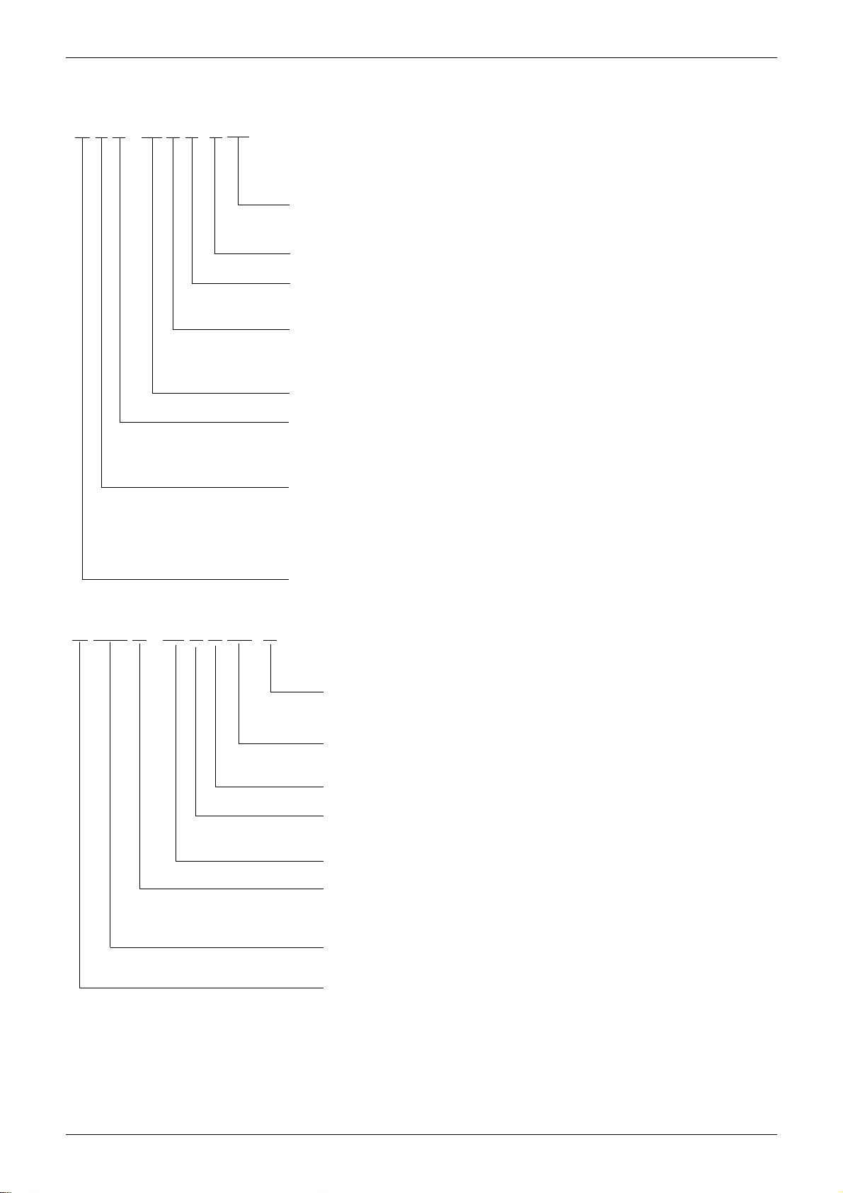
Nomenclature
1.1 Indoor Unit
M U B - 18 H R D N1
Refrigerant Type
N1 R410A
DC Inverter
Control Mode
R Remote Control
Function Code
C cooling Only
H cooling & Heating
Capacity (¡ Á1000Btu/h)
Product Series
A First Time Design B Second Time Design
C Third Time Design
3.2 Outdoor Unit
M O U D - 60 H D N1- R
Product Category
C Cassette Type
T Duct Type
U Ceiling & Floor Type
H High Static Pressure Duct Type
Midea
Power Supply
R 380~415V, 3N, 50Hz
-- 220~240V, 1N, 50Hz
Refrigerant
N1 R410A
DC Inverter
Function Code
C cooling only H cooling & heating
Capacity (¡ Á1000Btu/h)
Product Series
A Time A Designed B Time B Designed
C Time C Designed D
F Console Type
Time D Designed
Universal Outdoor Unit
O Outdoor unit U Universal
Midea
4 General Information
Page 9
MLCAC-UTSM-2010-10 Features
Features
4.1 Universal outdoor unit design
Indoor unit with the same capacity can match with the same outdoor unit.
4.2 High efficiency and energy saving.
Thanks to the DC inverter technology and optimized piping system, the EER and COP of whole
series can easily reach A-class.
4.3 Low noise and low starting current.
Thanks to the DC inverter technology, the system can work with low noise, and very small starting
current.
4.4 Intelligent refrigerant adjustment technology.
Throttle part is made up of capillary and electronic expansion valve (EXV). The outdoor unit can
output the most accurate capacity in any condition.
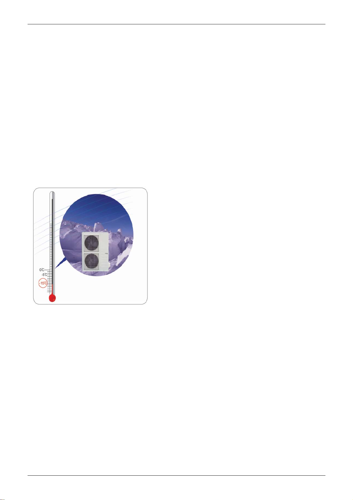
4.5 Working in cooling mode under -15℃.
Outdoor unit built-in with low ambient kit, it can control the outdoor unit’s fan and cooling can be
performed throughout the year for computer rooms, banquet halls, etc. Wide operation range
covers outdoor temperatures as low as -15℃ for cooling.
4.6 Indoor & outdoor unit’s power supply is separate.
4.7 All indoor units have network control function.
4.8 All indoor units have Auto-restart function.
General Information 5
Page 10

Indoor Units MLCAC-UTSM-2010-06
Part 2
Indoor Units
Four-way Cassette Type ....................................................... 7
Duct Type ............................................................................. 20
Ceiling & Floor Type ........................................................... 31
6 Indoor Units
Page 11

MLCAC-UTSM-2010-10 Four-way Cassette Type
Four-way Cassette Type
1. Features ........................................................................... 8
2. Dimensions .................................................................... 11
3. Service Space ................................................................ 12
4. Wiring Diagrams ........................................................... 13
5. Air Velocity and Temperature Distributions ............... 14
6. Electric Characteristics ................................................ 15
7. Sound Levels ................................................................ 15
8. Accessories ................................................................... 16
9. The Specification of Power .......................................... 17
10. Field Wiring ................................................................... 18
Four-way Cassette Type 7
Page 12
Features MLCAC-UTSM-2010-10
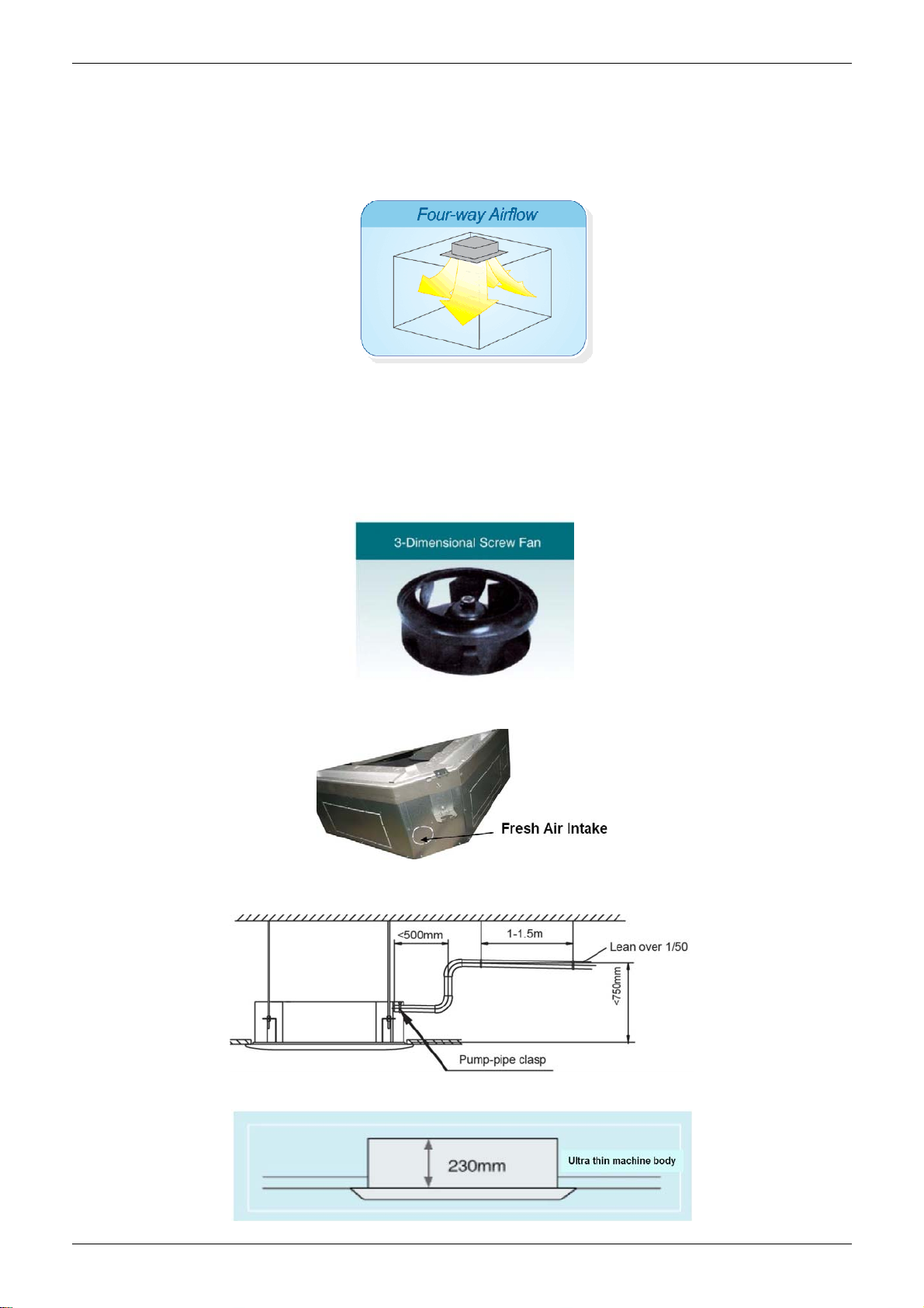
1. Features
(1) Low operation noise
—Streamline plate ensures quietness
—Creates natural and comfortable environment
(2) Efficient cooling——Equal, fast and wide range cooling
(3) Excellent performance. The optimal evaporator & sufficient airflow volume guarantees the excellent
capacity
(4) The adoption of the most advanced 3- Dimensional Screw fan
—Reduces the air resistance passing through
—Smoothes the air flow
—Makes air speed distribution to the heat exchange uniform
(5) Fresh air makes life healthier and more comfortable.
(6) Drainage pump can take up the condenser water to 750mm.
(7) Ultra thin machine body to easy installation and maintenance. 18K~24K:230mm, 36~48K:300mm.
8 Four-way Cassette Type
Page 13
MLCAC-UTSM-2010-10 Features
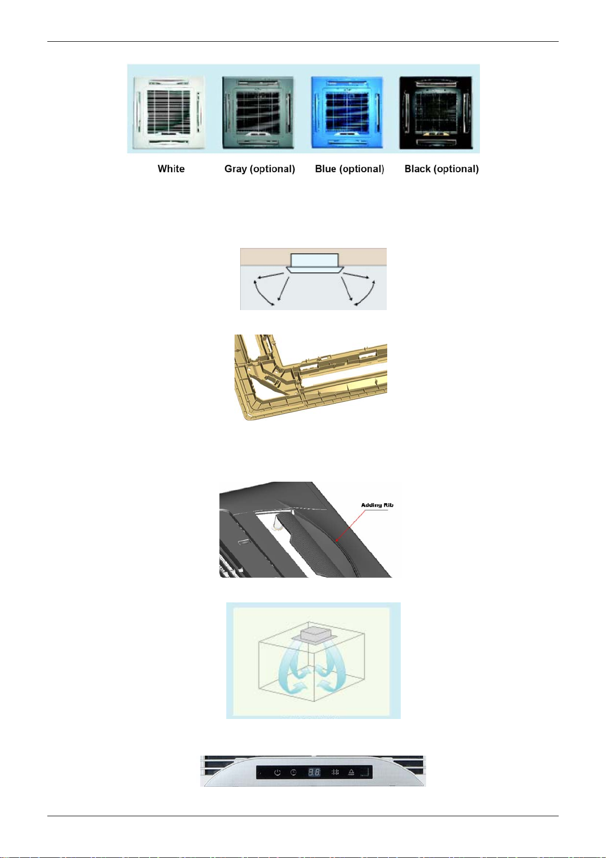
(8) Different color panels for choose: White、Gray、Blue、Black
(9) Swing angle of louver
1) Add one more swing motor, one motor driving two louvers. Controlling the interspace of each part,
minimizing the angle loss.
2) The swing angle of the first louver are 40~42 degrees and the second louver are 37~38 degrees.
New evaporator and inner configuration designed can acquire high heat-exchanger effect.
(10) More strengthening rib design around the panel, preventing the distortion for the panel.
(11) New outlet frame design to make the phenomena of coagulation great improvement: prevent the
condensing water from damaging the air guide strip.
(12) Adding rib on the panel of fan outlet, which can avoid the air outlet direct flow to people.
(13) 4 speeds available, optional super high fan speed design suitable for the large building over 3m high.
(14) Adding digital tube displaying on the display board. LED can display the Error Code to make the
malfunction checking easier.
Four-way Cassette Type 9
Page 14
Features MLCAC-UTSM-2010-10
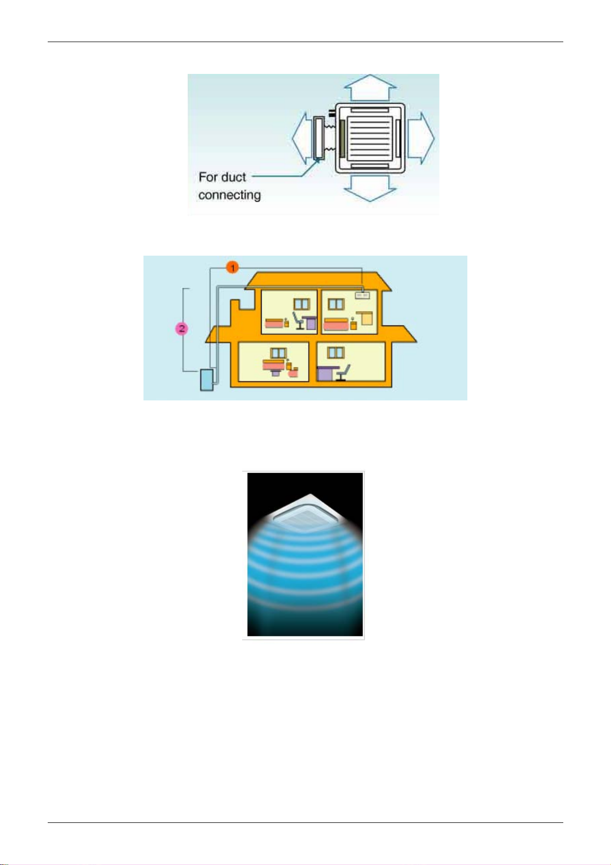
(15) Reserve spaces for air side-outlet, it is available to connect duct pipe hence air supplying from the four
sides to nearby small room..
(16) The connecting pipe and drop height is higher. Max. pipe length up to 50m(refer to ①), and Max. drop
height up to 30m(refer to ②).
(17) Optimal design, smaller Control Box, Space saving and convenient for wiring,
Using fire resistance galvanized steel for E-box material. Metal box make the control part more stable and
prevent damaging.
(18) 360°air flow panel : 360°air flow delivery ensures uniform airflow distribution(optional)
10 Four-way Cassette Type
Page 15
MLCAC-UTSM-2010-10 Dimensions
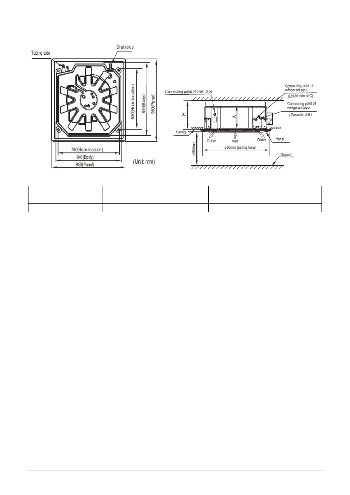
2. Dimensions
Unit: mm
MODEL(Btu/h) A B C H
36000 300 Ф15.9 Ф9.5 >330
48000 300 Ф15.9 Ф9.5 >330
Four-way Cassette Type 11
Page 16
Service Space MLCAC-UTSM-2010-10
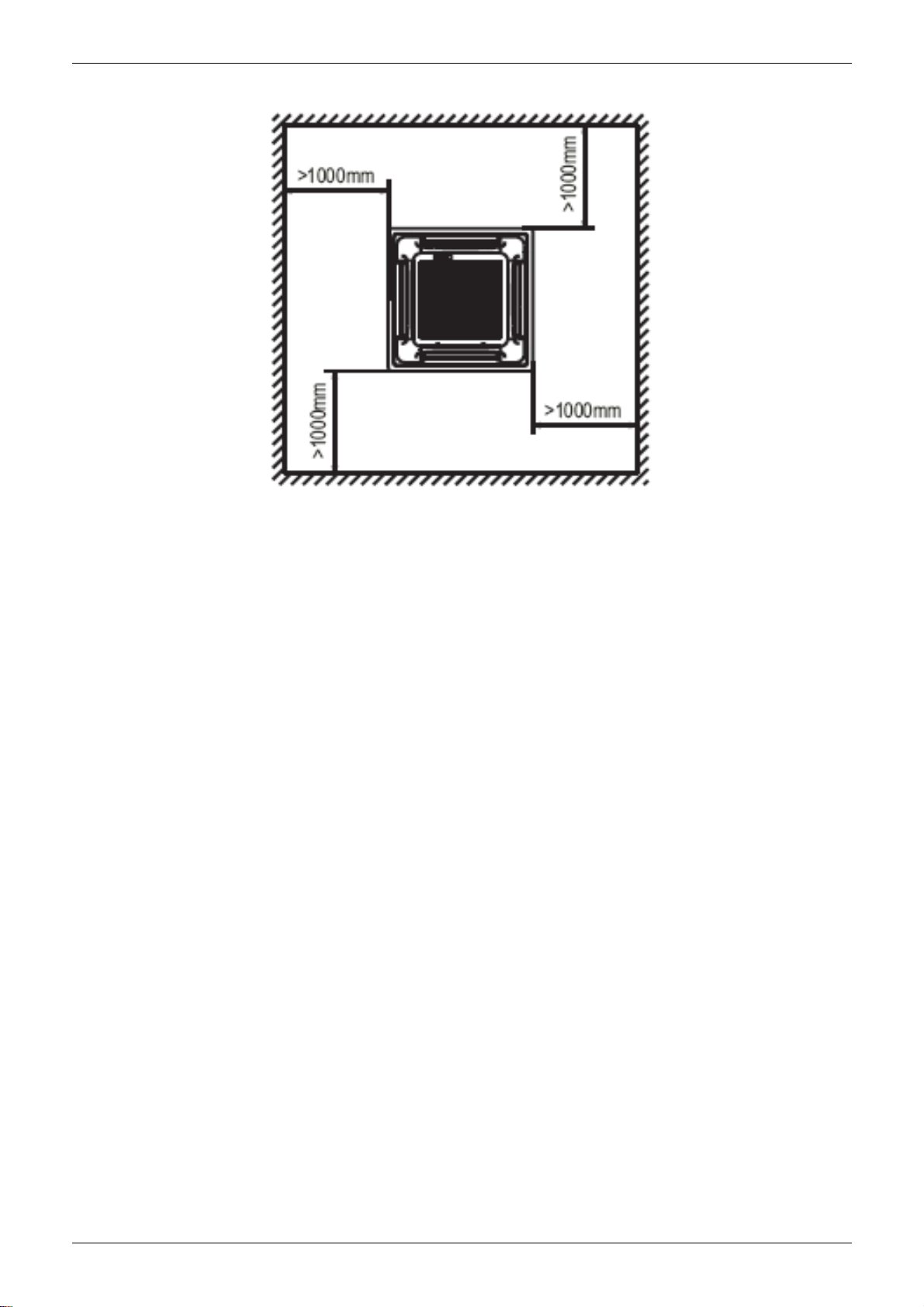
3. Service Space
12 Four-way Cassette Type
Page 17
MLCAC-UTSM-2010-10 Wiring Diagrams
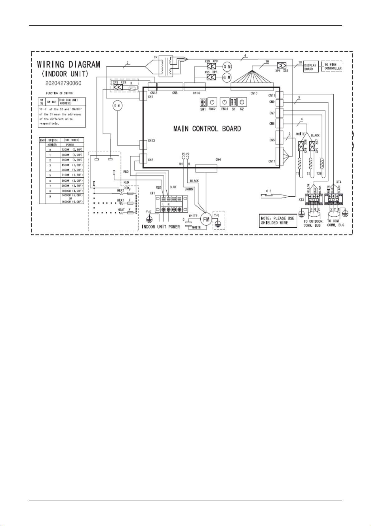
4. Wiring Diagrams
MCC-36HRDN1、MCC-48HRDN1
Four-way Cassette Type 13
Page 18
Air Velocity and Temperature Distributions MLCAC-UTSM-2010-10
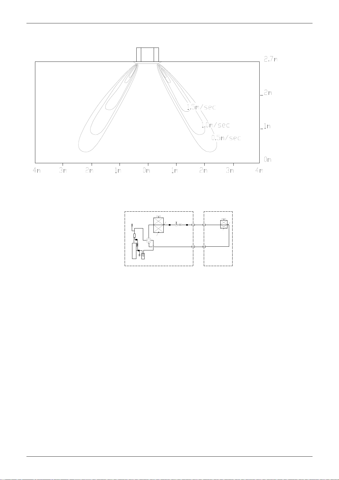
5. Air Velocity and Temperature Distributions
Airflow velocity
High pressure switch
T5
Discharge temp. sensor
Oil s epar ator
Filter
Compressor
Low pressure
Condenser
Ambient temp. sensor
4-way valve
Oil return
Capillary
Filter
Low pressure l iqui d
accumulator
switch
Condenser temp. sensor
T3
Filter
T4
Outdoor unit
Electronic
expansion valve
Capillary
Filter
Evaporator
Evaporator temp. se nsor
Room temp. sensor
Indoor uni t
T2
T1
14 Four-way Cassette Type
Page 19

MLCAC-UTSM-2010-10 Electric Characteristics
6. Electric Characteristics
Power
Supply
Model
MCC-36HRDN1 50 220-240 198 254 15
MCC-48HRDN1 50 220-240 198 254 15
Remark:
MFA: Max. Fuse Amps. (A)
Indoor Unit
Hz Voltage Min Max MFA
7. Sound Levels
Model
MCC-36HRDN1 44 42 41
MCC-48HRDN1 44 42 41
H M L
Noise level dB(A)
Four-way Cassette Type 15
Page 20
Accessories MLCAC-UTSM-2010-10
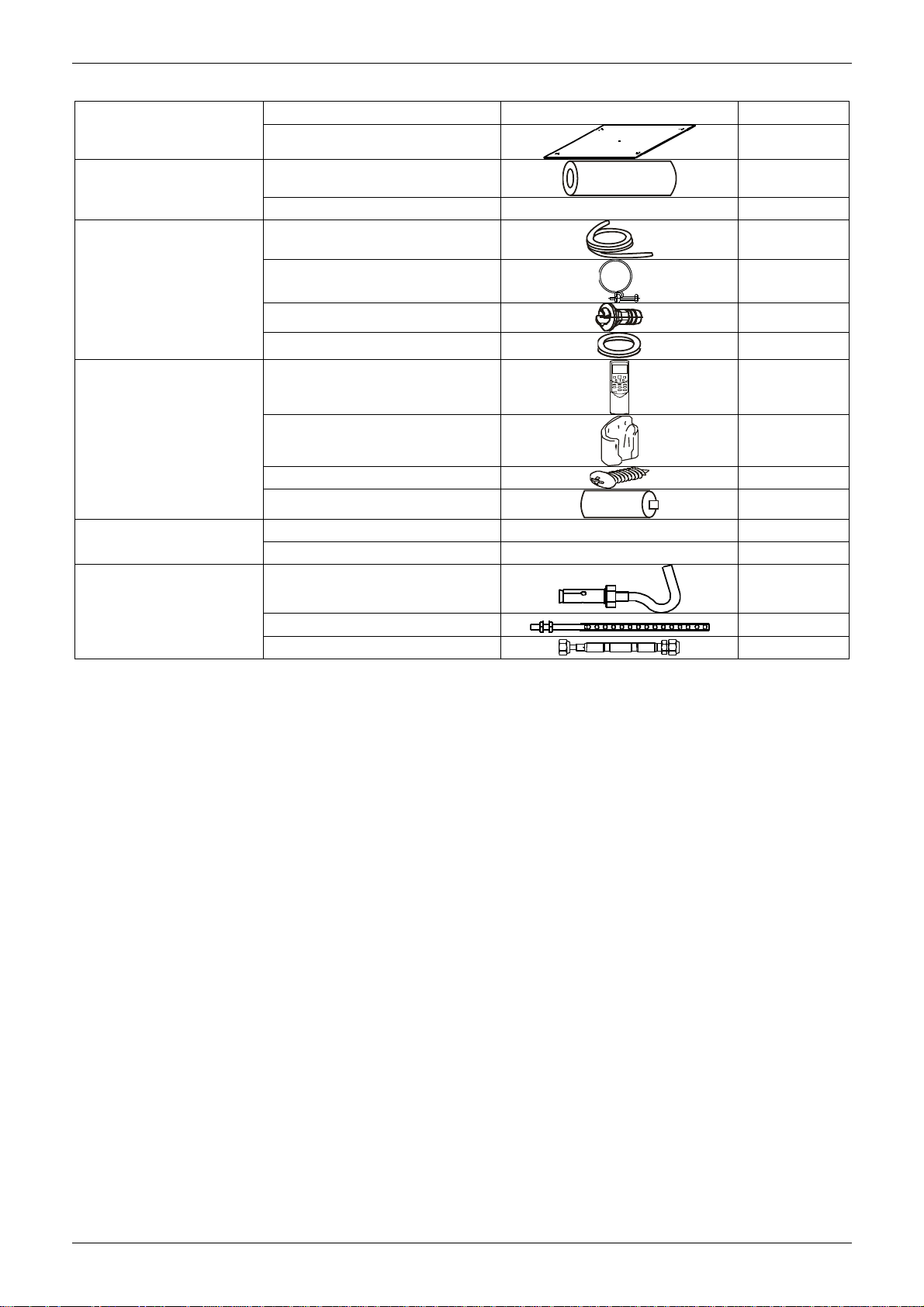
8. Accessories
Name Shape Quantity
INSTALLATION FITTINGS
Tubing & Fittings
Installation paper board
Soundproof / insulation sheath
Connecting pipe group 1
1
2
Drainpipe Fittings
Remote controller & Its
Frame
Others
Installation accessory
(The product you have
might not be provided the
following accessories
Out-let pipe sheath
Out-let pipe clasp 1
Drain joint 1
Seal ring 1
Remote controller & Its Frame
Remote controller holder 1
Mounting screw(ST2.9×10-C-H) 2
Alkaline dry batteries (AM4)
Owner's manual 1
Installation manual 1
Expansible hook
Installation hook
Orifice
1
1
2
4
4
1
16 Four-way Cassette Type
Page 21
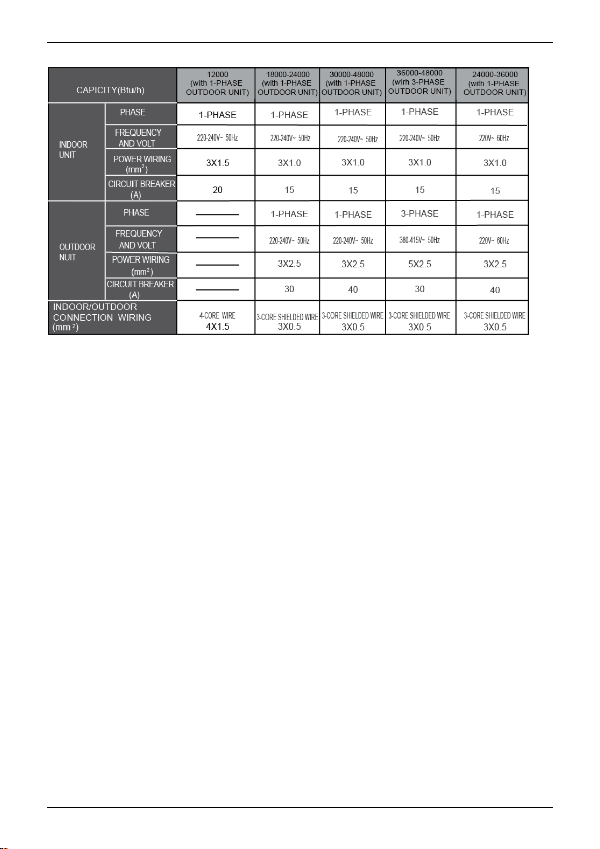
MLCAC-UTSM-2010-10 The Specification of Power
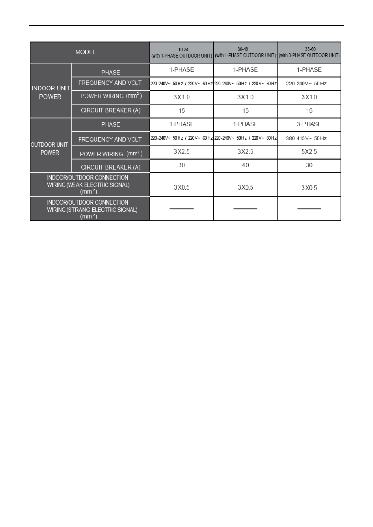
9. The Specification of Power
Four-way Cassette Type 17
Page 22
Field Wiring MLCAC-UTSM-2010-10
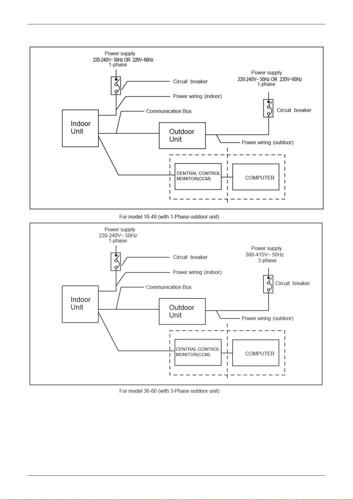
10. Field Wiring
Wiring chart
18 Four-way Cassette Type
Page 23
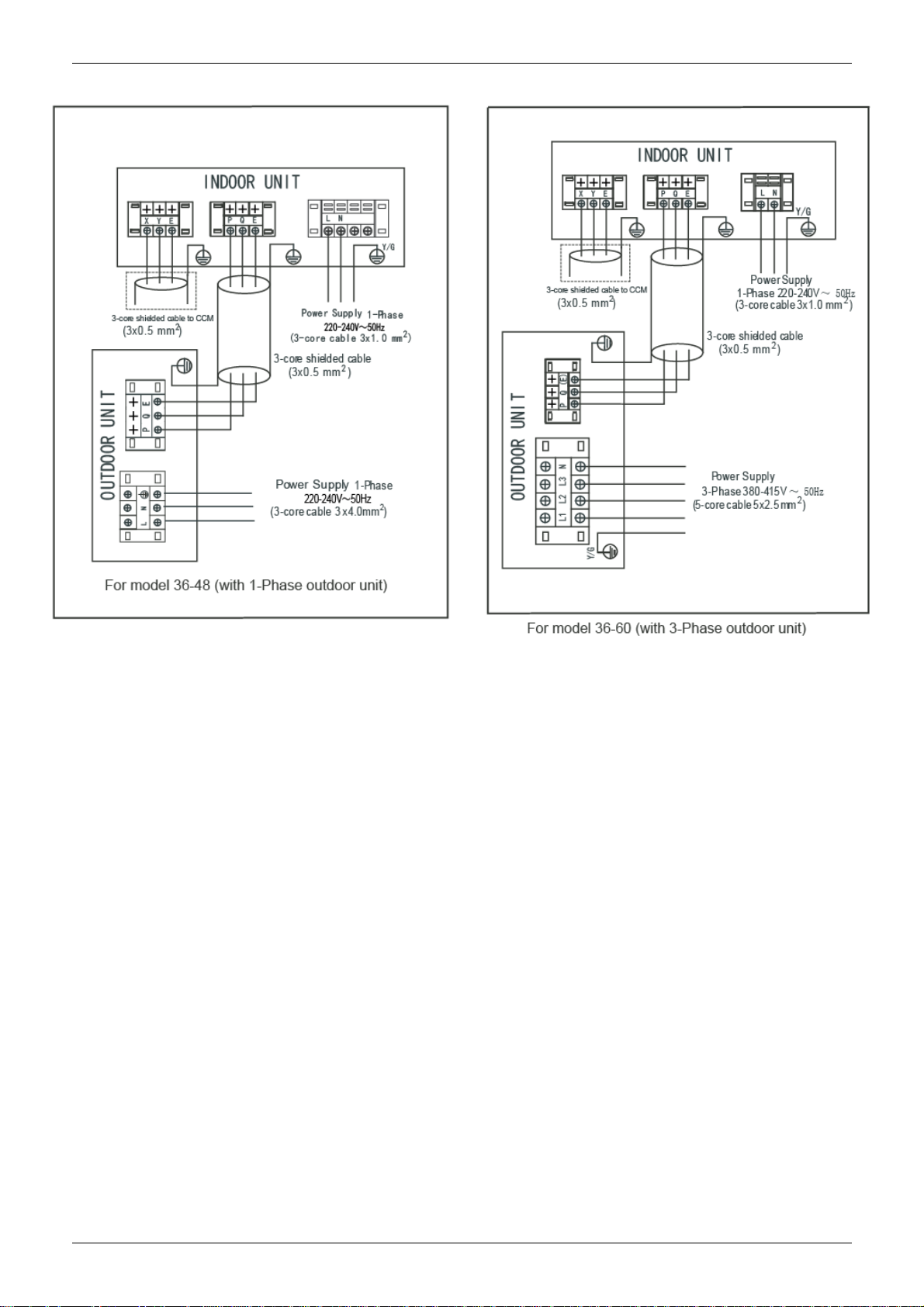
MLCAC-UTSM-2010-10 Field Wiring
Four-way Cassette Type 19
Page 24

Duct Type MLCAC-UTSM-2010-10
Duct Type
1. Features ......................................................................... 21
2. Dimensions .................................................................... 22
3. Service Space ................................................................ 23
4. Wiring Diagrams ........................................................... 24
5. Static Pressure .............................................................. 25
6. Electric Characteristics ................................................ 25
7. Sound Levels ................................................................ 26
8. Accessories ................................................................... 27
9. The Specification of Power .......................................... 28
10. Field Wiring ................................................................... 29
20 Duct Type
Page 25
MLCAC-UTSM-2010-10 Features
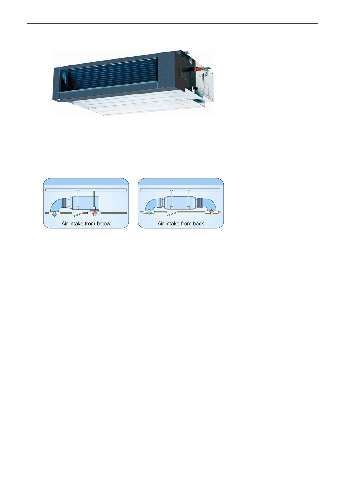
1. Features
● New structure design.
● Built-in drainage pump (Optical).
● Two air intake ways: from below or rear (standard).
● Wire controller is standard.
● Three speeds indoor unit.
● Fresh air inlet hole is reserved.
Duct Type 21
Page 26
Dimensions MLCAC-UTSM-2010-10
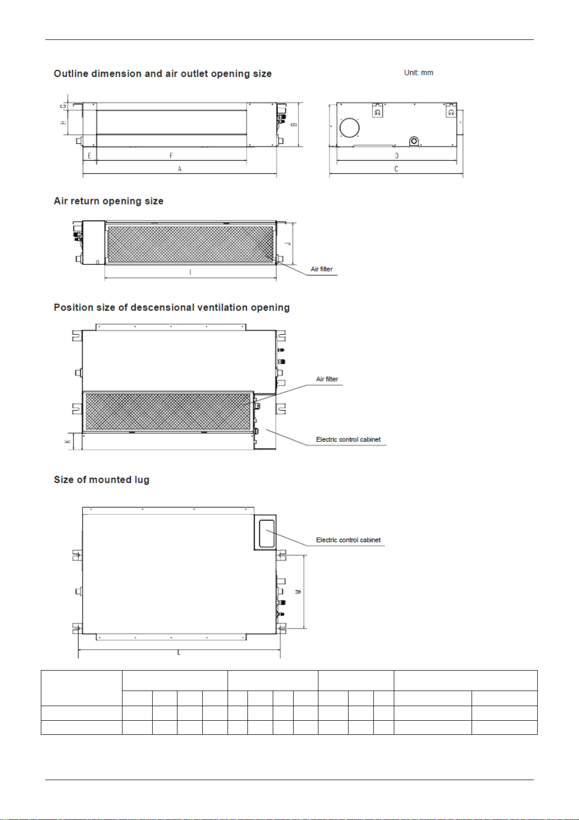
2. Dimensions
Capacity
(KBtu)
MTB-36HWDN1 1140 270 775 710 65 933 35 179 1035 260 20 1180 490
MTB-48HWDN1 1200 300 865 800 80 968 40 204 1094 288 45 1240 500
22 Duct Type
Outline
dimension(mm)
A B C D E F G H I J K L M
Air outlet o
pening size
Air return
opening size
Size of outline dimension mounted
plug
Page 27
MLCAC-UTSM-2010-10 Service Space
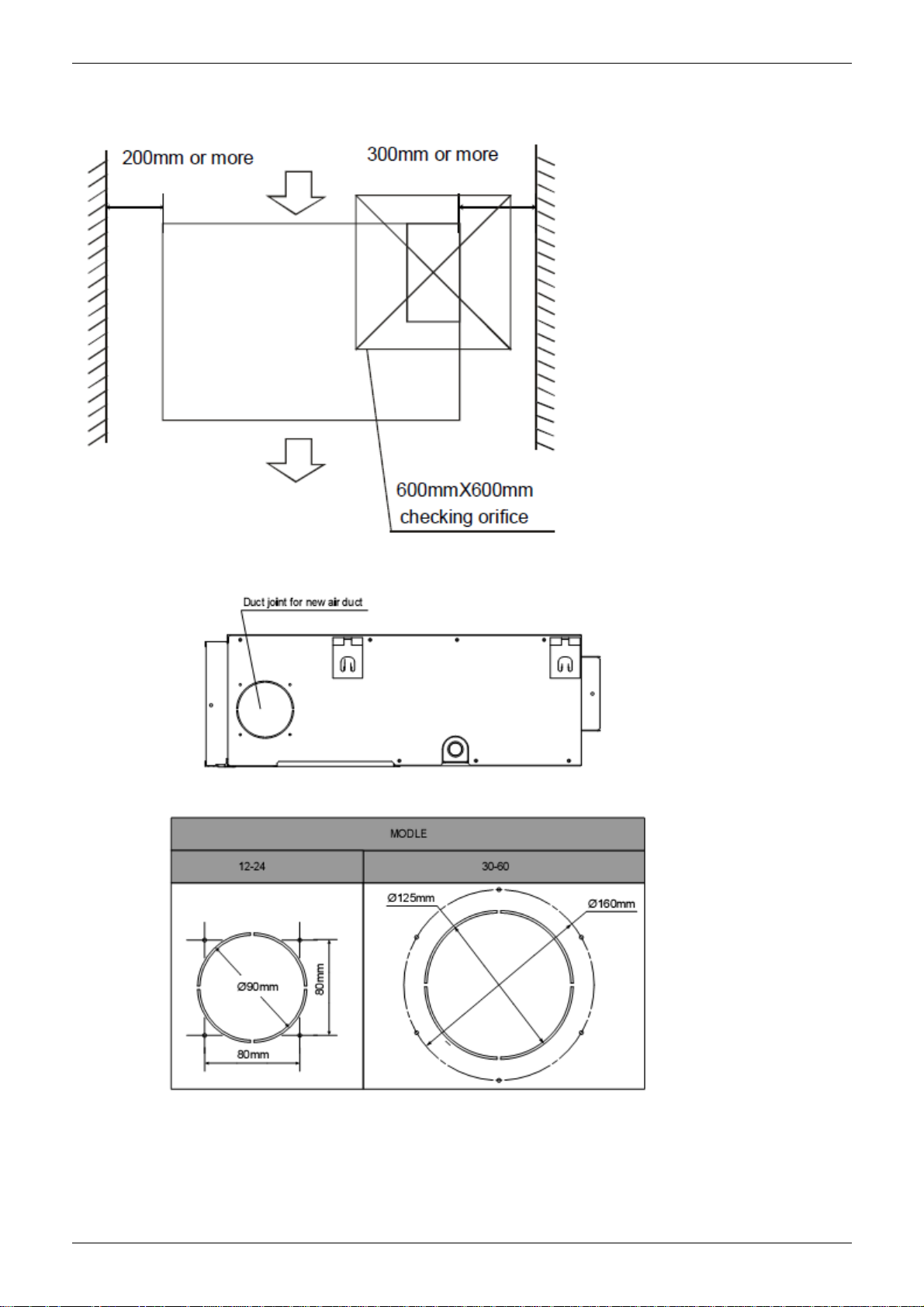
3. Service Space
Ensure enough space required for installation and maintenance.
All the indoor units reserve the hole to joint the fresh air pipe. The hole size as following:
Duct Type 23
Page 28
Wiring Diagrams MLCAC-UTSM-2010-10
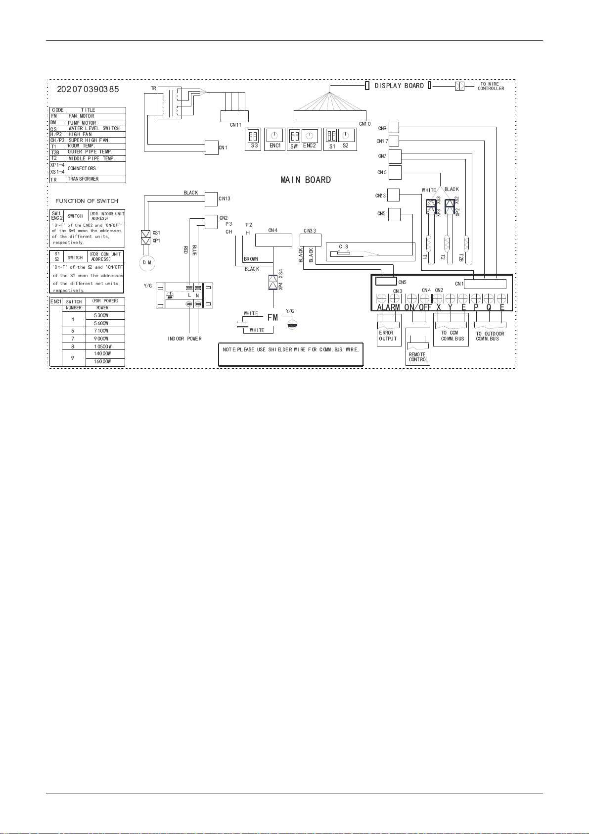
4. Wiring Diagrams
MTB-36HWDN1 MTB-48HWDN1
D M
Y/G
TR
XS1
XP1
BLAC K
BLUE
RED
L
IND OOR POWE R
CN 11
CN 1
C N13
CN2
P3
P2
CH
H
BR OWN
BLAC K
N
WHIT E
NOT E:PL EASE USE SHI ELDE R WI RE F OR C OMM .BUS WIR E,
202070390385
CODE
FM
DM
CS
H/P2
CH /P3
T1
T2B
T2
XP 1-4
XS 1-4
TR
ENC 2
' 0~F' o f t he E NC2 an d 'O N/ OFF '
respectively.
respectivel y.
ENC1
T ITLE
FAN MOTO R
PU MP MOTOR
WATER L EVEL SWI TCH
HIGH FAN
SUPER HI GH FAN
R OOM TEMP .
O UTER PIP E TE MP.
MIDDLE P IPE TEMP .
CON NECT ORS
TRANSFOR MER
FUNCTION OF SWITCH
SWITCH
SWITCH
SWITCH
NUMBER
4
5
7
8
9
(FOR INDOOR UNIT
ADDRESS)
(FOR CCM UNIT
ADDRESS)
(FOR POWER)
PO W E R
5300W
5600W
7100W
9000W
10500W
140 00W
160 00W
SW 1
of t he Sw1 m ean th e add res se s
of the different units,
S1
S2
'0~F' of t he S2 and 'ON/OFF'
of the S1 mean the addresses
of the different net units,
S3
WHITE
ENC1
SW1
MAIN BOARD
CN 4
XP4 X S4
Y/G
FM
ENC2
BLA CK
DIS PLAY BOAR D
CN1 0
CN9
S2
S1
33CN
C S
BLA CK
CN1 7
CN7
CN 6
23CN
CN5
E RROR
O UTPU T
CN5
CN 3
W HITE
T1
ON/OFF
REMOTE
CONTROL
BLAC K
XP3 XS3
T2
CN2CN 4
XY
TO CCM
CO MM.BUS
XS2
XP2
T2B
CN 1
EPQ
TO OUTD OOR
COM M.BU S
TO WIRE
CONTROLLER
EALARM
24 Duct Type
Page 29
MLCAC-UTSM-2010-10 Static Pressure
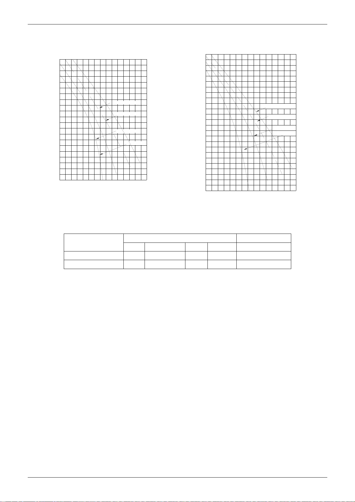
5. Static Pressure
MTB-36HWDN1 MTB-48HWDN1
Pa
90
80
70
60
50
40
External static pressure (Pa)
30
20
10
1200
1100
Super high speed
High speed
1800
Air volume(m
Mid speed
Low speed
2000
3
/h)
220016001400
2400
Pa
120
110
100
90
80
70
60
50
40
External static pressure (Pa)
30
20
10
1000
1300
19001600
Air vo lume(m
Super high speed
High speed
Mid speed
Low speed
2500
2200
3
/h)
2800
3100
6. Electric Characteristics
Model
MTB-36HWDN1 50 220-240 207 253 15
MTB-48HWDN1 50 220-240 207 253 15
Remark:
MFA: Max. Fuse Amps. (A)
Hz Voltage Min. Max. MFA
Indoor Unit Power Supply
Duct Type 25
Page 30

Sound Levels MLCAC-UTSM-2010-10
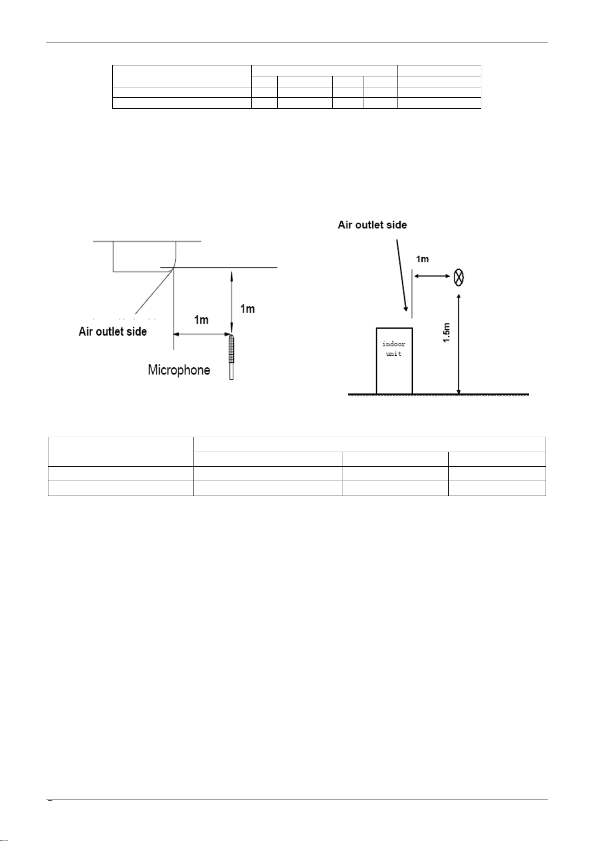
7. Sound Levels
Concealed Duct Type
Discharge
Suction
DuctDuct
1.4m
Microphone
Model
MTB-36HWDN1 46 44 42
MTB-48HWDN1 47 45 43
H M L
Noise level dB(A)
26 Duct Type
Page 31

MLCAC-UTSM-2010-10 Accessories
8. Accessories
Name Shape Quantity
Tubing & Fittings
Drainpipe Fittings
(for cooling & heating)
Remote controller & Its Frame
Soundproof / insulation sheath
Binding tape
Seal sponge
Drain joint
Seal ring
Remote controller
Frame
Mounting screw(ST2.9 10-C-H)
Alkaline dry batteries (AM4)
Remote controller manual
2
1
1
1
1
1
1
2
2
1
Wired controller & Its Frame
Others
EMS & It’s fitting
Wired controller
Owner,s manual
Installation manual
Magnetic ring (twist the electric wires L
and N around it to five circles)
1
1
1
1
Duct Type 27
Page 32

The Specification of Power MLCAC-UTSM-2010-10
9. The Specification of Power
28 Duct Type
Page 33

MLCAC-UTSM-2010-10 Field Wiring
10. Field Wiring
Duct Type 29
Page 34

Field Wiring MLCAC-UTSM-2010-10
Air-conditioner link-circuit.
30 Duct Type
Page 35

MLCAC-UTSM-2010-10 Ceiling & Floor Type
Ceiling & Floor Type
1. Features ........................................................................... 32
2. Dimensions ...................................................................... 56
3. Service Space .................................................................. 58
4. Wiring Diagrams ............................................................. 59
5. Air Velocity and Temperature Distributions ................. 60
6. Electric Characteristics .................................................. 62
7. Sound Levels ................................................................... 62
8. Accessories ..................................................................... 63
9. The Specification of Power ............................................ 64
10. Field Wiring ................................................................... 65
Ceiling & Floor Type 31
Page 36

Features MLCAC-UTSM-2010-10
1. Features
1.1. New design, more modern and elegant appearance.
1.2. Convenient installation
--The ceiling type can be easily installed into a
corner of the ceiling even if the ceiling is very narrow
--It is especially useful when installation of an air conditioner in the center of the ceiling is impossible
due to a structure such as one lighting.
1.3. Two direction auto swing (vertical & horizontal) and wide angle air flow,
--Air flow directional control minimizes the air resistance and produces wilder air flow to vertical
direction.
--The range of horizontal air discharge is widened which secures wider air flow distribution to provide
more comfortable air circulation no matter where the unit is set up
1.4. Three level fan speed, more humanism design, meets different air-supply requirement.
1.5. Water proof by utilizing the absorbing plastic film on water collector
1.6. Easy operation. Auto-restart function, remote control and optional wire control method.
1.7. Low noise level plus compact size
--Shape of the blades has been improved to prevent noise caused by turbulence.
32 Ceiling & Floor Type
Page 37

Page 38

Dimensions MLCAC-UTSM-2010-10
2. Dimensions
a. Wall mounting installation
b. Ceiling installation
56 Ceiling & Floor Type
Page 39

MLCAC-UTSM-2010-10 Dimensions
Capacity(Btu/h) A B C D E F G H
MUB-36HRDN1 1280 660 206 795 506 1195 200 203
MUB-48HRDN1 1670 680 244 1070 450 1542 200 240
Ceiling & Floor Type 57
Page 40

Service Space MLCAC-UTSM-2010-10
3. Service Space
58 Ceiling & Floor Type
Page 41

MLCAC-UTSM-2010-10 Wiring Diagrams
4. Wiring Diagrams
MUB-36HRDN1、MUB-48HRDN1
Ceiling & Floor Type 59
Page 42

Air Velocity and Temperature Distributions MLCAC-UTSM-2010-10
5. Air Velocity and Temperature Distributions
Discharge angle 60° (CEILING)
Airflow velocity
High pressure switch
T5
Discharge temp. sensor
Filter
Compressor
Oil separator
Oil return
Capillary
Filter
Low pressure
switch
4-way valve
Low pressure liquid
accumulator
Condenser
Condenser temp. sensor
T4
Ambient temp. sensor
Outdoor unit
Electronic
expansion valve
T3
Capillary
FilterFilter
Evaporator
Evaporator temp. sensor
Room temp. sensor
Indoor unit
T2
T1
60 Ceiling & Floor Type
Page 43

MLCAC-UTSM-2010-10 Air Velocity and Temperature Distributions
Discharge angle 60°(FLOOR)
Airflow velocity
Temperature
Ceiling & Floor Type 61
Page 44
Electric Characteristics MLCAC-UTSM-2010-10
V
6. Electric Characteristics
Indoor Unit Power Supply
oltage Min Max MFA
MUB-36HRDN1 50 220~240 198 254 15
MUB-48HRDN1 50 220~240 198 254 15
Remark:
MFA: Max. Fuse Amps. (A)
Model
Hz
7. Sound Levels
Ceiling Floor
Model
MUB-36HRDN1 45 43 40
MUB-48HRDN1 47 46 44
H M L
Noise level dB(A)
62 Ceiling & Floor Type
Page 45

MLCAC-UTSM-2010-10 Accessories
8. Accessories
Name Shape Quantity
Installation fittings
Remote controller & Its
holder
Others
1.Hook 2
2.Hanging arm
3. Remote controller
4. Remote controller holder 1
5. Mounting screw (ST2.9×10-C-H) 2
6. Alkaline dry batteries (AM4) 2
7. Owner's manual
8. Installation manual
9. Remote controller manual
2
1
1
1
1
Ceiling & Floor Type 63
Page 46
The Specification of Power MLCAC-UTSM-2010-10
9. The Specification of Power
64 Ceiling & Floor Type
Page 47

MLCAC-UTSM-2010-10 Field Wiring
10. Field Wiring
Ceiling & Floor Type 65
Page 48

Field Wiring MLCAC-UTSM-2010-10
66 Ceiling & Floor Type
Page 49

MLCAC-UTSM-2010-10 Outdoor Unit
Part 3
Outdoor Units
1. Dimensions ...................................................................... 68
2. Service Space .................................................................. 69
3. Piping Diagrams.............................................................. 70
4. Wiring Diagrams ............................................................. 71
5. Electric Characteristics .................................................. 73
6. Operation Limits ............................................................. 74
7. Sound Levels ................................................................... 75
8. Troubleshooting .............................................................. 76
Outdoor Unit 67
Page 50

Dimensions MLCAC-UTSM-2010-10
1. Dimensions
Unit: mm
MODEL A B C D E F H
MOUB-36HDN1-Q 940 600 376 400 340 360 1245
MOUB-36HDN1-R 990 624 366 396 340 354 966
MOU-48HDN1 940 600 376 400 340 360 1245
MOUB-48HDN1-R 940 600 376 400 340 360 1245
68 Outdoor Units
Page 51

MLCAC-UTSM-2010-10 Service Space
2. Service Space
Outdoor Units 69
Page 52

Piping Diagrams MLCAC-UTSM-2010-10
3. Piping Diagrams
MOUB-36HDN1-Q、MOU-48HDN1、MOUB-36HDN1-R、MOUB-48HDN1-R
High pressure switch
T5
Discharge temp. sensor
Oil separator
Filter
Filter
Compressor
Low pressure
switch
Oil return
Capillary
Condenser
Ambient temp. sensor
4-way valve
Low pressure liquid
accumulator
Condenser temp. sensor
T3
Filter
T4
Outdoor unit
Electronic
expansion valve
Capillary
Filter
Evaporator
Evaporator temp. sensor
Room temp. sensor
Indoor unit
T2
T1
70 Outdoor Units
Page 53

MLCAC-UTSM-2010-10 Wiring Diagrams
4. Wiring Diagrams
MOUB-36HDN1-Q MOU-48HDN1
MOUB-36HDN1-R
Outdoor Units 71
Page 54

Wiring Diagrams MLCAC-UTSM-2010-10
MOUB-48HDN1-R
72 Outdoor Units
Page 55

MLCAC-UTSM-2010-10 Electric Characteristics
5. Electric Characteristics
Model
MOUB-36HDN1-Q 50 220-240 198 254 40
MOUB-36HDN1-R 50 380-415 342 440 40
MOU-48HDN1 50 220-240 198 254 40
MOUB-48HDN1-R 50 380-415 342 440 40
Remark:
MFA: Max. Fuse Amps. (A)
Hz Voltage Min. Max. MFA
Outdoor Unit Power Supply
Outdoor Units 73
Page 56

Operation Limits MLCAC-UTSM-2010-10
6. Operation Limits
Heating
25
24
20
15
10
5
0
-5
Outdoor temperature(℃ WB)
-10
-15
STD
15
10
17
20
Indoor temperature(℃ DB)
25
30
35
74 Outdoor Units
Page 57

MLCAC-UTSM-2010-10 Sound Levels
7. Sound Levels
Model
MOUB-36HDN1-Q 57/52
MOUB-36HDN1-R 55/50
MOU-48HDN1 59/54
MOUB-48HDN1-R 59/54
Noise level dB(A)
H/L
Outdoor Units 75
Page 58

Troubleshooting MLCAC-UTSM-2010-10
8. Troubleshooting
8.1 Indoor unit malfunction
8.1.1 Display board
Ceiling & Floor Normal 4-way cassette
Duct
76 Outdoor Units
Page 59

MLCAC-UTSM-2010-10 Troubleshooting
8.1.2 Troubleshooting
For Normal 4-way cassette
For ceiling & floor
Outdoor Units 77
Page 60

Troubleshooting MLCAC-UTSM-2010-10
For Duct type
78 Outdoor Units
Page 61

MLCAC-UTSM-2010-10 Troubleshooting
1. Operation lamp flashes
Operation lamp flashes at 5Hz
Judge 1: Indoor temp. sensor is abnormal
Check whether the resistance of the evaporator temp. sensor is
correct according to Annex 1
No
Replace evaporator temp. sensor
Yes
Judge 2: Room temp. sensor is abnormal
Check whether the resistance of the room temp.
sensor is correct according to Annex 1
No
Replace room temp. sensor
Yes
Replace indoor PCB
Outdoor Units 79
Page 62

Troubleshooting MLCAC-UTSM-2010-10
2. Timer lamp flashes
Timer lamp flashes at 5Hz
Judge: Indoor/outdoor unit communication is abnormal
Refer to the outdoor unit LED display E2 malfunction in the following part
3. Alarm lamp slow-flash
Indoor alarm lamps flash at 1Hz
Condenser temp. sensor or outdoor unit is malfunction
Judge 1: Condenser temp. sensor is abnormal
Check whether the resistance of the condenser temp. sensor is
correct according to Annex 1
No
Replace condenser temp. sensor
Yes
Judge 2: Outdoor unit is abnormal
Refer to the outdoor unit LED display E4、P1、P2 malfunction in the
following part
80 Outdoor Units
Page 63

MLCAC-UTSM-2010-10 Troubleshooting
3. Alarm lamp quick-flash
Alarm lamp flashes at 5Hz
Judge: Water level switch is abnormal.
Check whether the water pump can work normally
No
Replace water pump
Yes
Select the cooling mode to make water pump work for a few minutes, then check
whether the system can run normally
Yes
Trouble is solved
Check whether the water drain pipe is blocked
No
Yes
Solve to make the water can flow
fluently
No
Replace indoor PCB
4. Defrost lamp flashes
Defrost lamp flashes
Judge: Mode conflicts malfunction
Turn the indoor unit to heating mode or turn off the unit
Outdoor Units 81
Page 64

Troubleshooting MLCAC-UTSM-2010-10
9.2 Outdoor unit malfunction
Display Malfunction or Protection
E0 EEPROM malfunction
E2 Communication malfunction between indoor IC and outdoor IC
E3 Communication malfunction in outdoor IC and DSP
E4 Malfunction of outdoor temperature sensor
E5 Voltage protection of compressor
E6 PFC module protection (Only for 30K, 36K & 48K with 1 phase)
P0 Top temperature protection of compressor
P1 High pressure protection
P2 Low pressure protection
P3 Current protection of compressor
P4 Discharge temperature protection of compressor
P5 High temperature protection of condenser
P6 Module protection
1. E0 malfunction
Judge: Check whether the EEPROM is inserted well
E0 display
EEPROM malfunction
Yes
Replace outdoor main board
No
Insert the EEPROM well
82 Outdoor Units
Page 65

MLCAC-UTSM-2010-10 Troubleshooting
2. E2 malfunction
E2 display
Communication malfunction between indoor IC and outdoor IC
Judge 1: Check whether the indoor unit power is on
No
Turn on the indoor unit power
Yes
Judge 2: Check whether the signal wiring is shield cable or whether
the shield cable is earthed
No
Adopt the shield cable/ let shield cable earthed
Judge 3: Check whether the signal wiring between the indoor and
outdoor units is wrong polarity?
Yes
No
Yes
Connect the signal wiring correctly
Judge 4: Check whether the signal wiring between the indoor and
outdoor units is broken?
Yes
Replace the broken wiring
No
Indoor or outdoor main board is broken. Replace the main
board until the malfunction disappears.
Outdoor Units 83
Page 66

Troubleshooting MLCAC-UTSM-2010-10
3. E3 malfunction (For 18K & 24K & 30K)
E3 display
Communication malfunction in outdoor IC and DSP
Check whether the indicator lights LED1 on the main board is flashing
Yes
Replace the outdoor main board
No
Check whether the connecting wiring between the IPM module and the CN4
on the main board is broken off
Yes
Insert the connecting wiring well over
again
No
Disconnect the connecting wiring between the IPM module and the CN4 on the
main board, use the multimeter to measure the voltage between the IPM module
CN1 port’s 3 and 4 pillar, check whether it is 5V, (the third pillar on the main board
labels +5V)
Yes
Replace outdoor main board
No
Check whether the connecting wiring between the IPM module positive
pole and the CN12 on the power board is broken off
Yes
Insert the connecting wiring well over again
No
Check whether the connecting wiring between the IPM module negative
pole and the CN13 on the power board is broken off
Yes
Insert the connecting wiring well over again
No
Use the multimeter to measure whether the voltage between the CN12 and
the CN13 on the power board is between +(277V~345)V
No
Replace the power board
84 Outdoor Units
Yes
Replace the IPM module
Page 67

MLCAC-UTSM-2010-10 Troubleshooting
4. E3 malfunction (For 36K & 48K & 60K)
E3 display
Communication malfunction in outdoor IC and DSP
Check whether the indicator lights LED1 or LED2 on the main control
board are flashing
Yes
Replace PCB
Install the IC-U3 chip of the PCB over again, check whether the system
can run normally
No
Yes
Trouble is solved
No
Yes
Check whether the output of the transformer to CN4 socket is well
Replace PCB
No
Replace the transformer
Outdoor Units 85
Page 68

Troubleshooting MLCAC-UTSM-2010-10
5. E4 malfunction
E4 display
Judge 1: Outdoor condenser temp. sensor (T3) is malfunction
Check whether the wiring of the condenser temp. sensor is broken off
Yes
Connect the wiring well
No
Check whether the resistance of condenser temp. sensor is wrong
refer to the Annex 1
Yes
Replace condenser temp. sensor
No
Judge 2: Outdoor ambient temp. sensor (T4) is malfunction
Check whether the wiring of the outdoor ambient temperature sensor (T4) is
broken off
Yes
Connect the wiring well
No
Check whether the resistance of outdoor ambient temperature sensor
(T4) is wrong refer to the Annex 1
Yes
Replace outdoor ambient temperature sensor
(T4)
No
Replace PCB
86 Outdoor Units
Page 69

MLCAC-UTSM-2010-10 Troubleshooting
6. E5 malfunction
E5 display
Voltage protection of compressor
Check the voltage of outdoor unit power supply, whether the voltage
between L(1) and N is about 172-265V
No
Check the power supply
Yes
Replace the power board, then check whether the system can run normally
Yes
Trouble is solved
No
Replace outdoor main board
7. E6 malfunction (Only for 30K, 36K & 48K with 1 phase)
E6 display
PFC module protection
Check whether the connecting line between main
board and the PFC module is connected tightly
No
Connect it tightly, check normal or not
Yes
No
Check whether the voltage between P
and N of IPM module is 380-390V
Yes
Replace the outdoor main board
No
Replace the PFC module
Outdoor Units 87
Page 70

Troubleshooting MLCAC-UTSM-2010-10
8. P1 malfunction
P1 display
High pressure protection
Judge 1: Whether the wiring between the high pressure switch and main
control board is connected well or correctly
No
Connect it well
Yes
Judge 2: Whether the high pressure switch is broken
Method: Short connect the high pressure switch socket, check
whether the system can run normally
Yes
Replace high pressure switch
No
Check whether the refrigerant system is ok
Judge 3: Check whether the outdoor ambient temperature is too high
Yes
Stop the unit
No
Yes
Judge 4: Check whether the outdoor unit is bad ventilation
Make the outdoor unit ventilate well
Judge 5: Check whether the heat exchanger is dirty
No
Yes
Clean the heat exchanger
No
Yes
Judge 6: Check whether the refrigerant pipe is blocked
No
Replace outdoor main board
88 Outdoor Units
Let the refrigerant out, then use the high pressure
nitrogen or refrigerant to blow pipe, vacuumize and
charge the refrigerant again
Page 71

MLCAC-UTSM-2010-10 Troubleshooting
9. P2 malfunction
P2 display
Low pressure protection
Judge 1: The wiring between the low pressure switch and main control
board is connected well or correctly
No
Connect it well
Yes
Judge 2: Whether the low pressure switch is broken
Method: Short connect the low pressure switch socket, check
whether the system can run normally
Yes
Replace low pressure switch
No
Check whether the refrigerant system is ok
Judge 3: Check whether the outdoor ambient temperature is too low
Yes
Stop the unit
No
Method: Connect the pressure gauge to the gauge joint of the system,
check whether the pressure is lower than 0.14MPa
Judge 4: The refrigerant of the system is leakage
Yes
Leak hunting: Charge nitrogen or refrigerant to
the system, if the leakage is serious, there will
be distinct gas leakage “cici” sound; if the
leakage is slight, use the suds (mixture of water
and abluent is also ok if it can make bubble) or
electronic leak detector.
No
Yes
Judge 5: The refrigerant pipe is blocked
No
Replace outdoor main board
Outdoor Units 89
Let the refrigerant out, then use the high pressure
nitrogen or refrigerant to blow pipe, vacuumize and
charge the refrigerant again
Page 72

Troubleshooting MLCAC-UTSM-2010-10
10. P3 malfunction
P3 display
Current protection of compressor
Judge 1: Check whether the input current of the power supply wire is more
than 20A (For 36K & 48K with 1 phase, it is 30A)
Yes
Check whether the refrigerant system is ok
Judge 2: Check whether the outdoor ambient temperature is too high
Yes
Stop the unit
Judge 3: Check whether the outdoor unit is bad ventilation
No
Yes
Make the outdoor unit ventilate well
Judge 4: Check whether the heat exchanger is dirty
No
Yes
Clean the heat exchanger
Judge 5: The refrigerant pipe is blocked
No
No
Yes
Let the refrigerant out, then use the high pressure
nitrogen or refrigerant to blow pipe, vacuumize and
charge the refrigerant again
Replace outdoor main board
90 Outdoor Units
Page 73

MLCAC-UTSM-2010-10 Troubleshooting
11. P4 malfunction
When compressor discharge temperature is higher than 115°C, the unit will stop, and unit runs again when
compressor discharge temperature is lower than 90°C.
P4 display
Discharge temperature protection of compressor
Check whether the compressor discharge temp. is more than 115°C ?
Yes
No
Check whether the wiring connection is right
between compressor discharge temp. sensor and
PCB according to wiring diagrams
No
Correct the wiring connection
Yes
Judge: The discharge temp. sensor is broken
Check whether the refrigerant is leak
Yes
Stop leaking and add refrigerant
Method: Check whether the resistance of compressor discharge
temp. sensor is right refer to the Annex 2
No
Replace the compressor
discharge temp. sensor
Yes
Replace outdoor main board
Outdoor Units 91
Page 74

Troubleshooting MLCAC-UTSM-2010-10
12. P5 malfunction
When condenser high temp. is more than 65°C, the unit will stop, and unit runs again when outdoor pipe
temp. less than 52°C.
P5 display
High temperature protection of condenser
Check whether the condenser temperature is more than 65°C
Yes
No
Check whether the resistance of condenser temp.
sensor is correct refer to the Annex 1
No
Replace the temperature sensor
Yes
Replace outdoor main board
Stop the unit
Yes
Judge1: The outdoor temp. is too high
Clean the heat exchanger
Yes
Judge 2: Check whether the heat exchanger is dirty
No
Let the refrigerant out, then use the high pressure
nitrogen or refrigerant to blow pipe, vacuumize and
charge the refrigerant again
Yes
Judge 3: The refrigerant pipe is blocked
No
No
Replace outdoor main board
92 Outdoor Units
Page 75

MLCAC-UTSM-2010-10 Troubleshooting
13. P6 malfunction (For single phase units)
P6 display
Module protection
Check whether the voltage range of P-N on
IPM module is normal? DC277-356V for
18K/24K/30KBtu/h; DC277-410V for
36K/48KBtu/h
No
Check whether the input power supply
is correct? 220-240V, 1N, 50Hz
No
Regulate it to correct,
then check whether the
system can work
normally?
Yes
Yes
Check whether the connecting line
between main board and the IPM
module is connected tightly
No
Connect it tightly,
check ok or not?
Check whether the power
supply line is connected
correctly and tightly
No
Connect it correctly and
tightly, check ok or not?
Yes
No
Yes
Check whether the connecting
line of the compressor is
connected correctly or tightly
Yes
Replace the IPM module, check
whether the system can work
normally?
No
Yes
Connect it well,
check ok or not?
No
Check whether the lines in
E-part box are connected tightly
Yes
Check whether the single-phase bridge is
normal? Use the multimeter to measure the
resistance between each two terminals, check
whether there is the condition that value of
resistance is 0
No
Connect it tightly,
check ok or not?
Yes
single-phase bridge
Replace the main board, check
whether the system can work
No
normally?
No
Trouble is solved
Yes
Trouble is solved
No
Check whether the connecting line
of every reactor is normal? If the
line is broken, the resistance of the
two ports is ∞
No
No
No
No
Replace the
Replace the
connecting line
Replace the compressor, check
whether the system can work
normally?
Outdoor Units 93
Yes
Trouble is solved
Yes
Check whether the fuse on
the power board is normal?
Yes
Replace the power board
No
Replace with
the same model
fuse
Page 76

Troubleshooting MLCAC-UTSM-2010-10
14. P6 malfunction (For three phases units)
P6 display
Module protection
Check whether the voltage range of P-N on
IPM module is normal? DC 350-650V
No
Check whether the input power supply
is correct? 380-415V, 3N, 50Hz
No
Regulate it to correct,
then check whether the
system can work
normally?
Yes
Yes
Check whether the connecting line
between main board and the IPM
module is connected tightly
Connect it tightly,
check ok or not?
Check whether the power
supply line is connected
correctly and tightly
No
Connect it correctly and
tightly, check ok or not?
Yes
No
Yes
Check whether the connecting
line of the compressor is
connected tightly
Connect it tightly,
check ok or not?
Check whether the lines in
E-part box are connected tightly
Yes
No
Connect it tightly,
check ok or not?
Yes
No
Trouble is solved
Check whether the three phase bridge
is normal?
Yes
No
Replace the three phase
Yes
Replace the IPM module, check
whether the system can work
normally?
No
Check whether the 3300µF/400V
electrolytic capacitor is normal?
No
Replace this electrolytic
capacitor
Replace the main board, check whether the
system can work normally?
Yes
Trouble is solved
No
Replace the compressor , check whether
the system can work normally?
Yes
Trouble is solved
No
No
No
bridge
94 Outdoor Units
Page 77

MLCAC-UTSM-2010-10 Troubleshooting
Appendix Indoor Temp. and Pipe Temp. Sensor Resistance Value Table (℃--K)
℃
-20 115.266 20 12.6431 60 2.35774 100 0.62973
-19 108.146 21 12.0561 61 2.27249 101 0.61148
-18 101.517 22 11.5000 62 2.19073 102 0.59386
-17 96.3423 23 10.9731 63 2.11241 103 0.57683
-16 89.5865 24 10.4736 64 2.03732 104 0.56038
-15 84.2190 25 10.000 65 1.96532 105 0.54448
-14 79.3110 26 9.55074 66 1.89627 106 0.52912
-13 74.5360 27 9.12445 67 1.83003 107 0.51426
-12 70.1698 28 8.71983 68 1.76647 108 0.49989
-11 66.0898 29 8.33566 69 1.70547 109 0.48600
-10 62.2756 30 7.97078 70 1.64691 110 0.47256
-9 58.7079 31 7.62411 71 1.59068 111 0.45957
-8 56.3694 32 7.29464 72 1.53668 112 0.44699
-7 52.2438 33 6.98142 73 1.48481 113 0.43482
-6 49.3161 34 6.68355 74 1.43498 114 0.42304
-5 46.5725 35 6.40021 75 1.38703 115 0.41164
-4 44.0000 36 6.13059 76 1.34105 116 0.40060
-3 41.5878 37 5.87359 77 1.29078 117 0.38991
-2 39.8239 38 5.62961 78 1.25423 118 0.37956
-1 37.1988 39 5.39689 79 1.21330 119 0.36954
0 35.2024 40 5.17519 80 1.17393 120 0.35982
1 33.3269 41 4.96392 81 1.13604 121 0.35042
2 31.5635 42 4.76253 82 1.09958 122 0.3413
3 29.9058 43 4.57050 83 1.06448 123 0.33246
4 28.3459 44 4.38736 84 1.03069 124 0.32390
5 26.8778 45 4.21263 85 0.99815 125 0.31559
6 25.4954 46 4.04589 86 0.96681 126 0.30754
7 24.1932 47 3.88673 87 0.93662 127 0.29974
8 22.5662 48 3.73476 88 0.90753 128 0.29216
9 21.8094 49 3.58962 89 0.87950 129 0.28482
10 20.7184 50 3.45097 90 0.85248 130 0.27770
11 19.6891 51 3.31847 91 0.82643 131 0.27078
12 18.7177 52 3.19183 92 0.80132 132 0.26408
13 17.8005 53 3.07075 93 0.77709 133 0.25757
14 16.9341 54 2.95896 94 0.75373 134 0.25125
15 16.1156 55 2.84421 95 0.73119 135 0.24512
16 15.3418 56 2.73823 96 0.70944 136 0.23916
17 14.6181 57 2.63682 97 0.68844 137 0.23338
18 13.9180 58 2.53973 98 0.66818 138 0.22776
19 13.2631 59 2.44677 99 0.64862 139 0.22231
K Ohm
℃
K Ohm
℃
K Ohm
℃
K Ohm
Outdoor Units 95
Page 78

Installation MLCAC-UTSM-2010-10
Part 4
Installation
1.Precaution on Installation ................................................... 97
2.Vacuum Dry and Leakage Checking ................................. 98
3.Additional Refrigerant Charge .........................................100
4.Water Drainage ................................................................101
5.Insulation Work ................................................................104
6.Wiring ...............................................................................105
7.Test Operation ..................................................................106
96 Installation
Page 79

MLCAC-UTSM-2010-10 Precaution on Installation
1. Precaution on Installation
1). Measure the necessary length of the connecting pipe, and make it by the following way.
a. Connect the indoor unit at first, then the outdoor unit.
Bend the tubing in proper way. Do not harm them.
Specially Notice the pipe length/height/dimension of each capacity.
Maximum pipe length
Model Max. Length Max. Elevation
12,000Btu/h 10m 5m
18,000Btu/h ~24,000Btu/h 25m 12m
30,000Btu/h 25m 15m
36,000Btu/h 30m 20m
48,000Btu/h~60,000Btu/h 50m 25m
Piping sizes
Model Liquid(mm) Gas(mm)
12,000Btu/h~18,000Btu/h 6.4 12.7
24,000Btu/h~60,000Btu/h
CAUTIONS
Daub the surfaces of the flare pipe and the joint nuts with frozen oil, and wrench it for 3~4 rounds
With hands before fasten the flare nuts.
Be sure to use two wrenches simultaneously when you connect or disconnect the pipes.
Pipe gauge Tightening torque
Φ6.4
Φ9.5
Φ12.7
Φ15.9
Φ19.1
b. The stop value of the outdoor unit should be closed absolutely (as original state). Every time you connect it, first loosen the nuts at the part
of stop value, then connect the flare pipe immediately (in 5 minutes). If the nuts have been loosened for a long time, dusts and other
impurities may enter the pipe system and may cause malfunction later. So please expel the air out of the pipe with refrigerant before
connection.
c. Expel the air after connecting the refrigerant pipe with the indoor unit and the outdoor unit. Then fasten the nuts at the repair-points.
2) Locate The Pipe
a. Drill a hole in the wall (suitable just for the size of the wall conduit), then set on the fittings such as the wall conduit and its cover.
b. Bind the connecting pipe and the cables together tightly with binding tapes. Do not let air in, which will cause water leakage by
condensation.
c. Pass the bound connecting pipe through the wall conduit from outside. Be careful of the pipe allocation to do no damage to the tubing.
3) Connect the pipes.
4) Then, open the stem of stop values of the outdoor unit to make the refrigerant pipe connecting the indoor unit with the outdoor unit in
fluent flow.
5) Be sure of no leakage by checking it with leak detector or soap water.
6) Cover the joint of the connecting pipe to the indoor unit with the soundproof / insulating sheath (fittings), and bind it well with the tapes to
prevent leakage.
14.2~17.2N.m
(144~176 kgf.cm)
32.7~39.9N.m
(333~407kgf.cm)
49.5~60.3N.m
(504~616kgf.cm)
61.8~75.4N.m
(630~770 kgf.cm)
97.2~118.6N.m
(990~1210kgf.cm)
9.5 15.9
Flare dimension A
Min (mm) Max
Flare shape
8.3 8.7
12.0 12.4
15.4 15.8
18.6 19.1
22.9 23.3
Installation 97
Page 80

Vacuum Dry and Leakage Checking MLCAC-UTSM-2010-10
2. Vacuum Dry and Leakage Checking
1) Vacuum Dry: use vacuum pump to change the moisture (liquid) into steam (gas) in the pipe and discharge it out of the pipe to make the
pipe dry. Under one atmospheric pressure, the boiling point of water(steam temperature) is 100. Use vacuum pump to make the
pressure in the pipe near vacuum state, the boiling point of water falls relatively. When it falls under outdoor temperature, the moisture in
the pipe will be vaporized.
Necessary
vacuum
degree
2) Vacuum dry procedure
There are two methods of vacuum dry due to different construction environment: common vacuum dry, special vacuum dry.
. Common vacuum dry procedure
Vacuum dry (for the first time)---connect the all-purpose detector to the inlet of liquid pipe and gas pipe, and run the vacuum pump more
than two hours (the vacuum pump should be below -755mmHg)
If the pump can’t achieve below -755mmHg after pumping 2 hours, moisture or leakage point will still exist in the pipe. At this time, it
should be pumped 1 hour more.
If the pump can’t achieve -755mmHg after pumping 3 hours, please check if there are some leakage points.
Vacuum placement test: place 1 hour when it achieves -755mmHg, pass if the vacuum watch shows no rising. If it rises, it shows there’s
moisture or leakage point.
Vacuuming from liquid pipe and gas pipe at the same time.
Sketch map of common vacuum dry procedure.
98 Installation
Page 81

MLCAC-UTSM-2010-10 Vacuum Dry and Leakage Checking
. Special vacuum dry procedure
This vacuum dry method is used in the following conditions:
There’s moisture when flushing the refrigerant pipe.
Rainwater may enter into the pipe.
Vacuum dry for the first time ······ 2h pumping
. Vacuum destroy for the second time ······ Fill nitrogen to 0.5Kgf/cm2
Because nitrogen is for drying gas, it has vacuum drying effect during vacuum destroy. But if the moisture is
too much, this method can’t dry thoroughly. So, please pay more attention to prevent water entering and
forming condensation water.
. Vacuum dry for the second time······1h pumping
Determinant: Pass if achieving below -755mmHg. If -755mmHg can’t be achieved in 2h, repeat procedure
and .
. Vacuum placing test ······ 1h
. Sketch map of special vacuum dry procedure
Installation 99
Page 82

Additional Refrigerant Charge MLCAC-UTSM-2010-10
3. Additional Refrigerant Charge
Caution
a) Refrigerant cannot be charged until field wiring has been completed.
b) Refrigerant may only be charged after performing the leak test and the vacuum pumping.
c) When charging a system, care shall be taken that its maximum permissible charge is never exceeded,
in view of the danger of liquid hammer.
d) Charging with an unsuitable substance may cause explosions and accidents, so always ensure that the
appropriate refrigerant is charged.
e) Refrigerant containers shall be opened slowly.
f) Always use protective gloves and protect your eyes when charging refrigerant.
The outdoor unit is factory charged with refrigerant. Calculate the added refrigerant according to the
diameter and the length of the liquid side pipe of the outdoor unit/indoor unit.
R(g) D(mm)
L(m)
Less than 5m (One-way) — — —
Added Refrigerant When
Over 5m(One-way)
Remark:
R (g): Additional refrigerant to be charged
L (m): The length of the refrigerant pipe (one-way)
D (mm): Liquid side piping diameter
φ6.4 Φ9.5 Φ12.7
11g/m×(L-5) 30g/m×(L-5) 60g/m×(L-5)
100 Installation
Page 83

MLCAC-UTSM-2010-10 Water Drainage
4. Water Drainage
4.1 Gradient and Supporting
1). Keep the drainpipe sloping downwards at a gradient of at least 1/50. Keep the drainpipe as short as possible and eliminate the air bubble.
2). The horizontal drainpipe should be short. When the pipe is too long, a prop stand must be installed to keep the gradient of 1/50 and
prevent bending. Refer to the following table for the specification of the prop stand.
Diameter Distance between the prop stands
Hard PVC pipe 25~40mm 1.5~2m
3). Precautions
The diameter of drainpipe should meet the drainage requirement at least.
the drainpipe should be heat-insulated to prevent atomization.
Drainpipe should be installed before installing indoor unit. After powering on, there is some water in water-receiver plate. Please check if the
drain pump can operate correctly.
All connection should be firm.
Wipe color on PVC pipe to note connection.
Climbing, horizontal and bending conditions are prohibited.
The dimension of drainpipe can’t less than the connecting dimension of indoor drainpipe.
Heat-insulation should be done well to prevent condensation.
Indoor units with different drainage type can’t share one convergent drainpipe.
4.2 Drainpipe Trap
1). If the pressure at the connection of the drainpipe is negative, it needs to design drainpipe trap.
2). Every indoor unit needs one drainpipe trap.
3). A plug should be designed to do cleaning.
Plug
4.3 Upwards drainage (drain pump)
For Four-way cassette(compact)
5
0
c
m
5
0
c
m
Installation 101
Page 84

Water Drainage MLCAC-UTSM-2010-10
For Four-way cassette
4.4 Convergent drainage
1). The number of indoor units should be as small as possible to prevent the traverse main pipe overlong.
2). Indoor unit with drain pump and indoor unit without drain pump should be in different drainage system.
3). Selecting the diameter
Number of connecting indoor units → Calculate drainage volume → Select the diameter
Calculate allowed volume =Total cooling capacity of indoor units (HP)×2 (l/ hr)
Allowed volume(lean 1/50) (l/ hr) I.D. (mm) Thick
Hard PVC ∽≤14
Hard PVC
Hard PVC
Hard PVC
175<
Hard PVC
∽≤88 ¢30
14<
∽≤334 ¢40
88<
∽≤334 ¢50
∽ ¢80
334<
¢25
3.0
3.5
4.0
4.5
6.0
4.5 Drainage test
1). Drainage without drain pump
After finishing drainpipe installation, pour some water into the water receiver plate to check if the water flows smoothly.
2). Drainage with drain pump
Poke the Water Level Switch, remove the cover, use water pipe to pour 2000ml water into the water receipt plate through the water inlet.
Turn on the power to Cooling operation. Check the pump’s operation and switch on the Water Level Switch. Check the pump’s sound
and look into the transparent hard pipe in the outlet at the same time to check if the water can discharge normally.
102 Installation
Page 85

MLCAC-UTSM-2010-10 Water Drainage
Stop the air conditioner running, turn off the power, and put back the cover.
Stop the air conditioner. After 3 minutes, check if it has abnormity. If the collocation of drainpipes is illogical, the water will flow back
overfull, which will cause the alarm lamp flashes, even overflow from the water receipt plate.
Keep on pouring water until it gives an alarm signal for high water level, check if the pump drains water at once. If the water level can’t fall
below the alarmed water level after 3 minutes, the air conditioner will stop. Turn off the power and drain the remained water, and then turn
on the air conditioner.
Note: the drain stuff in the main water receipt plate is for maintenance. Stuff up the drain stuff to prevent water leakage.
Installation 103
Page 86

Insulation Work MLCAC-UTSM-2010-10
5. Insulation Work
5.1 Insulation material and thickness
1). Insulation material
Insulation material should adopt the material which is able to endure the pipe’s temperature: no less than 70 in the high-pressure side, no
less than 120 in the low-pressure side(For the cooling type machine, no requirements at the low-pressure side.)
Example: Heat pump type----Heat-resistant Polyethylene foam (withstand above 120)
Cooling only type---- Polyethylene foam (withstand above 100)
2). Thickness choice for insulation material
Insulation material thickness is as follows:
Refrigerant pipe
Drainage pipe
Pipe diameter (mm) Adiabatic material thickness
Φ6.4—Φ25.4 10mm
Φ28.6—Φ38.1 15mm
Inner diameterΦ20—Φ32 6mm
5.2 Refrigerant pipe insulation
1). Work Procedure
Before laying the pipes, the non-jointing parts and non-connection parts should be heat insulated.
When the gas proof test is eligible, the jointing area, expanding area and the flange area should be heat insulated
2). Insulation for non-jointing parts and non-connection parts
wrong right
Gas pipe and liquid pipe should
not be put together to insulate
Insulate the gas pipe
(cooling only)
Insulate the gas pipe and
liquid pipe
104 Installation
Page 87

MLCAC-UTSM-2010-10 Insulation Work
For construction convenience, before laying pipes, use insulation material to insulate the pipes to be deal with, at the same time, at two ends
of the pipe, remain some length not to be insulated, in order to be welded and check the leakage after laying the pipes.
3). Insulate for the jointing area, expanding area and the flange area
Insulate for the jointing area, expanding area and the flange area should be done after checking leakage of the pipes
Make sure there’s no clearance in the joining part of the accessorial insulation material and local preparative insulation material.
5.3 Drainage pipe insulation
1) The connection part should be insulated, or else water will be condensing at the non-insulation part.
5.4 Note
1) The jointing area, expanding area and the flange area should be heat insulated after passing the pressure test
2) The gas and liquid pipe should be heat insulated individually, the connecting part should be heat insulated individually.
3) Use the attached heat-insulation material to insulate the pipe connections (pipes’ tie-in ,expand nut ) of the indoor unit.
6. Wiring
Please refer to the Wiring Diagram.
Installation 105
Page 88

Test Operation MLCAC-UTSM-2010-10
7. Test Operation
(1) The test operation must be carried out after the entire installation has been completed.
(2) Please confirm the following points before the test operation.
The indoor unit and outdoor unit are installed properly.
Tubing and wiring are correctly completed.
The refrigerant pipe system is leakage-checked.
The drainage is unimpeded.
The ground wiring is connected correctly.
The length of the tubing and the added stow capacity of the refrigerant have been recorded.
The power voltage fits the rated voltage of the air conditioner.
There is no obstacle at the outlet and inlet of the outdoor and indoor units.
The gas-side and liquid-side stop values are both opened.
The air conditioner is pre-heated by turning on the power.
(3) According to the user's requirement, install the remote controller when the remote controller's
signal can reach the indoor unit smoothly.
(4) Test operation
Set the air conditioner under the mode of "COOLING" with the remote controller, and check the following
points.
Indoor unit
Whether the switch on the remote controller works well.
Whether the buttons on the remote controller works well.
Whether the air flow louver moves normally.
Whether the room temperature is adjusted well.
Whether the indicator lights normally.
Whether the temporary buttons works well.
Whether the drainage is normal.
Whether there is vibration or abnormal noise during operation.
Outdoor unit
Whether there is vibration or abnormal noise during operation.
Whether the generated wind, noise, or condensed of by the air conditioner have influenced your
neighborhood.
Whether any of the refrigerant is leaked.
106 Installation
Page 89

MLCAC-UTSM-2010-10 Control
Part 5
Control
1. Controller ........................................................................ 108
Control 107
Page 90

Controller MLCAC-UTSM-2010-10
1. Controller
1.1 R05/BGE
The R05/BGE wireless remote controller is for Four-way cassette type and the Ceiling& floor type.
AUTO
Mo de s et ting
Ad jus t
ON/OFF
Horiz swing
Vert. swing
Reset
COOL
1
1
3
5
7
8
12
HEAT
DRY
FAN
MOD E
M
SWI NG
SW I N G
TE M P
SET
SET
AIR DI RE CTI ON
OK
ECO
FAN
S PEED
CLOCK
TIME ON
TI M E OF F
Fan s peed se tting
2
4
Adjus t
6
Ai r dire cti on setting
9
Tim e settin g
10
Time ON
11
Ti me OFF
14
Lock
Co ol /h eat
13
15
Confirm button
16
E conomi c operation
1.3 General Function for wireless remote controller:
Model and Specification
Model R05/BGE
Rated voltage 3.0V(2pieces of LR03 7# batteries)
Min voltage for sending signal of CPU 2.4V
Effective receiving distance 8m~11m
Operation condition -5~60
Visual photo
108 Control
Page 91

MLCAC-UTSM-2010-10 Controller
Buttons and functions
1. MODE: Once pressing, running mode will be selected in the following sequence:
AUTO COOL DRY
HEAT FAN
NOTE: No heating mode for cool only type unit.
2. FAN SPEED: Fan speed will be selected in following sequence once pressing this button:
AUTO LOW MED HIGH
3. Adjust
4. Adjust
: Decrease the set temp. Keeping pressing will decrease the temp with 1 per 0.5s.
: Increase the set temp. Keeping pressing will increase the temp with 1 per 0.5s.
5. ON/OFF: For turning on or turning off the air conditioner.
6. AIR DIRECTION: Activate swing function of air deflector. Once pressing, air deflector will turn 6°. For
normal operation and better cooling and heating effect, deflector will not turn to the degree which is the state
of deflector when the unit is turned off.( Only available when remote controller is used with corresponding
unit.)
7. HORIZ SWING: Activate or turn off horizontal swing function. (Only available when remote controller is
used with corresponding unit, i.e. Ceiling & floor type)
8. VERT SWING: Activate or turn off vertical swing function.
(Only available when remote controller is used with corresponding unit.)
9. CLOCK: Display the current time. (12:00 is displayed when resetting or electrifying for the first time.)
Press CLOCK for 5s, icon indicating hour will flash with 0.5s. Press it again; icon indicating minute will flash
with 0.5s.
and are used to adjust the figure. Setting or modification is effective only by pressing OK
button to make confirmation.
10. TIME ON: For time ON setting. Once pressing this button, the time will increase by 0.5 hour. When the set
time exceeds 10 hours, pressing the button will increase the time by 1 hour. Adjusting the figure to 0.00 will
cancel time ON setting.
11. TIME OFF: For time OFF setting. Once pressing this button, the time will increase by 0.5 hour. When the
set time exceeds 10 hours, pressing the button will increase the time by 1 hour.
Adjust the figure to 0.00 will cancel time ON setting.
12. RESET (inner located): Press this button with a needle of 1mm to cancel the current setting and reset
remote controller.
13. LOCK (inner located): Press this button with a needle of 1mm to lock or unlock the current setting.
14. OK: Used to confirm the time setting and modification.
15. COOL/HEAT (inner located): Press this button with a needle of 1mm to shift mode between COOL only
and COOL&HEAT. During setting, background light will be lightened. Factory default mode is COOL
&HEAT.
16. ECO: Activate or turn off economic operation mode. It is suggested to turn on this function when sleeping.
(Only available when remote controller is used with corresponding unit.)
Control 109
Page 92

Controller MLCAC-UTSM-2010-10
1.2 KJR-10B
NAME AND FUNCTION OF LCD ON THE WIRE CONTROLLER
1 Mode select button (MODE):
Press MODE button to select “COOL”, “DRY” , "HEAT", or "FAN ONLY" mode.(HEAT is invalid for
COOL ONLY wire controller.)
AUTO→ COOLING →DEHUMIDIFY →HEATING→ FAN
2 Fan speed button (FAN SPEED)
Press FAN SPEED to select fan speed from "AUTO", "LOW"," MED" , and "HIGH”. NOTE: some air
conditioners have no MED fan speed, and then the MED is regarded as HIGH.
3 Economical operation displays:
110 Control
Page 93

MLCAC-UTSM-2010-10 Controller
Press ECONOMICAL to display economical operation, if press ECONOMICAL again then the display
disappears
4 Lock display
Press LOCK to display the icon of LOCK. Press the button again then the icon of LOCK disappears. In
the mode of LOCK, all the buttons are invalid except for LOCK button.
5 CLOCK display.
Usually display the clock set currently. Press the button CLOCK for 4 seconds, the HOUR part will flash,
press button ▲ and ▼ to adjust HOUR. Press the button CLOCK again, the minute part flash, press
button▲ or▼ to adjust MINUTE. After clock set or clock operation, it must press CONFIRM to
complete the set.
6 TIMER ON/OFF display:
Display ON at the state of TIMER ON adjustment or after only set the TIMER ON; Display OFF at the
state of TIMER OFF adjustment or after only set the TIMER OFF; Display ON/OFF if simultaneously set
the mode of TIMER ON and TIMER OFF.
7 Temperature display area:
Usually display the set temperature. Press the buttons of and to set temperature, at the mode of FAN,
there is no figure display in the area.
NAME AND FUNCTIONS OF BUTTONS ON WIRE CONTROLLER
1 mode selection button:
It is used to select mode, push the button one time, then the operation modes will change
In turn as follows:
AUTO→ COOLING →DEHUMIDIFY →HEATING→ FAN
Remark: no heating mode if wire controller is set as the cool only.
2 Timer on button:
Control 111
Page 94

Controller MLCAC-UTSM-2010-10
Push the button to set TIMER ON, each time you push the button the time moves forward by o.5 hours.
When the set time is over 10 hours, each time you push the button the time moves forward by 1 hour. If
want to cancel the TIMER ON, then adjust the time of TIMER ON as 0.0
3 Timer off button:
Push the button to set TIMER OFF, each time you push the button the time moves forward by o.5 hours.
When the set time is over 10 hours, each time you push the button the time moves forward by 1 hour. If
want to cancel the TIMER OFF, then adjust the time of TIMER OFF as 0.0
4 CLOCK button:
Normally display the clock set currently (display 12:00 for the first electrifying or resetting). When push
the button for 4 seconds, the hour part on the clock display flashes every 0.5 seconds, then push button
and to adjust hour; push the button CLOCK again, the minute part flashes every 0.5 seconds, then push
and button to adjust minute. When set clock or alter clock setting, must push the confirm button to
complete the setting
112 Control
Page 95

MLCAC-UTSM-2010-10 Controller
Installation
Installation Notice:
When the air conditioner needs the constant frequency wire Controller, be sure adding a Wire Joint with 5
terminal named A, B, C, D, E in indoor unit, and fixing a infrared emitter whose anode and cathode
connecting with A and B near the receiver in the Indoor Unit Switch Board, then connecting the terminal +5v,
GND, Run in the Switch Board to C,D,E respectively.
NOTE
Never turn screws too tightly, or else the cover would be dented or the Liquid Crystal breaks.
Please leave enough long cable for maintenance of the Wire Controller Board.
Control 11 3
 Loading...