

Page 1
Midea R22 T1 side-discharge duct manual MCAC-UTSM-201301-01
0
Midea R22 T1 Side-discharge Outdoor Unit
& Duct Indoor Unit Technical Manual
Applicable Model:
Indoor unit Outdoor unit
MTA1-76HR MONB-76H
MTA1-76CR MONB-76C
MTA1-96HR MONB-96H
MTA1-96CR MONB-96C
Midea reserves the right to discontinue, or change specification or designs at any time without
notices and without incurring obligations.
Page 2

MCAC-RTSM-201301-01 Midea R22 T1 side-discharge duct manual
1
Content
1. GENERAL INFORMATION ................................................................. 3
1.1 MEASUREMENTS ............................................................................................................ 3
1.2 EXTERNAL APPEARANCE ................................................................................................. 3
1.3 NOMENCLATURE ............................................................................................................. 4
2. SPECIFICATION & PERFORMANCE ................................................. 5
2.1FEATURES ...................................................................................................................... 5
2.2 REFRIGERANT CIRCUIT .................................................................................................... 6
2.3 UNIT STRUCTURE ........................................................................................................... 7
2.4 SPECIFICATIONS ............................................................................................................. 8
2.5 DIMENSION (UNIT: MM) .................................................................................................. 10
2.6 SERVICE SPACE ............................................................................................................. 11
2.7 WIRING DIAGRAM .......................................................................................................... 11
2.8 CAPACITY TABLES ......................................................................................................... 13
2.9 ELECTRIC CHARACTERISTICS .......................................................................................... 11
2.10 SOUND LEVELS .......................................................................................................... 12
2.11 STATIC PRESSURE CURVE ............................................................................................ 13
3. INSTALLATION ................................................................................. 14
3.1 INSTALLATING INDOOR UNITS ......................................................................................... 14
3.2 DESIGNING AND CONNECTING THE DUCT ......................................................................... 16
3.3 INSTALLING OUTDOOR UNITS .......................................................................................... 18
3.4 CONNECTING REFRIGERANT PIPE ................................................................................... 20
3.5 VACUUM ...................................................................................................................... 22
3.6 REFRIGERANT REPLENISHMENT QUANTITY ...................................................................... 24
3.7 LEAK DETECTION AND HEAT INSULATION ......................................................................... 25
3.8 INSTALL THE DRAIN PIPE ................................................................................................ 26
Page 3

Midea R22 T1 side-discharge duct manual MCAC-RTSM-201301-01
2
3.9 ELECTRIC CONNECTION ................................................................................................ 27
3.10 TRIAL RUN ................................................................................................................. 29
4. TROUBLE SHOOTING ..................................................................... 30
4.1 PHENOMENA NOT ATTRIBUTABLE TO FAULTS OF AIR CONDITIONER ...................................... 30
4.2 FAULTS OF AIR CONDITIONER AND CAUSE ........................................................................ 31
4.3 FAULTS OF REMOTE CONTROLLER AND CAUSE ................................................................. 32
4.4 INDOOR UNIT MALFUNCTION AND PROTECTION CODES ...................................................... 34
4.5 OUTDOOR UNIT MALFUNCTION AND PROTECTION CODES .................................................. 36
5. MAINTENANCE ................................................................................ 41
6. EXPLODED VIEW ............................................................................. 44
7. ACCESSORIES ................................................................................. 60
8. WIRELESS REMOTE CONTROLLER: R51/E (STANDARD) ........... 60
8.1 REMOTE CONTROLLER SPECIFICATIONS ......................................................................... 60
8.2 INTRODUCTION OF FUNCTION BUTTONS ON THE REMOTE CONTROLLER .............................. 61
8.3 NAMES AND FUNCTIONS OF INDICATORS ON REMOTE CONTROLLER ................................... 62
8.4 OPERATING THE REMOTE CONTROLLER .......................................................................... 63
9. WIRED CONTROLLER: KJR-10B (OPTIONAL) .............................. 67
9.1 REMOTE CONTROLLER SPECIFICATIONS .......................................................................... 67
9.2 INTRODUCTION OF FUNCTION BUTTONS ON THE WIRED CONTROLLER ................................. 68
9.3 NAMES AND FUNCTIONS OF INDICATORS ON WIRED CONTROLLER ...................................... 70
9.4 OPERATING THE WIRED CONTROLLER ............................................................................. 71
9.5 WIRED CONTROLLER INSTALLATION ................................................................................ 74
Page 4
MCAC-RTSM-201301-01 Midea R22 T1 side-discharge duct manual
3
1. General information
1.1 Measurements
Type
Model
Dimension
(mm, W×H×D)
Power Supply
Cooling and heating 8HP
Indoor
MTA1-76HR
1,366×450×716
220-240V~, 50Hz, 1Ph
Outdoor
MONB-76H
1,120×1,558×400
380-415V~, 3Ph, 50Hz
Cooling only 8HP
Indoor
MTA1-76CR
1,366×450×716
220-240V~, 50Hz, 1Ph
Outdoor
MONB-76C
1,120×1,558×400
380-415V~, 3Ph, 50Hz
Cooling and heating 10HP
Indoor
MTA1-96HR
1,366×450×716
220-240V~, 50Hz, 1Ph
outdoor
MONB-96H
1,120×1,558×400
380-415V~, 3Ph, 50Hz
Cooling only 10HP
indoor
MTA1-96CR
1,366×450×716
220-240V~, 50Hz, 1Ph
Outdoor
MONB-96C
1,120×1,558×400
380-415V~, 3Ph, 50Hz
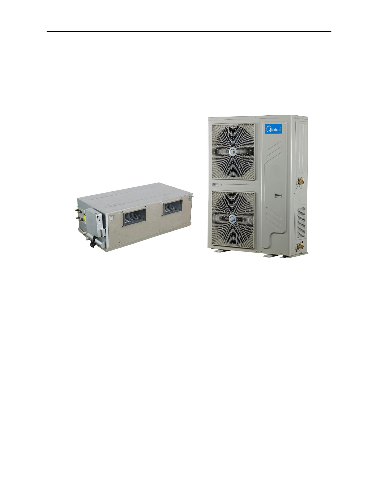
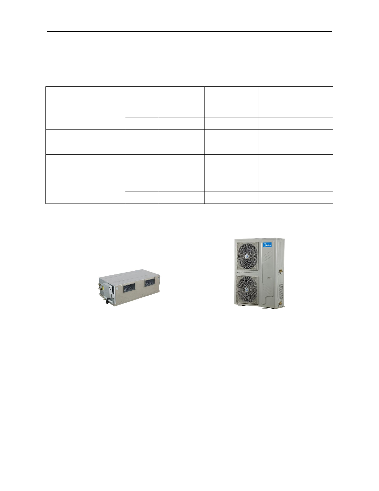
1.2 External appearance
Duct type indoor unit Side-discharge outdoor unit
Page 5
Midea R22 T1 side-discharge duct manual MCAC-RTSM-201301-01
4
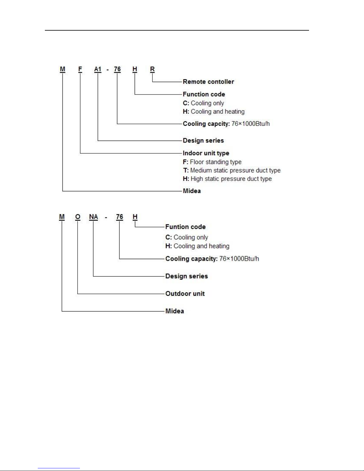
1.3 Nomenclature
Indoor unit
Outdoor unit
Page 6
MCAC-RTSM-201301-01 Midea R22 T1 side-discharge duct manual
5
2. Specification & performance
2.1Features
High capacity of cooling and heating, and energy saving.
Thin size, even can installed at limited place.
All round steel shell, for high quality protection of transportation.
Convenient installation, hidden in the ceiling, unit installation is not hindered by the location of lighting
fixtures or room structure.
Air inlet and outlet flanges are standard and easy for duct connection.
Multi diffusers from one indoor unit supply airflow to multi rooms at the same time. The unit is suitable
for various applications where there are many rooms or halls, such as restaurants, connect halls and
hotels.
High efficient scroll compressor, with thermal protectors to prevent motor overheating.
Easy maintenance.
Only remove the bottom panel, the fan-motor assembly can be drawn out.
Page 7
Midea R22 T1 side-discharge duct manual MCAC-RTSM-201301-01
6
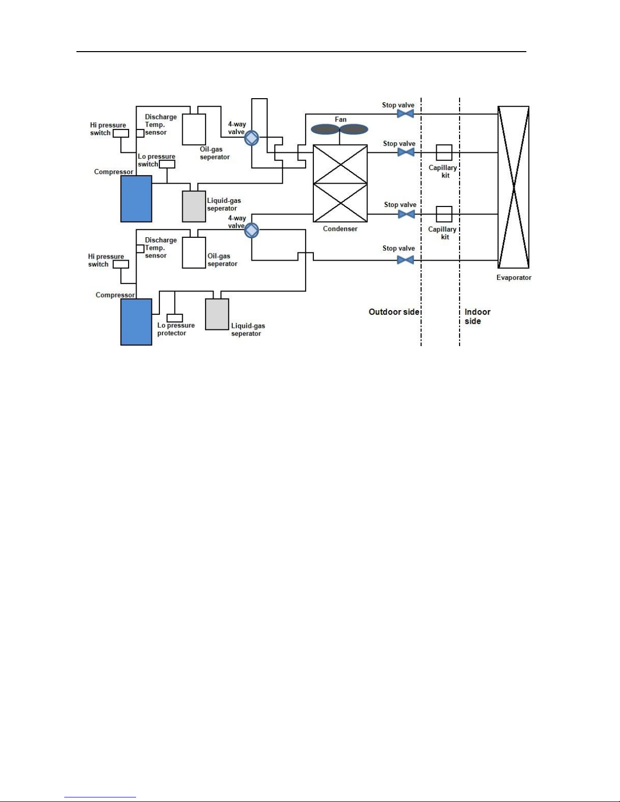
2.2 Refrigerant circuit
Compressor: R22, scroll compressor is supplied by Hitachi.
Evaporator (Heat exchanger): Copper tube and aluminum fin type heat exchanger.
Fan: Two axial fans adopting two speed levels.
High Pressure Switch: When the discharge pressure of compressor is up to 3.3MPa or higher, the
protection switch will be triggered, and if the discharge pressure is down to 2.4MPa, the protection
switch will be recovered.
Low Pressure Switch: When the suction pressure of compressor equals to 0.05MPa or less, the
protection switch will be triggered, and if the pressure is up to 0.15MPa, the protection switch will be
recovered.
Page 8
MCAC-RTSM-201301-01 Midea R22 T1 side-discharge duct manual
7
2.3 Unit structure
Page 9
Midea R22 T1 side-discharge duct manual MCAC-RTSM-201301-01
8
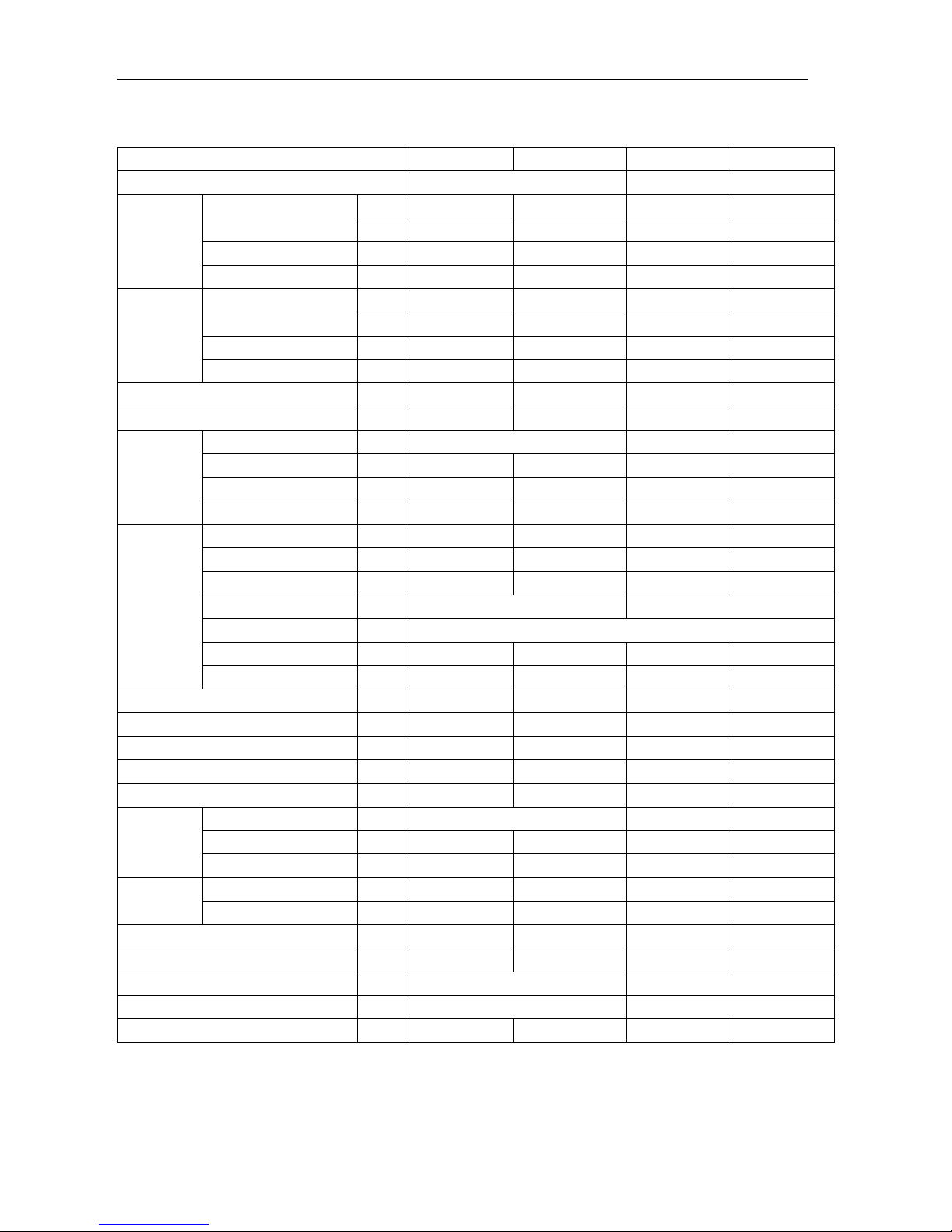
2.4 Specifications
Model
MTA1-76HR
MTA1-76CR
MTA1-96HR
MTA1-96CR
Power supply
220-240V~, 1Ph, 50Hz
220-240V~, 1Ph, 50Hz
Cooling
Capacity
Btu/h
76,000
76,000
96,000
96,000
W
22,300
22,300
28,100
28,100
Input
W
8,100
8,100
10,300
10,300
EER
W/W
2.75
2.75
2.75
2.75
Heating
Capacity
Btu/h
83,600
\
109,500
\ W 24,500
\
32,000
\
Input
W
8,000
\
10,300
\
COP
W/W
3.06 \ 3.11
\
Rated input
W
1,100
1,100
1,300
1,300
Rated current
A
4.8
4.8
5.7
5.7
Motor
Model (×quantity)
\
YDK250-4X(×2)
YDK300-4X(×2)
Input (hi/mid/lo)
W
588/484/408
588/484/408
782/677/587
782/677/587
Capacitor
\
15μF/450V
15μF/450V
15μF/450V
15μF/450V
Speed (hi/mid/lo)
r/min
930/840/770
930/840/770
1060/955/865
1060/955/865
Coil
Number of rows
\ 4 4 4 4
Tube pitch× row pitch
mm
21×13.37
21×13.37
21×13.37
21×13.37
Fin spacing
mm
1.5
1.5
1.5
1.5
Fin type \ Hydrophilic aluminum fin
Hydrophilic aluminum fin
Pipe type/size \ Inner grooved copper pipe/Ф7mm
Coil(W×H)
mm
1,202×378
1,202×378
1,202×378
1,202×378
Number of circuits
\
8+7
8+7
5+4
5+4
Indoor air flow
m3/h
4,500
4,500
5,100
5,100
External static pressure
Pa
100
100
100
100
Indoor noise level
dB(A)
55
55
55
55
Refrigerant type
\
R22
R22
R22
R22
Design pressure
MPa
3.3/2.2
3.3/2.2
3.3/2.2
3.3/2.2
Refrigerant
piping
Liquid side/ Gas side
mm
(Ф9.52/Ф19) ×2
(Ф9.52/Ф19) ×2
Max. pipe length
m
50
50
50
50
Max. difference in level
m
25
25
25
25
Connecting
wire
Power wire
\
3×2.5mm2
3×2.5mm2
3×2.5mm2
3×2.5mm2
Signal wire
\
4×1.0mm2
2×1.0mm2
4×1.0mm2
2×1.0mm2
Drain pipe size (OD)
mm
Ф41
Ф41
Ф41
Ф41
Controller
\
R51/E
R51/CE
R51/E
R51/CE
Net dimension(W×H×D)
mm
1,366×450×716
1,366×450×716
Packing dimension(W×H×D)
mm
1,555×500×875
1,555×500×875
Net/Gross weight
kg
93/105
93/105
96/108
96/108
Notes:
The test conditions: Cooling: Indoor temperature: 27°CDB, 19°CWB; Outdoor temperature: 35°CDB, 24°CWB.
Heating: Indoor temperature: 20°CDB, 15°CWB; Outdoor temperature: 7°CDB, 6°CWB.
Page 10
MCAC-RTSM-201301-01 Midea R22 T1 side-discharge duct manual
9
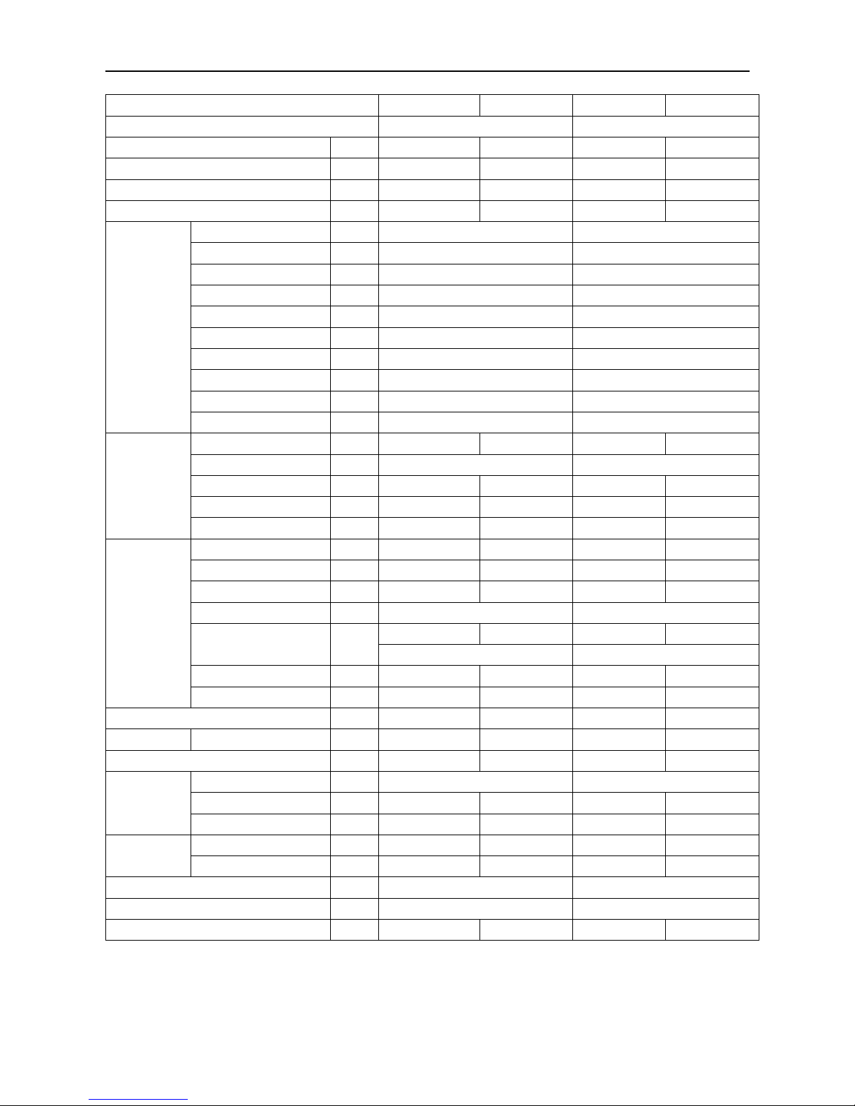
Model
MONB-76H
MONB-76C
MONB-96H
MONB-96C
Power supply
380-415V~, 3Ph, 50Hz
380-415V~, 3Ph, 50Hz
Ambient temp in cooling
°C
17~43
17~43
17~43
17~43
Ambient temp in heating
°C
-7~24
\
-7~24
\
Rated input
W
10,600
10,600
13,600
13,600
Rated current
A
17.2
17.2
21.3
21.3
Compressor
Model \ 403DH-64D2-X10J1
503DH-80D2-X10J1
Type
\
Scroll
Scroll
Qty.
\
2
2
Brand
\
Hitachi
Hitachi
Capacity W 11,800
14,900
Input W 3,600
4,400
Rated current (RLA)
A
6.3
7.5
Locked rotor Amp A 42.1
53
Thermal protector
\
Internal (UP18UC188-77G)
Internal (UP18TC16M-77G)
Refrigerant oil
ml
1,200 (SUNISO 4GSD)
1,400 (SUNISO 4GSD)
Fan
Type \ Axial fan
Axial fan
Axial fan
Axial fan
Motor Model × Quantity
\
YDK165-6E(B)×2
YDK165-6E(B)×2
Motor Input
W
280/160
280/160
280/160
280/160
Capacitor
\
10μF/450V
10μF/450V
10μF/450V
10μF/450V
Speed (Hi/Lo)
r/min
850/520
850/520
850/520
850/520
Coil
No. of rows \ 1.6
1.6 2 2
Tube pitch × row pitch
mm
21×13.37
21×13.37
21×13.37
21×13.37
Fin spacing
mm
1.5
1.5
1.5
1.5
Fin type \ Hydrophilic aluminum fin
Hydrophilic aluminum fin
Pipe size and type
mm
Ф7
Ф7
Ф7
Ф7
Inner grooved copper pipe
Inner grooved copper pipe
Coil (W×H)
mm
1,090×1,512
1,090×1,512
1,080×1,512
1,080×1,512
Number of circuits
\
18
18
18
18
Outdoor noise level
dB(A)
60
60
60
60
Refrigerant
Type/Charge
\
R22/2.3kg×2
R22/2.3kg×2
R22/2.7kg×2
R22/2.7kg×2
Design pressure
MPa
3.3/2.2
3.3/2.2
3.3/2.2
3.3/2.2
Refrigerant
piping
Liquid side/ Gas side
mm
(Ф9.52/Ф19.1) ×2
(Ф9.52/Ф19.1) ×2
Max. pipe length
m
50
50
50
50
Max. difference in level
m
25
25
25
25
Connection
wiring
Power wire
\
5×6.0mm2
5×6.0mm2
5×6.0mm2
5×6.0mm2
Signal wire
\
4×1.0mm2
2×1.0mm2
4×1.0mm2
2×1.0mm2
Net dimension (W×H×D)
mm
1,120×1,558×400
1,120×1,558×400
Packing dimension (W×H×D)
mm
1,270×1,720×565
1,270×1,720×565
Net/ Gross weight
kg
180/198
175/193
185/202
180/198
Notes:
The test conditions: Cooling: Indoor temperature: 27°CDB, 19°CWB; Outdoor temperature: 35°CDB, 24°CWB.
Heating: Indoor temperature: 20°CDB, 15°CWB; Outdoor temperature: 7°CDB, 6°CWB.
Page 11
Midea R22 T1 side-discharge duct manual MCAC-RTSM-201301-01
10
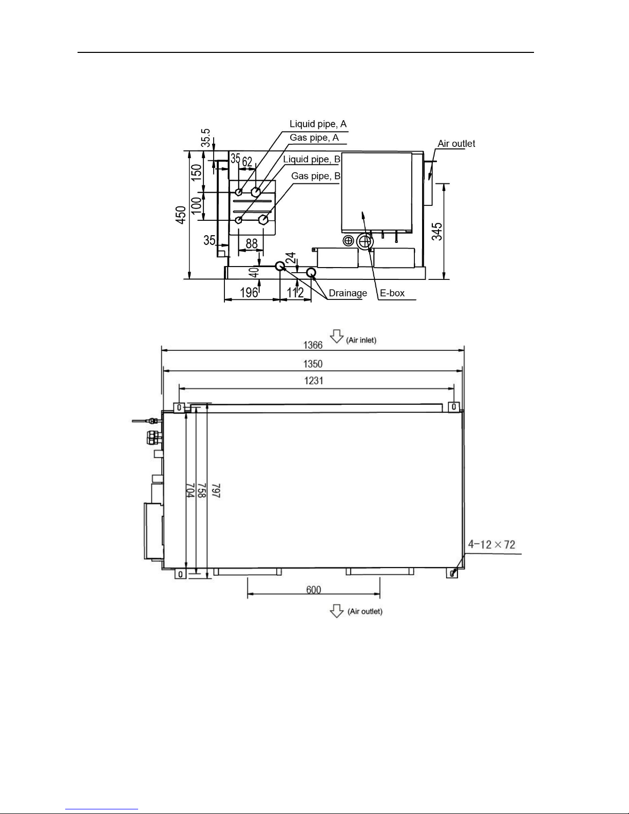
2.5 Dimension (Unit: mm)
Indoor unit
Page 12
MCAC-RTSM-201301-01 Midea R22 T1 side-discharge duct manual
11
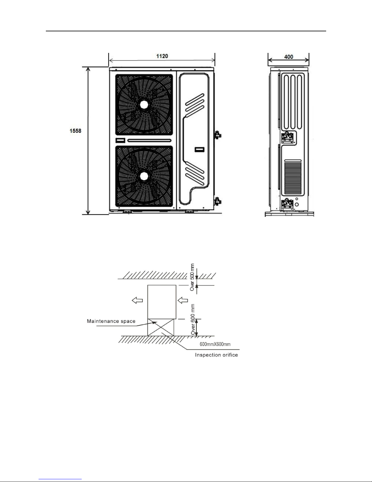
Outdoor unit
2.6 Service space
Indoor unit
Page 13
Midea R22 T1 side-discharge duct manual MCAC-RTSM-201301-01
12
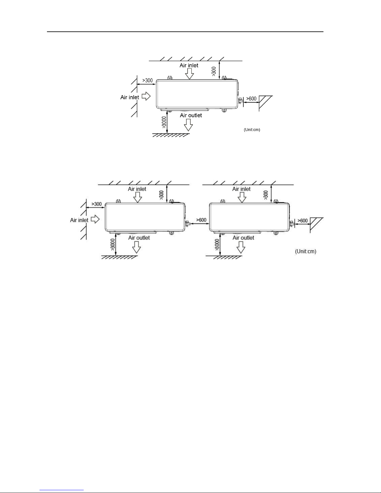
Outdoor unit
Top view of the outdoor unit (single unit installed)
Top view of the outdoor unit (multiple units installed)
Page 14
Midea R22 T1 side-discharge duct manual MCAC-UTSM-201301-01
11
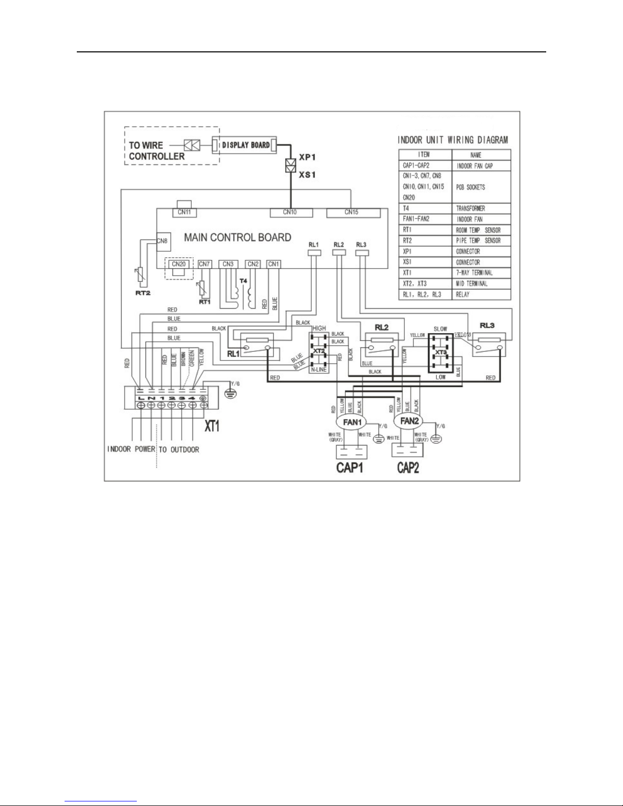
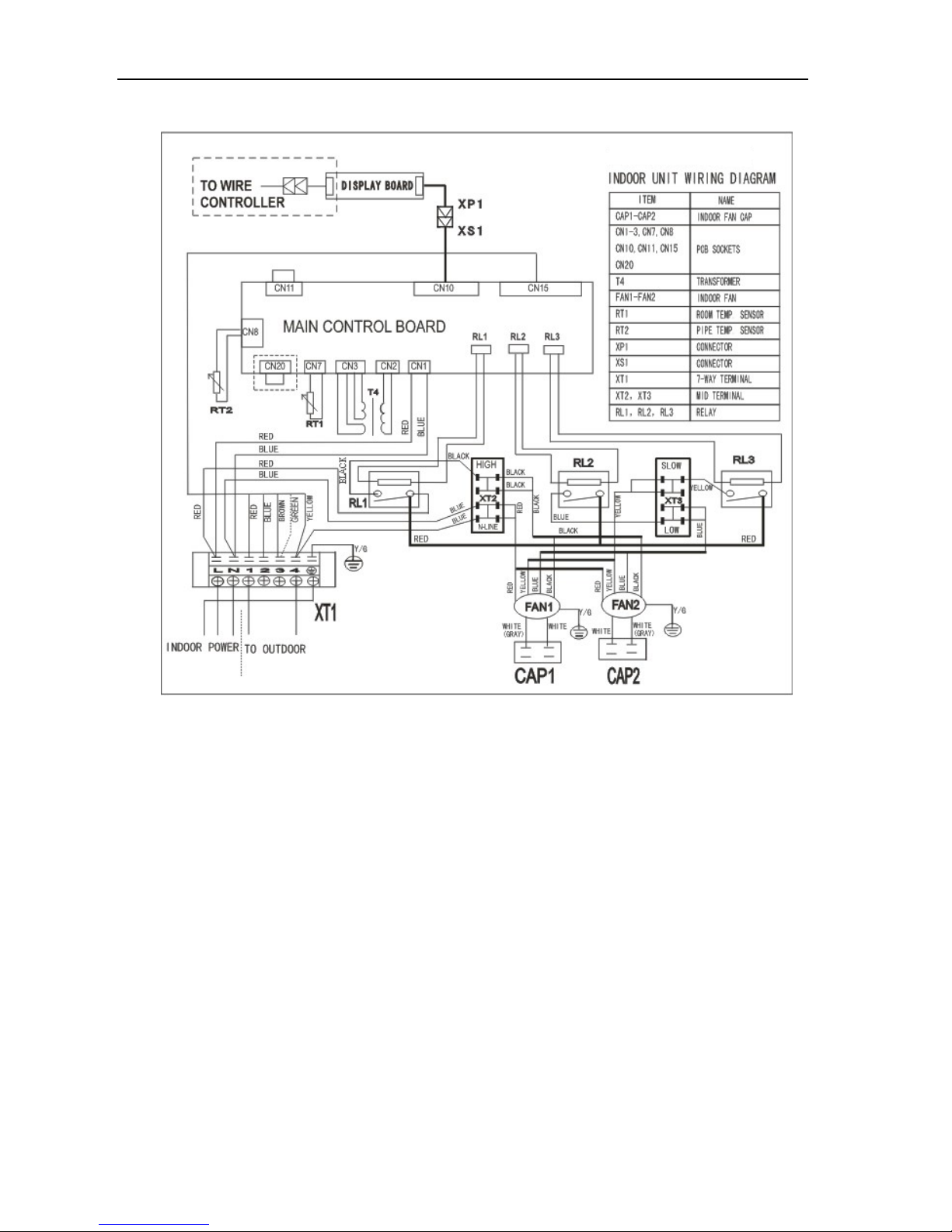
2.7 Wiring diagram
MTA1-76HR, MTA1-96HR
Page 15
Midea R22 T1 side-discharge duct manual MCAC-RTSM-201301-01
12
MTA1-76CR, MTA1-96CR
Page 16
Midea R22 T1 side-discharge duct manual MCAC-UTSM-201301-01
11
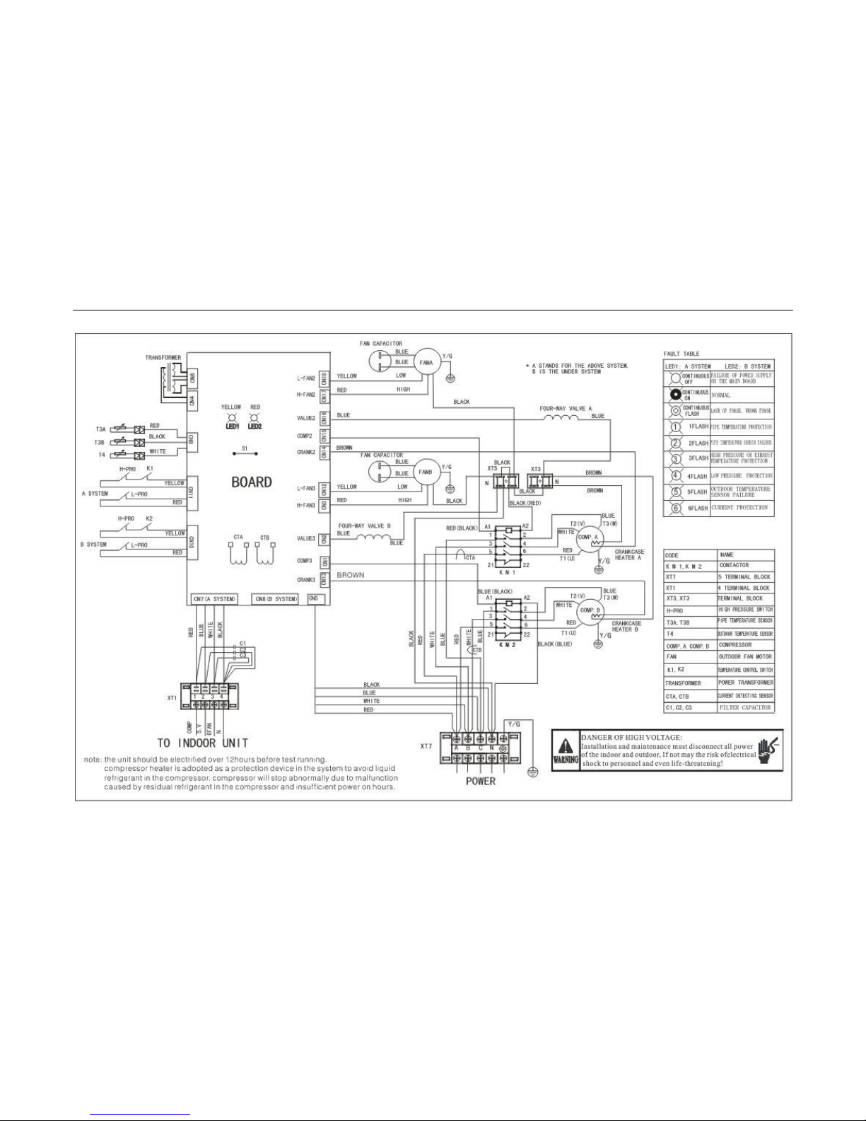
MONB-76H, MONB-96H
Page 17
Midea R22 T1 side-discharge duct manual MCAC-RTSM-201301-01
12
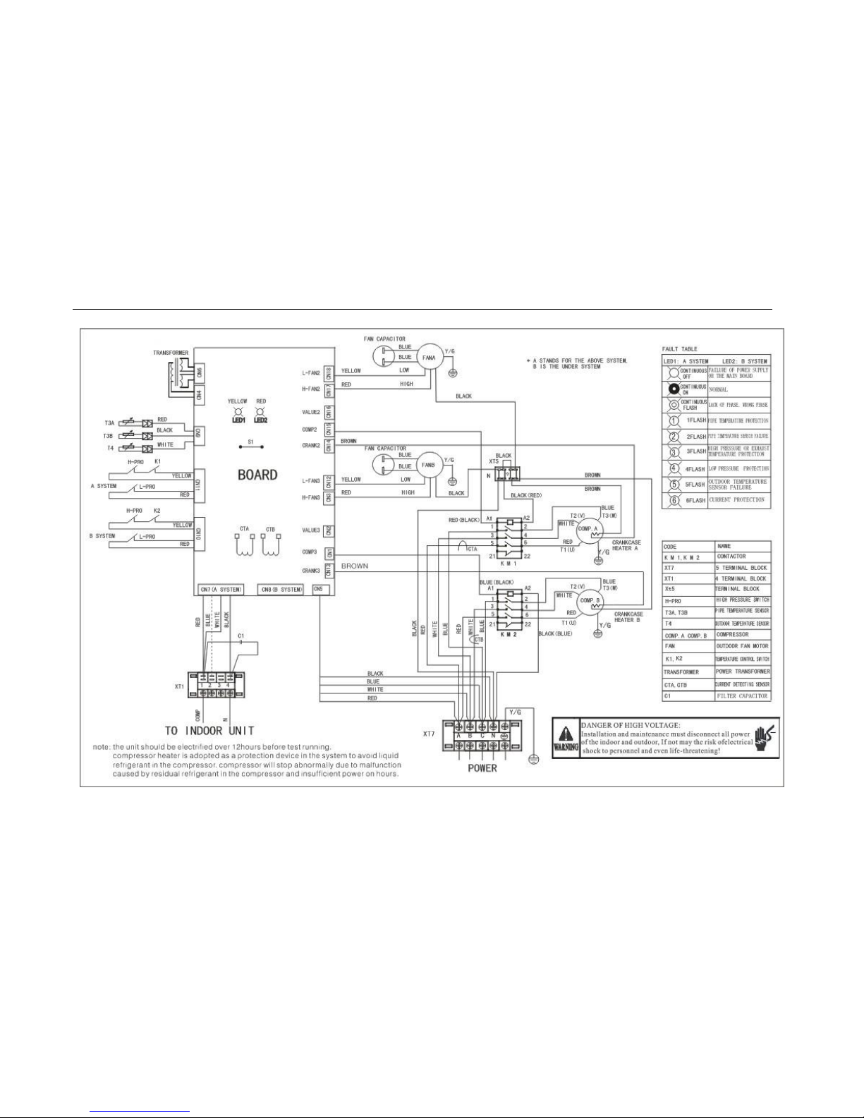
MONB-76C, MONB-96C
Page 18

MCAC-RTSM-201301-01 Midea R22 T1 side-discharge duct manual
13
2.8 Capacity tables
Cooling: MTA1-76HR
Gross Cooling Capacity (kW)
Outdoor DB(°C )
29.40
35.00
Indoor
WB(°C )
16.10
19.40
22.80
16.10
19.40
22.80
CFM
DB(℃)
TGC
SHC
PI
TGC
SHC
PI
TGC
SHC
PI
TGC
SHC
PI
TGC
SHC
PI
TGC
SHC
PI
2200
23.90
13.0
8.7
4.8
13.7
9.1
5.1
14.3
9.6
5.3
15.1
10.0
5.6
15.8
10.5
5.9
16.6
11.1
6.1
26.70
13.5
10.4
5.0
14.2
10.9
5.3
14.9
11.5
5.5
15.7
12.0
5.8
16.4
12.6
6.1
17.3
13.3
6.4
29.40
14.1
11.7
5.2
14.8
12.3
5.5
15.5
12.9
5.7
16.3
13.6
6.0
17.1
14.2
6.3
18.0
15.0
6.6
32.20
14.6
13.3
5.4
15.4
14.0
5.7
16.1
14.7
6.0
16.9
15.4
6.3
17.8
16.2
6.6
18.7
17.0
6.9
2450
23.90
15.2
10.1
5.6
16.0
10.7
5.9
16.8
11.2
6.2
17.6
11.7
6.5
18.5
12.3
6.8
19.4
12.9
7.2
26.70
15.8
12.2
5.9
16.6
12.8
6.2
17.4
13.4
6.5
18.3
14.1
6.8
19.2
14.8
7.1
20.2
15.5
7.5
29.40
16.5
13.7
6.1
17.3
14.4
6.4
18.1
15.1
6.7
19.0
15.9
7.1
20.0
16.7
7.4
21.0
17.5
7.8
32.20
17.1
15.6
6.3
18.0
16.3
6.7
18.9
17.2
7.0
19.8
18.0
7.3
20.8
18.9
7.7
21.8
19.9
8.1
2650
23.90
17.8
11.9
6.6
18.7
12.5
6.9
19.6
13.1
7.3
20.6
13.7
7.6
21.6
14.4
8.0
22.7
15.1
8.4
26.70
18.5
14.2
6.9
19.4
15.0
7.2
20.4
15.7
7.6
21.4
16.5
7.9
22.5
17.3
8.3
23.6
18.2
8.8
29.40
19.1
15.9
7.1
20.0
16.7
7.4
21.0
17.5
7.8
22.1
18.4
8.2
23.2
19.3
8.6
24.3
20.3
9.0
32.20
19.6
17.9
7.3
20.6
18.7
7.6
21.7
19.7
8.0
22.7
20.7
8.4
23.9
21.7
8.8
25.1
22.8
9.3
2900
23.90
20.2
13.5
7.5
21.2
14.2
7.9
22.3
14.9
8.3
23.4
15.6
8.7
24.6
16.4
9.1
25.8
17.2
9.6
26.70
20.8
16.0
7.7
21.9
16.8
8.1
23.0
17.7
8.5
24.1
18.6
8.9
25.3
19.5
9.4
26.6
20.5
9.8
29.40
21.5
17.9
7.9
22.5
18.8
8.3
23.7
19.7
8.8
24.8
20.7
9.2
26.1
21.7
9.7
27.4
22.8
10.1
32.20
22.1
20.1
8.2
23.2
21.1
8.6
24.4
22.2
9.0
25.6
23.3
9.5
26.9
24.4
10.0
28.2
25.6
10.4
Notes:
DB= Dry Bulb temperature; WB= Wet Bulb Temperature
TGC= Total Cooling Capacity (Unit: kW)
SHC= Sensible Heating Capacity (Unit: kW)
PI = Power Input (Unit: kW)
Page 19
Midea R22 T1 side-discharge duct manual MCAC-RTSM-201301-01
14
Outdoor DB(°C )
40.60
46.10
Indoor
WB(°C )
16.10
19.40
22.80
16.10
19.40
22.80
CFM
DB(°C )
TGC
SHC
PI
TGC
SHC
PI
TGC
SHC
PI
TGC
SHC
PI
TGC
SHC
PI
TGC
SHC
PI
2200
23.90
11.7
7.8
6.8
12.3
8.2
7.2
12.9
8.6
7.5
13.6
9.1
7.9
14.3
9.5
8.3
15.0
10.0
8.7
26.70
12.2
9.4
7.1
12.8
9.9
7.4
13.5
10.3
7.8
14.1
10.9
8.2
14.8
11.4
8.6
15.6
12.0
9.1
29.40
12.7
10.6
7.4
13.3
11.1
7.7
14.0
11.7
8.1
14.7
12.2
8.5
15.4
12.9
9.0
16.2
13.5
9.4
32.20
13.2
12.0
7.7
13.9
12.6
8.1
14.6
13.2
8.5
15.3
13.9
8.9
16.0
14.6
9.3
16.8
15.3
9.8
2450
23.90
13.7
9.2
8.0
14.4
9.6
8.4
15.1
10.1
8.8
15.9
10.6
9.2
16.7
11.1
9.7
17.5
11.7
10.2
26.70
14.3
11.0
8.3
15.0
11.5
8.7
15.7
12.1
9.1
16.5
12.7
9.6
17.4
13.3
10.1
18.2
14.0
10.6
29.40
14.8
12.4
8.6
15.6
13.0
9.1
16.4
13.6
9.5
17.2
14.3
10.0
18.0
15.0
10.5
18.9
15.8
11.0
32.20
15.4
14.0
9.0
16.2
14.7
9.4
17.0
15.5
9.9
17.9
16.2
10.4
18.8
17.1
10.9
19.7
17.9
11.5
2650
23.90
16.1
10.7
9.3
16.9
11.2
9.8
17.7
11.8
10.3
18.6
12.4
10.8
19.5
13.0
11.3
20.5
13.7
11.9
26.70
16.7
12.8
9.7
17.5
13.5
10.2
18.4
14.2
10.7
19.3
14.9
11.2
20.3
15.6
11.8
21.3
16.4
12.4
29.40
17.2
14.3
10.0
18.1
15.1
10.5
19.0
15.8
11.0
19.9
16.6
11.6
20.9
17.4
12.2
22.0
18.3
12.8
32.20
17.7
16.1
10.3
18.6
16.9
10.8
19.5
17.8
11.4
20.5
18.6
11.9
21.5
19.6
12.8
22.6
20.6
13.1
2900
23.90
18.2
12.2
10.6
19.2
12.8
11.1
20.1
13.4
11.7
21.1
14.1
12.3
22.2
14.8
13.1
23.3
15.5
13.5
26.70
18.8
14.5
10.9
19.7
15.2
11.5
20.7
15.9
12.0
21.8
16.7
12.6
22.8
17.6
13.5
24.0
18.5
13.9
29.40
19.4
16.1
11.3
20.3
16.9
11.8
21.3
17.8
12.4
22.4
18.7
13.0
23.5
19.6
13.9
24.7
20.6
14.4
32.20
19.9
18.1
11.6
20.9
19.0
12.2
22.0
20.0
12.8
23.1
21.0
13.4
24.2
22.0
14.4
25.5
23.1
14.8
Notes:
DB= Dry Bulb temperature; WB= Wet Bulb Temperature
TGC= Total Cooling Capacity (Unit: kW)
SHC= Sensible Heating Capacity (Unit: kW)
PI = Power Input (Unit: kW)
Page 20

MCAC-RTSM-201301-01 Midea R22 T1 side-discharge duct manual
15
Cooling: MFA1-96
Gross Cooling Capacity (kW)
Outdoor DB(°C )
29.40
35.00
Indoor
WB(°C )
16.10
19.40
22.80
16.10
19.40
22.80
CFM
DB(°C )
TGC
SHC
PI
TGC
SHC
PI
TGC
SHC
PI
TGC
SHC
PI
TGC
SHC
PI
TGC
SHC
PI
2470
23.90
16.2
10.8
6.0
17.1
11.4
6.3
17.9
11.9
6.6
18.8
12.5
7.0
19.7
13.2
7.3
20.7
13.8
7.7
26.70
16.9
13.0
6.3
17.7
13.6
6.6
18.6
14.3
6.9
19.6
15.0
7.2
20.5
15.8
7.6
21.6
16.6
8.0
29.40
17.6
14.6
6.5
18.4
15.4
6.8
19.4
16.1
7.2
20.3
16.9
7.5
21.4
17.8
7.9
22.4
18.7
8.3
32.20
18.3
16.6
6.8
19.2
17.4
7.1
20.1
18.3
7.5
21.2
19.2
7.8
22.2
20.2
8.2
23.3
21.2
8.6
2700
23.90
19.0
12.7
7.0
20.0
13.3
7.4
20.9
14.0
7.8
22.0
14.7
8.1
23.1
15.4
8.6
24.3
16.2
9.0
26.70
19.8
15.2
7.3
20.7
16.0
7.7
21.8
16.8
8.1
22.9
17.6
8.5
24.0
18.5
8.9
25.2
19.4
9.3
29.40
20.6
17.1
7.6
21.6
18.0
8.0
22.7
18.9
8.4
23.8
19.8
8.8
25.0
20.8
9.3
26.2
21.9
9.7
32.20
21.4
19.4
7.9
22.4
20.4
8.3
23.6
21.4
8.7
24.7
22.5
9.2
26.0
23.6
9.6
27.3
24.8
10.1
3000
23.90
22.2
14.8
8.2
23.3
15.6
8.6
24.5
16.3
9.1
25.7
17.2
9.5
27.0
18.0
10.0
28.4
18.9
10.5
26.70
23.1
17.8
8.6
24.3
18.7
9.0
25.5
19.6
9.4
26.8
20.6
9.9
28.1
21.6
10.4
29.5
22.7
10.9
29.40
23.8
19.8
8.8
25.0
20.8
9.3
26.3
21.9
9.7
27.6
23.0
10.2
28.9
24.1
10.7
30.4
25.3
11.3
32.20
24.5
22.3
9.1
25.8
23.4
9.5
27.0
24.6
10.0
28.4
25.8
10.5
29.8
27.1
11.0
31.3
28.5
11.6
3300
23.90
25.3
16.8
9.4
26.5
17.7
9.8
27.9
18.6
10.3
29.2
19.5
10.8
30.7
20.5
11.4
32.2
21.5
11.9
26.70
26.0
20.0
9.6
27.3
21.0
10.1
28.7
22.1
10.6
30.1
23.2
11.2
31.6
24.3
11.7
33.2
25.5
12.3
29.40
26.8
22.3
9.9
28.1
23.5
10.4
29.5
24.6
10.9
31.0
25.9
11.5
32.6
27.1
12.1
34.2
28.5
12.7
32.20
27.6
25.1
10.2
29.0
26.3
10.7
30.4
27.7
11.3
32.0
29.1
11.8
33.6
30.5
12.4
35.2
32.0
13.0
Notes:
DB= Dry Bulb temperature; WB= Wet Bulb Temperature
TGC= Total Cooling Capacity (Unit: kW)
SHC= Sensible Heating Capacity (Unit: kW)
PI = Power Input (Unit: kW)
Page 21
Midea R22 T1 side-discharge duct manual MCAC-RTSM-201301-01
16
Gross Cooling Capacity (kW)
Outdoor DB(°C )
40.60
46.10
Indoor
WB(°C )
16.10
19.40
22.80
16.10
19.40
22.80
CFM
DB(°C )
TGC
SHC
PI
TGC
SHC
PI
TGC
SHC
PI
TGC
SHC
PI
TGC
SHC
PI
TGC
SHC
PI
2470
23.90
14.7
9.8
8.8
15.5
10.3
9.3
16.3
10.8
9.8
17.1
11.4
10.2
17.9
11.9
10.7
18.8
12.5
11.3
26.70
15.3
11.8
9.2
16.1
12.4
9.7
16.9
13.0
10.1
17.7
13.7
10.6
18.6
14.3
11.2
19.6
15.0
11.7
29.40
15.9
13.3
9.6
16.7
13.9
10.0
17.6
14.6
10.5
18.5
15.4
11.1
19.4
16.1
11.6
20.3
17.0
12.2
32.20
16.6
15.1
9.9
17.4
15.8
10.4
18.3
16.6
11.0
19.2
17.4
11.5
20.2
18.3
12.1
21.2
19.2
12.7
2700
23.90
17.2
11.5
10.3
18.1
12.1
10.9
19.0
12.7
11.4
20.0
13.3
12.0
21.0
14.0
12.6
22.0
14.7
13.2
26.70
17.9
13.8
10.8
18.8
14.5
11.3
19.8
15.2
11.9
20.8
16.0
12.5
21.8
16.8
13.1
22.9
17.6
13.7
29.40
18.7
15.5
11.2
19.6
16.3
11.7
20.6
17.1
12.3
21.6
18.0
13.0
22.7
18.9
13.6
23.8
19.8
14.3
32.20
19.4
17.6
11.6
20.4
18.5
12.2
21.4
19.4
12.8
22.5
20.4
13.5
23.6
21.4
14.1
24.8
22.5
14.9
3000
23.90
20.2
13.4
12.1
21.2
14.1
12.7
22.2
14.8
13.3
23.4
15.6
14.0
24.5
16.3
14.7
25.7
17.2
15.4
26.70
21.0
16.1
12.6
22.0
16.9
13.2
23.1
17.8
13.9
24.3
18.7
14.6
25.5
19.6
15.3
26.8
20.6
16.1
29.40
21.6
18.0
13.0
22.7
18.9
13.6
23.8
19.9
14.3
25.0
20.8
15.0
26.3
21.9
15.8
27.6
23.0
16.5
32.20
22.3
20.2
13.4
23.4
21.2
14.0
24.5
22.3
14.7
25.8
23.4
15.5
27.1
24.6
16.2
28.4
25.8
17.0
3300
23.90
22.9
15.3
13.8
24.1
16.0
14.4
25.3
16.8
15.2
26.5
17.7
15.9
27.9
18.6
16.7
29.3
19.5
17.6
26.70
23.6
18.2
14.2
24.8
19.1
14.9
26.0
20.0
15.6
27.3
21.0
16.4
28.7
22.1
17.2
30.1
23.2
18.1
29.40
24.3
20.3
14.6
25.5
21.3
15.3
26.8
22.3
16.1
28.2
23.5
16.9
29.6
24.6
17.7
31.0
25.9
18.6
32.20
25.0
22.8
15.0
26.3
23.9
15.8
27.6
25.1
16.6
29.0
26.4
17.4
30.4
27.7
18.3
32.0
29.1
19.2
Notes:
DB= Dry Bulb temperature; WB= Wet Bulb Temperature
TGC= Total Cooling Capacity (Unit: kW)
SHC= Sensible Heating Capacity (Unit: kW)
PI = Power Input (Unit: kW)
Page 22
Midea R22 T1 side-discharge duct manual MCAC-UTSM-201301-01
11
2.9 Electric characteristics
Model
Indoor unit
Power supply
IFM
Hz
Voltage
Min.
Max.
MCA
MFA
kW
FLA
MTA1-76HR
50
220~240
198
254
6.2
15
0.5
4.96
MTA1-76CR
50
220~240
198
254
6.2
15
0.5
4.96
MTA1-96HR
50
220~240
198
254
8.6
15
0.6
6.9
MTA1-96CR
50
220~240
198
254
8.6
15
0.6
6.9
Notes:
MCA: Min. Current Amps. (A)
MFA: Max. Fuse Amps. (A)
kW: Fan Motor Rated Output (kW)
FLA: Full Load Amps. (A)
IFM: Indor Fan Motor
Model
Outdoor Unit
Power Supply
Compressor
OFM
Hz
Voltage
Min.
Max.
MCA
TOCA
MFA
MSC
RLA
kW
FLA
MONB-76H
50
380~415
342
440
15.5
19.3
23.2
42.1
6.3
0.33
2.7
MONB-76C
50
380~415
342
440
15.5
19.3
23.2
42.1
6.3
0.33
2.7
MONB-96H
50
380~415
342
440
19.8
23.7
27.5
53
7.5
0.33
2.7
MONB-96C
50
380~415
342
440
19.8
23.7
27.5
53
7.5
0.33
2.7
Notes:
MCA: Min. Current Amps. (A) MFA: Max. Fuse Amps. (A)
TOCA: Total Over-current Amps. (A) MSC: Max. Starting Amps. (A)
RLA: Rated Locked Amps. (A) OFM: Outdoor Fan Motor
kW: Rated Motor Output (Kw) FLA: Full Load Amps. (A)
Page 23
Midea R22 T1 side-discharge duct manual MCAC-RTSM-201301-01
12
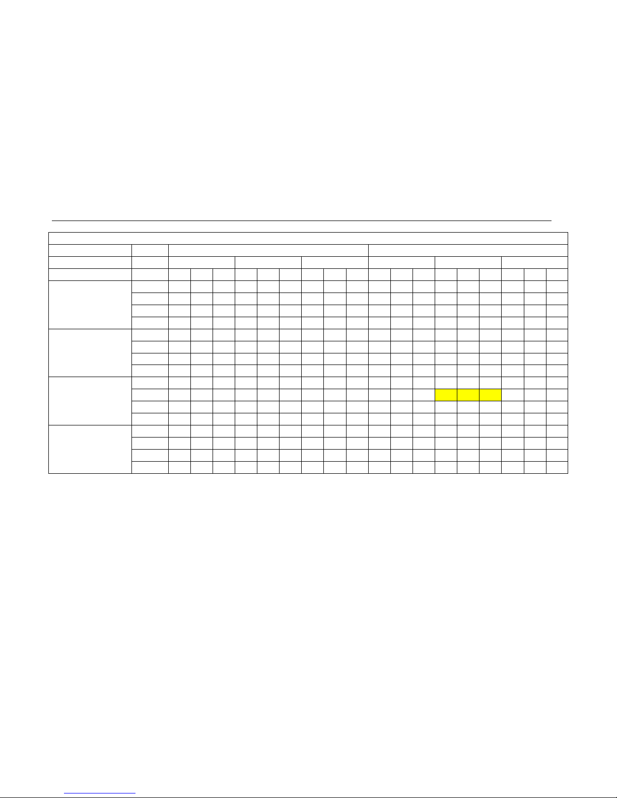
2.10 Sound levels
Indoor units
Model
Noise level
MTA1-76HR
55 dB(A)
MTA1-76CR
55 dB(A)
MTA1-96HR
55 dB(A)
MTA1-96CR
55 dB(A)
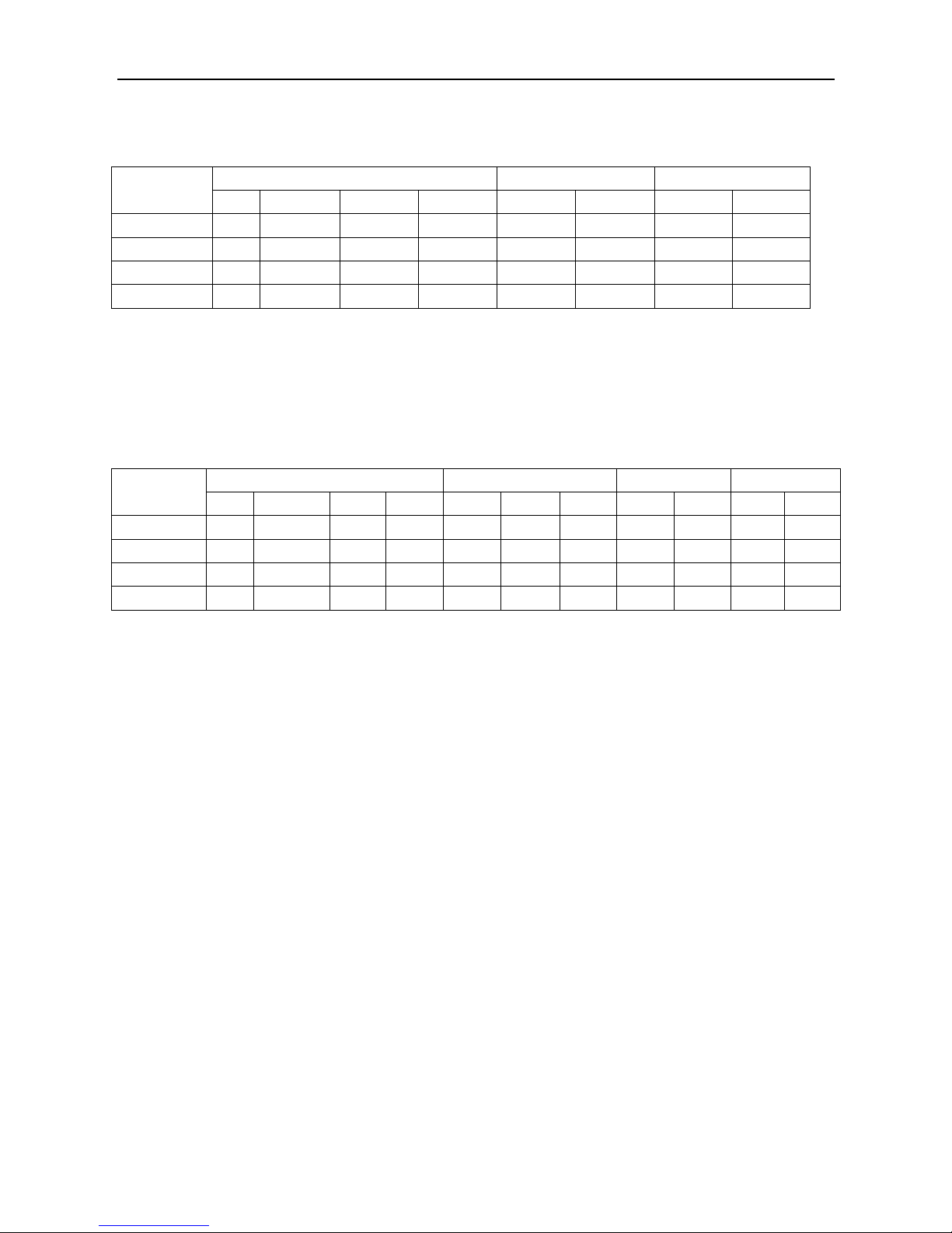
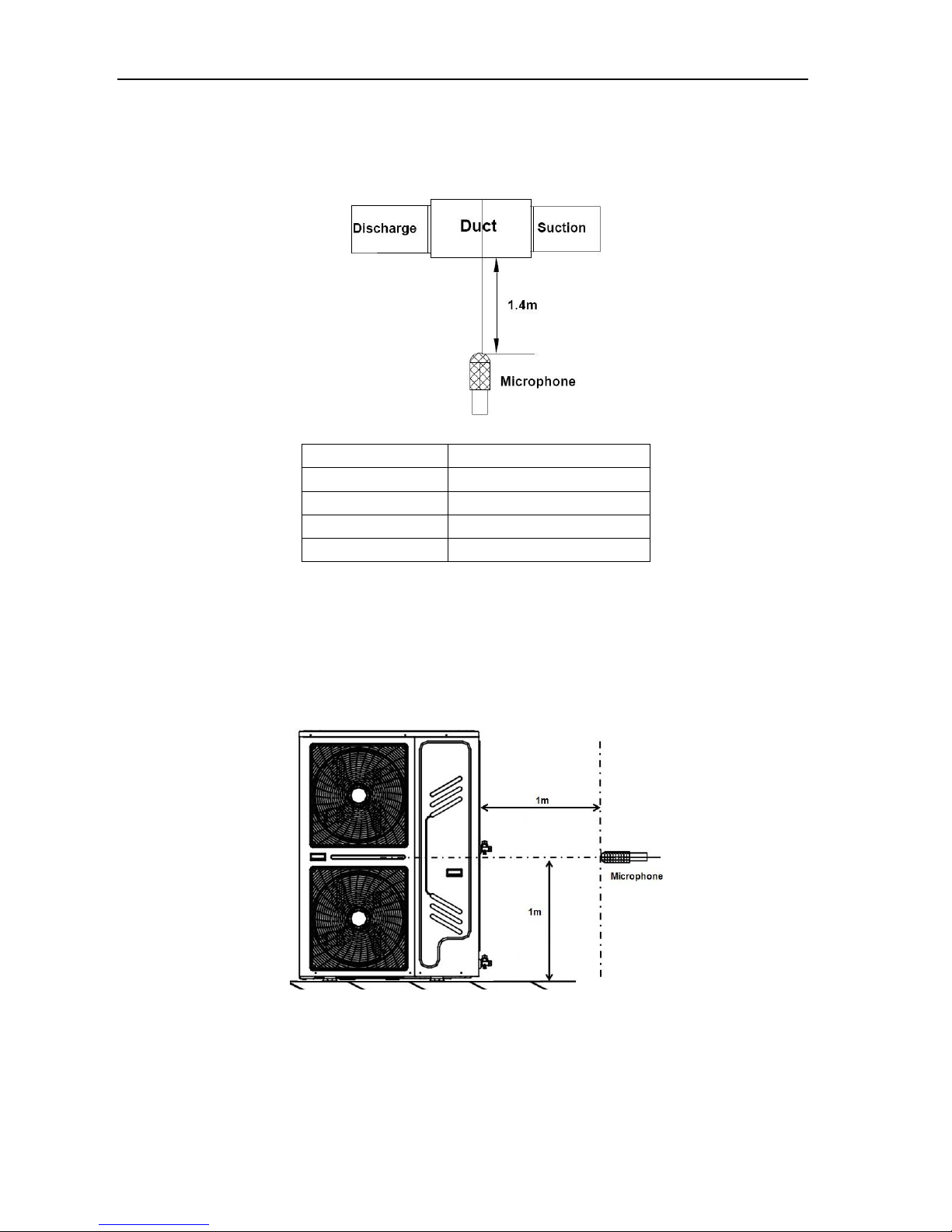
Outdoor units
As the following picture, the nominal noise level is the maximum value between the tested value from
three sides.
Page 24
MCAC-RTSM-201301-01 Midea R22 T1 side-discharge duct manual
13
Model
Noise level
MONB-76H
60 dB(A)
MONB-76C
60 dB(A)
MONB-96H
60 dB(A)
MONB-96H
60 dB(A)
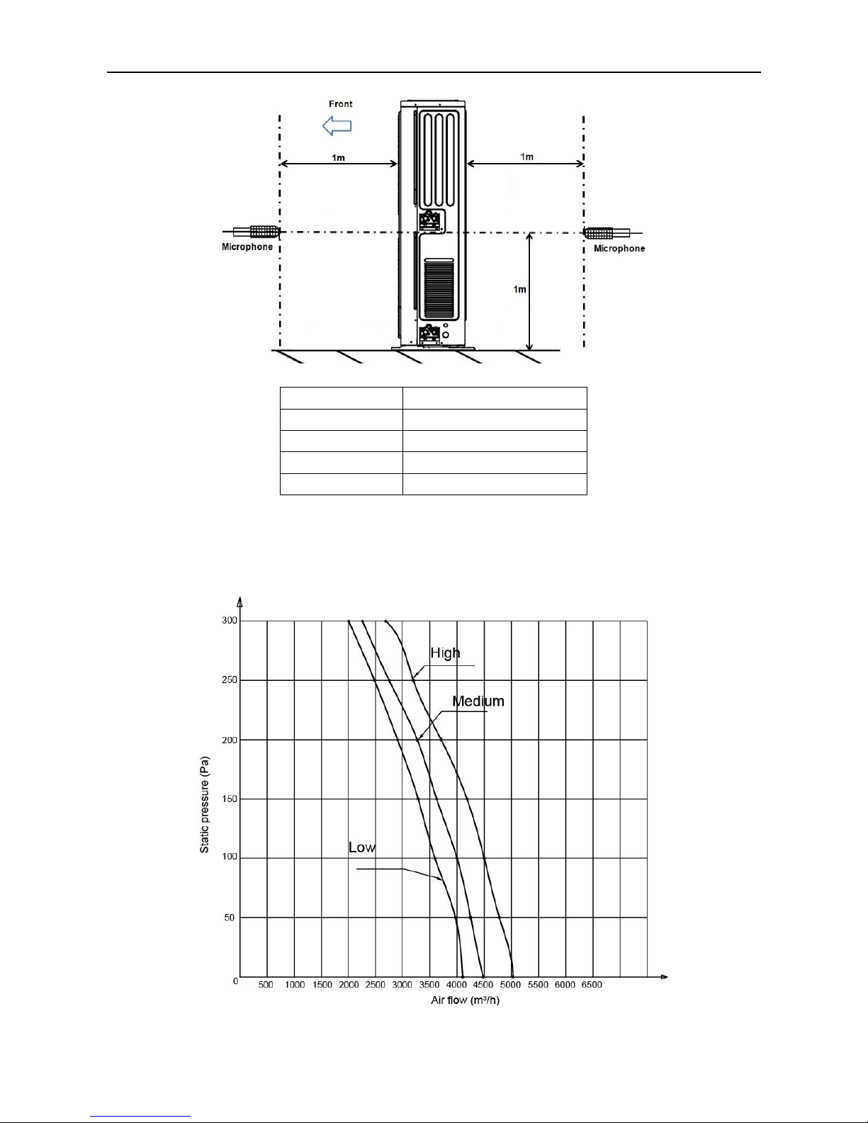
2.11 Static pressure curve
MTA1-76
Page 25
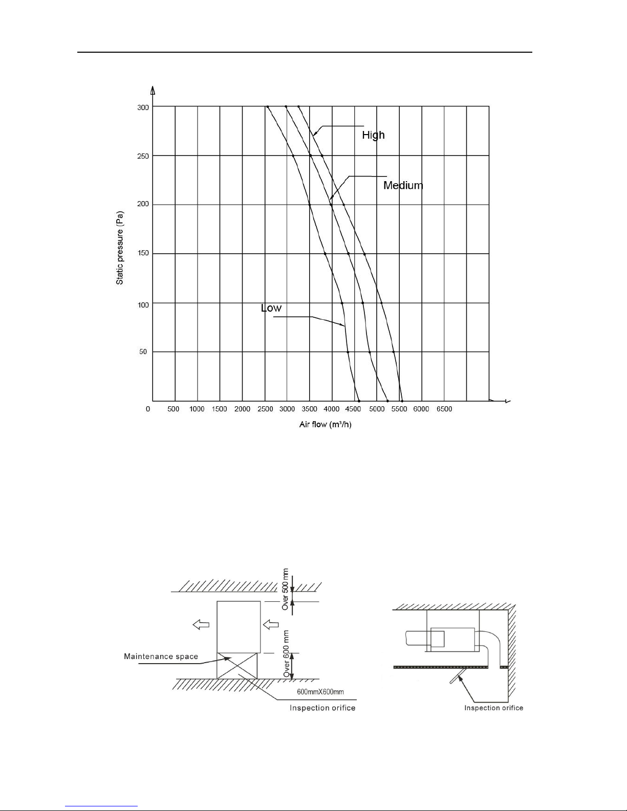
Midea R22 T1 side-discharge duct manual MCAC-RTSM-201301-01
14
MTA1-96
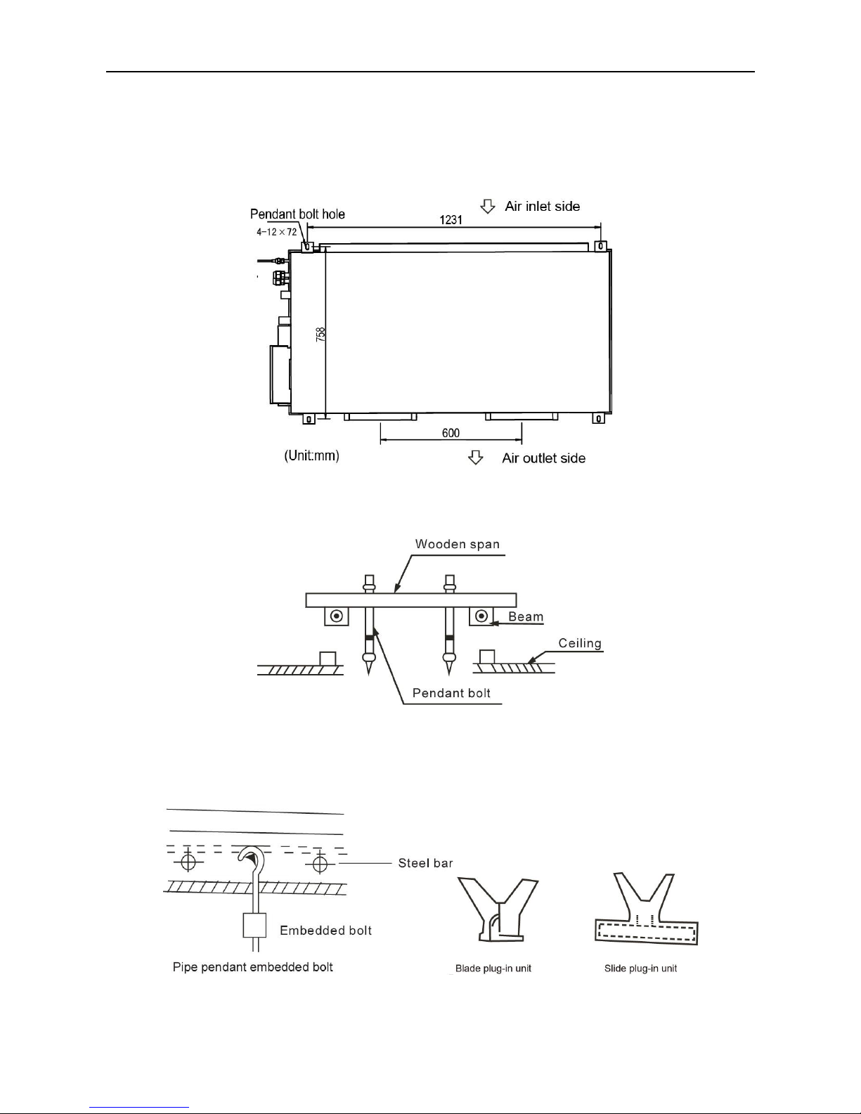
3. Installation
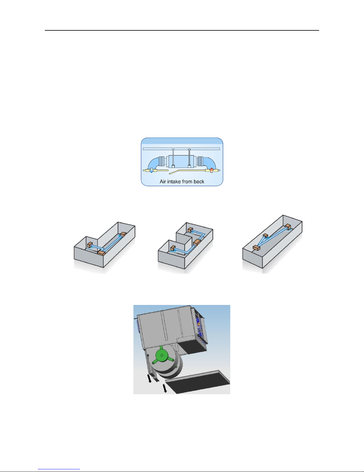
3.1 Installating indoor units
As the following picture, when install the indoor unit, select the enough solid and level site with
enough space for installation and maintance.
The inspection orifice should be larger than the units.
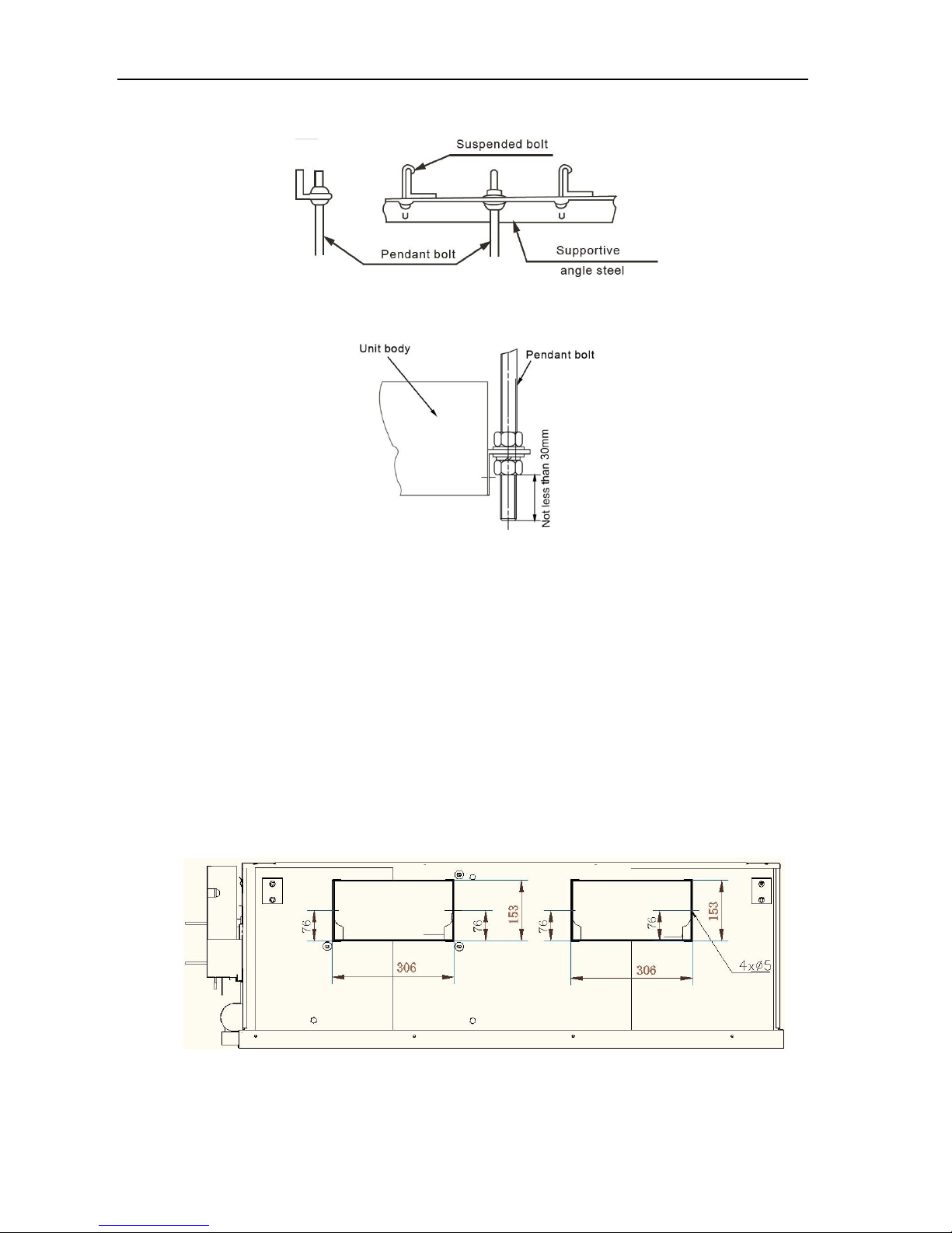
Page 26
MCAC-RTSM-201301-01 Midea R22 T1 side-discharge duct manual
15
Use Ф10 or bigger screws. The screw material is high-quality carbon steel whose surface is zinc
plated or undergoes other anti-rust treatment, or stainless steel.
Fix the pendant bolts firmly and reliably in light of the specifice situsation.
The pendant bolt hole figure is as following picture.
When the pandant bolt is fixed in wooden structure, please put rectanglar sticks across the
beams, and set pendant bolts.
When in the new concrete roughcast environment, please use embedded bolts, embedded
pulling plugs and stick harness. On steel bar have some holes to hang pipe and embed screw
bolts.
.
Page 27
Midea R22 T1 side-discharge duct manual MCAC-RTSM-201301-01
16
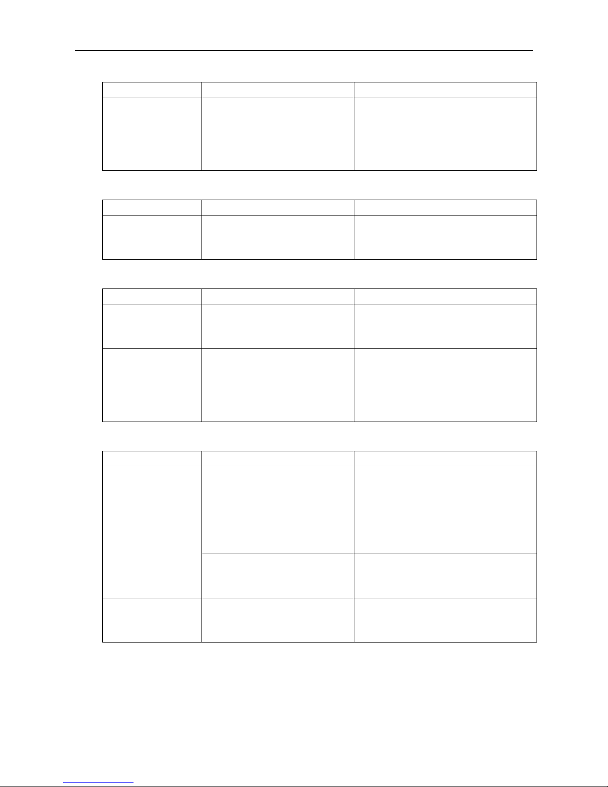
When in steel beam and girder structure, set and use supportive angle steel.
After install the indoor units, use a hoisting device to hoist the indoor unit, and align it with the
installation screws to adjust the horizontality. Finally, Tighten the screws.
3.2 Designing and connecting the duct
The duct accessories and materials must be produced by professional manufacturers.
Int order to prevent air flow shoting, do not set the air inlet orifice near the air outlet orifice.
Install a filter at an easy-to-maintain place such as intake pipe. If without the filter, the duct will
gether on the air heat exchanger and lead to fault and water leak of the air conditioner.
In order to suppress noise effectively, install noise suppression and sound insulation devices,
especially in the noise-sensitive spaces such as meeting rooms.
For connection of the flange plane, use non-flammable canvas adapter to prevent transmission
of vibration. Use M6×20 screws (configured on site) for connection.
View of air outlet side
Page 28

MCAC-RTSM-201301-01 Midea R22 T1 side-discharge duct manual
17
View of top side
View of air inlet side
All pipelines must be connected closely and soundly without leak of air. The pipelines must be
adiabatic and free from condensation. The key points of duct connection are as following picture.
Page 29

Midea R22 T1 side-discharge duct manual MCAC-RTSM-201301-01
18
3.3 Installing outdoor units
When installing the unit, leave a space for installation and maintenance shown in the following
figure. Install the power supply at the right side of the outdoor unit.
In case any obstacles exist above the outdoor unit, such obstacles must be 2000mm above the
outdoor unit.
If miscellaneous articles are piled around the outdoor unit, such articles must be 400mm below
the top of outdoor unit.
Top view of the outdoor unit (single unit installed)
Top view of the outdoor unit (multiple units installed)
Use 4 steel ropes, diameter 6mm, or bigger size to hoist the outdoor uint and convey it into the
room.
In order to prevent scratch and deformity the outdoor unit, apply a guard board to the surface of
contact between the steel ropes and the unit.
Remove the cushion for using in the transport after finishing the transport.
Page 30

MCAC-RTSM-201301-01 Midea R22 T1 side-discharge duct manual
19
1 unit should be fixed 4 screws which match with M12 foundation bolts.
The distance of the foundation bolt is shown in following figure.
Snow protection facilities must be installed in the snowfall areas. If the snow protection facilities are
incomplete, faults may occur. In order to prevent influence caused by snow, set up raised pavilion,
and install sheds at the air inlet and aire outlet.
Notes:
It is dangers that the outdoor unit is fixed by mouting on the wall.
Page 31

Midea R22 T1 side-discharge duct manual MCAC-RTSM-201301-01
20
3.4 Connecting refrigerant pipe
Size of the outdoor unit pipes.
Model
Gas side (mm)
Liquid side (mm)
MONB-76H
Ф9.52
Ф19.0
MONB-76C
Ф9.52
Ф19.0
MONB-96H
Ф9.52
Ф19.0
MONB-96C
Ф9.52
Ф19.0
Allowed length of refrigerant pipe and height difference.
Allowed value
Max. Actual length of pipe
50m
Max. Height difference between indoor
unit and outdoor unit.
Outdoor unit upper
25m
Outdoor unit lower
20m
Max. quantity of bends
15
Page 32

MCAC-RTSM-201301-01 Midea R22 T1 side-discharge duct manual
21
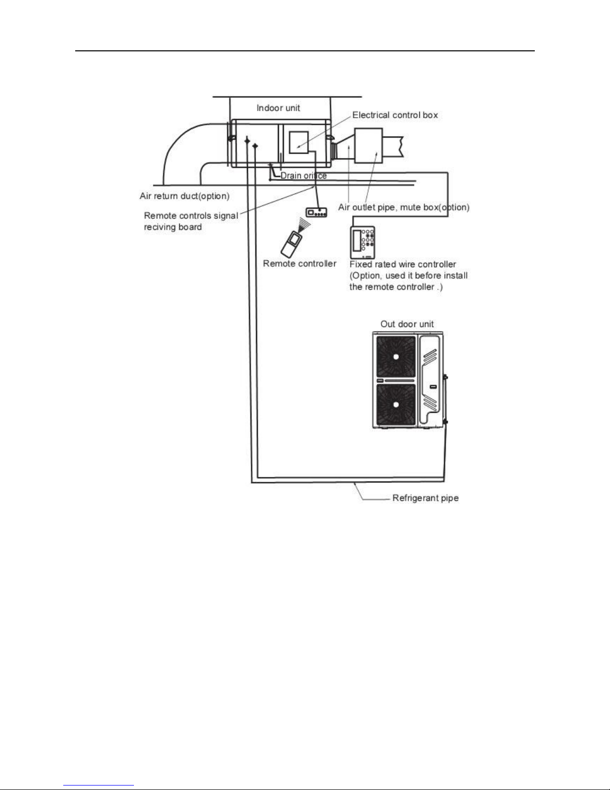
Schematic diagram of connection between indoor unit and outdoor unit.
The indoor unit and outdoor unita are categorized int system A and system B. When installing
and connecting the indoor unit and outdoor unit, identify the label carefully , and make sure that
indoor unit corresponds to the outdoor unit exactly. Otherwise, it may lead to fault of the air
conditioner.
The throtting assemble (capillay kit) should be directly connected with indoor unit liquid pipe joint
of system A and B, at the same time it must be fixed horizontally.
In the process of installing the connective pipe, do not let the air, dust, water or foreign
substance intrude into the pipeline sysem.
Trash and foreign matters may come into the pipe in the process of pipe intallation. Be sure to
blow them off with niltrogen before connecting the pipe to the outdoor units.
Use high-pressure niltrogen to clean the pipelines. Do not use the refrigerant of the outdoor unit
for cleaning.
Install the connective pipe only after fixing the indoor and outdoor units.
Keep dry when installing the pipe, and do not let moist intrude into the pipeline system.
Cut the pipe with a pipe cutter.
Page 33

Midea R22 T1 side-discharge duct manual MCAC-RTSM-201301-01
22
Insert a flare nut into the pipe and flare the pipe.
Outside Diameter
(mm)
A (mm)
Max.
Min.
Ф9.52
12.4
12.0
Ф19.1
23.3
22.9
Put the connecting tubing at the proper position, wrench the nuts with hands, then fasten it with a
wrench. Too large torque will harm the bellmouthing and too small will cause leakage, so it is
needed to determine the torque according to the table.
Tube size
Torque
Ф9.52mm
32.7~39.9 N.m
Ф19.1mm
92.7~118.6 N.m
After the pipes between the indoor unit and outdoor unit are connected, replenish compressed
niltrogen to perform airtight test.
The test is performed by using the compressed niltrogen 2.94MPa(30kg/cm2g)
Tighten the spool of the gas valve and liquid valve before compressing the nitrogen.
Compress the nitrogen at the air vent of the gas valve.
The gas valve and liquid valve are closed in the process of compressing the nitrogen.
Notes:
Do not use oxygen, flammable gas or toxic gas in the airtight test.
3.5 Vacuum
From the following table, select a method of expelling air.
Length of connective pipe (Single pass)
Procedure of expelling air
Less than 5m
Use refrigerant in the outdoor unit.
5~15m
Use vacuum pump or refrigerant tank.
Notes:
If the air conditioner is relocated, be sure to use a vacuum pump or refrigerant tank to expel air.
Page 34

MCAC-RTSM-201301-01 Midea R22 T1 side-discharge duct manual
23
Expel air by refrigerant
Use the refrigerant in the outdoor unit to expel air.
Screw up the pipe nuts at A, B, C and D completely.
Loosen and remove the square-head cover of valves A and B, and rotate the square-head
spool of valve B counterclockwise for 45 degrees.
Stay for about 10 seconds, and then close the spool of valve B tightly.
Detect leak for all adapters at A, B, C and D. After making sure that no leak exists, open the
maintenance orifice nut of valve A.
After all air is expelled, tighten the maintenance orifice nut of valve A.
Open the spools of valves A and B completely.
Tighten the square-head cover of valves A and B completely.
Use refrigerant tank to expel air.
Screw up the pipe nuts at A, B, C and D completely.
Loosen and remove the square-head cover and the maintenance orifice nut of valves A and
B.
Connect the filler hose of the refrigerant tank with the maintenance orifice of valve A.
Loosen the valve of the refrigerant tank, continue filling refrigerant for 6 seconds to expel the
air, and tighten the nut of valve B quickly.
Loose the valve of the refrigerant tank again, and fill the refrigerant for 6 seconds. Detect
leak for all adapters at A, B, C and D.
After making sure that no leak exists, screw off the filler hose, and after all the filled
refrigerant is expelled, screw up the maintenance orifice nut of valve A quickly.
Open the square-head spools of valves A and B completely.
Tighten the square-head cover of valves A and B.
Page 35

Midea R22 T1 side-discharge duct manual MCAC-RTSM-201301-01
24
Use a vacuum pump to expel the air.
Loosen and remove the maintenance orifice nut of valve A, and connect the filter hose of
the manifold valve to the maintenance orifice of valve A. (Tighten both valve A and valve
B.)
Connect the filter hose adapter to the vacuum pump.
Open the low pressure (Lo) handle of the manifold valve completely.
Start the vacuum pump to extract air. At the beginning of extracting air, slightly loosen the
maintenance orifice nut of valve B.
Check whether any air enters it (the vacuum pump noise changes, and the multimeter
indicaters from negative to 0). Then tighten this maintenance orifice nut.
Upon completion of vacuuming, tighten the low pressure (Lo) handle of the manifold valve
completely and stop the vacuum pump.
Keep extracting air for over 15 minutes, and check whether the multimeter points at
-1.0×10Pa(-76cmHg).
Loosen and remove the square-head cover of valves A and B. After opening valves A and B
completely, tighten the square-head cover of valves A and B.
Remove the filler hose off the maintenance orifice of valve A, and then tighten the nut.
3.6 Refrigerant replenishment quantity
If the connecting pipe length of indoor unit and outdoor unit is more than 10 meters, then it needs to
replenish refrigerant into the system for the unit normal operation.
The refrigerant for replenishment is R22.
The calculation for the replenished quantity of refrigerant is as the following formula:
Q =Qs× Lt
Q: The replenishing amount of refrigerant; Unit: kg.
Qs: Corresponding unit length of replenishing amount with different liquid pipe diameters; Unit: kg/m.
Diameter of liquid-side pipe
Quantity of refrigerant replenished
Ф9.52mm
0.065kg/m
Lt: Total length of extend liquid pipe, it is also means to the total length of liquid pipe; unit: m.
Page 36

MCAC-RTSM-201301-01 Midea R22 T1 side-discharge duct manual
25
3.7 Leak detection and Heat insulation
Use soap water or a leak detector to check whether gas leakage exists at the adapers.
Density threshold: Density of the Freon gas that does not harm the human body. Density
threshold of R22: 0.3kg/m3.
In order to keep the refrigerant density below the threshold value, please install a mechanic
ventilation device. The leakage detection alarm device should be installed at the place
vulnerable to retention of the refrigerant.
In case frequent ventilation is impossible, please install the leakage detection alarm device
linked with the mechanical ventilation device.
Use heat resistant materials as heat insulation materials to wrap the part protrduing outside the
flared pipe joint and the refrigerant pipe of the liquid pipe and the gas pipe, and ensure that no
gap exists between them.
Cover heat insulation materials separately at the liquid side and gas side. Moreover, perform
heat insulation thoroughly for the gas side pipes of the indoor unit, and prevent water from
dripping outside the unit.
After applying the auxiliary heat insulation materials, use some tapes to seal it.
Page 37

Midea R22 T1 side-discharge duct manual MCAC-RTSM-201301-01
26
Imperfect heat insulation may lead to condensate drips.
3.8 Install the drain pipe
In order to prevent faults caused by condensate of the refrigerant pipe and drain pipe, perform
condensate prevention and heat insulation properly.
If it is forecast that high humidity and temperature environment (condensate temperature is over
23°C ) may exist in the ceiling, e.g., inside the ceiling with slab, (ceiling which is in the same
environment as the outdoor air), it is necessary to apply 10mm or thicker adiabatic wool
(16~20kg/m2) to the refrigerant pipe and the drain pipe in addition to apply the general heat
insulation materials. Enough heat insulation materials should also be applied to the refrigerant
joint and the pipe joint.
The drain of water is natural. In the construction, the external pipe slants downward at a gradient
of 1/50~1/100.
The number of bends and folds of the drain pipe should not exceed 2. Try to avoid bends in
order to prevent trash accumulation.
Charge water into water collection tray, after the drain water pipe is installed, check whether the
water can be drained smoothly and whether the joints are leakage.
After making sure that the water drains smoothly and no water is leaked, use a diabatic wool
Page 38

MCAC-RTSM-201301-01 Midea R22 T1 side-discharge duct manual
27
bushes to preserve heat of the drain pipe. Ohterwise, condensate will occur.
3.9 Electric connection
Use special power supply for the air conditioner. Design power supplies specific to the indoor
unit and outdoor unit. The supply voltage must comply with the nominal voltage.
The external supply circuit of the air conditioner must have a ground wire, and the power supply
ground wire of the indoor unit must be connected with the external ground wire firmly.
The power wire and the signal wire shall be laid out neatly and properly, without mutual
interference or contacting the connection pipe or valve.
No power cable is attached to this equipment. Please select the power cable by reference to the
stipulated power supply specifications. No joint of wires is allowed.
Indoor units
Outdoor units
Power
220-240V~, 50Hz, 1Ph
380-415V~, 50Hz, 3Ph
Switch capacity of the main
power supply/fuse(A)
15/10
40/32
Size of power supply wire
H05RN-F(300/500V)
2×2.5mm2
H07RN-F(450/750V)
4×6.0mm2
Size of power ground wire
H05RN-F(300/500V)
2.5mm2
H07RN-F(450/750V)
6.0mm2
Connective wire of indoor &
outdoor unit.
Cooling and heating: H07RN-F(300/500V) 4×1.0mm
2
Cooling only: H07RN-F(300/500V) 2×1.0mm
2
There is a wire of 1m as standard, which is used to connect indoor unit and receiving kit. The
wire also can be customised to maximum lenghth of 3m.
An all-pole disconnection device which has at least 3mm separation distance in all pole and
residual current device(RCD) with the rating of above 10mA shall be incorporated in the fixed
wiring according to the national rule.
The appliance should be installed in accordance with national wiring regulations.
Power wires schematic diagram.
Page 39

Midea R22 T1 side-discharge duct manual MCAC-RTSM-201301-01
28
Cooling and heating units electric wire diagram
Cooling only units electric wire diagram
Pay attention to the phase sequence of the power supply. If the phase sequence is reversed, the
compressor will not start. Meanwhile, the indicator of outdoor electric board will light up.
Upon completion of wire connection, double check it and then connect the power supply.
Page 40

MCAC-RTSM-201301-01 Midea R22 T1 side-discharge duct manual
29
3.10 Trial run
Perform the trial run only after the outdoor unit has been powered on for over 12 hours.
Check that all valves should be opened before trial run.
Check the electric safety before trial run.
Do not perform compulsory operation in any way. (It is very dangerous if the protection device is
not active.)
Perform trial run only after all installations are finished.
When install the remote controller holder, the holder must be installed in a location suitable for
transmitting the signals of the remote controller to the indoor unit.
Use the remote controller or wired controller to let the unit run in the cooling mode. Inspect the
following items against the operation manual.
Check whether any vibration or abnormal sound occurs during the operation.
Check whether the air, noise and condensate generated by the unit affect the neighbours.
Check whether any refrigerant is leaked.
Check whether the connective copper pipes and drain pipes generate condensate due to
loose wrapping.
Open the air inlet grille of indoor unit to check whether any penetration or leak of water
occurs, especially at the drain stopper.
Page 41

Midea R22 T1 side-discharge duct manual MCAC-UTSM-201301-01
30
4. Trouble shooting
4.1 Phenomena not attributable to faults of air conditioner
The system does not run.
After pressing the ON/OFF button, the system does not run immediately.
If the Run indicator is on, it indicates the air conditioner runs in the normal status.
It does not run immediately because the safety device in the system is active to prevent
overload.
Three minutes later, the air conditioner compressor will run automatically.
If the Run indicator and the Defrost/Preheat indicator are on, it indicates the heating mode
is selected. At the beginning after startup, since the compressor does not run, the
temperature of the indoor unit is too low.
The indoor unit gives out white aerosol.
This phenomenon may occur when the indoor relative humidity is too high and the unit runs
in the cooling mode.
The indoor unit is installed in a place where there is much oil mist or dust. If the internal stain
of the indoor unit is heavy, the temperature in the room will be distributed unevenly. In the
case, the interior of the indoor unit must be cleaned. The cleaning units must be performed
by professional maintainers.
This phenomenon may also occur when the air conditioner shifts from defrosting operation
to heating operation. That is because the moist generated by defrosting is expelled as
steam.
Noise of air conditioner
When the air conditioner runs in the cooling, dry or heating mode automatically, grave
continuous sizzles may occur. That is the sounds of refrigerant flowing between the indoor
unit and the outdoor unit. The sizzles may be heard shortly after the unit stops running or
when the unit runs in the defrost mode. That is the sound raised because the refrigerant
stops flowing or changes to the volume of flow.
Squeak may occur when the air conditioner starts or stops running. That is the sound raised
because the plastic assemblies inflate or deflate when the temperature changes.
Dust is blown out of the indoor unit.
When the air conditioner resumes service after a long period out of service, the dust in the indoor
unit will be blown out.
The indoor unit gives out smell.
The indoor unit absorbs the smell of the room, furniture or smoking, and gives it out when
running.
Page 42

MCAC-RTSM-201301-01 Midea R22 T1 side-discharge duct manual
31
Shift from cooling mode to air supply mode.
In order to prevent frosting of the indoor heat exchanger, the air conditioner shifts to air
supply mode automatically, and resumes to cooling mode in a short time.
When the room temperature decreases to the set temperature, the air conditioner will shut
down the compressor automatically, and shifts to the air supply status. After the room
temperature rises, the compressor will restart. The action of the compressor in the heating
mode is the contrary.
4.2 Faults of air conditioner and cause
If any of the following exceptions occur, operation of the air conditioner will be immediately
stopped. Turn off the power switch, and check it.
The Run indicator blinks quickly (2 blinks per second.). After turning off the power switch
and then turning it on again, that indicator still blinks quickly. The receiving function of the
remote controller fails, or the start and shutdown operation is abnormal.
The fuse blows out frequently, or the circuit breaker protection occurs frequently.
Foreign substance or moist enters the air conditioner or other exceptions occur.
If the air conditioner fails but does not meet the foregoing phenomena obviously, check the
system in the following procedure:
Symptom
Possible causes
Way of handing
The system does
not run.
Power supply fails.
Operate it after power supply resumes
and connect the power supply properly.
The power switch is not
connected.
The fuse blows out or the circuit
breaker acts.
Replace the fuse or check whether
electric leakage occurs.
The remote controller or wired
controller fails.
Check the remote controller or wired
controller.
Symptom
Possible causes
Way of handing
The heating effect is
poor.
The outdoor environment
temperature is lower than -7°C .
Use a heating device. The unit cannot
operate normally.
The door or window is not closed
tightly.
Close door and window tightly.
The refrigerant is leaked or
replenishment is deficient.
Detect leak, and fill the refrigerant of a
correct quantity.
Symptom
Possible causes
Way of handing
The air conditioner
sends air out but
cannot provide cool
air at all.
The setting temperature is
improper.
The setting temperature is lower than
the room’s during the cooling status or
higher during the heating status.
3-minutes protection of the
compressor.
Waiting for 3 minutes.
Page 43

Midea R22 T1 side-discharge duct manual MCAC-RTSM-201301-01
32
Symptom
Possible causes
Way of handing
The cooling effect is
poor.
The condenser or evaporator is
too dirty.
Clean the heat-exchanger.
The filter is blocked.
Clean the filter.
The intake orifice or exhaust
orifice of the indoor and outdoor
unit is blocked.
Remove foreign mattes to keep well
ventilated.
The door or window is opened.
Close all the windows and doors.
Directly exposed to sunlight.
Obstruct sunlight by curtains or
jalousie.
Too many heat sources.
Reduce heat sources.
Too high outdoor environment
temperature.
It is normal, and the cooling effect of the
air conditioner is deteriorated.
The refrigerant is leaked or the
replenishment is deficient.
Detect leak, and fill the refrigerant of a
correct quantity.
Symptom
Possible causes
Way of handing
The cooling effect is
poor.
The refrigerant is excessive or
deficient.
Detect leak, and fill the refrigerant of a
correct quantity.
Air or non-condensable gas
exists in the refrigerant loop.
Make a vacuum again and fill the
refrigerant.
The compressor fails.
Repair or replace the compressor.
The voltage is too high or too
low.
Install a voltage regulator.
The refrigerant loop is
obstructed.
Locate the causes and replace the part.
4.3 Faults of remote controller and cause
The shift function cannot be set.
Symptom
Check item
Cause
The wind speed
cannot be shifted.
Check whether the mode
marked the screen of controller
is AUTO.
When the auto mode is selected, the
indoor fan speed will be in automatically
running and cannot be adjusted.
Check whether the mode
marked on the controller screen
is DRY.
When the dry mode is selected, the
indoor unit will set fan speed
automatically. The speed can
selectable only in cooling, heating and
fan mode.
Page 44
MCAC-RTSM-201301-01 Midea R22 T1 side-discharge duct manual
33
The transmitting symbol does not blink.
Symptom
Check item
Cause
Pressing ON/OFF
button, the remote
controller signal
cannot be
transmitted.
Check whether the batteries of
remote controller are low.
When the batteries are exhausted, the
signals cannot be transmitted.
The temperature indicator does not light up.
Symptom
Check item
Cause
The temperature
indicator does not
light up.
Check whether the mode
marked on the screen is FAN.
In the fan mode, the temperature
cannot be set.
The display disappears.
Symptom
Check item
Cause
After a while the
ON/OFF display
disappears.
Check whether the time set on
the timer has expired.
The air conditioner stops running
because the set time has expired.
After a while the
TIMING ON display
disappears.
Check whether the time set on
the time has expired.
When it comes to the set time of
starting operation of the air conditioner,
the air conditioner will start running
automatically, and the corresponding
display will disappear.
No sound of receiving signal.
Symptom
Check item
Cause
Pressing the
ON/OFF button, the
air conditioner does
not raise the
receiving tone.
When the ON/OFF button is
pressed, check whether the
signal transmitting part of the
remote controller is aligned with
the receiving part of the indoor
unit.
Align the signal transmitting part of the
remote controller with the receiving part
of the indoor unit. Then press the
ON/OFF button repeatedly.
Check whether the power switch
of the air conditioner is
connected properly.
The air conditioner cannot receive the
signals of the remote controller,
because it is shut down.
The buttons of the
remote controller do
not work.
Check whether the lock icon is in
the screen of the remote
controller.
Lock the buttons.
Page 45

Midea R22 T1 side-discharge duct manual MCAC-RTSM-201301-01
34
4.4 Indoor unit malfunction and protection codes
Names of indicators in receiving kit
Display content
Fault or protection meaning
All lamps
flashing at 5Hz
Lack of neutral line.
Timer lamp
flashing at 5Hz
T1, room temperature sensor, fault of open circuit, short circuit.
Operation lamp
flashing at 5Hz
T2, pipe temperature sensor, fault of open circuit, short circuit.
Defrosting lamp
flashing at 5Hz
Condenser temperature sensor malfunction. (Without this
function)
Alarm lamp
flashing at 5Hz
Water-level checking malfunction. (Reserved)
Operation lamp
and timer lamp
flashing at 5Hz
EEprom malfunction
All lamps flashing at 5Hz
Page 46

MCAC-RTSM-201301-01 Midea R22 T1 side-discharge duct manual
35
Timer lamp flashing at 5Hz, Operation lamp flashing at 5Hz
Defrosting lamp flashing at 5Hz
For these series products, if the condenser temperature sensor malfunction is displayed, it is enough
to check whether wiring has problem. If the wiring is correct, the PCB should be replaced.
Operation lamp and timer lamp flashing at 5Hz
Page 47

Midea R22 T1 side-discharge duct manual MCAC-RTSM-201301-01
36
4.5 Outdoor unit malfunction and protection codes
Type
LED1
LED2
Remarks
Phase sequence or lack of phase.
●
●
Manual reset.
Ambient temperature sensor error.
☆5
☆5
Auto reset, after eliminate error.
High temperature protection of
condenser.
☆1
Auto reset, after eliminate error.
☆1
Condenser temperature sensor error.
☆2
Auto reset, after eliminate error.
☆2
System high pressure or discharge
temperature protection.
☆3
Auto reset, after eliminate error. Manual
reset, 3 times protect within 1 hour.
☆3
System low pressure protection.
☆4
Auto reset, after eliminate error. Manual
reset, 3 times protect within 1 hour.
☆4
Current overload protection.
☆6
Auto reset, after eliminate error.
☆6
Note:
●: Continuously flash.
☆5: Flash 5 times, and extinguish 3 seconds.
☆1: Flash once, and extinguish 3 seconds.
☆2: Flash twice, and extinguish 3 seconds.
☆3: Flash 3 times, and extinguish 3 seconds.
☆4: Flash 4 times, and extinguish 3 seconds.
☆6: Flash 6 times, and extinguish 3 seconds.
According to the two systems of the unit, the LED1 and LED2 will flash following the error or protection of
system A and system B. When there are the same errors or protections in the two systems of the outdoor,
LED1 will display, and LED2 will extinguish.
Phase sequence or lack of phase
Page 48

MCAC-RTSM-201301-01 Midea R22 T1 side-discharge duct manual
37
Ambient temperature sensor error, Condenser temperature sensor error
High temperature protection of condenser
Page 49

Midea R22 T1 side-discharge duct manual MCAC-RTSM-201301-01
38
System high pressure protection
Page 50

MCAC-RTSM-201301-01 Midea R22 T1 side-discharge duct manual
39
Discharge temperature protection
Page 51

Midea R22 T1 side-discharge duct manual MCAC-RTSM-201301-01
40
System low pressure protection
Current overload protection
Page 52

MCAC-RTSM-201301-01 Midea R22 T1 side-discharge duct manual
41
5. Maintenance
Only the professionals can perform repair. Before maintain the unit, turn off the main power
switch.
Do not use water or air with a temperature higher than 50°C to clean the filter or panel.
Check and maintain the ventilating slot once every half years, wash and maintain with
corresponding disinfection shall process once.
Every two years are recommended. The filter can expel dust and other particles in the air. If it is
blocked, the effect of the air conditioner will be degraded. Therefore, clean it every another two
weeks if the air conditioner already has been used for a long period. If the indoor unit is installed
in a place with heavy dust, clean the filter more often.
If the stain is heavy and difficult to clean, replace the filter.
Do not replace the power cable without permission. If the power cable is damaged, specialized
power cable must be used as substitute.
Maintenance and upkeep of outdoor unit
The edge of some sheet metal assemblies and the fin of the condenser are very sharp.
Incorrect operation may cause harm. Be cautious when cleaning them up.
Check the air inlet and outlet of the outdoor unit periodically to see whether they are blocked
by stain or lampblack.
Operation required before leaving the unit idle for a long period.
Let the air conditioner run in the fan mode for about half a day, and let its interior be fully dry.
Switch off the power by the button in remote controller, and then cut off the power supply.
When the main power switch is turned on, a certain extent of electric power is consumed
even if the air conditioner does not run. Turning off the main power switch can save energy.
Remove the batteries out of the remote controller.
After the air conditioner has been in service for several seasons, foreign substance
accumulates inside the unit to an extent dependent on the working conditions. Therefore,
shut down the air conditioner through the ON/OFF button of the controller, and then cut off
the power supply.
Startup after a long period out of service.
Check the following issues:
Check whether the air inlet or outlet of the indoor unit and outdoor unit is blocked. Remove
foreign substance if any.
Check whether the ground wire is connected properly.
Check whether the condensate water is discharged normally.
Check whether the insulation work of refrigerant circuit and ventilating duct is on sound status.
Check whether the installing seat is corroded or rusted.
Startup
Connect the indoor unit 12 hours after connect the outdoor unit to power supply.
Switch on the power control of remote controller or wired controller, and then startup the air
conditioning.
Remove and replace the fan motor assembly
Page 53

Midea R22 T1 side-discharge duct manual MCAC-RTSM-201301-01
42
For convenient repairing and maintenance, the reserved inspection orifice should larger than the
base of the indoor unit and the connecting duct is detachable. When remove the base of air
conditioner and the fan motor assembly which are very heavy, it is necessary that two persons
do it together.
Remove the screws around the base of air conditioner till to remove the base.
Neaten the wires of motor; only remove the wires of motor from the connector.
Remove the detachable duct, and move away.
Move away 4 pieces of M8 screws from the front board of air conditioner.
Support the bottom of the fan motor assembly by hand, and then push it up. It needs two
persons to do. When the hole on clapboard of fan assembly is higher than the pin on front
board, push the fan motor assembly back about 21mm to make the hole separated from the
pin. Hold the fan motor assembly and slowly draw it down along the guide rail, and then the
fan motor assembly can be taken out for maintenance and repairing.
Installation of the fan motor assembly
Lift the fan motor assembly; make the edges of fan motor assembly touch the guide rails. It
needs to two persons.
Hold the bottom of the assembly, and then push it up along the guide rails.
Page 54

MCAC-RTSM-201301-01 Midea R22 T1 side-discharge duct manual
43
Once the hole on the fan clapboard is higher than the pin on the front board, move the
assembly to make the pin through the hole.
One person supports the bottom of fan motor assembly; another one fixes the M8 screws to
make the fan motor assembly fixed on the front board.
Connect the wires of motor and neaten it.
Two persons lift the base of air conditioner, horizontally push it and make it covered the air
conditioner.
Install the duct well.
Page 55

Midea R22 T1 side-discharge duct manual MCAC-RTSM-201301-01
44
6. Exploded view
MTA1-76HR
Page 56

MCAC-RTSM-201301-01 Midea R22 T1 side-discharge duct manual
45
No.
Part Name
Qty
BOM code
No.
Part Name
Qty
BOM code
1
Top cover ass'y
1
201270900020
15.3
Main control board
assembly
1
201370900071
2
Lower flange, return air
inlet
1
201270900016
15.4
Transformer
1
202300900093
3
Evaporator right seal plate
ass'y
1
201270900015
15.5
Wire joint, 7p
1
202301450056
4
Evaporator support plate
ass'y
1
201270900047
15.6
Terminal block
2
202301450122
5
Volute shell ass'y
2
201200300202
16
Pipe clamp board, C
1
201270900009
6
Hook 4 200785701026
17
Pipe clamp board, B
1
201270900010
7
Motor
2
202400401447
18
Pipe clamp board, A
1
201270900011
8
Right cover ass'y
1
201270900031
19
Drainage pan ass'y
1
201270900024
9
Fan mounting plate ass'y
2
201270900018
20
Evaporator left seal
plate ass'y
1
201270900014
10
Front panel ass'y
1
201270900034
21
Evaporator ass'y
1
201570990099
11
Big drainage pan ass'y
1
201270900041
21.1
Output pipe ass'y, B
1
201670990195
12
Left clapboard ass'y
1
201270900027
21.2
Input pipe ass'y
1
201670990199
13
Compressor capacitor box
2
201226190015
21.3
Output pipe ass'y, A
1
201670990231
14
Components of electronic
control box cover
1
201270600180
21.4
Input pipe ass'y, up
1
201670990233
15
Indoor electronic control
box components
1
203370990033
21.5
Evaporator
1
201570990100
15.1
E-part box
1
201285000350
22
Rear clapboard
1
201270900017
15.2
Relay
3
202300800003
23
Reinforcing plate, return
air inlet
1
201270900007
Page 57

Midea R22 T1 side-discharge duct manual MCAC-RTSM-201301-01
46
MONB-76H
Page 58

MCAC-RTSM-201301-01 Midea R22 T1 side-discharge duct manual
47
No.
Part Name
Qty
BOM code
No.
Part Name
Qty
BOM code
1
Cover
1
201248900022
11
High pressure valve ass'y of
system B
1
201648900066
2
Middle plate ass'y
1
201248900036
11.1
High pressure valve
1
201600780304
3
Side plate ass'y of rear
1
201248900008
11.2
High pressure valve
connector of system B
1
201648900067
4
E-part box of outdoor
unit
1
203348900002
12
High pressure valve ass'y of
system A
1
201648900064
4.1
Main PC board of
outdoor unit
1
201348900001
13
4 way valve ass'y, system A
1
201675990440
4.2
AC contactor
2
202300850045
14
Compressor
2
201400400900
4.3
Power transformer
1
202300930238
16
Bottom panel ass'y
1
201295100613
4.4
E-box
1
201248900037
17
Outlet grille
2
201148700017
4.5
Wire joint
1
202301450130
18
Motor bracket ass'y
1
201295100580
4.6
Wire joint
1
202301450133
19
Front panel
1
201243900048
4.7
Capacitor
2
202300320025
20
Rear vertical panel
1
201248900016
4.8
Terminal block
2
202301450122
21
Condenser ass'y
2
201548900003
5
Side plate ass'y of front
1
201248900006
22
Bracket ass'y, net
1
201295100579
6
Handle
3
201148700009
23
Asynchronous motor
2
202400401373
7
Bottom plate II ass'y
1
201248900011
24
Axial flow fan
2
201100300145
8
Bracket ass'y, Base
4
201248900028
25
Valve plate
2
201248790001
9
Suction pipes ass'y
2
201675990441
26
Bracket ass'y, base II
1
201295100736
Page 59

Midea R22 T1 side-discharge duct manual MCAC-RTSM-201301-01
48
MTA1-96HR
Page 60

MCAC-RTSM-201301-01 Midea R22 T1 side-discharge duct manual
49
No.
Part Name
Qty
BOM code
No.
Part Name
Qty
BOM code
1
Top cover ass'y
1
201270900020
15.3
Relay
3
202300800003
2
Lower flange, return air
inlet
1
201270900016
15.4
Transformer
1
202300900093
3
Evaporator right seal plate
ass'y
1
201270900015
15.5
Wire joint, 7p
1
202301450056
4
Evaporator support plate
ass'y
1
201270900047
15.6
Terminal block
2
202301450122
5
Volute shell ass'y
2
201200300202
16
Pipe clamp board, C
1
201270900009
6
Hook 4 200785701026
17
Pipe clamp board, B
1
201270900010
7
Fan motor
2
202400401312
18
Pipe clamp board, A
1
201270900011
8
Right cover ass'y
1
201270900031
19
Drainage pan ass'y
1
201270900024
9
Fan mounting plate ass'y
2
201270900018
20
Evaporator left seal
plate ass'y
1
201270900014
10
Front panel ass'y
1
201270900034
21
Evaporator ass'y
1
201570990095
11
Big drainage pan ass'y
1
201270900041
21.1
Output pipe ass'y, B
1
201670990195
12
Left clapboard ass'y
1
201270900027
21.2
Input pipe ass'y
1
201670990199
13
Compressor capacitor box
2
201226190015
21.3
Output pipe ass'y, A
1
201670990197
14
Components of electronic
control box cover
1
201270600180
21.4
Input pipe ass'y
1
201670990205
15
Indoor electronic control
box components
1
203370990033
21.5
Evaporator
1
201570990096
15.1
E-part box
1
201285000350
22
Rear clapboard
1
201270900017
15.2
Main control board
assembly
1
201370900071
23
Reinforcing plate,
return air inlet
1
201270900007
Page 61

Midea R22 T1 side-discharge duct manual MCAC-RTSM-201301-01
50
MONB-96H
Page 62

MCAC-RTSM-201301-01 Midea R22 T1 side-discharge duct manual
51
No.
Part Name
Qty
BOM code
No.
Part Name
Qty
BOM code
1
Cover
1
201248900022
11.1
High pressure valve
1
201600780304
2
Middle plate ass'y
1
201248900023
11.2
High pressure valve
connector, system B
1
201648900067
3
Side plate ass'y of rear
1
201248900008
12
High pressure valve
ass'y , system A
1
201648900064
4
E-part box of outdoor unit
1
203348900002
13
4 way valve ass'y, system
A
1
201675990440
4.1
Main PC board of outdoor
unit
1
201348900001
14
Compressor
2
201400400880
4.2
AC contactor
2
202300850045
16
Bottom panel ass'y
1
201295100613
4.3
Power transformer
1
202300930238
17
Outlet grille
2
201148700017
4.4
E-box
1
201248900037
18
Motor bracket ass'y
1
201295100580
4.5
Wire joint
1
202301450130
19
Front panel
1
201243900048
4.6
Wire joint
1
202301450133
20
Rear vertical panel
1
201248900016
4.7
Capacitor
2
202300320025
21
Condenser ass'y
2
201595100197
4.8
Terminal block
2
202301450122
21.1
Inlet pipe ass'y,
condenser
1
201695101644
5
Side plate ass'y of front
1
201248900006
21.2
Outlet pipe ass'y,
condenser
1
201695101651
6
Handle
3
201148700009
21.3
Condenser
1
201595100198
7
Bottom plate II ass'y
1
201248900011
22
Bracket ass'y, net
1
201295100579
8
Bracket ass'y, Base
4
201248900028
23
Asynchronous motor
2
202400401373
9
Suction pipes ass'y
2
201675990441
24
Axial flow fan
2
201100300145
10
Gas-liquid separator
2
201601100203
25
Valve plate
2
201248790001
11
High pressure valve ass'y
of system B
1
201648900066
26
Bracket ass'y, base II
1
201295100736
Page 63

Midea R22 T1 side-discharge duct manual MCAC-RTSM-201301-01
52
MTA1-76CR
Page 64

MCAC-RTSM-201301-01 Midea R22 T1 side-discharge duct manual
53
No.
Part Name
Qty
BOM code
No.
Part Name
Qty
BOM code
1
Top cover ass'y
1
201270900020
15.3
Main control board
assembly
1
201370900071
2
Lower flange, return air inlet
1
201270900016
15.4
Transformer
1
202300900093
3
Evaporator right seal plate
ass'y
1
201270900015
15.5
Wire joint, 7p
1
202301450056
4
Evaporator support plate
ass'y
1
201270900047
15.6
Terminal block
2
202301450122
5
Volute shell ass'y
2
201200300202
16
Pipe clamp board, C
1
201270900009
6
Hook 4 200785701026
17
Pipe clamp board, B
1
201270900010
7
Motor
2
202400401447
18
Pipe clamp board, A
1
201270900011
8
Right cover ass'y
1
201270900031
19
Drainage pan ass'y
1
201270900024
9
Fan mounting plate ass'y
2
201270900018
20
Evaporator left seal
plate ass'y
1
201270900014
10
Front panel ass'y
1
201270900034
21
Evaporator ass'y
1
201570990099
11
Big drainage pan ass'y
1
201270900041
21.1
Output pipe ass'y,B
1
201670990195
12
Left clapboard ass'y
1
201270900027
21.2
Input pipe ass'y
1
201670990199
13
Compressor capacitor box
2
201226190015
21.3
Output pipe ass'y,A
1
201670990231
14
Components of electronic
control box cover
1
201270600180
21.4
Input pipe ass'y, up
1
201670990233
15
Indoor electronic control box
components
1
203370990033
21.5
Evaporator
1
201570990100
15.1
E-part box
1
201285000350
22
Rear clapboard
1
201270900017
15.2
Relay
3
202300800003
23
Reinforcing plate,
return air inlet
1
201270900007
Page 65

Midea R22 T1 side-discharge duct manual MCAC-RTSM-201301-01
54
MONB-76C
Page 66

MCAC-RTSM-201301-01 Midea R22 T1 side-discharge duct manual
55
No.
Part Name
Qty
BOM code
No.
Part Name
Qty
BOM code
1
Cover
1
201248900022
11
High pressure valve ass'y,
system B
1
201648900066
2
Bracket ass'y, net
1
201295100579
12
Side plate ass'y of rear
1
201248900008
3
Cover ass'y, E-box
1
201295100612
13
Valve plate
2
201248790001
4
E-box ass'y
1
203375990025
14
Gas-liquid separator
2
201601100203
4.1
Main PC board of outdoor
unit
1
201348900001
15
Low pressure valve ass'y
2
201675990429
4.2
AC contactor
2
202300850045
16
Bottom panel ass'y
1
201295100613
4.3
Power transformer
1
202300930238
17
Discharge pipe ass'y II
1
201675990431
4.4
E-box
1
201248900037
18
Discharge pipe ass'y I
1
201675990434
4.5
Wire joint
1
202301450130
19
Compressor
2
201400400900
4.6
Wire joint
1
202301450133
20
Bracket ass'y, base II
1
201295100736
4.7
Capacitor
2
202300320025
21
Bracket ass'y, Base
4
201248900028
4.8
Terminal block
1
202301450122
22
Outlet grille
2
201148700017
5
Axial flow fan
2
201100300145
23
Front panel
1
201243900048
6
Motor bracket ass'y
1
201295100580
24
Side plate ass'y, front
1
201248900006
7
Asynchronous motor
2
202400401373
25
Rear vertical panel
1
201248900016
8
Gas return pipe ass'y
2
201695101692
26
Condenser ass'y
2
201548900003
9
High pressure valve ass'y,
system A
1
201648900064
27
Middle plate ass'y
1
201248900036
10
Handle
3
201148700009
28
Bottom plate II ass'y
1
201248900011
Page 67

Midea R22 T1 side-discharge duct manual MCAC-RTSM-201301-01
56
MTA1-96CR
Page 68

MCAC-RTSM-201301-01 Midea R22 T1 side-discharge duct manual
57
No.
Part Name
Qty
BOM code
No.
Part Name
Qty
BOM code
1
Top cover ass'y
1
201270900020
15.3
Relay
3
202300800003
2
Lower flange, return air inlet
1
201270900016
15.4
Transformer
1
202300900093
3
Evaporator right seal plate
ass'y
1
201270900015
15.5
Wire joint, 7p
1
202301450056
4
Evaporator support plate
ass'y
1
201270900047
15.6
Terminal block
2
202301450122
5
Volute shell ass'y
2
201200300202
16
Pipe clamp board, C
1
201270900009
6
Hook 4 200785701026
17
Pipe clamp board, B
1
201270900010
7
Fan motor
2
202400401312
18
Pipe clamp board, A
1
201270900011
8
Right cover ass'y
1
201270900031
19
Drainage pan ass'y
1
201270900024
9
Fan mounting plate ass'y
2
201270900018
20
Evaporator left seal
plate ass'y
1
201270900014
10
Front panel ass'y
1
201270900034
21
Evaporator ass'y
1
201570990095
11
Big drainage pan ass'y
1
201270900041
21.1
Output pipe ass'y, B
1
201670990195
12
Left clapboard ass'y
1
201270900027
21.2
Input pipe ass'y
1
201670990199
13
Compressor capacitor box
2
201226190015
21.3
Output pipe ass'y, A
1
201670990197
14
E- box cover
1
201270600180
21.4
Input pipe ass'y
1
201670990205
15
Indoor electronic control box
components
1
203370990033
21.5
Evaporator
1
201570990096
15.1
E-part box
1
201285000350
22
Rear clapboard
1
201270900017
15.2
Main control board assembly
1
201370900071
23
Reinforcing plate,
return air inlet
1
201270900007
Page 69

Midea R22 T1 side-discharge duct manual MCAC-RTSM-201301-01
58
MONB-96C
Page 70

MCAC-RTSM-201301-01 Midea R22 T1 side-discharge duct manual
59
No.
Part Name
Qty
BOM code
No.
Part Name
Qty
BOM code
1
Cover
1
201248900022
11
High pressure valve ass'y,
system B
1
201648900066
2
Bracket ass'y, net
1
201295100579
12
Side plate ass'y of rear
1
201248900008
3
Cover ass'y, E-box
1
201295100612
13
Valve plate
2
201248790001
4
E-box ass'y
1
203375990025
14
Gas-liquid separator
2
201601100203
4.1
Main PC board
1
201348900001
15
Low pressure valve ass'y
2
201675990429
4.2
AC contactor
2
202300850045
16
Bottom panel ass'y
1
201295100613
4.3
Power transformer
1
202300930238
17
Discharge pipe ass'y II
1
201675990431
4.4
E-box
1
201248900037
18
Discharge pipe ass'y I
1
201675990434
4.5
Wire joint
1
202301450130
19
Compressor
2
201400400880
4.6
Wire joint
1
202301450133
20
Bracket ass'y, base II
1
201295100736
4.7
Capacitor
2
202300320025
21
Bracket ass'y, Base
4
201248900028
4.8
Terminal block
1
202301450122
22
Outlet grille
2
201148700017
5
Axial flow fan
2
201100300145
23
Front panel
1
201243900048
6
Motor bracket ass'y
1
201295100580
24
Side plate ass'y of front
1
201248900006
7
Asynchronous motor
2
202400401373
25
Rear vertical panel
1
201248900016
8
Gas return pipe ass'y
2
201695101692
26
Condenser ass'y
2
201595100197
9
High pressure valve ass'y,
system A
1
201648900064
27
Middle plate ass'y
1
201248900023
10
Handle
3
201148700009
28
Bottom plate II ass'y
1
201248900011
Page 71

Midea R22 T1 side-discharge duct manual MCAC-RTSM-201301-01
60
7. Accessories
Accessory name
Quantity
Notes
Owner’s manual 1 \
Installation manual 1 \
Throttling assemble
2
For refrigerant system installation.
Water connective pipe
1
Connect to water drainage pipe.
Display board subassembly
1
Connect to receiving panel.
Protective sleeve
4
For refrigerant inlet and outlet pipes.
Remote controller owner’s manual
1
\
Remote controller 1 \
AAA battery
2
\
Remove controller installation bracket
1
\
Control box cover
1
Install receiving box subassembly.
Receiving installing box
1
Install receiving box subassembly.
Installing spring
1
Install receiving box subassembly.
Installation chart
1
Install receiving box subassembly.
8. Wireless Remote Controller: R51/E (Standard)
8.1 Remote controller specifications
Model
R51/E
Rated Voltage
3.0V
Lowest Voltage of CPU Emitting Signal
2.0V
Reaching Distance
8m (when using 3.0 voltage, it Gets 11m)
Environment Temperature Range
-5°C ~60°C
Performance Features
1. Operating Mode: Cooling, Heating, Dry, Fan and Auto.
2. Timer Setting Function in 24 hours.
3. Indoor Setting Temperature Range: 17°C ~30°C .
4. LCD (Liquid Crystal Display) of all functions.
5. Night Light Function (Optional).
Page 72

MCAC-RTSM-201301-01 Midea R22 T1 side-discharge duct manual
61
8.2 Introduction of function buttons on the remote controller
Notes:
This illustration is for explanation purposes only. The actual shape or button names of the remote controller may
be slightly different.
① TEMP Button: Push the TEMP button to decrease the indoor temperature setting or to adjust the
TIMER in a counter-clockwise direction.
② MODE Select Button: Each time you push the button, a mode is selected in a sequence that goes
from AUTO, COOL, DRY, HEAT and FAN as the following figure indicates:
③ SWING Button: Push this switch button to change the louver angle.
④ RESET Button: When the RESET button is pushed, all of the current settings are cancelled and
the control will return to the initial settings.
⑤ ECONOMIC RUNNING Button: Push this button to go into the Energy-Saving operation mode.
⑥ LOCK Button: Push this button to lock in all the current settings. To release settings, push again.
⑦ CANCEL Button: Push this button to cancel the TIMER settings.
⑧ TIMER Button: This button is used to preset the time ON (start to operate) and the time OFF (turn
Page 73

Midea R22 T1 side-discharge duct manual MCAC-RTSM-201301-01
62
off the operation).
⑨ ON/OFF Button: Push this button to start the unit operation. Push the button again to stop the unit
operation.
⑩ FAN SPEED Button: This button is used for setting Fan Speed in the sequence that goes from
AUTO, LOW, MED to HIGH, then back to AUTO.
TEMP Button: Push the button to increase the indoor temperature setting or to adjust the TIMER
in a clockwise direction.
VENT Button: Push this button to set the ventilating mode. The ventilating mode will operate in
the following sequence:
Notes:
Ventilation function is available for the fresh air series.
8.3 Names and functions of indicators on remote controller
①TRANSMISSION Indicator: This indicator lights when remote controller transmits signals to indoor
unit.
② MODE Display: Show the current operation modes-- AUTO, COOL, DRY and HEAT. HEAT is
only available for heat pump model.
③ LOCK display: To displayed by pushing the LOCK button. Push the LOCK button again to clear
Page 74

MCAC-RTSM-201301-01 Midea R22 T1 side-discharge duct manual
63
display.
④ TIMER Display: This display area shows the settings of TIMER.
That is, if only the starting time of operation is set, it will display the TIMER ON. If only the turning off
time of operation is set, it will display the TIMER OFF. If both operations are set, it will show TIMER
ON and TIMER OFF which indicates you have chosen to set both the starting time and off time.
⑤ FAN Display: When push the FAN button, this indicator lights.
⑥ Digital Display Area: This area will show the temperature and, if in the TIMER mode, will show
the ON and OFF settings of the TIMER.
Notes:
All items are shown in the Fig-2 for the purpose of clear presentation but during the actual operation only the relative
functional items are shown on the display panel.
8.4 Operating the remote controller
1) Install / Replace Batteries
The Remote Controller uses two alkaline dry batteries (R03/Ir03X2).
※ To install batteries, slide back the cover of the battery compartment and install the batteries
according to the directions (+and -) shown on the Remote Controller.
※ To replace the old batteries, use the same method as mentioned above.
Notes:
1. When replacing batteries do not use old batteries or a different type battery. This may cause the remote
controller to malfunction.
2. If you do not use the remote controller for several weeks remove the batteries. Otherwise battery leakage
may damage the remote controller.
3. The average battery life under normal use is about 6 months.
4. Replace the batteries when there is no answering beep from the indoor unit or if the Transmission Indicator
light fails to appear.
2) Automatic Operation
When the Air Conditioner is ready for use, switch on the power and the OPERATION indicator lamp
Page 75

Midea R22 T1 side-discharge duct manual MCAC-RTSM-201301-01
64
on the display panel of the indoor unit starts flashing.
※ Use the MODE select button to select AUTO. In the multi system, to avoid mode conflict;
auto-mode is taken as cool mode.
※ Push the TEMP button to set the desired room temperature.
※ The most comfortable temperature settings are between 21°C and 28°C
※ Push the ON/OFF button to start the air conditioner. The OPERATION lamp on the display panel
of the indoor unit lights. The operating mode of AUTO FAN SPEED is automatically set and there
are no indicators shown on the display panel of the remote controller.
※ Push the ON/OFF button again to stop the unit operation.
Notes:
1. In the AUTO mode, the air conditioner can logically choose the mode of COOL, FAN, HEAT and DRY by
sensing the difference between the actual ambient room temperature and the set temperature on the remote
controller.
2. If the AUTO mode is not comfortable for you, the desired mode can be selected manually.
3) COOL, HEAT, and FAN ONLY Operation
※ If the AUTO mode is not comfortable, you may manually change the settings by using COOL,
DRY, HEAT (HEAT PUMP units only), or FAN ONLY modes.
※ Push the TEMP button to set the desired room temperature.
※ When in COOLING mode, the most comfortable settings are 21°C or above. When in HEATING
mode, the most comfortable settings are 28°C or below.
※ Push the FAN SPEED to select the FAN mode of AUTO, HIGH, MED or LOW.
※ Push the ON/OFF button. The operation lamp lights and the air conditioner start to operate per
your settings. Push the ON/OFF button again to stop this unit operation.
Notes:
The FAN ONLY mode cannot be used to control the temperature. While in this mode, only steps1、3 and 4 may
be performed.
4) DRY Operation
※ Push the MODE button to select DRY.
Page 76

MCAC-RTSM-201301-01 Midea R22 T1 side-discharge duct manual
65
※ Push the TEMP button to set the desired temperature from 21°C to 28°C .
※ Push the ON/OFF button. The operation lamp lights and the air conditioner start to operate in the
DRY mode. Push the ON/OFF button again to stop this unit operation.
Notes:
Due to the difference of the set temperature of the unit and the actual indoor temperature, the Air Conditioner
when in DRY mode will automatically operate many times without running the COOL and FAN mode.
5) TIMER Operation
Push TIMER button to set the unit what time turn on or off.
a. To set the STARTING time.
※ Push the CANCEL button to cancel any former settings.
※ Push the TIMER button. The remote controller will show the TIMER and the signal "h" is shown on
the display panel. The control is now ready to reset the TIMER ON to start the operation.
※ Push the TEMP button ( ▲ or ▼) to set desired unit START time.
※ After setting the TIMER there will be a one-half second delay before the remote controller
transmits the signal to the Air Conditioner. Then, after approximately another 2 seconds, the set
temperature will re-appear on the digital display.
b. To set the STOPPING time.
※ Press the CANCEL button to cancel any former settings.
※ Push the TIMER button and the remote controller will show the last set time for the START
operation and the signal "h" will be shown on the display panel. You are now ready to readjust the
TIMER OFF to stop the operation.
※ Push the TEMP button to cancel the TIMER ON setting. The digital area will show "00".
※ Push the TIMER button and the remote controller will show the last set time for the STOP
operation and the signal "h" will be shown on the display panel. You are now ready to reset the
time of the STOP operation.
※ Push the TEMP button (▲ or ▼) to set the time you want to stop the operation.
※ After setting the TIMER there will be a one-half second delay before the remote controller
transmits the signals to the Air Conditioner. Then after approximately another 2 seconds, the set
Page 77

Midea R22 T1 side-discharge duct manual MCAC-RTSM-201301-01
66
temperature will re-appear on the digital display.
c. Set the STARTING & STOPPING time
※ Press the CANCEL button to cancel any former settings.
※ Push the TIMER button and the remote controller will show the last set time for START operation
and the signal "h" will be shown on the display panel. You are now ready to readjust the TIMER
ON to start the operation.
※ Push the TEMP button (▲ or ▼) to set the time you want to start the operation.
※ Push the TIMER button and the remote controller will show the last set time for STOP operation
and the signal "h" will be shown on the display panel. You are now ready to reset the time of the
STOP operation.
※ Push the TEMP button (▲ or ▼) to set the time you want to stop the operation.
※ After setting the TIMER there will be a one-half second delay before the remote controller
transmits the signal to the Air Conditioner. Then, after approximately another 2 seconds, the set
temperature will re-appear on the digital display.
Notes:
1. Please reset the TIMER after cancelling the former time settings.
2. The setting time is relative time. That is the time set is based on the delay of the current time.
Warning
1. Be sure there are no barriers between the remote controller and the receiver of indoor unit
otherwise the air conditioner will not work.
2. Keep the Remote Controller away formal liquids.
3. Protect the Remote Controller from high temperatures and exposure to radiation.
4. Keep the indoor receiver out of direct sunlight or the Air Conditioner may malfunction.
5. Keep controller away from EMI (Electro-Magnetic Interference) supplied by other household
appliances.
Page 78

MCAC-RTSM-201301-01 Midea R22 T1 side-discharge duct manual
67
9. Wired Controller: KJR-10B (Optional)
KJR-10B/DP(T)-E
9.1 Remote controller specifications
Model
KJR-10B/DB(T)-E
Power Supply Voltage
5.0V DC
Ambient Temperature Range
-15°C ~43°C
Ambient Humidity Range
RH40%~RH90%
Performance Features
1. Operating mode: Cool, heat, dry, fan and auto.
2. Set the mode through buttons.
3. Indoor setting temperature range: 17°C ~30°C .
4. LCD (Liquid Crystal Display).
5. Night light and follow me function (Optional: KJR-12B)
Page 79

Midea R22 T1 side-discharge duct manual MCAC-RTSM-201301-01
68
9.2 Introduction of function buttons on the wired controller
① MODE button: It is used to select mode, push the button one time, then the operation modes will
change in turn as follows:
Note: No heating mode if wired controller is set as the cooling only.
② TIME ON button: Push the button to set timer on, each time push the button, the time moves
forward by 0.5 hours. When the setting time is over 10 hours, each time push the button, the time
moves forward by 1 hour. If want to cancel the timer on, then adjust the time of timer on as 0.0.
③ TIME OFF button: Push the button to set timer off, each time push the button the time moves
forward by 0.5 hours. When the setting time is over 10 hours, each time push the button, the time
moves forward by 1 hour. If want to cancel the timer off, then adjust the time of timer off as 0.0
④ CLOCK button: Normally display the clock set currently (display 12:00 for the first electrifying or
resetting). When push the button for 5 seconds, the hour part on the clock display flashes every 0.5
seconds, then push ▲ or ▼ to adjust hour; Push the button CLOCK again, the minute part flashes
every 0.5 seconds, then push ▲ or ▼ to adjust minute. When set clock or alter clock setting, must
push the OK button to complete the setting.
⑤ OK button: The button is used at the state of clock adjustment. After select the time, push the
button to confirm then exit, the current clock will display.
⑥ RESET button (Hidden): Use a small stick with a diameter of 1mm to push the RESET button,
then the wired controller will get into the condition of resetting.
Page 80

MCAC-RTSM-201301-01 Midea R22 T1 side-discharge duct manual
69
⑦ ON/OFF button: Push the button at the condition of off, the OPERATION lamp lights, and the
wired controller enter in to on operation, simultaneously sends the information of operation mode set
currently, temperature, fan speed, timer, etc. Push the button at the condition of on, the OPERATION
lamp extinguishes, simultaneously sends the off. If having set timer on or timer off, the wired
controller will cancel these settings before entering into off, close the concern indicator, and then
send the off information.
⑧ FAN SPEED button: Select any one fan speed from ‘AUTO’, ‘LOW’, ‘MED’ and ‘HIGH’. Each
time push the button, the fan speed will change in turn as following:
⑨ TEMP ▲ button: Set indoor temperature up. If press and hold on, it will increase at 1 degree
per 0.5 second.
⑩ TEMP ▼ button: Set indoor temperature down. If press and hold on, it will decrease at 1 degree
per 0.5 second.
⑪ SWING button: Push this button for the first time when operation, it will start the swing function.
Push the button for the second time, cancel the swing function.
Note: The function is available matched with the concerned unit.
⑫ ECONOMICAL button: Push the button to set the economical operation mode for air conditioner,
push again then cancel the mode. The operation mode is suitable for sleeping time.
⑬ COOL / HEAT button (Hidden): Use a small stick with a diameter of 1mm to push the button to
switch modes. For cooling only type, it will be no heating mode when pressing MODE. The uniform
mode is cooling and heating at the factory.
⑭ LOCK button (Hidden): Use a small stick with the diameter of 1mm to push the LOCK button to
lock the current setting, push the button again, then cancel the setting.
Page 81

Midea R22 T1 side-discharge duct manual MCAC-RTSM-201301-01
70
9.3 Names and functions of indicators on wired controller
① Mode Display: Press MODE button can select ‘AUTO’, COOL’, ‘DRY’, ‘HEAT’ and ‘FAN’ mode.
Note: HEAT is invalid for cooling only wired controller.
② Fan Speed Display: Press FAN SPEED to select fan speed from ‘AUTO’, ‘LOW’, ‘MED’, to
‘HIGH’.
Note: Some air conditioners have no medium fan speed, and then the MED is regarded as HIGH.
③ Economical Operation Display: If indoor unit has the function of economical operation, under
cool, heat or auto mode, press ECONOMICAL button can operate the economic mode. Press it again,
the display will disappear.
④ Air Filter Cleaning Remind Display: When the calculated operating time reaches the setting
filter cleaning time, the filter cleaning icon will be lighted up, to remind the user to clean the filter
screen. After cleaning filter, the user can long press the ECONOMICAL button for 3 seconds to
cancel the icon.
⑤ Lock Display: Press LOCK button, the icon will display. Press the button again, and then the
icon of lock disappears. In the lock mode, all the buttons are invalid except for the LOCK button and
Reset button.
⑥ Timer ON/OFF Display: When adjust setting on timer or only on timer is set, the ON is lighted.
When adjust setting off timer or only off timer is set, the OFF is lighted. If on and off timer are both set,
the ON and OFF are both lighted.
⑦ Temperature Display: Usually displays the set temperature. It can be adjusted by pressing
TEMP ▲ and TEMP ▼ under the fan mode, there is no figure display in the area.
Page 82

MCAC-RTSM-201301-01 Midea R22 T1 side-discharge duct manual
71
9.4 Operating the wired controller
1) AUTO Operation
※ Insert the power supply of indoor unit, and operation lamp of indoor unit will flash.
※ Push MODE to select AUTO.
※ Set the desired temperature by pushing the TEMP ▲ and TEMP ▼ , usually the
temperature range is set from 17°C to 30°C .
※ Push ON/OFF, the operation lamp of indoor unit lights, the air conditioner starts operating at
the automatic mode, and the fan speed is controlled automatically, wire controller display
screen display AUTO, so the fan speed is un-adjustable.
※ Push the button ON/OFF again, and the air conditioner stops operating.
Notes: The ECONOMICAL button is available at the auto operation mode.
2) COOL/HEAT/FAN ONLY Operation
※ Push the MODE button to select any one of COOL, DRY, HEAT or FAN ONLY mode.
※ Select the desired temperature by pushing the TEMP ▲ and TEMP ▼ , usually the
temperature range is set from 17°C to 30°C .
※ Push the button FAN SPEED to select any one of AUTO, LOW, MED or HIGH fan speed
modes.
※ Push the ON/OFF, the operation lamp on indoor unit lights, the air conditioner operates
according the mode selected.
※ Push the button ON/OFF again, stop the air conditioner.
Notes:
1. Under fan only mode, the temperature cannot be set.
2. The economical button is valid in cool, heat mode.
3. Cooling only unit has not heat mode.
3) DRY Operation
※ Press MODE to select DRY mode.
※ Select the desired temperature by pushing the TEMP ▲ and TEMP ▼ , usually the
temperature range is set from 17°C to 30°C .
Page 83

Midea R22 T1 side-discharge duct manual MCAC-RTSM-201301-01
72
※ Push the ON/OFF, the operation lamp of indoor unit lights, and the air conditioner will start
to dehumidify.
※ Press the ON/OFF again, stop the air conditioner.
Notes: The FAN SPEED and ECONOMICAL buttons are invalid in the dry mode.
4) Only Set the Time of Timer On
※ Push button TIME ON, the wired controller display SETTING, the icons of HOUR and ON
display on the timer setting area. The wired controller enters into the setting of timer off.
※ Push button TIME ON again, and then adjust the time of timer off as desired.
※ Continuously push the button, the time of timer will increase 0.5 hours per time. After the
time of timer reaches to 10 hours, the time will increase 1 hour each time.
※ 0.5 seconds later, after finishing the adjustment, the wired controller sends the information
of time off, the timer off setting is completed.
5) Only Set the Time of Timer Off
※ Push button TIME OFF, the wired controller display SETTING, the icons of HOUR and OFF
display on the timer setting area. The wired controller enters into the setting of timer off.
※ Push button TIME OFF again, and then adjust the time of timer off as desired.
※ Continuously push the button, the time of timer will increase 0.5 hours per time. After the
time of timer reaches to 10 hours, the time will increase 1 hour each time.
※ 0.5 seconds later, after finishing the adjustment, the wired controller sends the information
of time off, the timer off setting is completed.
6) Set the Time of Timer ON and Timer OFF Simultaneously
※ Push button TIME ON, the wired controller display SETTING, the icons of HOUR and ON
display on the timer setting area. The wired controller enters into the setting of timer off.
※ Push button TIME ON again, and then adjust the time of timer off as desired.
※ Push button TIME OFF, the wired controller display SETTING, the icons of HOUR and OFF
display on the timer setting area. The wired controller enters into the setting of timer off.
※ Push button TIME OFF again, and then adjust the time of timer off as desired.
※ When set the timer on and timer off simultaneously, if the setting times of timer on and timer
off are less than 10 hours, then timer off time will always 0.5 hours later than the timer on. If
the setting times of timer on and timer off is always later 1 hour than timer on.
Page 84

MCAC-RTSM-201301-01 Midea R22 T1 side-discharge duct manual
73
※ 0.5 seconds later, after finishing the adjustment, the wired controller sends the information
of timer, the timer off and timer on setting are completed.
7) Cancel the Timer Setting
※ Push the TIME ON and TIME OFF, OK once more.
※ Adjust the time of timer on and timer off as 0.0 to cancel the timer on and timer off.
Notes: The time of timer on is the relative time; it is relative to the standard time of operating wired
controller. If having setting the timer on or timer off, then the clock cannot be adjusted.
8) Cancel the Filter Cleaning Icon
When the calculated operating time reach the setting filter cleaning time, the filter cleaning icon
will be lighted up, to remind the user to clean the filter screen. After cleaning it can long press the
ECONOMICIAL button for 3 seconds to cancel the icon.
9) Initialization Parameters Setting
For some functions of the wired controller, if the default setting in following list cannot meet the
user’s request, the user can select the function for setting follow the below method.
First
code(Y)
First code function
Second code (X)
0 1 2 3 4
0
Cooling only/Cooling and
heating selection setting
Cooling and
heating (Default)
Cooling only
\ \ \
2
Power-off memory setting
Yes (Default)
No \ \
\
3
Time setting for reminding
to clean the filter
Cancel the
function
1250 hours
2500 hours
(Default)
5000
hours
10000
hours
6
Centigrade/Fahrenheit
selection setting
Centigrade
(Default)
Fahrenheit
\ \ \
※ Long press the FAN SPEED and MODE buttons for 5 seconds together, and enter into the
initialization function setting interface.
※ After enter into the setting interface, the temperature display area will display YX. Y means
the first function code, and X means the second function code, details refer to the up table.
Y will on all the time, X will flash with 1Hz frequency.
※ Press TEMP ▲ and TEMP ▼, to select the detail function under Y code, then press the
OK key and the setting will work, and the system will automatically shift to next Y code
setting, until all the function codes have been set, then the system will quit the setting
interface automatically.
Page 85

Midea R22 T1 side-discharge duct manual MCAC-RTSM-201301-01
74
10) Query for Initialization Function Parameters
After setting the initialization function, use the following method for query:
※ Long press FAN SPEED for 2 seconds to enter into the query interface.
※ After enter to the interface, the LCD temperature display area, minute display area will
display a series of numbers, which is the current initialization parameter value. If the current
initialization function is cooling and heating (00), no power-off memory (21), the filter screen
cleaning time is 5000 hours (33), centigrade display (60), their combination is 0130, and it
will display 0130.
※ After enter to the interface for 3 seconds, it will automatically exit.
※ Under this interface, it will not respond any key operation.
11) Indoor unit address setting and query
※ Long press the LOCK key for 5 seconds, enter into the indoor unit address setting interface.
※ After enter into the interface, the temperature display area will display 00, means the address
which is going to be set, then press TEMP ▲ and TEMP ▼ to select the address, and then
press the FAN SPEED key to finish indoor unit address setting.
※ After enter into the interface, press MODE key to query the address.
※ Under the address setting interface, long press LOCK for 5 seconds again, then it will quit the
indoor unit setting interface.
9.5 Wired controller installation
Accessory of wired controller
Accessory name
Quantity
Remarks
Wired controller 1 With cover.
Wood mounting screw
3
M4×20, for mounting on the wall.
Mounting screw
3
M4×25, for mounting on the electrical switch box.
Installation manual
1
\
Owner’s manual
1
\
Page 86

MCAC-RTSM-201301-01 Midea R22 T1 side-discharge duct manual
75
Assemblies on the installation site
Name
Quantity
Remarks
Embedded
into wall
Embedded
onto wall
5-core shielded cable
1
1
Take 0.05mm2×5 cable below
15m length.
Switch box
1
\
\
Wiring Tube (Insulating
sleeve and tightening screw)
1
\
\
Installation procedure
※ Circuit of wired controller is low voltage circuit. Never connect it with a standard 220V/380V
circuit or put it into a same wiring tube with the circuit.
※ The shield cable must be connected stable to the ground, or transmission may fail.
※ Do not attempt to extend the shield cable by cutting, if it is necessary, use terminal
connection block to connect.
※ Wired controller installation size refers to the following picture (Unit: mm):
※ Turn a screwdriver at the concave on bottom panel of the wired controller to remove the
back cover.
Page 87

Midea R22 T1 side-discharge duct manual MCAC-RTSM-201301-01
76
※ Fix the back cover on the wall or switch box according to the following picture. When
installing the wired controller cover, be sure to reserve a hole in the wall to avoid the wired
controller back cover being fixed directly to the wall which is not allowed for wire joint
extrudes out of the wired controller back cover.
※ Adjust the bottom of the wired controller board to the wired controller back cover which
should be fixed first, then press the other end of the wired controller board.
※ When install the wired controller, an additional 5-terminal is needed to install in indoor unit,
fasten an infrared emitter whose anode and cathode connecting with A and B near the
receiver in the indoor unit switch board, then connecting the terminal +5V, GND and Run in
the switch board to C, D, E respectively.
 Loading...