

Midea MSR1-07HRN1-QC2A, MOK1-07HN1-QC2, MSR1-09HRN1-QB6, MSR1-07HRN1-QB6, MSR1-09HRN1-QB6A Service Manual
...Page 1

RSEU-A1-1206
SERVICE MANUAL
MIDEA AIRCONDITIONER
EUROPE MARKET
SPLIT WALL-MOUNTED TYPE
R ON-OFF SERIES
Page 2

CONTENTS
1. Precaution .................................................................................................................................................... 1
1.1 Safety Precaution .......................................................................................................................... 1
1.2 Warning ......................................................................................................................................... 1
2. Function ........................................................................................................................................................ 6
3. Dimension .................................................................................................................................................... 8
3.1 Indoor Units ................................................................................................................................... 8
3.2 Outdoor Units ............................................................................................................................... 11
4. Refrigerant Cycle Diagram ....................................................................................................................... 13
5. Wiring Diagram .......................................................................................................................................... 15
5.1 Indoor Units ................................................................................................................................. 15
5.2 Outdoor Units .............................................................................................................................. 20
6. Installation details ...................................................................................................................................... 31
6.1 Wrench torque sheet for installation ........................................................................................... 31
6.2 Connecting the cables ................................................................................................................ 31
6.3 Pipe length and the elevat ion ..................................................................................................... 32
6.4 Installation for the fir st time ......................................................................................................... 33
6.5 Adding the refrigerant after running t he s ystem for many years ................................................ 36
6.6 Re-installation w hi le t he indoor unit need to be repaired ........................................................... 37
6.7 Re-installation w hi le t he outdoor unit need to be repaired ......................................................... 39
7. Operation characteristics ......................................................................................................................... 41
8. Electronic function .................................................................................................................................... 42
8.1 Abbreviation ................................................................................................................................ 42
8.2 Display function ........................................................................................................................... 42
8.3 Main Protection ........................................................................................................................... 43
8.4 Operation Modes and Functions ................................................................................................. 44
9. Troubleshooting ......................................................................................................................................... 56
9.1 Indoor unit error displa y .............................................................................................................. 56
9.2 Diagnosis and Solution ............................................................................................................... 58
Page 3

1
1. Precaution
1.1 Safety Precaution
To prevent injury t o t he user or other people an d property damage, the following
instructions m us t be followed.
Incorrect operation due to ignoring inst ruction will cause harm or damage.
Before service unit, be sure to read this service manual at first.
1.2 Warning
Installation
Do not use a defective or underr at ed circuit breaker. Use this appliance on a dedicated
circuit.
There is risk of fire or electric shock.
For electrical work, contact the dealer, seller, a qualified electrician, or an Authorized
service center.
Do not disassemble or repair the product, there is risk of fire or electr ic shock.
Always ground t he product.
There is risk of fire or electric shock.
Install the panel and the cover of control b ox securely.
There is risk of fire of electric shock.
Always instal l a dedicated circuit and breaker.
Improper wiring or installation may cause fore or electric shock.
Use the correctly rat ed breaker of f use.
There is risk of fire or electric shock.
Do not modify or extend the power cable.
There is risk of fire or electric shock.
Do not install, remove, or reinstall the unit by yourself(customer).
There is risk of fire, electric shock, explosion, or injury.
Be caution when unpacking and installing the product.
Sharp edges could cause injur y, be especially careful of the case edges and t he f ins on the
Page 4

2
condenser and evaporator.
For installation, always contact the dealer or an Authorized service center.
There is risk of fire, electric shock, explosion, or injury.
Do not install the product on a defective inst allation stand.
It may cause injury, accident, or damage to the product.
Be sure the install ation area does not deteriorate with a ge.
If the base collapses, the air conditioner could fall with it, causing property damage, product failure,
and personal injury.
Do not let the air conditioner run for a lo ng time when the humidi ty is very high and a
door or a windo w is le ft open.
Moisture may condense and wet or damage furniture.
T ake care to ensure that power cable could not be pulled out or damag ed during
operation.
There is risk of fire or electric shock.
Do not place any t hing on the power cable.
There is risk of fire or electric shock.
Do not plug or unplug the power supply plug during operation.
There is risk of fire or electric shock.
Do not touch (operation) the product with wet hands.
There is risk of fire or electric shock.
Do not place a heater or other appliance near the power cable.
There is risk of fire and electr ic shock.
Do not allow water to run into electric parts.
It may cause fire, failure of the product, or electric shock.
Do not store or use flammable gas or combustible near the pro duc t .
There is risk of fire or failure of product.
Do not use the pro duc t in a tightly closed space for a long time.
Oxygen deficiency could occur.
When flammabl e gas leaks, turn off the gas and open a window f or ventilation before
turn the product on.
Do not use the telephone or t ur n sw it ches on or off.
Page 5

3
There is risk of explosion or fire.
If strange sound s , or s mall or smoke comes fr om product. Turn the break er off or
disconnect the power supply cable.
There is risk of electric shock or fire.
Stop operation and close the window in storm or hurrica ne . If possible, remove the
product from the window before the hurricane arrives.
There is risk of property damage, failure of product, or electric s hock.
Do not open the inle t gril l of the produ ct duri ng o peratio n. (Do not to uch the el ectr ost at ic
filter, if the unit is so equipped.)
There is risk of physical injury, electric shock, or product failure.
When the product is soaked (flooded or submerged), contact an Authorized service
center.
There is risk of fire or electric shock.
Be caution that water could not enter the product.
There is risk of fire, electric shock, or product damage.
Ventilate the product from time to time when oper at ing it together with a stove, etc.
There is risk of fire or electric shock.
Turn the main power off when cleaning or mai ntaining the pro duct.
There is risk of electric shock.
When the product is not be used for a long t ime, disconnect the power supply plug or
turn off the breaker.
There is risk of product damage or failure, or unintended operation.
T ake care to ensure that nobody could step on or fall onto the out door unit.
This could result in person al in jury and product damage.
CAUTION
Always check for gas (refrigerant) leakage after installation or repair of product.
Low refrigerant levels may cause failure of product.
Install the drain h ose t o ensure that water is drained away pr op er l y.
A bad connection may cause water leakage.
Keep level even when installing the product.
Page 6

4
It can avoid vibration of water leakage.
Do not inst all the product wher e the noise or hot air from the outdoor unit could dama ge
the neighborho ods.
It may cause a problem for your neighbors.
Use two or more people to lift and transport the product.
Avoid personal injury.
Do not install the product where it will be exposed to se a wind (salt spray) directly.
It may cause corrosion on the pr oduc t . Corr osion, particularly on the condenser and evaporator fins,
could cause product malfunction or inefficient operation.
Operational
Do not expose th e sk i n directly to cool air f or long periods of time. (Do not sit in the
draft).
This could harm to your health.
Do not use the product for special purp oses, such as preser ving fo ods, works of art, etc.
It is a consumer air conditioner, not a precisi on refrigerant system.
There is risk of damage or loss of property.
Do not block the i nl e t or outlet of air flow.
It may cause product failur e.
Use a soft cloth to clean. Do not use harsh detergents, solvents, etc.
There is risk of fire, electric shock, or damage to the plastic part s of the product.
Do not touch the metal parts of the product when removing the air filter. They are very
sharp.
There is risk of personal injury.
Do not step on or put anything on the product. ( outdoor units)
There is risk of personal injury and f ailure of product.
Always insert the filt er securely. Clean the filter every two weeks or more often if
necessary.
A dirty filter r educes the efficiency of the air conditioner and could cause product malfun c t ion or
damage.
Do not insert hands or other object thro ugh air inlet or outlet whi l e t he product is
Page 7

5
operated.
There are sharp and moving p ar ts that could cause personal injur y.
Do not drink the water drained from the product.
It is not sanitary could ca use serious health issues.
Use a firm stool or l a dder when cleaning or m a i ntaining the product.
Be careful and avoid pers onal injury.
Replace the all batteries i n t he rem ote control with new ones of the same type. Do not
mix old and mew batteries or different types of batteries.
There is risk of fire or explosion.
Do not recharge or disassemble the batteries. Do not dispose of batt er i es in a fire.
They may burn of explode.
If the liquid from t he batteries gets onto your skin or clothes, wash it well with clean
water. Do not use the remote of the batteries have leaked.
The chemical in batteries could cause burns or other health hazards
The designs, and information in this book are subject to change witho ut not ice for product improvement.
Page 8
6
2. Function
Model Names of Indoor/Outdoor Units
Series Capacity Indoor units Outdoor units
On-Off
7k
MSR1-07HRN1-QB6(A) MOK1-07HN1-QB6
MSR1-07HRN1-QC2(A) MOK2-07HN1-QC2
MSR1-07HRN1-QC2 MOK1-07HN1-QC2
9k
MSR1-09HRN1-QB6(A) MOK-09HN1-QB6
MSR1-09CRN1-QB8 MOK-09CN1-QB8
MSWR1-09CRN1-QB9 MOW-09CN1-QB9
MSR1-09CRN1-QC2(A) MOA-09CN1-QC2
MSR1-09HRN1-QC2 MOA1-09HN1-QC2
MSR1-09HRN1-QC2 MOA3-09HN1-QC2
12k
MSR1-12HRN1-QB6(A) MOA-12HN1-QB6
MSR1-12HRN1-QB6 MOA-12HN1-QB6
MSR1-12HRN1-QB8 MOB-12HRN1-QB8
MSR1-12CRN1-QB8 MOB-12CN1-QB8
MSWR1-12CRN1-QB9 MOX-12CN1-QB9
MSR1-12CRN1-QC2 MOB-12CN1-QC2
MSR1-12HRN1-QC2 MOB2-12HN1-QC2
16k
MSR1-16HRN1-QB8(A) MOB1-18HN1-QB6
MSR1-16HRN1-QC2 MOB-16HN1-QC2
17k MSR1-17CRN1-QB8 MOB-17CN1-QB8
18k
MSR1-18HRN1-QB6 MOB-18HN1-QB6
MSR1-18CRN1-QB8 MOC-18CN1-QB8
MSWR1-18CRN1-QB9 MOX-18CN1-QB9
MSR1-18HRN1-QC2 MOC-18HN1-QC2
21k
MSR1-21HRN1-QB4W MOC-21HN1-QB4W
MSWR1-21CRN1-QB6 MOX-21CN1-QB6
MSR1-21CRN1-QB8W MOP-21CN1-QB8W
MSR1-21HRN1-QB8W MOP1-21HN1-QB8W
MSR1-21HRN1-QB8W MOF-21HN1-QB8W
MSR1-21HRN1-QB8W MOF3-21HN1-QB8W
24k
MSR1-24HRN1-QB4W MOP-24HN1-QB4W
MSR1-24CRN1-QB8W MOF-24CN1-QB8W
MSR1-24HRN1-QB8W MOF2-24HN1-QB8W
Page 9
7
Filter
Ionizer(O)
Silver Ico Filter(O)
Vitamin C Filter(O)
3M HAM Filter(O )
Bio Filter(O)
Golden Fin(O)
Killer of Formaldehyde
Compressor Crankcase Heater(O)Self Clean(O)
Self-diag. function
Anti-rust cabinet
Valve protection cover
PTC Heating Belt(O)
Follow me(O)
Page 10

8
3. Dimension
3.1 Indoor Units
Figure
Models
W H D
Figure 1
MSR1-07HRN1-QC2(A)
MSR1-07HRN1-QB6(A)
MSR1-09HRN1-QB6(A)
MSR1-09CRN1-QC2(A)
MSR1-12HRN1-QB6(A)
710 250 189
Figure 2
MSR1-07HRN1-QC2
MSR1-09HRN1-QC2
MSWR1-09CRN1-QB9
MSR1-09CRN1-QB8
MSR1-12CRN1-QC2
MSR1-12HRN1-QC2
MSR1-12HRN1-QB6
MSR1-12CRN1-QB8
MSR1-12HRN1-QB8
MSR1-16HRN1-QB8(A)
790 275 196
Figure 3
MSR1-16HRN1-QC2
MSR1-17CRN1-QB8
MSR1-18CRN1-QB8
MSR1-18HRN1-QC2
MSR1-18HRN1-QB6
MSWR1-12CRN1-QB9
930 275 198
Figure 4
MSWR1-18CRN1-QB9
MSWR1-21CRN1-QB6
1036 315 230
Page 11
9
L
R
H
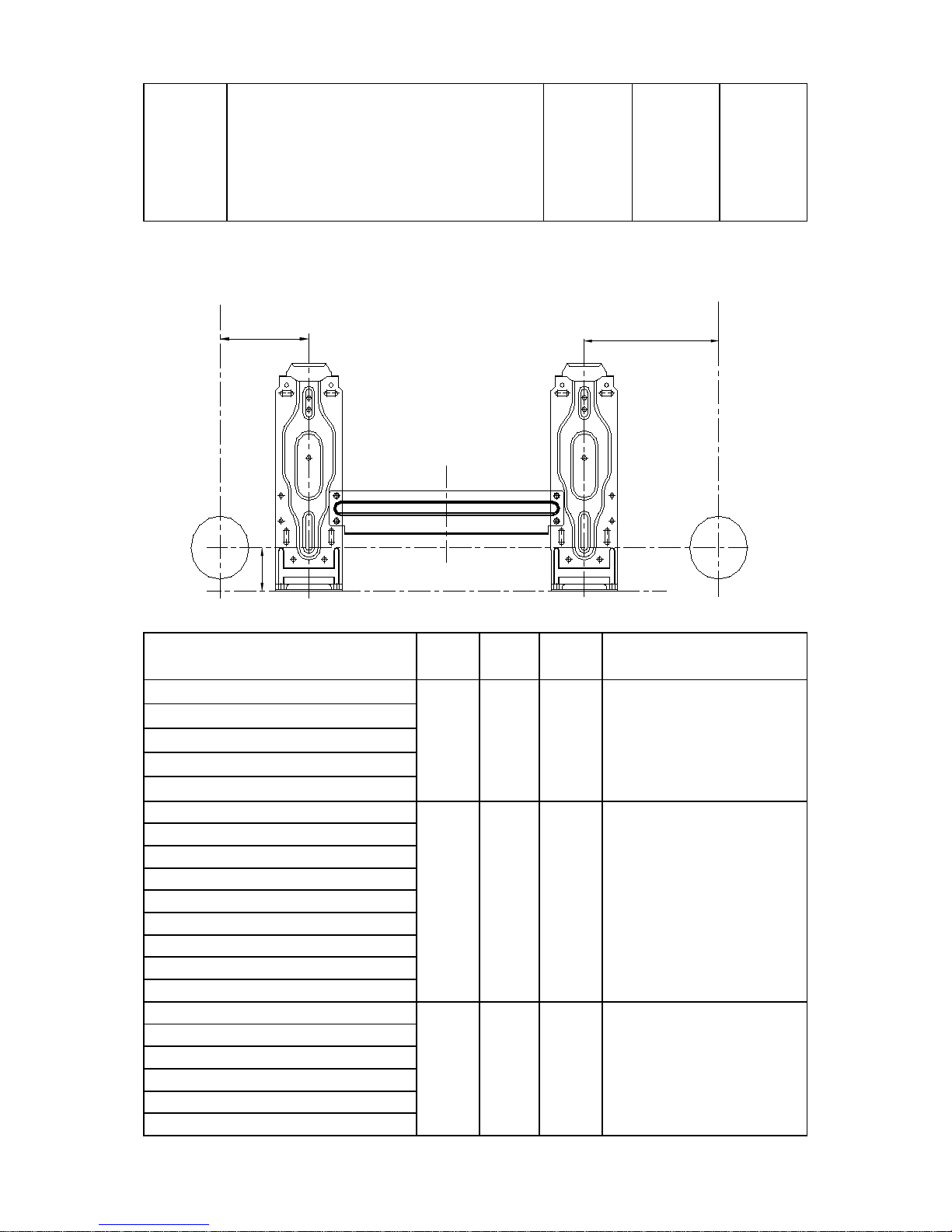
Model R(mm) L(mm) H(mm)
Dimension of installation
hole(mm)
MSR1-07HRN1-QC2(A)
111.5 100 45 Φ65
MSR1-09CRN1-QC2(A)
MSR1-12HRN1-QB6(A)
MSR1-07HRN1-QB6(A)
MSR1-09HRN1-QB6(A)
MSR1-09CRN1-QB8
83.5 100 45 Φ65
MSWR1-09CRN1-QB9
MSR1-12CRN1-QC2
MSR1-12HRN1-QC2
MSR1-12HRN1-QB8
MSR1-16HRN1-QB8(A)
MSR1-09HRN1-QC2(2T0032300791)
MSR1-12HRN1-QB6
MSR1-12CRN1-QB8
MSWR1-12CRN1-QB9
207 150 45 Φ65
MSR1-17CRN1-QB8
MSR1-18CRN1-QB8
MSR1-18HRN1-QB6
MSR1-16HRN1-QC2
MSR1-18HRN1-QC2
MSR1-21HRN1-QB4W
MSR1-21CRN1-QB8W
MSR1-21HRN1-QB8W
MSR1-24CRN1-QB8W
MSR1-24HRN1-QB8W
MSR1-24HRN1-QB4W
Page 12
10
MSWR1-18CRN1-QB9
139
100
45
Φ65
MSR1-21CRN1-QB8W
MSWR1-21CRN1-QB6
MSR1-21HRN1-QB4W
MSR1-21HRN1-QB8W
MSR1-24CRN1-QB8W
MSR1-24HRN1-QB4W
MSR1-24HRN1-QB8W
MSR1-09HRN1-QC2(2T0032300235)
136 60 45 Φ65
MSR1-07HRN1-QC2
Page 13
11
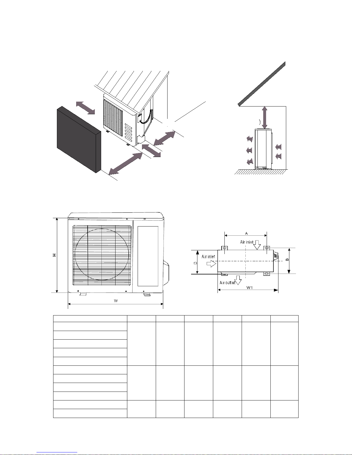
3.2 Outdoor Units
More than 30cm
More than 60cm
More than 70cm
More than 30cm
More than 60cm
(Service space
Fence or
obstacles
Model
W D H
W1 A B
MOK2-07HN1-QC2
685 260 430 742 460 276
MOK1-07HN1-QB6
MOK-09CN1-QB8
MOK-09HN1-QB6
MOK1-07HN1-QC2
MOA-09CN1-QC2
700 240 540 757 458 250
MOA1-09HN1-QC2
MOA-12HN1-QB6
MOA3-09HN1-QC2
MOB-12CN1-QC2
780 250 540 843 549 276
MOB2-12HN1-QC2
Page 14
12
MOB-12HRN1-QB8
MOB-16HN1-QC2
MOB-17CN1-QB8
MOB-12CN1-QB8
MOB1-18HN1-QB6
MOB-18HN1-QB6
MOC-18CN1-QB8
760 285 590 823 530 290
MOC-18HN1-QC2
MOC-21HN1-QB4W
MOP-21CN1-QB8W
820 330 595 870 523 340
MOP1-21HN1-QB8W
MOP-24HN1-QB4W
MOF-24CN1-QB8W
845 320 700 908 560 335
MOX-12CN1-QB9
MOX-18CN1-QB9
MOX-21CN1-QB6
MOF-21HN1-QB8W
MOF3-21HN1-QB8W
MOF-24CN1-QB8W
MOF2-24HN1-QB8W
MOW-09CN1-QB9: Dimension:450x390x353 (WDH) mm
Page 15
13
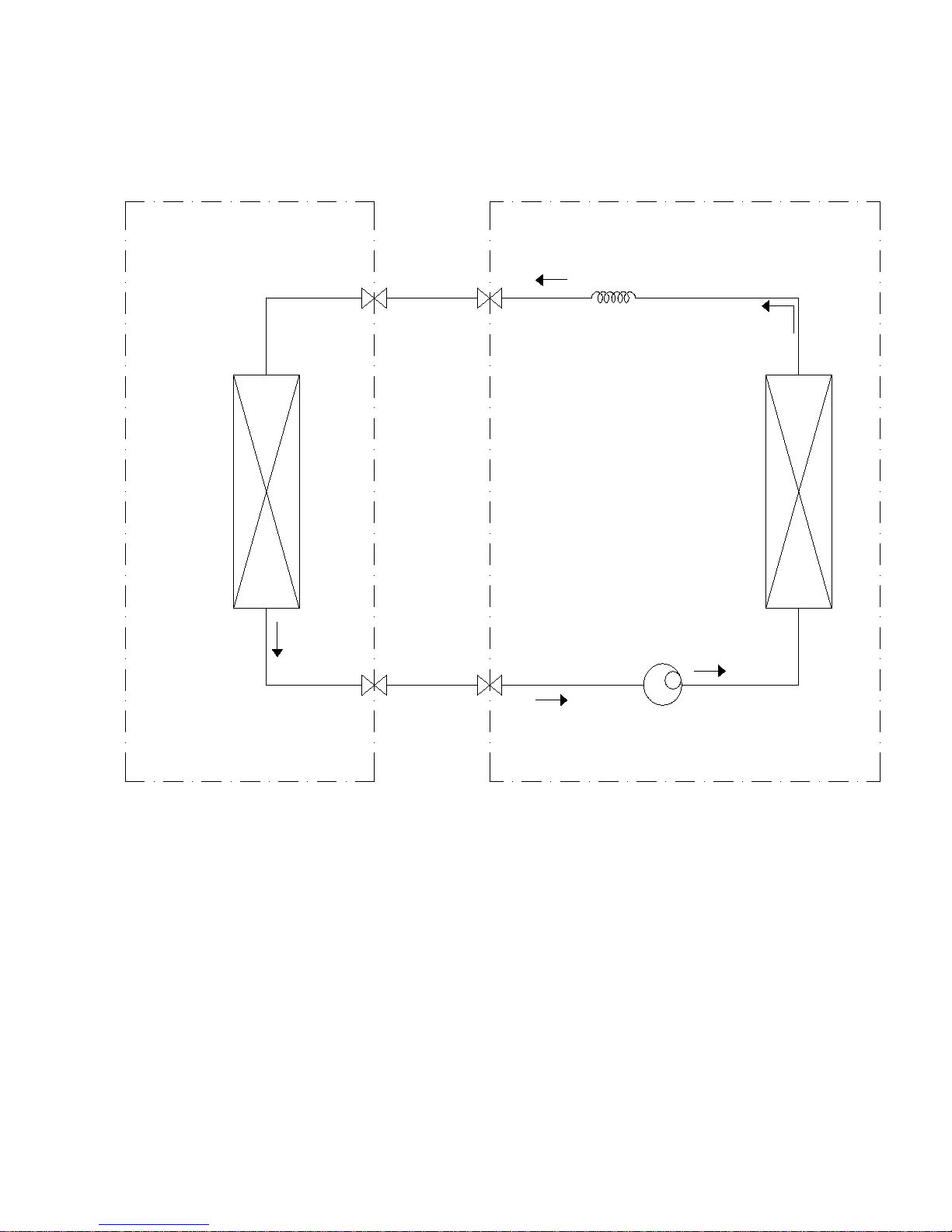
4. Refrigerant Cycle Diagram
For cooling only models:
INDOOR OUTDOOR
LIQUID SIDE
GAS SIDE
HEAT
EXCHANGE
(EVAPORATOR)
HEAT
EXCHANGE
(CONDENSER)
COMPRESSOR
CAPILIARY TUBE
Page 16
14
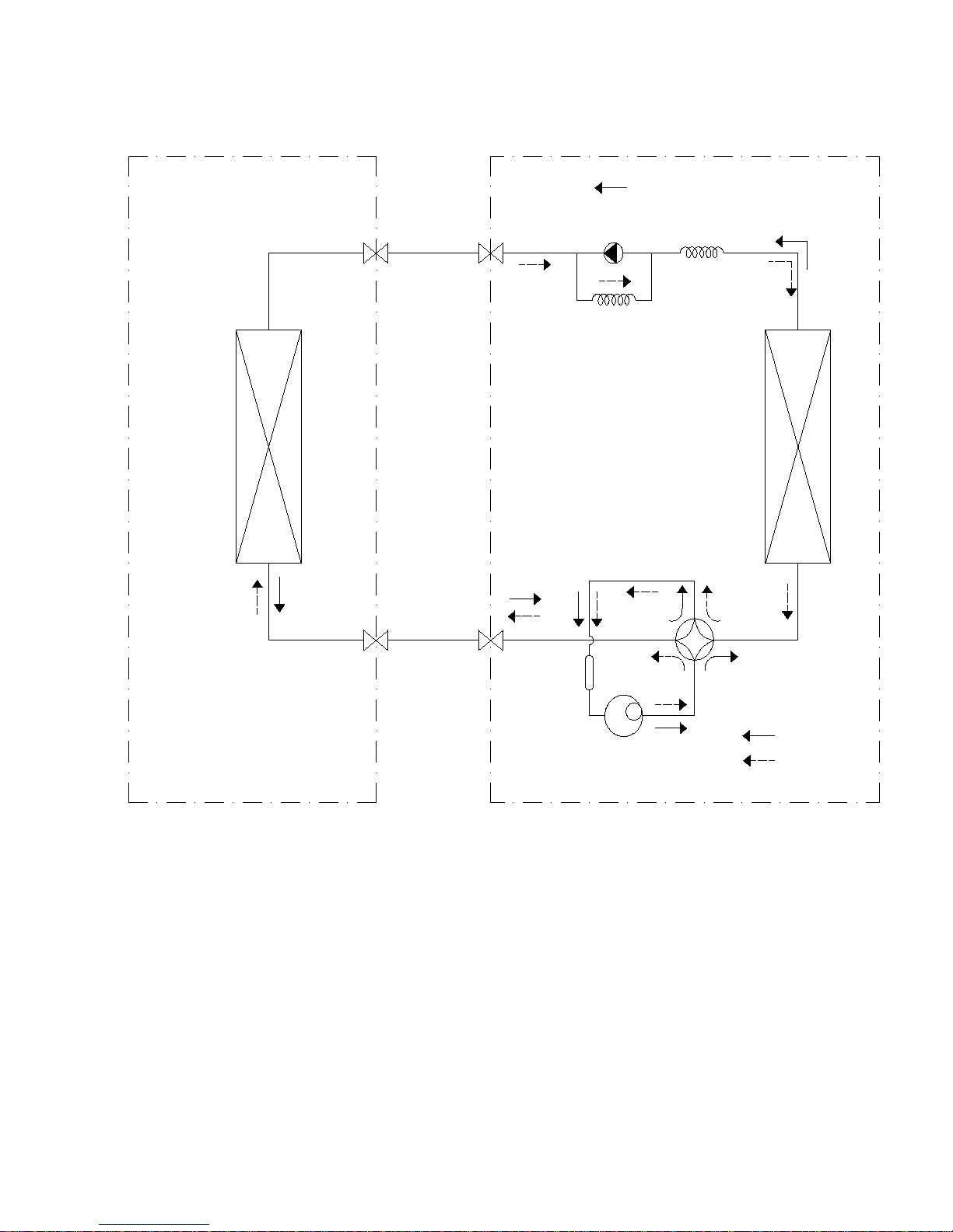
For heat pump models:
INDOOR OUTDOOR
LIQUID SIDE
GAS SIDE
HEAT
EXCHANGE
(EVAPORATOR)
HEAT
EXCHANGE
(CONDENSER)
COMPRESSOR
2-WAY VALVE
3-WAY VALVE
CHECK VALVE
(Heating Model only)
CAPILIARY TUBE
REVERSING VALVE
(Heating Model only)
COOLING
HEATING
ACCUMULATOR
Page 17
15
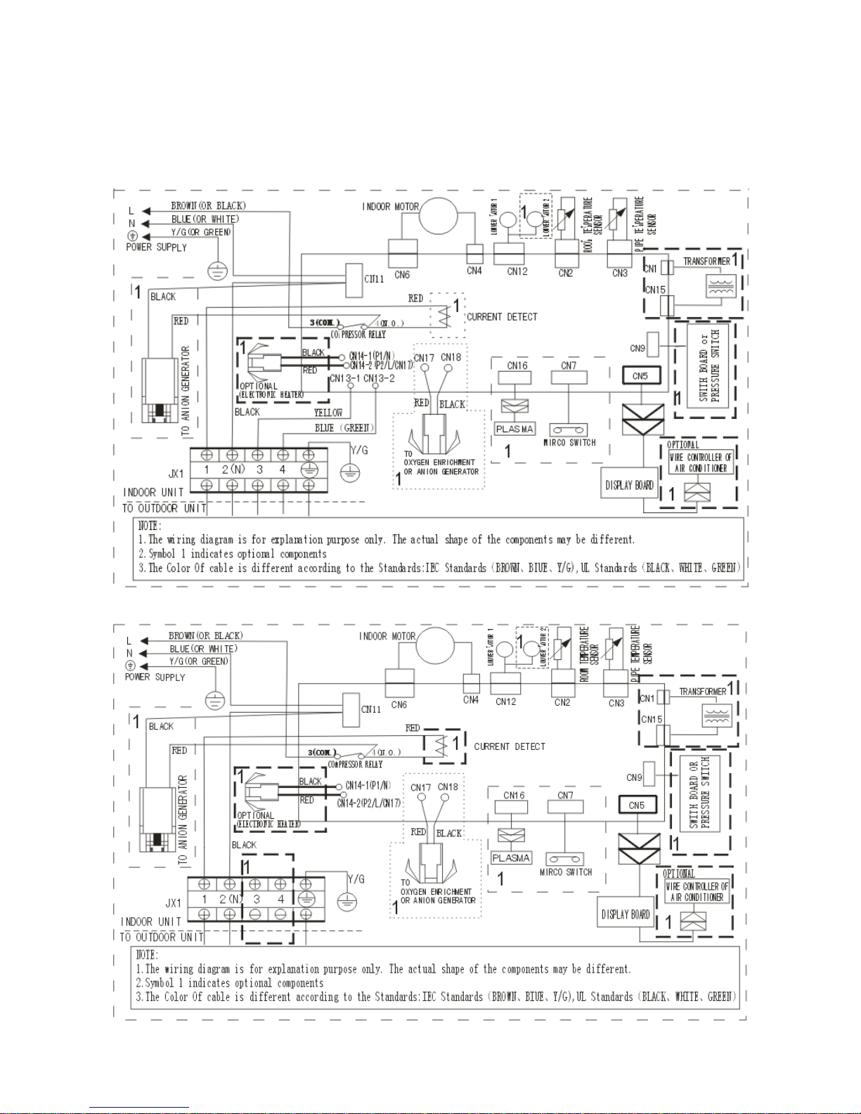
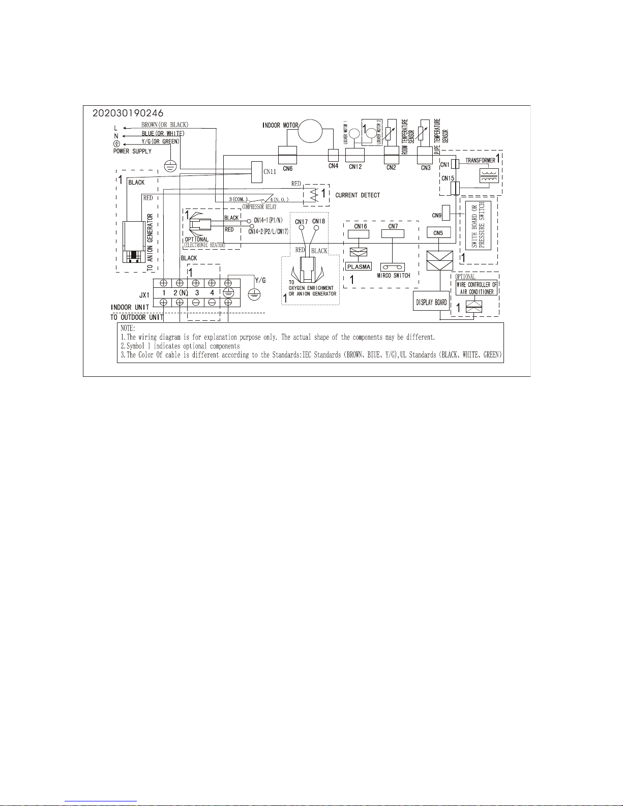
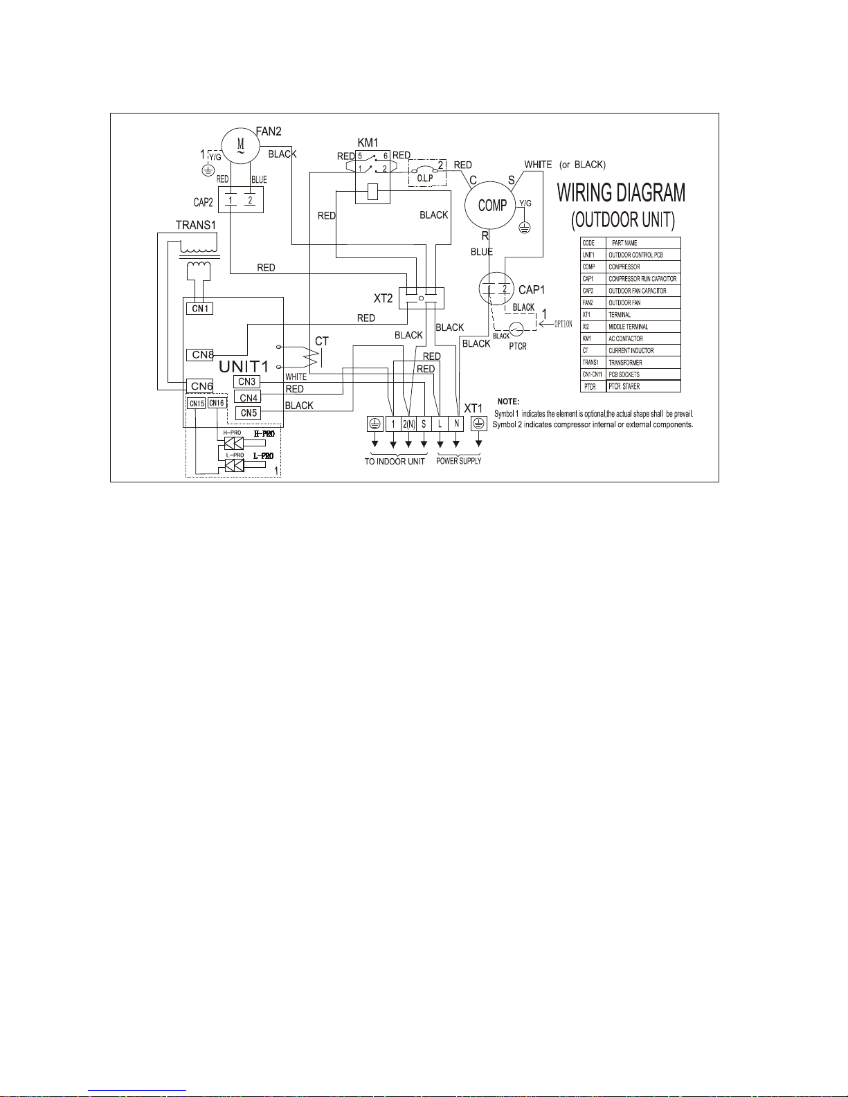
5. Wiring Diagram
5.1 Indoor Units
MSR1-07HRN1-QC2(A), MSR1-12HRN1-QB6(A), MSR1-12HRN1-QC2
MSR1-09CRN1-QC2(A), MSR1-12CRN1-QC2, MSR1-17CRN1-QB8
Page 18
16
MSR1-09CRN1-QB8, MSR1-12CRN1-QB8, MSWR1-09CRN1-QB9, MSWR1-12CRN1-QB9,
MSR1-18CRN1-QB8
Page 19
17
MSWR1-18CRN1-QB9, MSWR1-21CRN1-QB6
MSR1-24CRN1-QB8W,
Page 20

18
MSR1-21CRN1-QB8W, MSR1-21HRN1-QB8W
MSR1-07HRN1-QB6(A), MSR1-07HRN1-QC2, MSR1-09HRN1-QC2,MSR1-09HRN1-QB6(A),
MSR1-09HRN1-QC2, MSR1-12HRN1-QB8, MSR1-12HRN1-QB6, MSR1-16HRN1-QC2
MSR1-16HRN1-QB8(A), MSR1-18HRN1-QC2, MSR1-18HRN1-QB6
Page 21

19
MSR1-21HRN1-QB8W,MSR1-21HRN1-QB4W, MSR1-24CRN1-QB8W, MSR1-24HRN1-QB8W,
MSR1-24HRN1-QB4W
Page 22

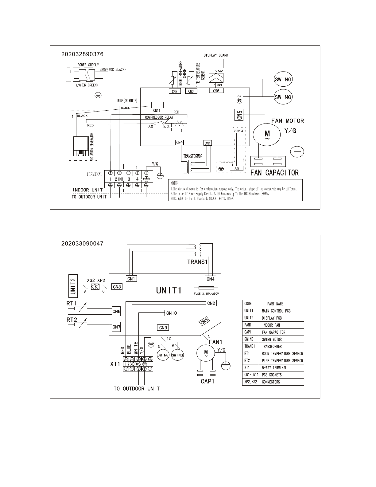
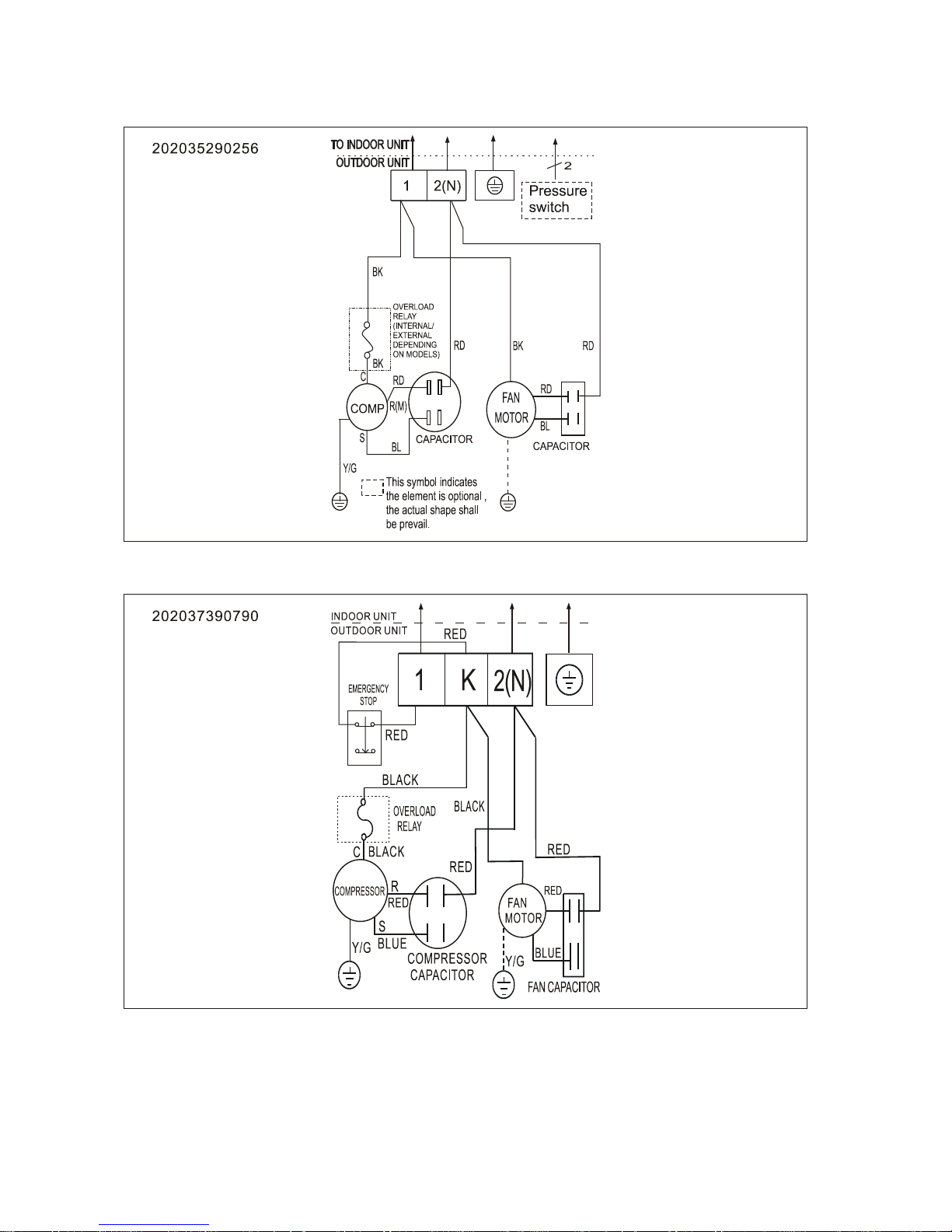
20
5.2 Outdoor Units
MOK2-07HN1-QC2, MOA-12HN1-QB6, MOB2-12HN1-QC2
Page 23

21
MOA-09CN1-QC2, MOB-12CN1-QC2
Page 24

22
MOB-17CN1-QB8
Page 25

23
MOC-18CN1-QB8
Page 26

24
MOP-21CN1-QB8W, MOP1-21HN1-QB8W
Page 27
25
MOK-09CN1-QB8, MOB-12CN1-QB8
MOW-09CN1-QB9
Page 28

26
MOX-12CN1-QB9, MOX-18CN1-QB9, MOX-21CN1-QB6
MOF-24CN1-QB8W
Page 29

27
MOC-18HN1-QC2
MOK1-07HN1-QC2,MOK1-07HN1-QB6, MOA1-09HN1-QC2, MOA3-09HN1-QC2,MOK-09HN1-QB6,
MOA-12HN1-QB6, MOB-12HRN1-QB8, MOB-16HN1-QC2,MOB1-18HN1-QB6, MOB-18HN1-QB6
Page 30

28
MOC-21HN1-QB4W,MOP-24HN1-QB4W
MOF-21HN1-QB8W
202038090201
Page 31

29
MOF3-21HN1-QB8W, MOF2-24HN1-QB8W
202038090672
Page 32
30
MOF-24CN1-QB8W
202035490277
Page 33

31
6. Installatio n details
6.1 Wrench torque sheet for installation
Outside diameter Torque
Additional
tightening torque
mm inch N.cm N.cm
Ф6.35 1/4
1500
(153kgf.cm)
1600
(163kgf.cm)
Ф9.52 3/8
2500
(255kgf.cm)
2600
(265kgf.cm)
Ф12.7 1/2
3500
(357kgf.cm)
3600
(367kgf.cm)
Ф15.9
5/8
4500
(459kgf.cm)
4700
(479kgf.cm)
6.2 Connecting the cables
The power cord of connect should be selected according to the following s pecifications sheet.
Rated current of appliance Nominal cross-sectional area (mm²)
>3 and ≤6 0.75
>6 and ≤10 1.0
>10 and ≤16 1.5
>16 and ≤25 2.5
The cable size and the current of the fuse or switch are determin ed by the maximum current indicated
on the nameplate which located on the side panel of the unit. Please refer to the nameplate before
selecting the cable, fuse and switch.
Page 34

32
6.3 Pipe length and the elevation
The pipe length and refrig er ant amount:
Model Connectiv e pipe length Air purging
Additional amount of
refrigerant
All Less than 5m Use vacuum pump -----------------7k,9k,12k,16k,17k,18k More than 5m Use vacuum pump (Pipe length – 5) × 20g/m
21k,24k More than 5m Use vacuum pump (Pipe length – 5) × 40g/m
Model
Standard
length
(m)
Max.
Elevation
B (m)
Max.
Length
A (m)
7k,9k,12k,16k,17k 5 8 20
18k,21k,24k 5 10 25
Caution:
The capacity test is based on the standard length an d the maximum permissive length is based on the
system reliability.
The oil trap should be inst all ed per 5-7 meters.
Page 35

33
6.4 Installation for the first time
Air and moisture in the refrigerant system have undesirable effects as below:
● Pressure in the system rises.
● Operating current rises.
● Cooling or heating efficiency drops.
● Moisture in the refrigerant circuit may freeze and block capillary tubing.
● Water may lead to corrosi on of parts in the refrigerant sys t em.
Therefore, the indoor units and the pipes between indoor and outdoor units must be leak tested
and evacuated to remove gas an d m oisture from the system.
Gas leak check (Soap water method):
Apply soap water or a liquid neutral detergent on the indoor unit connections or outdoor unit
connections by a soft brush to check for leakage of the connecting points of the piping. If bubbles
come out, the pipes have leakage.
1. Air pur ging with vacuum pump
1) Completely tighten the flare nuts of the indoor and outdoor units, confirm that both the 2-way and
3-way valves are set to the closed position
2) Connect the charge hose w it h t he push pin of handle lo to the 3-way valves gas service port..
3) Connect the charge hose of ha ndle hi connection to the vacuum pump.
4) Fully open the handle Lo of the ma ni fold valve.
5) Operate the vacuum pum p t o evacuate.
6) Make evacuation for 30 minutes and check whether the compound meter indicates -0.1Mpa. If
(Indoor unit)
(Liquid side)
(Gas side)
Vacuum
pump
Vacuum
pump
Lo
Hi
Handle Hi
Two-way valve
Close
Manifold valve
Compound meter
Pressure
gauge
-
0.1M
Pa
Handle Lo
Charge hose
Charge hose
(Outdoor unit)
Close
Three
-way valve
Page 36

34
the meter does not indicate -0.1Mpa after pumping 30 min ut es, it should be pumped 20 minutes more. If
the pressure can’t achi eve -0.1Mpa after pum ping 50 minutes, please check if there are some leakage
points.
Fully close the handle Lo valve of the manifold valve and stop the operation of the vacuum pump.
Confirm that the gauge needle does not move (approximately 5 minutes after turning off the vacuum
pump).
7) Turn the flare nut of the 3-way valves about 45° counterclo ckwise for 6 or 7seconds after the gas
coming out, then tighten the flare nut again. Ma ke sure the pressur e display in the pressur e indicator is
a little higher than the atmosph er e pr essure. Then remove the c har ge hose from the 3 way valve.
8) Fully open the 2 way valve and 3 way valve and securely tighten the cap of the 3 way valve.
2. Air purging by refrigerant
Procedure:
1). Confirm that both the 2-way and 3-way valves are set to the closed positi on.
2). Connect the charge set and a char ging cylinder to the service port of the 3-way valve.
3). Air purging
Open the valves on the charging c ylinder and the charge set. Purge the air by loosening the flare nut on
the 2-way valve approximately 45’ for 3 seconds the n closing it for 1 minute; repeat 3 times.
After purging the air, use a torque wrench to tight en the flare nut on the 2-way valve.
4). Check the gas leakage
Check the flare connections for gas leakage.
5). Discharge the refrigerant
Page 37

35
Close the valve on the charging cylinder and discharge the refrigerant by loosening the flare nut on the
2-way valve approximatel y 45’ until the gauge indicates 0.3 to 0.5 Mpa.
6). Disconnect the charg e set and th e char gi ng cyli nder, and set the 2-way and 3-way valves to t he ope n
position.
Be sure to use a hexagonal wrench to operate the valve stems.
7). Mount the valve stems nuts and the service port cap.
Be sure to use a torque wrench t o t ighten the service port cap to a torque 18N ·m.
Be sure to check the gas leakage.
3. Adding the refrigerant if the pipe length >5m
Procedure:
1). Connect the charge hose to t he c har ging cylinder , open t he 2-way valve and the 3-way valve.
Connect the charge hose w hich y ou disco nnecte d fr om the v acuu m pu mp to the v alve at the bot tom of
the cylinder. If the refrigerant is R410A, make the cylinder bottom up to ensure the liquid charge.
2). Purge the air from the charge hose
Open the valve at the bottom of the cylinder and press the check valve on the charge set to purge the
air (be careful of the liquid refrigerant).
3) Put the charging cylinder onto the electronic scale and record t he w eight.
4) Operate the air conditioner at t he c ool ing mode.
5) Open the valves (Low side) on the charge set and charge the system with l i qui d r efrigerant.
Electronic scale
Page 38

36
6).When the electronic scale displays the proper weight (refer to the table), disconnect the charge hose
from the 3-way valve’ s ser vice port immediately and turn off the air conditioner before disconnecting the
hose.
7). Mount the valve stem caps and the service port
Use torque wrench to tighten the service port cap to a torque of 18N.m.
Be sure to check for gas lea kage.
6.5 Adding the refrigera nt after running the system for many years
Procedure:
1). Connect the charge hose to t he 3-way service port, open the 2-way valv e and t he 3-way valve.
Connect the charge hose to the valve at the bottom of the cylinder. If the refrigerant is R410A, make
the cylinder bottom up to ensure liquid charge.
2). Purge the air from the charge hose
Open the valve at the bottom of the cylinder and press the check valve on the charge set to purge the
air (be careful of the liquid refrigerant).
3) Put the charging cylinder onto the electronic scale and record t he w eight.
4) Operate the air conditioner at t he c ool ing mode.
5) Open the valves (Low side) on the charge set and charge the system with l i qui d r efrigerant.
Electronic scale
Page 39

37
6).When the electronic scale displays the proper weight (refer to the gauge an d t he pressure of the low
side), disconnect the charge hose from the 3-way valve’ s ser vice port immediately and turn off the air
conditioner before disconnecting the hose.
7). Mount the valve stem caps and the service port
Use torque wrench to tighten the service port cap to a torque of 18N.m.
Be sure to check for gas lea kage.
6.6 Re-installation while the indoor unit need to be repaired
1. Collecting the refrigerant into the outdoor unit
Procedure
1). Confirm that both the 2-way and 3-way valves ar e set t o t he opened position.
Remove the valve stem caps and confirm that the valve stems are i n t he opened position.
Be sure to use a hexagonal wrench to operate the valve stems.
2). Connect the charge hose with the push pin of handle lo to the 3-way v alv es gas service port.
3). Air purging of the charge hose
Open the handle Lo valve of the ma ni fold valve slightly to purge air from the c harge hose for 5 seconds
and then close it quickly.
4). Set the 2-way valve to the close position.
Page 40

38
5). Operate the air conditi oner at t he cooling cycle and stop it when the gauge indi cat es 0.1MPa.
6). Set the 3-way valve to the closed position immediately
Do this quickly so that the gaug e ends up indicating 0.3 to 0.5Mpa.
Disconnect the charge set, and tighten the 2-way and 3-way valve’s stem nut s .
Use a torque wrench to tight en t he 3-way valves service port cap to a torque o f 18N.m.
Be sure to check for gas lea kage.
2. Air purgi ng by the refrigerant
Procedure:
1). Confirm that both the 2-way and 3-way valves are set to the closed position.
2). Connect the charge set and a char ging cylinder to the service port of the 3-way valve.
Leave the valve on the chargin g cylinder closed.
3). Air purging
Open the valves on the charging cylinder and the charge set. Purge the air by loosening the flare nut on
the 2-way valve approximately 45’ for 3 seconds the n closing it for 1 minute; repeat 3 times.
After purging the air, use a torque wrench to tight en the flare nut on the 2-way valve.
4). Check the gas leakage
Check the flare connections for gas leakage.
5). Discharge the refrigerant
Page 41

39
Close the valve on the charging cylinder and discharge the refrigerant by loosening the flare nut on the
2-way valve approximatel y 45’ until the gauge indicates 0.3 to 0.5 Mpa.
6). Disconnect the char ge set and th e char ging cy lin der, and set the 2-way and 3-way valves to t he open
position.
Be sure to use a hexagonal wrench to operate the valve stems.
7). Mount the valve stems nuts and the service port cap.
Be sure to use a torque wrench to tighten the service port cap to a torque 18 N .m.
Be sure to check the gas leakage.
6.7 Re-installation while the outdoor unit need to be repaired
1. Evacuation for the whole sy stem
Procedure:
1). Confirm that both the 2-w ay and 3-way valves are set to the opened pos it i on.
2). Connect the vacuum pump t o 3-way valve’s service port.
3). Evacuation for approxi mately one hour
Confirm that the compound meter ind icate s -0.1Mpa.
4). Close the valve (Low side) on the charge set, turn off the vacuum pump, and confirm that the gauge
needle does not move (appr oximately 5 minutes after tur ning off the vacuum pump).
Page 42

40
5). Disconnect the charge hose from the vacuum pump.
2. Refrigerant charging
Procedure:
1). Connect the charge hose to t he c har ging cylinder , open t he 2-way valve and the 3-way valve.
Connect the charge hose w hich y ou disco nnecte d fr om the v acuu m pu mp to the v alve at the bot tom of
the cylinder. If the refrigerant is R410A, make the cylinder bottom up to ensure liquid c har ge.
2). Purge the air from the charge hose
Open the valve at the bottom of the cylinder and press the check valve on the charge set to purge the
air (be careful of the liquid refrigerant).
3) Put the charging cylinder onto the electronic scale and record t he w eight.
4). Open the valves (Low side) on the charge set and charge the syste m with liquid refrigerant.
If the system cannot be char ge w ith the specified amount of refrigerant, or can be charged with a little at
a time (approximately 150g each t ime) , operating the air conditioner in t he cooling cycle; however, one
time is not sufficient, w ait approximately 1 minute and then repeat the procedure.
5).When the electronic scale displays the proper weight, disconnect t he charge hose from the 3-way
valve’s service port immediately.
If the system has been charged with liquid refrigerant w hile operating t he air conditioner, turn off the air
conditioner before disconnecting the hose.
Electronic scale
Page 43

41
6). Mounted the valve stem cap s and the service port
Use torque wrench to tight en t he ser vice port cap to a torque of 18N.m.
Be sure to check for gas lea kage.
7. Operation characteristics
CAUTION:
1. If air conditioner is used beyond the above conditions, the certain protections may action.
2. Room relative humidity should be less than 80%. If the air conditioner operates in excess of this
value, the surface of the air conditioner may attract condensation water. In this case, please set the
vertical air louver to its maximum angle (vertically to the floor) , and s et t he f an t o high speed.
Page 44

42
8. Electronic function
8.1 Abbreviation
T1: Indoor ambient temperatur e
T2: Coil temperature of indoor heat exc hanger
T3: Coil temperature of out door heat exchanger
T4: Outdoor ambient temp er ature
T5: Compressor discharge tem per ature
8.2 Display function
8.2.1 Icon explanation on indoor disp lay boar d.
Auto indicator:
This indicator illuminates when the air conditioner is in AUTO operation.
PRE.-DEF. Indicator(only for heat pump models)
This indicator illuminates when the air conditioner starts defrosting automatically or
when the warm air control feature is activated in heating mode.
OPERATION indicator:
This indicator illuminates when the air conditioner is running.
Timer indicat or :
This indicator illuminates when TIMER is set ON/OFF
Page 45

43
8.3 Main Protection
8.3.1 Time delay at restart for compressor .
8.3.2 Fan Speed is out of control. (only for 7k,9k,12,16k,17k,18k(except MSWR1-18CRN1-QB9)
models)
----When Indoor Fan Speed keeps too low or too high for certain time, the unit will stop and the LED
will display the failure
8.3.3 Current protection
I3SEC
I5MIN
A
B
C
Resume
IFAN
IRESTORE
A zone: The current exceeds I
3SEC
for 5 seconds(3 seconds for 21k model), the compressor and
outdoor fan will shut off.
B zone: The current exceeds I
5min
for 5 minutes, the compressor and outdoor fan will shut off.
C zone: The current exceeds I
FAN
, the outdoor fan will shut off if AC is in heating mode. If AC is in
cooling mode, the indoor fan w il l run at low speed.
8.3.4 Zero crossi ng detection error protection (only for 7k, 9k, 12k,16k, 17k,18k
(MSWR1-18CRN1-QB9) models)
If AC can not detect zero crossing signal for 4 minutes or the zero crossing signal time interval is not
correct, the unit will stop and the LED will display the failure. The correct zero crossing signal time
interval should be betwee n 6-13ms.
8.3.5 Indoor / outdoor units communication pr ot ection(only for MSR1-21CRN1-QB8W,
MSR1-21HRN1-QB8W, MSR1-21HRN1-QB4W, MSR1-24CRN1-QB8W,MSR1-24HRN1-QB4W,
MSR1-24HRN1-QB8W models)
If the indoor units can not receive the fee dback signal from the outdoor units for 2 minut es , the AC will
stop and display the failur e.
Page 46

44
8.4 Operation Modes and Functions
8.4.1 Fan mode
(1) Outdoor fan and compressor stop.
(2) Temperature setting function is disabled, and no setting temperature is displayed.
(3) Indoor fan can be set to high/med/low / auto.
(4) The louver operates same as in cooling mode.
(5) Auto fa n:
For 7k,9k,12k,16k,17k,18k, MSWR1-21CRN1-QB6 models:
For MSR1-21HRN1-QB4W, MSR1-21CRN1-QB8W, MSR1-21HRN1-QB8W, MSR1-24CRN1-QB8W,
MSR1-24HRN1-QB8W,MSR1-24HRN1-QB4W,models:
8.4.2 Cooling Mode
8.4.2.1 Compressor running rules:
Once the compressor star ts up, it will follow the below rules:
When indoor room temp.T1 is lower than Tn, the compr ess or and outdoor fan will shut off. When T1 is
higher than Tm, the compressor and out door fan will start up.
Page 47

45
Tm=Ts+1, Tn=Ts.
Tm=Ts, Tn=Ts-2 for MSWR1-18CRN1-QB9 and MSWR1-21CRN1-QB6 models.
8.4.2.2 Outdoor fan r unning rules:
The On-off outdoor units have single fan speed. The outdoor fan will run following the compressor
except when AC is in evaporator high temp. protection in heating mode ,condenser high temp.
protection in cooling mode, defrosting mode and the current protection.
8.4.2.3 Indoor fan running rules
In cooling mode, indoor fan runs all the time and the speed can be selected as high, medium, low and
auto.
The auto fan:
8.4.2.4 Evaporator low t em perature T2 protection.
When the evaporator coil temp.T2 keeps lower than TE5 for 5 minutes(4 minutes for 21k model), the
compressor and outd oor f an w il l shut off.
When T2 is higher than TE6, the compressor and outdoor fan will restart up.
Page 48

46
8.4.2.5 Condenser high temperat ure T3 protection(only for 21k,24k heat pump models)
T3
TE10
Off
On
TE11
When T3≥TE10, the compressor will shut off. When T3<TE11,the compressor will restart.
8.4.3 Heating Mode
8.4.3.1 Compre ssor running rules:
For 21k,24k models, every time the compressors start up, they will keep running for △t
minutes(protections are active) and then follow the below rules. (While △t=4.)
For other models, they will follow the below rules once the compressors start up:
When indoor room tem p.T1 is higher than Tj, th e compressor and outdoor fan will shut of f. When T1 is
lower than Tk, the compr essor and outdoor fan will start up.
Tj=Ts+Tc
Tk=Ts+Tc-1.
8.4.3.2 Out door fan running rules:
The outdoor units have single fan speed. The outdoor fan will run following the compressor except
when AC is in evaporator high temp. protection in heating mode , condenser high temp. protection in
cooling mode ,defrosting mode and the current protection.
8.4.3.3 Indoor fan running rules:
For 21k,24k models, when the compressor is off because off the room temperature rising or the
protection, the indoor fan w ill ru n as below rule:
Page 49

47
For21k,24k models:
While TE14=32℃.
For all the models, when the compressor is on, the indoor fan can be set to high/med/ low/aut o. And the
anti-cold wind function has the priority.
Anti-cold wind function:
When the evaporator coil temp.T2 is gettin g higher,
T2>TE2, the indoor fan wi ll run at s et t i ng s peed.
TE1<T2<TE2, the indoor fan w il l run at low speed.
When T2 is getting lower,
TE4<T2<TE3,the indoor f an w il l run at low speed.
T2<TE4, the indoor fan will shut off.
Auto fan action :
When T1-Ts>2℃, the indoor fan will run at low spe ed.
Page 50

48
When T1-Ts≤0℃, the indoor fan will run at medium speed.
8.4.3.4 High evaporator coil temp.T2 prot ection:
For 21k,24k models:
For other models:
8.4.3.5 Defrosting mode:
For 7k,12k, MSR1-09HRN1-QC2, MSR1-09HRN1-QB6(A)models(except MSR1-07HRN1-QB6(A))
MSR1-16HRN1-QC2,MSR1-18HRN1-QB6 models:
Condition of defrosting:
AC will enter defrosting mode if any of the following items is satisfied.
(1) Both A an d B are s atisfied
A: The compressor keeps running for 40 minutes.
B: The evaporator coil temp.T2-Indoor room temp.T1 meets the below table.
TE7
Compressor and Outdoor fan on
T2
TE9
℃
TE8
Outdoor fan off
Compressor off
Page 51

49
℃
T2-T1
High speed
<TH
DEFROST
Medium speed
<TM
DEFROST
Low speed
<TL
DEFROST
Breeze/off No need to compare the T2 and T1
(2) After the last defrosting, the time that the outdoor fan is off but the compressor is on in high T2
protection cumulates up to 90 m in ut es .
Condition of ending defrosting:
If any one of the following items is satisfied, the defrosting will terminate and the machine will turn to
normal heating mode.
(1) The defrosting time is reached to the setting value.
(2) The compres sor cur r ent reaches or exceeds I
DEFROST
for 7 seconds.
Defrosting action
:
About the setting defrosting time:
(1) Condition 1 of defrosting;
If case B happens before case A and lasts till case A happens, the setting defrosting time is 10 minutes.
Otherwise the defrosting t ime is 7.5 minutes.
(2) Condition 2 of defrosting.
The defrosting time is 10 m inutes.
(3) No matter what c onditio n of defrost ing is, if the d efro sting time keeps 7.5 minutes for 3 times, it w ill
be 10 minutes in the 4
th
defrosting.
Page 52

50
For 21k,24k models:
1) Defrosting condition:
AC will enter defrosting mode if any of the following items is satisfied.
(1) When T3<TC1℃, if th e compressor keeps ru nning ov er 40 minut es and T3<TC3℃ for 3 minutes.
(2) After the last defrosting, the time that the outdoor fan is off but the compressor is on in high T2
protection cumulates up to 90 m in ut es .
2) Condition of ending defrosting:
If any one of the following items is satisfied, the defrosting will terminate and the machine will turn to
normal heating mode.
(1)T3 rises to be higher than TC2.
(2)The machine has run for 10 minut es in d efrosting.
3) Defrosting action:
For MSR1-16HRN1-QB8(A),MSR1-18HRN1-QC2, MSR1-07HRN1-QB6(A) models:
Condition of defrosting:
If any one of following items is sat i sfied, defrosting will start.
Condition 1: Both the following conditions are satisfied:
A: If the working time of the compressor accumulates to 42 min and one continuous
working time is more than 330s.
B: Check the temperature difference between T2 and T1
℃
Fan speed
T2-T1 Note
High
<
TH
DEFROST
If indoor fan is in high speed and T2-T1< TH
DEFROST
, start defrosting
Medium
<
TM
DEFROST
If indoor fan is in medium speed and T2-T1< TM
DEFROST
, start defrosting
Low
<TL
DEFROST
If indoor fan is in low speed and T2-T1< TL
DEFROST
, start defrosting
Page 53

51
Breeze or stop / If indoor fan is breezing or stopped, start defrosting
Condition 2: If the accumulated time of outdoor f an stopped but the compressor keep working due to
evaporator high temperat ur e protection mode reaches 90 min fro m the end of last defrosting mode.
Condition of defrosting stop:
If any one of following conditions occurs, the defrosting will finish and the machine will turn to normal
heating mode.
Condition 1: Reached the defrosting time.
Condition 2: The current of compressor is more than I
defrost
continuously more than 7s. The value of
I
defrost
is depending on the exactly mach in e.
Defrosting actions:
During the defrosting mod e, if the machine stopped or transferred to other m ode, the defrosting mode
will stop, and all the defrost ing conditions will be cleared.
8.4.4 Auto-mode
The machine will choose cooling, heating or fan-only mode according to ΔT (ΔT =T1-Ts).
For MSR1-07HRN1-QC2,MSR1-07HRN1-QC2(A), MSR1-09CRN1-QC2(A), MSR1-09CRN1-QB8,
MSWR1-09CRN1-QB9,MSR1-09HRN1-QC2,MSR1-09HRN1-QB6(A),MSR1-12CRN1-QC2,MSR1-12
CRN1-QB8, MSR1-12HRN1-QB8,MSWR1-12CRN1-QB9,MSR1-12HRN1-QB6(A),
MSR1-12HRN1-QC2, MSR1-16HRN1-QC2, MSR1-17CRN1-QB8, MSR1-18CRN1-QB8,
MSR1-18HRN1-QC2, MSR1-07HRN1-QB6(A),
MSR1-16HRN1-QB8(A), MSR1-12HRN1-QB6,
MSR1-18HRN1-QB6 models:
Page 54

52
ΔT=T1-Ts Running mode
ΔT>2℃
Cooling
-1≤ΔT≤2℃ Fan-only
ΔT<-1 ℃ Heating(for cooling only models,
they will
run at fan-only mode)
For MSWR1-18CRN1-QB9, MSWR1-21CRN1-QB6 models:
ΔT=T1-Ts Running mode
ΔT>2℃
Cooling
-3≤ΔT≤2℃
Fan-only
ΔT<-3℃
Heating(for cooling only models,
they will
run at fan-only mode)
For MSR1-21CRN1-QB8W, MSR1-21HRN1-QB8W, MSR1-21HRN1-QB4W, MSR1-24CRN1-QB8W ,
MSR1-24HRN1-QB8W,MSR1-24HRN1-QB4W models:
ΔT=T1-Ts Running mode
ΔT>2 ℃
Cooling
-1<ΔT ≤2℃ Fan-only
ΔT≤-1 ℃ Heating(for cooling only models,
they will
run at fan-only mode)
AC will run in auto mode in the below cases:
(1) Press the forced auto button.
(2) If AC is off, it will run in auto mode when timer on function is active.
(3) After setting the mode, AC will run in auto mode if the compressor keeps not running for 15
minutes(20 minutes for MSWR1-18CRN1-QB9 and MSWR1-21CRN1-QB6)
8.4.5 Drying mode
For 7k,9k,12k,16k,17k,18k models:
8.4.5.1 The indoor fan w ill run fol lowing t he c ompres sor .If the compressor is on, the indoor f an wi ll run
at low speed .If the compressor i s off, the indoor fan will run at breez e.
Running rules:
No
Condition
Indoor fan
Compressor and outdoor fan
Page 55

53
1 T1 ≥ TS+2
Low
Breeze
ON 6 minutes
OFF 4 minutes
2
TS ≤T1<TS+2
Low
Breeze
ON 5 minutes
OFF 5 minutes
3
T1<TS
Low
Breeze
ON 4 minutes
OFF 6 minutes
8.4.5.2 In drying mode, if room temperature is lower t han 10 ℃, the indoor fan will run at breeze w hile
the compressor and out door fan will stop and not resume unti l room temperature exceeds 13 ℃.
8.4.5.3 System protection is activ e in t his m ode.
For 21k,24k models:
8.4.5.4 The indoor fan will keep running at low speed.
8.4.5.5 The outdoor fan, compressor and all the protections are the s ame with cooling mode.
8.4.6 Forced operation funct i on
Press the touch button continually, the AC will run as below sequ ence:
Forced auto →Forced cooling→ Off
Forced cooling mode:
The compressor and outdoor fan keep running and the indoor fan runs at low speed. After running for
30 minutes, AC will turn to drying mode(AC will turn to auto mode for 21k,24k models) with 24℃
setting temperature.
Forced auto mode:
The action of forced auto mode is the same as normal auto mode with 24℃ setting temperature.
When AC receives signals, such as switch on, switch off, timer on, t imer off, mode setting, fan
speed setting ,sleeping mode sett ing, follow me setting, it will quit the forced operation.
The forced operation function can not be mem or ized if power off.
8.4.7 Timer function
8.4.7.1 Timing range is 24 hours.
8.4.7.2 Timer on. The mac hine will turn on automatically when reaching the setting time.
8.4.7.3 Timer off. The machine will turn off automatically w hen r eaching the setting time.
Page 56

54
8.4.7.4 Timer on/off. The machine will turn on automatically when reaching the setting “on” time, and
then turn off automat ically when reaching the setting “off” time.
8.4.7.5 Timer off/on. The machine will turn off automatically when reaching the setting “off” time, and
then turn on automatically w hen r eaching the setting “on” time.
8.4.7.6 For 7k,9k,12k,16k,17k,18k models, the timer function will not change the AC current operation
mode. Suppose users set the “timer off” function and AC is off now, the AC will keep the current
running mode and then turn off when reaching the setting ti m e. For 21k,24k models, the timer function
will change the AC current operation mode. Suppose users set the “timer off” function and AC is off
now, t he AC will turn on firstly and then turn off when reaching the sett ing time.
8.4.7.7 The setting time is r elat iv e t ime.
8.4.8 Sleep function mode
8.4.8.1 Operation time in sleep mode is 7 hours. Af t er 7 hour s, the AC quits this mode and turns off.
8.4.8.2.Operation process in sleep mode is a s fo ll ow:
After pressing ECONOM IC or SLEEP button on cont r oller, the machine will turn into sleep mode.
When cooling, the setting temperature rises 1 ℃
(be lower th
setting temperature stops rising and indoor fan is fixed as low speed.
When heating, the setting temperature decreases 1 ℃
(be higher than 17℃) e
ur, 2 hours
later the setting temperature stops rising and indoor fan is fixed as low speed.(Anti-cold wind function
has the priority).
8.4.8.3 Timer s et ting is available.
8.4.8.4 When user uses timer off function in sleep mode(or sleep function in timer off mode), if the
timing is less than 7 hours, sleep function wil l be cancelled wh en reachi ng the sett ing time. I f the timing
is more than 7 hours, the mach ine w i ll n ot s t op unt i l reaches the setting time in sleep mode.
8.4.9 Auto-Restart function
The indoor unit is equipped with auto-restart function, which is carried out through an auto-restart
module. In case of a sudden power failure, the module memorizes the setting conditions before the
power failure. The unit will resume the previous operation setting (not including Swing function)
automatically after 3 m inutes when power returns.
If the memorization condition is forced cooling mode, the unit will run in cooling mode for 30 minutes
and then turn to drying mode(auto mode for 21k,24k models)as 24 ℃ s e ttin g tem p .
Page 57

55
Page 58

56
9. Troubleshooting
9.1 Indoor unit error display
For MSR1-21CRN1-QB8W, MSR1-24CRN1-QB8W models:
Operation
lamp
Timer
lamp
Auto lamp Failure
☆ ☆ ☆ Over current protection occur s 4 times.
☆ X X The T2 sensor is open circuit or short circuit
X ☆ X The T1 sensor is open circuit or short circuit
☆ ☆ X EEPROM error
X X ☆ Indoor / outdoor units communication error
For MSR1-21HRN1-QB8W, MSR1-21HRN1-QB4W, MSR1-24HRN1-QB4W, MSR1-24HRN1-QB8W
models:
Operation
lamp
Timer
lamp
Defrosting
lamp
Auto
lamp
Failure
☆ ☆ ☆ X Over current protection occur s 4 times.
☆ X X X The T2 sensor is open cir cuit or shor t circuit
X ☆ X X The T1 sensor is open circuit or short circuit
X X ☆ X The T3 sensor is open circuit or short circuit
☆ ☆ X X EEPROM error
X X X ☆ Indoor / outdoor units communicat io n er r or
O(light) X(off) ☆(flash)
Page 59

57
For MSWR1-18CRN1-QB9 and MSWR1-21CRN1-QB6 models:
Error
Failure
E1
EEPROM error
E5
The T1 sensor is open cir cuit or shor t circuit
E6
The T2 sensor is open cir cuit or shor t circuit
For MSR1-16HRN1-QB8(A), MSR1-18HRN1-QC2, MSR1-07HRN1-QB6(A) models:
Display LED STATUS
E1 EEPROM error
E2 Zero-Crossing Error
E3 Indoor fan speed has been out of control
E4 Over current protection of the compressor occurs 4 times
E5 Open circuit or short circuit of room temperature sensor
E6 Evaporator temperature sensor open circuit or short circuit
For other models:
Operation lamp
Timer lamp
Failure
☆
X
Indoor fan speed has been out of co nt r ol
☆
O
The T1 or T2 sens or is open circuit or short circuit
X
☆
Over current protection occurs 4 times(except
MSR1-09HRN1-QC2,MSR1-12HRN1-QB8,
MSR1-16HRN1-QC2)
O
☆
EEPROM error
☆ ☆
Zero crossing detection err or
Page 60
58
9.2 Diagnosis and Solution
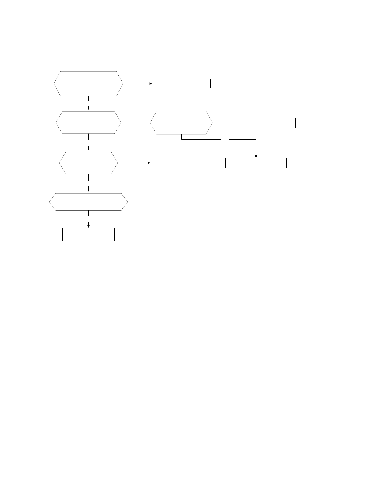
9.2.1 Indoor fan speed o ut of control diagnosis and solution
Shut off the power supply
and turn it on 5 seconds
later.Is it still displaying
the error code?
Shut off the power
supply, rotate the cross
fan by hand. Does it
rotate properly?
The unit operates normally.
Disassembly the
connection between
fan and motor, check if
the bearing is normal?
Replace the bearing.
Check the wires of
fan motor. Are all the
connections good?
No
Yes
No No
Replace indoor fan motor.
Yes
Correct the connections.
No
No
Yes
Yes
Check the resistance value of
indoor fan motor, is it normal?
Replace indoor PCB.
Yes
Page 61
59
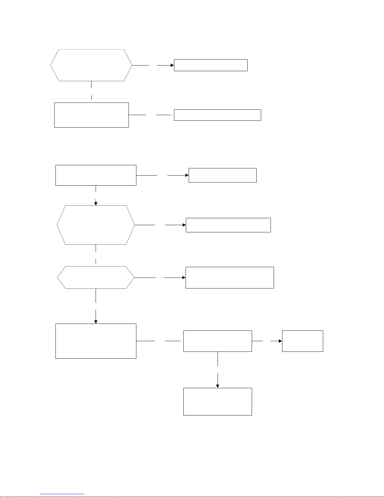
9.2.2 Open circuit or short circuit of temperature sensor diagnosis and solution
Check the connections
between temperature
sensor and PCB. Are
the connections good?
Correct the connections.
No
Yes
Yes Replace indoor or outdoor PCB.
Replace the sensor and
check if the problem
happen again?
9.2.3 Over current protection occur s 4 t i m es diagnosis and solution
No
Correct the operation condition.
Check if the voltage of the
power supply is too low
?
Yes
Repair the power supply.
Is the outdoor
operation temperature
too high? Does the
outdoor unit has bad
air circulation?
Yes
No
Check if the outdoor
fan can run properly?
No
Correct the connection of fan
motor or replace the fan motor.
Yes
Yes
Check if the compressor
is normal running
No
Replace the
compressor
Yes
Replace the capillary.
Evacuate the system
and recharge refrigerant.
Disconnect with the power
and replace the main PCB.
Turn on the units and check
if the problem remains
Page 62

60
9.2.4 EEPROM parameter error diagnosis and solution
Is the EEPROM chip
plugged in PCB well?
Yes
No
Yes
Correct the connection.
Replace the indoor PCB.
Shut off the power supply and
turn it on 5 seconds later. Is it
still displaying the error code?
9.2.5 Zero crossing detection error diagnosi s and solution
Check if the connections and
power supply is normal?
Correct the connections. Turn on the
unit when the power supply is good.
No
Yes
Indoor PCB is defective.
Replace indoor PCB.
Page 63

61
9.2.6 Indoor / outdoor units communication error diagnosis and solution
Yes
Yes
Is -24V<Vs<+24V?
(Vs is the voltage between S
and N of outdoor unit.)
Yes
Power off, then turn on the unit 5 seconds
later(reconnect the power wire).Is the error
still displaying after several minutes?
No
Yes
Change the outdoor Main PCB.
Power on. Is the error extinguished?
Check all the wirings between indoor and
outdoor, indoor PCB and outdoor PCB
following the wiring diagram. Are all the
wirings connected correctly?
Is the wiring to the indoor PCB
connected correctly?
Change the indoor PCB.
Yes
Change the outdoor main PCB.
No
Is the wiring to the outdoor PCB
connected correctly?
Power on. Is the error extinguished?
Change the outdoor main PCB.
No
 Loading...