

Page 1
Operation
Maintenance Manual
MKA/MKB/MKC/MKT/MKT2
200CFM~1500CFM
(50Hz/60Hz)
Fan Coil Unit
Cassette and Ceiling Concealed Series
Page 2

Content MCAC-KTSM-2007-2
i Content
Introduction…………………………………………………………………………………………..1
Part 1 General Information………………………………………………………………………...2
Part 2 Indoor Unit……………………………………………………………………......................7
Part 3 Installation………………………………….……………………………........................127
Page 3

MCAC-KTSM-2007-2 Introduction
Introduction 1
Introduction
Fan coil unit is a kind of compound device which assemble fan and surface-type coil heating-exchanger
together. Fan coil with fresh air supply system is a main type of center air-conditioner system, so it is an
important component of AC devices. Fan coil has horizontal type, vertical type, etc. A cooling (heating)
supply system usually consists of fan coil terminals and chilled water system (heated water system).
Midea
®
commercial AC fan coil is designed and manufactured on the base of advanced technology, and
utilize qualified galvanized iron as material. Due to its supper-thin design, it has such advantages: beautiful
outlook, space saving, easy installation, etc. And the most obvious advantage is that it can decrease the
outlet air Temp-difference as low as possible to make room more comfortable, as well as don’t decrease
cooling capacity output. For the large air flow volume design, it can increase room ventilation frequency,
supply more flesh air, and balance room temperature distribution. Benefiting from adoption of advanced
material and technology, it can effectively decrease the running noise and keep running smoothly. With the
advantages above, it can be widely applied in market, hospital, office building, hotel airport, etc.
Page 4

General information MCAC-KTSM-2007-2
2 General Information
Part 1
General Information
1. Model Names of Fan Coil…………......................................3
2. External Appearance……………………………………........4
3. Nomenclature…………………………………………………..5
4. Features…………………………………………….….………..6
Page 5
MCAC-KTSM-2007-2 Model Names of Fan Coil
General Information 3
1. Model Names of Fan Coil
MKB-300
Compact cassette type fan coil
MKB-400
MKB-450
MKB-500
MKA-600
Cassette type fan coil
MKA-750
MKA-850
MKA-950
MKA-1200
MKA-1500
MKT2(H)-200
2 Rows
Duct type fan coil
MKT2(H)-300
MKT2(H)-400
MKT2(H)-500
MKT2(H)-600
MKT2(H)-800
MKT2(H)-1000
MKT2(H)-1200
MKT2(H)-1400
MKT-300
3 and 4 Rows
MKT-400
MKT-450
MKT-500
MKT-600
MKT-750
MKT-850
MKT-950
MKT-1200
MKT-1500
MKT-2000
MKC-300
One way cassette type fan coil
MKC-400
MKC-600
Page 6
External Appearance MCAC-KTSM-2007-2
4 General Information
2. External Appearance
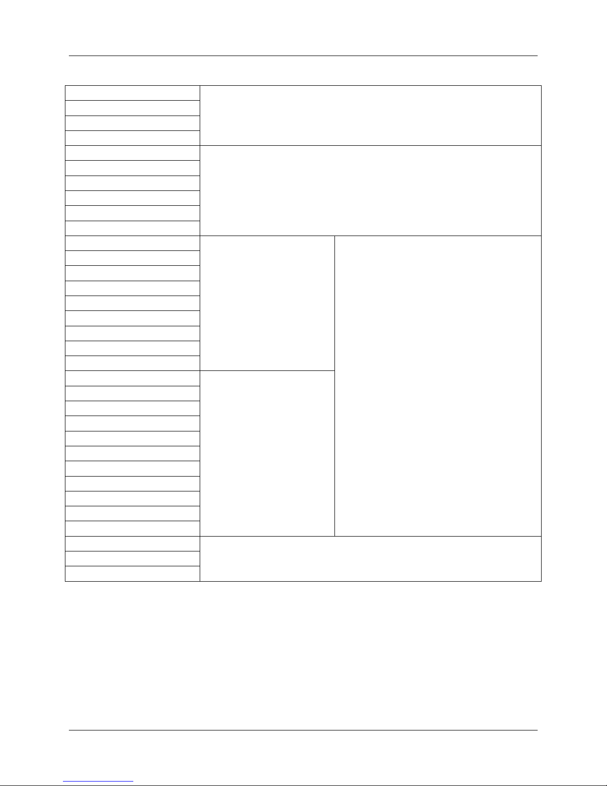
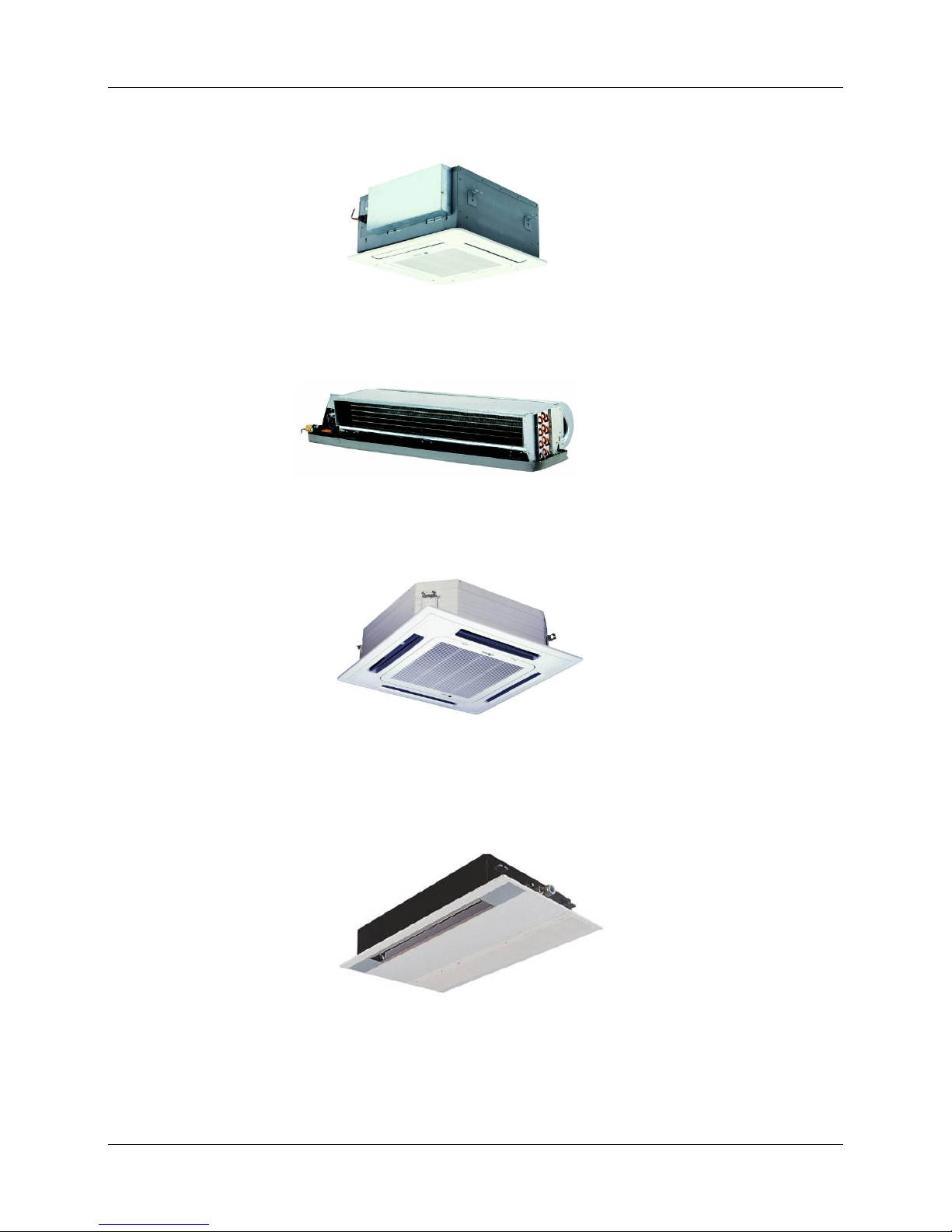
Compact four way cassette type
Duct type
Four way cassette type
One way cassette type
Page 7
MCAC-KTSM-2007-2 Nomenclature
General Information 5
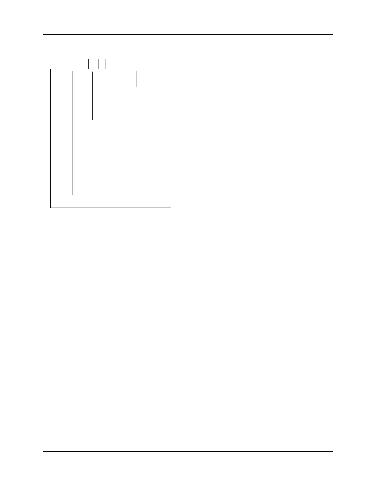
3. Nomenclature
KM
Nominal Air Volume(CFM)
Midea
Chilled Water Fan coil unit
-- 12Pa Static Pressure H 30Pa Static Pressure
F3 Concealed Flood-stand Type
F2 Exposed Flood-stand Type (below air intake)
Type Code
T2 2nd Generation Duct Type
A 4 Way Cassette B 4 Way Cassette (Compact)
C One Way Cassette T Duct
F1 Exposed Floor-stand Type (side air intake)
T1 127v 60 Hz Duct Type
Page 8

Features MCAC-KTSM-2007-2
6 Indoor Units
4. Features
Chilled water/Hot water (2 pipes)
Low height for easy installation
Low noise fan direct driven by single phase, 3 speed permanent split capacitor motor.
Copper tube/aluminum fin coils
Hydrophilic aluminum fin coils coated (optional)
Unit constructed by electrostatic galvanized sheet, providing maximum protection against corrosion
Heavy gauge zinc coated steel drainage pan with good insulation processing, avoiding sweating and
corrosion
Unit tested performance comply with GB4706.32-2004、JB9063-1999 and JB/T4283-1991.
Page 9

MCAC-KTSM-2007-2 Indoor Units
Indoor Units 7
Part 2
Indoor Units
Four Way Cassette Type …….................................................6
Compact Four Way Cassette Type.......................................25
Duct Type...............................................................................38
One Way Cassette Type ……..............................................106
Page 10

Four Way Cassette Type MCAC-KTSM-2007-2
8 Indoor Units
Four Way Cassette Type
1. Features…………………………………….......……………………….............. 9
2. Specification……………………………………………………………............ 10
3. Dimensions………………………………………………………………...........12
4. Service Space……………………………………………………………...........13
5. Wiring Diagrams…………………………………………………………..........14
6. Capacity Tables……………………………………………………………........15
7. Sound Levels……………………………………………………………...........22
8. Explored View……………………………………………………………..........23
Page 11
MCAC-KTSM-2007-2 Features
Four Way Cassette Type 9
1. Features
(1) Low operation noise
---Streamline plate ensures quietness
---Creates natural and comfortable environment
(2) Efficient cooling
---Equal, fast and wide—range cooling
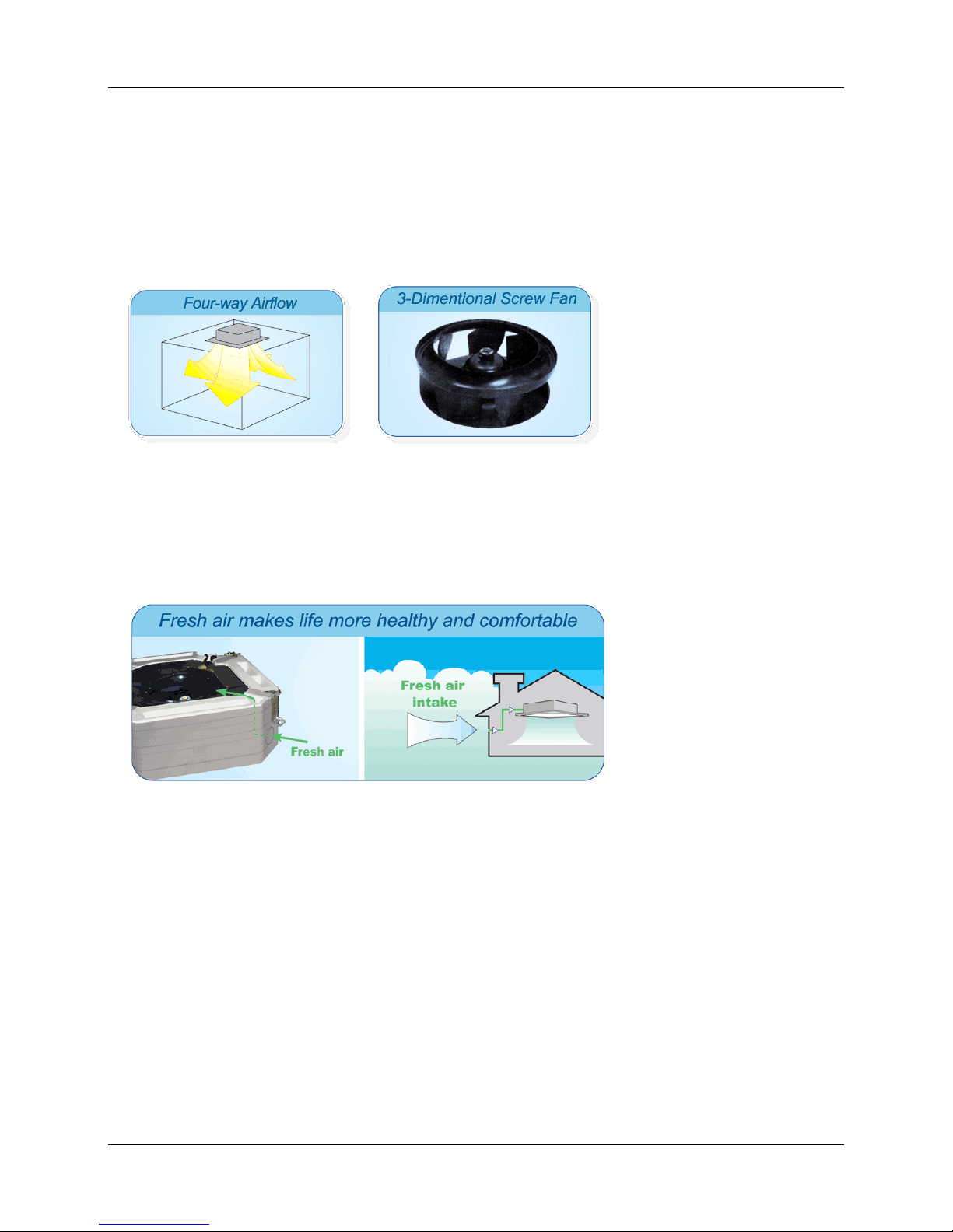
(3) The adoption of the most advanced 3- Dimensional Screw fan
---Reduces the air resistance passing through
---Smoothes the air flow
---Makes air speed distribution to the heat exchange uniform
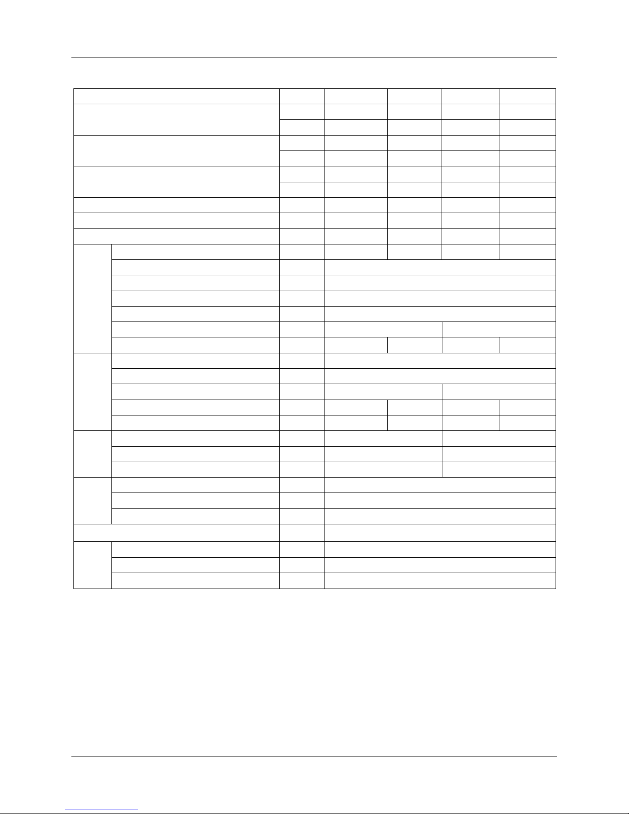
(4) Fresh air makes life healthier and more comfortable.
Page 12
Specification MCAC-KTSM-2007-2
10 Four Way Cassette Type
2. Specification
TYPE
MKA-950
MKA-850
MKA-750
MKA-600
Airflow
CFM
950
850
750
600
m3/h
1600
1400
1250
1000
Cooling Capacity
W
8110
7260
6385
5109
Btu/h
27635
24910
21835 17400
Heating Capacity
W
11311
10240
8850
7160
Btu/h
38690
34870
30570
24360
Noise
dB(A)
44
44
41
41
Water flow
LPH
1541
1382
1204
1005
Water resistance
kPa
30
27
25.2
23.8
Indoor
Coil
Number of rows
2 2 2 2
Tube pitch(a)x row pitch(b)
mm
25.4×22
Fin spacing
mm
1.3
Fin type
Hydrophilic aluminum
Tube outside dia.and type
mm
φ7,inner groove tube
Coil length x height x width
mm
2000×250×27
2000×170×27
Number of circuits
6 6 4 4
Fan
motor
Type
Low noise 3 speed fan motor
Number
1 Model YDK56-6
YDK55-6
Input W 144
144
128
120
Capacitor
uF
3.5
3.5
3.5
3.5
Indoor
unit
Dimension (W*H*D)
mm
840×310×840
840×240×840
Packing (W*H*D)
mm
1020×410×930
1020×330×930
Net/Gross weight
kg
40/50
36/46
Panel
Dimension (W*H*D)
mm
950×40×950
Packing (W*H*D)
mm
1030×145×1030
Net/Gross weight
kg
6/11
Control mode
wired controller(optional), remote controller (standard)
Pipe
Water-inlet pipe
RC3/4” internal thread
Water-return pipe RC3/4” internal thread
Condensation water-outlet pipe
EVA+LDPE 3/4” external thread
Remark: 1. All performance data above is based upon 0Pa ambient static pressure.
2. Cooling capacity test condition: air inlet Temp. : 27DB℃/19.5WB℃, water inlet Temp. 7℃,
water Temp. difference 5℃.
3. Heating capacity test condition:
Air inlet Temp. 21DB℃, water inlet Temp. 60 DB℃
The volume of air and water is same as cooling.
4. Noise level is tested in full-anechoic room.
Page 13
MCAC-KTSM-2007-2 Specifications
Four Way Cassette Type 11
Remark: 1. All performance data above is based upon 0Pa ambient static pressure.
2. Cooling capacity test condition: air inlet Temp. : 27DB℃/19.5WB℃, water inlet Temp. 7℃,
water Temp. difference 5℃.
3. Heating capacity test condition:
Air inlet Temp. 21DB℃, water inlet Temp. 60 DB℃
The volume of air and water is same as cooling.
4. Noise level is tested in full-anechoic room.
TYPE
MKA-1500
MKA-1200
Airflow
CFM
1500
1200
m3/h
2500
2000
Cooling Capacity
W
11556
9849
Btu/h
39240
33440
Heating Capacity
W
14920
13745
Btu/h
51000
46810
Noise
dB(A)
45
45
Water flow
LPH
2388
1928
Water resistance
kPa
46
44
Indoor
Coil
Number of rows
2 Tube pitch(a)x row pitch(b)
mm
25.4×22
Fin spacing
mm
1.3
Fin type
Hydrophilic aluminum
Tube outside dia.and type
mm
φ7,innergroove tube
Coil length x height x width
mm
2000×250×27
Number of circuits
6
Fan
motor
Type
Low noise 3 speed fan motor
Number
1 Model
YDK110-6
Input
W
190
180
Capacitor
uF
5
Indoor
unit
Dimension (W*H*D)
mm
840×310×840
Packing (W*H*D)
mm
1020×410×930
Net/Gross weight
kg
40/50
Panel
Dimension (W*H*D)
mm
950×40×950
Packing (W*H*D)
mm
1030×145×1030
Net/Gross weight
kg
6/11
Control mode
wired controller(optional) ,
remote controller (standard)
Pipe
Water-inlet pipe RC3/4” internal thread
Water-return pipe
RC3/4” internal thread
Condensation water-outlet pipe
EVA+LDPE 3/4” external thread
Page 14
Dimensions MCAC-KTSM-2007-2
12 Four Way Cassette Type
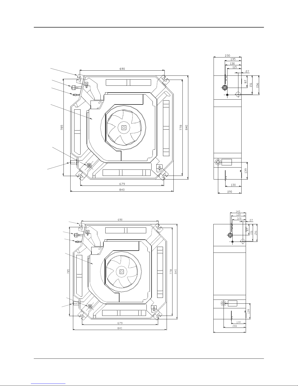
3. Dimensions
MKA-600、MKA-750
Gas side
E-parts box
Liquid side
4-install hanger
Drain hole
Pump
inspect hole
MKA-850、MKA-950、MKA-1200、MKA-1500
310
4-install
hanger
Gas side
liquid side
E-parts box
Pump
inspect hole
Drain hole
Page 15
MCAC-KTSM-2007-2 Service Space
Four Way Cassette Type 13
4. Service Spaces
MKA-600、MKA-750、MKA-850、MKA-950、MKA-1200、MKA-1500
Page 16
Wring Diagram MCAC-KTSM-2007-2
14 Four Way Cassette Type
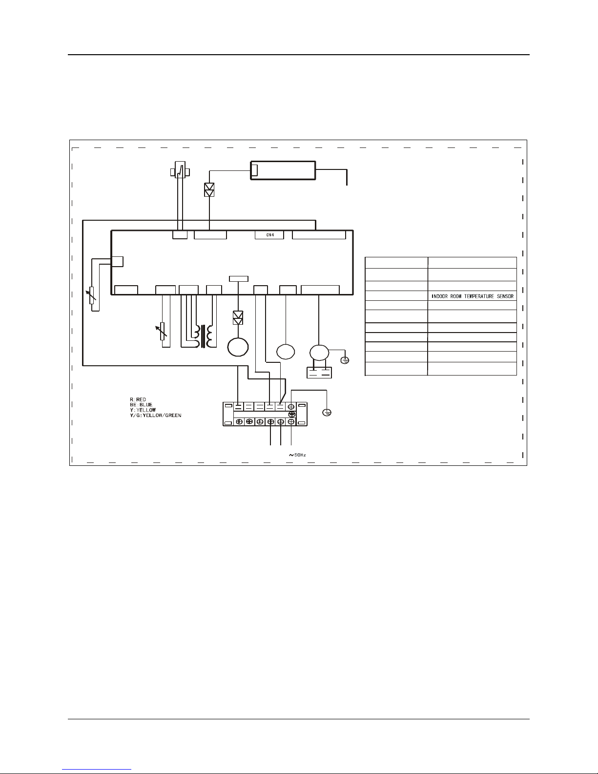
5. Wiring Diagram
MKA-600、MKA-750、MKA-850、MKA-950、MKA-1200、MKA-1500
XS1
XP1
R
POWER:220V-240V
MAINBOARD
XT1
L
T4
K3
INDOOR DRAWING
POWER:220V-240V~
50Hz
FAN1
BE
N
N1L1
PUMP
Y/G
CAP1
Y/G
XS1-XS2
Rt3
XT1
XP1-XP2
T4
K3
Rt2
FAN1
2CON10
DISPLAY
CAP1
CONNECTORS
6-WAY
TERMINAL
TRANSFORMER
PIPE TEMPERATURE SENSOR
PUMP WATER PUMP
CODE
WATER
LEVLE
INDOOR FAN
INDOOR FAN
PART
CAPACITOR
SWITCH
CN8
CN11 CN10
CN5
CN7
CN3
CN2
CN12
CN1 CN14 CN16
CN15
RT2
RT3
M
R Y
XS2
XP2
CONNECTORS
TO WIRE CONTROLER
(CHOICE)
REMARK:
Page 17

MCAC-KTSM-2007-2 Capacity Tables
Four Way Cassette Type 15
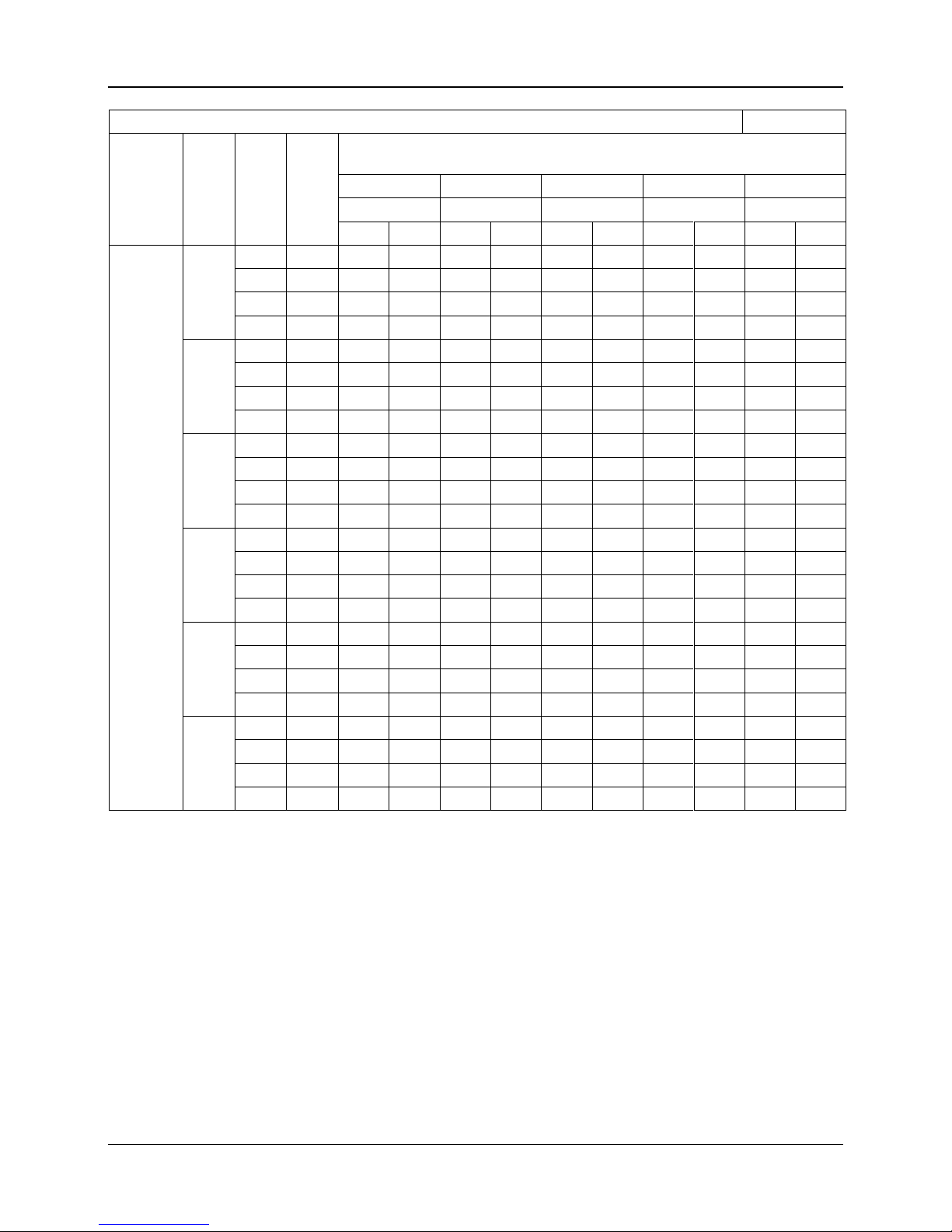
6. Capacity Tables
Cooling Capacity Table
Unit: W
Model
Water
inlet
temp.
(℃)
Water
FV
(LPM)
Water
PD
(kPa)
Air inlet condition
DB24℃
DB25℃
DB26℃
DB27℃
DB28℃
WB17℃
WB18℃
WB19℃
WB19.5℃
WB21℃
SH
TH
SH
TH
SH
TH
SH
TH
SH
TH
MKA-600
5
10
13.5
3439
4047
3537
4449
3636
4860
3823
5074
3823
5717
15
30.4
3716
4735
3850
5217
3975
5708
4172
5958
4207
6736
20
54
3913
5181
4056
5708
4199
6262
4404
6539
4467
7406
25
84.4
4029
5458
4181
6012
4333
6593
4547
6896
4627
7817 6 10
13.5
3296
3734
3404
4127
3502
4538
3689
4744
3689
5387
15
30.4
3555
4368
3689
4842
3815
5333
4011
5583
4047
6352
20
54
3734
4788
3877
6218
4020
5851
4225
6137
4297
6995
25
84.4
3841
5038
3993
5601
4154
6173
4359
6477
4449
7388 7 10
13.5
3162
3413
3270
3806
3368
4208
3555
4413
3564
5047
15
30.4
3395
4002
3529
4467
3654
4958
3850
5100
3895
5967
20
54
3555
4386
3707
4904
3850
5449
4056
5726
4118
6575
25
84.4
3654
4618
3815
5172
3966
5753
4181
6039
4261
6959 8 10
13.5
3028
3082
3136
3475
3234
3877
3421
4083
3430
4717
15
30.4
3243
3627
3368
4091
3502
4574
3698
4815
3743
5574
20
54
3386
3975
3529
4493
3672
5029
3877
5306
3949
6155
25
84.4
3466
4199
3627
4744
3788
5315
3993
5610
4083
6512 9 10
13.5
2894
2894
3002
3145
3109
3547
3296
3743
3305
4368
15
30.4
3082
3243
3216
3707
3341
4181
3538
4431
3591
5181
20
54
3207
3564
3359
4083
3502
4610
3707
4878
3779
5726
25
84.4
3287
3761
3448
4306
3600
4878
3815
5163
3904
6066
10
10
13.5
2760
2760
2877
2877
2975
3207
3162
3404
3180
4029
15
30.4
2930
2930
3064
3314
3189
3788
3386
4029
3439
4779
20
54
3037
3145
3189
3654
3332
4181
3538
4449
3618
5288
25
84.4
3109
3323
3270
3859
3421
4422
3636
4708
3725
5601
Remark:
1. DB: Dry Bulb Temp. WB: Wet Bulb Temp. FV: Flow Volume
TH: Total heat SH: Sensible heat PD: Pressure Drop
2. Table above is based on normal type fan coil high speed air-flow volume; cooling capacity on other speed
air flow volume should multiply with corresponding capacity modification coefficient (refer to capacity
modification coefficient diagram.)
Page 18
Capacity Tables MCAC -KTSM-2007-2
16 Four Way Cassette Type
Cooling Capacity Table
Unit: W
Model
Water
inlet
temp.
(℃)
Water
FV
(LPM)
Water
PD
(kPa)
Air inlet condition
DB24℃
DB25℃
DB26℃
DB27℃
DB28℃
WB17℃
WB18℃
WB19℃
WB19.5℃
WB21℃
SH
TH
SH
TH
SH
TH
SH
TH
SH
TH
MKA-750
5
15
11.9
4001
4838
4121
5316
4241
5811
4455
6058
4472
6839
20
21.2
4217
5372
4368
5907
4504
6465
4727
6752
4774
7636
25
33.1
4392
5779
4551
6369
4711
6975
4942
7285
5006
8250
30
47.7
4504
6034
4679
6656
4847
7294
5078
7772
5166
8640 6 15
11.9
3834
4455
3962
4934
4081
5421
4296
5676
4313
6448
20
21.2
4041
4950
4185
5492
4328
6042
4551
6448
4592
7206
25
33.1
4193
5333
4360
5922
4519
6520
4742
6831
4815
7787
30
47.7
4296
5580
4472
6193
4639
6831
4879
7158
4958
8162 7 15
11.9
3675
4073
3802
4551
3921
5038
4137
5284
4153
6050
20
21.2
3858
4536
4001
5309
4145
5779
4368
6385
4416
6767
25
33.1
4001
4886
4161
5548
4320
6146
4551
6433
4624
7326
30
47.7
4097
5110
4264
5723
4440
6353
4671
6679
4759
7684 8 15
11.9
3507
3690
3643
4161
3762
4639
3977
4886
4001
5644
20
21.2
3675
4105
3826
4639
3970
5181
4193
5539
4241
6321
25
33.1
3810
4432
3970
5006
4129
5603
4360
5907
4432
6847
30
47.7
3890
4639
4065
5245
4232
5875
4472
6193
4560
7189 9 15
11.9
3356
3356
3484
3762
3611
4241
3826
4487
3842
5237
20
21.2
3499
3675
3651
4200
3794
4742
4017
5022
4073
5875
25
33.1
3611
3970
3778
4543
3938
5134
4169
5436
4249
6369
30
47.7
3690
4161
3866
4759
4033
5380
4273
5699
4360
6688
10
15
11.9
3197
3197
3324
3364
3452
3842
3666
4081
3690
4830
20
21.2
3324
3324
3475
3762
3619
4296
3842
4568
3898
5421
25
33.1
3428
3499
3587
4065
3754
4655
3985
4950
4065
5882
30
47.7
3491
3666
3666
4264
3834
4886
4073
5197
4169
6177
Remark:
1. DB: Dry Bulb Temp. WB: Wet Bulb Temp. FV: Flow Volume
TH: Total heat SH: Sensible heat PD: Pressure Drop
2. Table above is based on normal type fan coil high speed air-flow volume; cooling capacity on other speed
air flow volume should multiply with corresponding capacity modification coefficient (refer to capacity
modification coefficient diagram.)
Page 19

Capacity Tables MCAC -KTSM-2007-2
Four Way Cassette Type 17
Cooling Capacity Table
unit:W
Model
Water
inlet
temp.
(℃)
Water
FV
(LPM)
Water
PD
(kPa)
Air inlet condition
DB24℃
DB25℃
DB26℃
DB27℃
DB28℃
WB17℃
WB18℃
WB19℃
WB19.5℃
WB21℃
SH
TH
SH
TH
SH
TH
SH
TH
SH
TH
MKA-850
5
15
11.9
4637
5607
4775
6161
4914
6734
5163
7020
5182
7925
20
21.2
4886
6225
5062
6844
5219
7491
5477
7823
5533
8849
25
33.1
5089
6697
5274
7380
5459
8082
5727
8442
5801
9560
30
47.7
5219
6992
5422
7713
5616
8452
5884
9006
5985
10013 6 15
11.9
4443
5163
4591
5717
4729
6281
4979
6576
4997
7472
20
21.2
4683
5736
4849
6364
5015
7001
5274
7472
5320
8350
25
33.1
4858
6179
5052
6863
5237
7556
5496
7916
5579
9024
30
47.7
4979
6466
5182
7177
5376
7916
5653
8295
5745
9458 7 15
11.9
4258
4720
4406
5274
4544
5838
4794
6124
4812
7011
20
21.2
4471
5256
4637
6152
4803
6697
5062
7260
5117
7842
25
33.1
4637
5662
4822
6429
5006
7121
5274
7454
5357
8488
30
47.7
4748
5921
4942
6632
5145
7362
5413
7740
5514
8904 8 15
11.9
4064
4277
4221
4822
4360
5376
4609
5662
4637
6540
20
21.2
4258
4757
4434
5376
4600
6004
4858
6419
4914
7325
25
33.1
4415
5136
4600
5801
4785
6493
5052
6844
5136
7934
30
47.7
4507
5376
4711
6078
4905
6807
5182
7177
5283
8331 9 15
11.9
3889
3889
4036
4360
4184
4914
4434
5200
4452
6068
20
21.2
4055
4258
4230
4868
4397
5496
4655
5819
4720
6807
25
33.1
4184
4600
4378
5265
4563
5948
4831
6299
4923
7380
30
47.7
4277
4822
4480
5514
4674
6235
4951
6604
5052
7750
10
15
11.9
3704
3704
3852
3898
3999
4452
4249
4729
4277
5597
20
21.2
3852
3852
4027
4360
4193
4979
4452
5293
4517
6281
25
33.1
3972
4055
4156
4711
4350
5394
4618
5736
4711
6817
30
47.7
4046
4249
4249
4942
4443
5662
4720
6022
4831
7158
Remark:
1. DB: Dry Bulb Temp. WB: Wet Bulb Temp. FV: Flow Volume
TH: Total heat SH: Sensible heat PD: Pressure Drop
2. Table above is based on normal type fan coil high speed air-flow volume; cooling capacity on other speed
air flow volume should multiply with corresponding capacity modification coefficient (refer to capacity
modification coefficient diagram.)
Page 20

Capacity Tables MCAC -KTSM-2007-2
18 Four Way Cassette Type
Cooling Capacity Table
Unit: W
Model
Water
inlet
temp.
(℃)
Water
FV
(LPM)
Water
PD
(kPa)
Air inlet condition
DB24℃
DB25℃
DB26℃
DB27℃
DB28℃
WB17℃
WB18℃
WB19℃
WB19.5℃
WB21℃
SH
TH
SH
TH
SH
TH
SH
TH
SH
TH
MKA-950
5
15
11.9
5180
6263
5334
6882
5490
7522
5768
7842
5789
8853
20
21.2
5459
6955
5654
7646
5830
8368
6118
8740
6180
9885
25
33.1
5686
7481
5891
8245
6098
9029
6397
9431
6480
10679
30
47.7
5830
7811
6057
8616
6274
9441
6573
10060
6686
11185 6 15
11.9
4963
5768
5128
6387
5283
7017
5561
7346
5582
8347
20
21.2
5232
6407
5417
7109
5603
7821
5891
8347
5944
9328
25
33.1
5428
6903
5644
7666
5850
8440
6139
8843
6232
10081
30
47.7
5561
7223
5789
8017
6005
8843
6315
9266
6418
10566 7 15
11.9
4757
5273
4922
5891
5076
6521
5355
6841
5376
7832
20
21.2
4994
5871
5180
6872
5365
7481
5654
8110
5717
8760
25
33.1
5180
6325
5386
7181
5592
7956
5891
8327
5985
9483
30
47.7
5304
6614
5520
7408
5747
8224
6047
8646
6160
9946 8 15
11.9
4540
4777
4716
5386
4870
6005
5148
6325
5180
7305
20
21.2
4757
5314
4953
6005
5138
6707
5428
7171
5490
8182
25
33.1
4933
5737
5138
6480
5345
7254
5644
7646
5737
8863
30
47.7
5035
6005
5262
6789
5479
7604
5789
8017
5902
9307 9 15
11.9
4344
4344
4509
4870
4675
5490
4953
5809
4974
6779
20
21.2
4530
4757
4726
5438
4911
6139
5201
6501
5273
7604
25
33.1
4675
5138
4890
5881
5097
6645
5396
7037
5500
8245
30
47.7
4777
5386
5004
6160
5221
6965
5531
7377
5644
8657
10
15
11.9
4137
4137
4303
4354
4468
4974
4747
5283
4777
6253
20
21.2
4303
4303
4499
4870
4685
5561
4974
5912
5046
7017
25
33.1
4437
4530
4643
5262
4860
6026
5159
6407
5262
7615
30
47.7
4519
4747
4747
5520
4963
6325
5273
6728
5396
7997
Remark:
1. DB: Dry Bulb Temp. WB: Wet Bulb Temp. FV: Flow Volume
TH: Total heat SH: Sensible heat PD: Pressure Drop
2. Table above is based on normal type fan coil high speed air-flow volume; cooling capacity on other speed
air flow volume should multiply with corresponding capacity modification coefficient (refer to capacity
modification coefficient diagram.)
Page 21

MCAC-KTSM-2007-2 Capacity Tables
Four Way Cassette Type 19
Cooling Capacity Table
Unit: W
Model
Water
inlet
temp.
(℃)
Water
FV
(LPM)
Water
PD
(kPa)
Air inlet condition
DB24℃
DB25℃
DB26℃
DB27℃
DB28℃
WB17℃
WB18℃
WB19℃
WB19.5℃
WB21℃
SH
TH
SH
TH
SH
TH
SH
TH
SH
TH
MKA-1200
5
25
18.2
6858
8651
7094
9517
7322
10418
7680
10873
7750
12282
32
29.8
7059
9141
7313
10060
7558
11022
7925
11503
8022
13017
35
35.6
7226
9526
7488
10497
7750
11494
8127
12011
8249
13603
40
46.5
7392
9832
7637
10838
7908
11879
8293
12413
8424
14066
6
25
18.2
6569
7978
6797
8844
7033
9736
7392
10191
7462
11591
32
29.8
6753
8433
7007
9360
7252
10305
7619
10786
7715
12290
35
35.6
6902
8800
7164
9762
7427
10751
7803
11267
7925
12842
40
46.5
7024
9089
7304
10086
7575
11118
7960
11652
8100
13734
7
25
18.2
6272
7304
6508
8162
6736
9045
7103
9054
7173
10882
32
29.8
6438
7724
6701
8634
6946
9579
7313
9849
7418
11547
35
35.6
6578
8057
6849
9010
7112
9999
7488
10506
7610
12081
40
46.5
6683
8328
6972
9316
7243
10348
7628
10873
7768
12509
8
25
18.2
5983
6613
6220
7471
6456
8345
6814
8791
6893
10174
32
29.8
6132
7007
6395
7908
6639
8844
7016
9316
7121
10795
35
35.6
6255
7304
6526
8258
6788
9238
7173
9745
7296
11293
40
46.5
6360
7558
6639
8538
6919
9561
7304
10086
7444
11704
9
25
18.2
5695
5922
5940
6762
6167
7637
6535
8074
6613
9447
32
29.8
5835
6272
6088
7173
6342
8100
6718
8573
6823
10034
35
35.6
5940
6543
6211
7488
6482
8468
6858
8966
6989
10506
40
46.5
6027
6771
6316
7750
6587
8765
6981
9281
7121
10891
10
25
18.2
5415
5415
5660
6053
5887
6919
6255
7357
6342
8713
32
29.8
5529
5529
5791
6421
6045
7339
6421
7812
6526
9264
35
35.6
5625
5773
5896
6709
6167
7672
6552
8170
6683
9701
40
46.5
5703
5975
5992
6946
6272
7952
6657
8468
6806
10060
Remark:
1. DB: Dry Bulb Temp. WB: Wet Bulb Temp. FV: Flow Volume
TH: Total heat SH: Sensible heat PD: Pressure Drop
2. Table above is based on normal type fan coil high speed air-flow volume; cooling capacity on other speed
air flow volume should multiply with corresponding capacity modification coefficient (refer to capacity
modification coefficient diagram.)
Page 22

Capacity Tables MCAC-KTSM-2007-2
20 Four Way Cassette Type
Cooling Capacity Table
Unit: W
Model
Water
inlet
temp.
(℃)
Water
FV
(LPM)
Water
PD
(kPa)
Air inlet condition
DB24℃
DB25℃
DB26℃
DB27℃
DB28℃
WB17℃
WB18℃
WB19℃
WB19.5℃
WB21℃
SH
TH
SH
TH
SH
TH
SH
TH
SH
TH
MKA-1500
5
25
18.2
8047
10151
8324
11167
8591
12224
9012
12758
9094
14410
32
29.8
8283
10726
8581
11803
8868
12932
9299
13497
9412
15273
35
35.6
8478
11177
8786
12317
9094
13487
9535
14092
9679
15960
40
46.5
8673
11536
8960
12717
9278
13938
9730
14564
9884
16504 6 25
18.2
7708
9361
7975
10377
8252
11424
8673
11957
8755
13600
32
29.8
7924
9894
8221
10982
8509
12091
8940
12655
9053
14421
35
35.6
8098
10325
8406
11454
8714
12614
9155
13220
9299
15067
40
46.5
8242
10664
8570
11834
8888
13045
9340
13671
9504
16114 7 25
18.2
7359
8570
7636
9576
7903
10613
8334
10623
8416
12768
32
29.8
7554
9063
7862
10130
8149
11239
8581
11556
8704
13548
35
35.6
7718
9453
8037
10572
8344
11732
8786
12327
8929
14174
40
46.5
7842
9771
8180
10931
8498
12142
8950
12758
9114
14677 8 25
18.2
7020
7759
7298
8765
7575
9792
7995
10315
8088
11937
32
29.8
7195
8221
7503
9278
7790
10377
8232
10931
8355
12666
35
35.6
7339
8570
7657
9689
7965
10839
8416
11434
8560
13251
40
46.5
7462
8868
7790
10017
8119
11218
8570
11834
8734
13733 9 25
18.2
6682
6949
6969
7934
7236
8960
7667
9473
7759
11085
32
29.8
6846
7359
7144
8416
7441
9504
7883
10059
8006
11773
35
35.6
6969
7677
7287
8786
7605
9935
8047
10520
8201
12327
40
46.5
7072
7944
7410
9094
7729
10284
8191
10890
8355
12778
10
25
18.2
6353
6353
6641
7103
6908
8119
7339
8632
7441
10223
32
29.8
6487
6487
6795
7534
7092
8611
7534
9166
7657
10869
35
35.6
6600
6774
6918
7872
7236
9001
7688
9586
7842
11383
40
46.5
6692
7010
7031
8149
7359
9330
7811
9935
7985
11803
Remark:
1. DB: Dry Bulb Temp. WB: Wet Bulb Temp. FV: Flow Volume
TH: Total heat SH: Sensible heat PD: Pressure Drop
2. Table above is based on normal type fan coil high speed air-flow volume; cooling capacity on other speed
air flow volume should multiply with corresponding capacity modification coefficient (refer to capacity
modification coefficient diagram.)
Page 23

MCAC-KTSM-2007-2 Capacity Tables
Four Way Cassette Type 21
Heating Capacity Table:
Model
Water Flow
volume(LPM)
Hydraulic
Pressure
Drop (kPa)
Air inlet condition DB18℃
Water inlet temp.
40
45
50
55
60
70
80
MKA-600
10
13.5
3791
4650
5509
6375
7234
8959
10684
15
30.4
4087
5013
5946
6871
7804
9663
11521
20
54
4257
5227
6190
7160
8130
10063
12002
25
84.4
4369
5361
6353
7345
8337
10329
12313
MKA-750
15
11.9
4589
5641
6839
7659
8850
10926
13042
20
21.2
4777
5870
6960
8044
9114
11280
13454
25
33.1
4978
6114
7247
8384
9486
11748
14008
30
47.7
5109
6270
7438
8601
9738
12051
14372
MKA-850
15
11.9
5097
6261
7418
8582
9738
12058
14379
20
21.2
5363
6581
7806
9023
10240
12682
15117
25
33.1
5538
6794
8057
9312
10575
13093
15611
30
47.7
5660
6946
8239
9525
10811
13382
15961
MKA-950
15
11.9
5869
7199
8537
9868
11180
13830
16498
20
21.2
6174
7574
8971
10383
11754
14553
17351
25
33.1
6366
7820
9270
10716
12139
15025
17920
30
47.7
6518
7997
9473
10954
12403
15358
18315
MKA-1200
25
18.2
7315
8976
10637
12305
12694
17295
20617
32
29.8
7527
9238
10955
12666
14376
17804
21225
35
35.6
7690
9443
11189
12941
14687
18186
21684
40
46.5
7817
9598
11372
13153
14935
18490
22045
MKA-1500
25
18.2
7761
9529
11293
13063
14794
18305
21838
32
29.8
8063
9893
11729
13561
15353
19008
22666
35
35.6
8271
10155
12035
13912
15758
19502
23268
40
46.5
8437
10347
12263
14186
16066
19882
23710
Remark:
1. DB: Dry Bulb Temp. WB: Wet Bulb Temp.
TH: Total heat SH: Sensible heat
2. Table above is based on normal type fan coil high speed air-flow volume; heating capacity on other speed
air flow volume should multiply with corresponding capacity modification coefficient (refer to capacity
modification coefficient diagram.)
Page 24

Sound Levels MCAC-KTSM-2007-2
22 Four Way Cassette Type
7. Sound Levels
TYPE
MKA-600
MKA-750
MKA-850
MKA-950
MKA-1200
MKA-1500
Noise
dB(A)
41
41
44
44
45
45
FOUR-WAY CASSETTE TYPE
Microphone
1.0m
Page 25

MCAC-KTSM-2007-2 Explored View
Four Way Cassette Type 23
8. Exploded View
MKA-600、MKA-750、MKA-850、MKA-950、MKA-1200、MKA-1500
No.
Part Name
Quantity
No.
Part Name
Quantity
1
Water Receiver, Assembly
1
26
Rubber washer, pump
1
2
Pipe Temperature Sensor Assembly
1
27
holder, pump
1
3
E-Parts Box Cover1
1
28
Water trying board
1
4
Capacity
1
29
Panel Assembly
4
5
E-Parts Box Assembly
1
30
Cover, installing
1
6
E-Parts Box Cover2
1
31
Swing motor
4
7
Transformer
1
32
Fan guide
1
8
PCB Assembly
1
33
Filter
2
9
Evaporator assembly
1
34
Switch, air inlet grille
1
1
2
3 4 5
6
7
8
10
9
11
12
13
14
15
16
17
18
20
21
22
23
24
25
26
27
28
29
30
31
32
33
34
35
36
37
38
394041
42
43
44
45
46
47
48
49
50
19
56
Page 26

Explored View MCAC-KTSM-2007-2
24 Four Way Cassette Type
10
Fixing board, Evaporator
1
35
Switch cover, air inlet grille
1
11
Clamp, fan
1
36
Air inlet grille
4
12
Fan assembly
1
37
Hanger for panel, assembly
1
13
Fan Motor
1
38
Control box
1
14
Gasket, motor
4
39
LED holder
1
Gasket, motor
4
40
Control board
1
15
Evaporator Base assembly
1
41
Cover, control box
1
16
Base Pan assembly
1
42
Panel
1
Wire clamp board
1
43
Back board, Air out 1
1
17
Sealing board, pipe out
1
44
Back board, Air out 2
1
18
Remoter
1
45
Back board, Air out 3
1
19
Eva out pipe, assembly
1
46
Back board, Air out 4
4
20
Drain Pump assembly
1
47
Foam, air out 1
4
21
Water switch
1
Foam, air out 2
1
22
Clamp, water pipe
1
48
Fixing hanger, Evaporator
2
23
Water pipe
1
49
Fixing hanger, Evaporator
1
24
Extend water pipe
1
50
Eva in pipe, assembly
25
Separate board, pump
1
Page 27

MCAC-KTSM-2007-2 Compact Four Way Cassette Type
Compact Four Way Cassette Type 25
Compact Four Way Cassette Type
1. Features..........……………………………………………………………............26
2. Specification……………………………………………………………............27
3. Dimensions………………………………………………………………...........28
4. Service Space……………………………………………………………............29
5. Wiring Diagrams…………………………………………………………..........30
6. Capacity Tables……………………………………………………………........31
7. Sound Levels……………………………………………………………..........35
8. Explored View……………………………………………………………..........36
Page 28

Features MCAC-KTSM-2007-2
26 Compact Four Way Cassette Type
1. Features
(1) Low operation noise
---Streamline plate ensures quietness
---Creates natural and comfortable environment
(2) Efficient cooling
---Equal, fast and wide—range cooling
(3) The adoption of the most advanced 3- Dimensional Screw fan
---Reduces the air resistance passing through
---Smoothes the air flow
---Makes air speed distribution to the heat exchange uniform
(4) Fresh air makes life healthier and more comfortable.
(4) Improvement for easy installation and maintenance (only available for small four-way cassette)
---Little space is required for installation into a shallow ceiling
---Because of the compactness and weight reduction of the main unit and panel, all models can be
installed without a hoist
The sketch map of installation (compact type)
Page 29

MCAC-KTSM-2007-2 Specification
Compact Four Way Cassette Type 27
2. Specification
TYPE
MKB-300
MKB-400
MKB-450
MKB-500
Airflow
CFM
300
400
450
500
m3/h
500
630
710
800
Cooling Capacity
W
2635
3190
3750
3935
Btu/h
8870
10920
12625
13310
Heating Capacity
W
3630
4425
5240
5510
Btu/h
12420
15285
17675
18630
Noise
dB(A)
38
39
40
41
Water flow
LPH
530
653
740
850
Water resistance
kPa
10.1
14.5
18.3
27.1
Indoor Coil
Number of rows
2 2 2 2
Tube pitch(a)x row pitch(b)
mm
21×13.37
Fin spacing
mm
1.3
Fin type Hydrophilic aluminium
Tube outside dia.and type
mm
φ7.94,innergroove tube
Coil length×height×width
mm
1185×210×26.74
Number of circuits
10
10
10
10
Fan
motor
Type Low noise 3 speed fan motor
Number
1 Model
YDK45-4F
Input W 30
45
55
70
Capacitor
uF 1 1.5 2 3
Indoor
unit
Dimension (W*H*D)
mm
580×254×580
Packing (W*H*D)
mm
750×340×750
Net/Gross weight
kg
21/30
Panel
Dimension (W*H*D)
mm
650×30×650
Packing (W*H*D)
mm
715×115×715
Net/Gross weight
kg
3/5
Control mode
wired controller(optional) , remote controller
(standard)
Pipe
Water-inlet pipe
RC3/4” internal thread
Water-return pipe
RC3/4” internal thread
Condensation water-outlet pipe
EVA+LDPE 3/4” external thread
Remark: 1. All performance data above is based upon 0Pa ambient static pressure.
2. Cooling capacity test condition: air inlet Temp. : 27DB℃/19.5WB℃, water inlet Temp. 7℃,
water Temp. difference 5℃.
3. Heating capacity test condition:
air inlet Temp. 21DB℃, water inlet Temp. 60 DB℃
the volume of air and water is same as cooling.
4. Noise level is tested in full-anechoic room.
Page 30

Dimensions MCAC-KTSM-2007-2
28 Compact Four Way Cassette Type
3. Dimensions
MKB-300、MKB-400、MKB-450、MKB-500
580(Body)
67
600(Ceiling hole)
650(Panel)
401(Hook-location)
611(Hook-location)
580(Body)
422 28.5
600(Ceiling hole)
650(Panel)
Drain side and
Tubing side
A
600
Hook
265
Panel
Chart 4
Body
Nut
Ceiling
Page 31

MCAC-KTSM-2007-2 Service Space
Compact Four Way Cassette Type 29
4. Service Space
Page 32

Wring Diagram MCAC-KTSM-2007-2
30 Compact Four Way Cassette
5. Wiring Diagram
CN7
CN 11 C N1 0
CN2
CN 19
CN1
CN5
CN 12
CN4 CN8 CN9
CN 17
T O CON T R OL E R
5
CN3
2
Y
BL
Page 33

MCAC-KTSM-2007-2 Capacity Tables
Compact Four Way Cassette Type 31
6. Capacity Tables
Cooling Capacity Table
unit:W
Model
Water
inlet
temp.
(℃)
Water
FV
(LPM)
Water
PD
(kPa)
Air inlet condition
DB24℃
DB25℃
DB26℃
DB27℃
DB28℃
WB17℃
WB18℃
WB19℃
WB19.5℃
WB21℃
SH
TH
SH
TH
SH
TH
SH
TH
SH
TH
MKB-300
5
6
4.6
1531
1809
1578
1989
1620
2170
1709
2273
1703
2553 8 8.1
1627
2038
1683
2239
1731
2448
1822
2559
1836
2886
10
12.7
1692
2193
1755
2414
1815
2643
1899
2761
1927
3122
12
18.2
1753
2322
1815
2559
1878
2810
1968
2935
2003
3324 6 6
4.6
1474
1669
1516
1843
1565
2024
1648
2121
1648
2406 8 8.1
1558
1878
1613
2079
1662
2288
1753
2392
1767
2726
10
12.7
1523
1620
1676
2246
1739
2476
1829
2587
1850
2948
12
18.2
1669
2149
1739
2385
1802
2629
1892
2754
1927
3144 7 6
4.6
1412
1523
1460
1696
1502
1878
1584
1974
1585
2253 8 8.1
1488
1717
1544
1920
1601
2130
1717
2267
1696
2559
10
12.7
1544
1850
1606
2072
1662
2295
1753
2635
1781
2775
12
18.2
1592
1968
1655
2336
1724
2608
1815
2816
1843
2955 8 6
4.6
1349
1377
1398
1551
1446
1731
1530
1822
1530
2107 8 8.1
1419
1558
1474
1753
1530
1961
1609
2061
1634
2392
10
12.7
1467
1676
1530
1899
1592
2121
1683
2239
1703
2594
12
18.2
1509
1788
1578
2017
1641
2260
1739
2378
1767
2761 9 6
4.6
1294
1294
1342
1405
1384
1585
1467
1676
1474
1954 8 8.1
1356
1391
1412
1592
1467
1795
1551
1899
1565
2218
10
12.7
1398
1502
1537
1717
1516
1940
1606
2059
1634
2406
12
18.2
1433
1599
1502
1829
1565
2072
1662
2190
1690
2573
10
6
4.6
1182
1231
1280
1280
1328
1433
1412
1523
1419
1802 8 8.1
1287
1287
1342
1419
1398
1627
1488
1724
1502
2045
10
12.7
1321
1321
1384
1537
1446
1760
1537
1871
1565
2225
12
18.2
1356
1412
1426
1641
1488
1878
1585
1996
1620
2371
Remark:
1. DB: Dry Bulb Temp. WB: Wet Bulb Temp. FV: Flow Volume
TH: Total heat SH: Sensible heat PD: Pressure Drop
2. Table above is based on normal type fan coil high speed air-flow volume; cooling capacity on other speed
air flow volume should multiply with corresponding capacity modification coefficient (refer to capacity
modification coefficient diagram.)
Page 34

Capacity Tables MCAC-KTSM-2007-2
32 Compact Four Way Cassette Type
Cooling Capacity Table
Unit: W
Model
Water
inlet
temp.
(℃)
Water
FV
(LPM)
Water
PD
(kPa)
Air inlet condition
DB24℃
DB25℃
DB26℃
DB27℃
DB28℃
WB17℃
WB18℃
WB19℃
WB19.5℃
WB21℃
SH
TH
SH
TH
SH
TH
SH
TH
SH
TH
MKB-400
5
6
4.6
1852
2188
1911
2407
1961
2626
2062
2744
2062
3089 8 8.1
1970
2466
2037
2710
2096
2963
2205
3097
2222
3493
10
12.7
2045
2651
2121
2921
2197
3198
2298
3342
2331
3779
12
18.2
2121
2811
2197
3097
2273
3400
2382
3552
2424
4023 6 6
4.6
1784
2020
1835
2230
1894
2449
1995
2567
1995
2912 8 8.1
1885
2273
1953
2517
2012
2769
2121
2895
2138
3299
10
12.7
1843
1961
2028
2719
2104
2996
2214
3131
2239
3569
12
18.2
2020
2601
2104
2887
2180
3182
2289
3333
2331
3804 7 6
4.6
1709
1843
1768
2054
1818
2273
1919
2390
1919
2727 8 8.1
1801
2079
1869
2323
1936
2576
2037
2702
2054
3097
10
12.7
1869
2239
1944
2508
2012
2778
2121
3190
2155
3358
12
18.2
1927
2382
2003
2828
2087
3156
2197
3409
2230
3577 8 6
4.6
1633
1667
1692
1877
1751
2096
1852
2205
1852
2550 8 8.1
1717
1885
1784
2121
1852
2374
1953
2500
1978
2895
10
12.7
1776
2028
1852
2298
1927
2567
2037
2710
2062
3139
12
18.2
1826
2163
1911
2441
1986
2735
2104
2879
2138
3342 9 6
4.6
1566
1566
1624
1700
1675
1919
1776
2028
1784
2365 8 8.1
1641
1683
1709
1927
1776
2172
1877
2298
1894
2685
10
12.7
1692
1818
1860
2079
1835
2348
1944
2491
1978
2912
12
18.2
1734
1936
1818
2214
1894
2508
2012
2651
2045
3114
10
6
4.6
1431
1490
1549
1549
1608
1734
1709
1843
1717
2180 8 8.1
1557
1557
1624
1717
1692
1970
1801
2087
1818
2475
10
12.7
1599
1599
1675
1860
1751
2129
1860
2264
1894
2693
12
18.2
1641
1709
1725
1986
1801
2273
1919
2416
1961
2870
Remark:
1. DB: Dry Bulb Temp. WB: Wet Bulb Temp. FV: Flow Volume
TH: Total heat SH: Sensible heat PD: Pressure Drop
2. Table above is based on normal type fan coil high speed air-flow volume; cooling capacity on other speed
air flow volume should multiply with corresponding capacity modification coefficient (refer to capacity
modification coefficient diagram.)
Page 35

MCAC-KTSM-2007-2 Capacity Tables
Compact Four Way Cassette Type 33
Cooling Capacity Table
Unit: W
Model
Water
inlet
temp.
(℃)
Water
FV
(LPM)
Water
PD
(kPa)
Air inlet condition
DB24℃
DB25℃
DB26℃
DB27℃
DB28℃
WB17℃
WB18℃
WB19℃
WB19.5℃
WB21℃
SH
TH
SH
TH
SH
TH
SH
TH
SH
TH
MKB-450
5
6
4.6
2305
2693
2366
2955
2435
3227
2559
3366
2552
3793 8 8.1
2505
3180
2591
3498
2676
3832
2808
4002
2831
4522
10
12.7
2629
3475
2722
3832
2823
4196
2955
4382
3002
4964
12
18.2
2722
3692
2831
4072
2932
4467
3079
4669
3134
5290 6 6
4.6
2210
2482
2280
2746
2342
3009
2466
3149
2466
3576 8 8.1
2397
2932
2482
3250
2567
3584
2699
3747
2722
4266
10
12.7
2513
3211
2606
3560
2707
3924
2839
4110
2885
4684
12
18.2
2598
3413
2707
3793
2808
4180
2947
4382
3009
5003 7 6
4.6
2117
2265
2187
2528
2257
2792
2381
2932
2381
3351 8 8.1
2288
2684
2373
3002
2459
2994
2590
3280
2622
3863
10
12.7
2389
2940
2490
3134
2583
3266
2722
3506
2769
4095
12
18.2
2473
3125
2575
3273
2683
3474
2823
3750
2885
4312 8 6
4.6
2032
2047
2102
2311
2172
2575
2303
2707
2296
3126 8 8.1
2179
2435
2272
2746
2358
3072
2490
3234
2513
3747
10
12.7
2272
2668
2373
3009
2474
3374
2606
3553
2653
4126
12
18.2
2342
2839
2451
3211
2559
3599
2699
3553
2761
4095 9 6
4.6
1939
1939
2016
2086
2078
2350
2203
2490
2210
2901 8 8.1
2078
2179
2164
2490
2249
2808
2381
2971
2412
3475
10
12.7
2156
2389
2257
2730
2358
3087
2497
3273
2544
3832
12
18.2
2218
2544
2327
2916
2435
3219
2583
3351
2645
3871
10
6
4.6
1853
1853
1923
1923
1993
2125
2117
2257
2125
2668 8 8.1
1970
1970
2063
2226
2148
2544
2280
2707
2311
3211
10
12.7
2047
2102
2141
2451
2241
2800
2381
2978
2428
3545
12
18.2
2102
2249
2210
2614
2319
2994
2459
3188
2521
3638
Remark:
1. DB: Dry Bulb Temp. WB: Wet Bulb Temp. FV: Flow Volume
TH: Total heat SH: Sensible heat PD: Pressure Drop
2. Table above is based on normal type fan coil high speed air-flow volume; cooling capacity on other speed
air flow volume should multiply with corresponding capacity modification coefficient (refer to capacity
modification coefficient diagram.)
Page 36

Capacity Tables MCAC-KTSM-2007-2
34 Compact Four Way Cassette Type
Cooling Capacity Table
Unit: W
Model
Water
inlet
temp.
(℃)
Water
FV
(LPM)
Water
PD
(kPa)
Air inlet condition
DB24℃
DB25℃
DB26℃
DB27℃
DB28℃
WB17℃
WB18℃
WB19℃
WB19.5℃
WB21℃
SH
TH
SH
TH
SH
TH
SH
TH
SH
TH
MKB-500
5
10
13.5
2759
3646
2857
4020
2962
4403
3101
4598
3150
5209
15
30.4
2857
3874
2971
4273
3076
4688
3231
4899
3288
5551
20
54
2319
2604
2393
2881
2458
3158
2588
3304
2588
3752
25
84.4
2515
3076
2604
3410
2694
3760
2832
3931
2857
4476 6 10
13.5
2637
3369
2735
3736
2840
4118
2979
4313
3028
4916
15
30.4
2726
3581
2840
3980
2946
4387
3093
4598
3158
5249
20
54
2222
2376
2295
2653
2368
2930
2499
3076
2499
3516
25
84.4
2401
2816
2490
3150
2580
3141
2718
3443
2751
4053 7 10
13.5
2507
3085
2612
3288
2710
3426
2857
3679
2905
4297
15
30.4
2596
3280
2702
3434
2816
3646
2962
3935
3028
4525
20
54
2132
2149
2206
2425
2279
2702
2417
2840
2409
3280
25
84.4
2287
2556
2385
2881
2474
3223
2612
3394
2637
3931 8 10
13.5
2385
2800
2490
3158
2596
3540
2735
3727
2783
4330
15
30.4
2458
2979
2572
3369
2686
3776
2832
3727
2897
4297
20
54
2035
2035
2116
2189
2181
2466
2311
2612
2319
3044
25
84.4
2181
2287
2271
2612
2360
2946
2499
3117
2531
3646 9 10
13.5
2263
2507
2368
2865
2474
3239
2621
3434
2669
4020
15
30.4
2328
2669
2442
3060
2556
3378
2710
3516
2775
4061
20
54
1945
1945
2018
2018
2092
2230
2222
2368
2230
2800
25
84.4
2067
2067
2165
2336
2254
2669
2393
2840
2425
3369
10
10
13.5
2149
2206
2246
2572
2352
2938
2499
3125
2547
3719
15
30.4
2206
2360
2319
2743
2433
3141
2580
3345
2645
3817
20
54
2343
2426
2460
2819
2571
3226
2730
3433
2792
4081
25
84.4
2398
2564
2523
2978
2640
3412
2805
3632
2875
4322
Remark:
1. DB: Dry Bulb Temp. WB: Wet Bulb Temp. FV: Flow Volume
TH: Total heat SH: Sensible heat PD: Pressure Drop
2. Table above is based on normal type fan coil high speed air-flow volume; cooling capacity on other speed
air flow volume should multiply with corresponding capacity modification coefficient (refer to capacity
modification coefficient diagram.)
Page 37

MCAC-KTSM-2007-2 Sound Levels
Compact Four Way Cassette Type 35
7. Sound Levels
TYPE
MKB-300
MKB-400
MKB-450
MKB-600
Noise
dB(A)
38
39
40
41
FOUR-WAY CASSETTE TYPE
Microphone
1.0m
Page 38

Explored View MCAC-KTSM-2007-2
36 Compact Four Way Cassette Type
8. Explored View
MKB-300、MKB-400、MKB-450、MKB-500
No.
Part Name
Quantity
No.
Part Name
Quantity
1
Collect Water Pan ,Assembly
1
26.1
Air inlet grille
1
1.1
Foam, Collect Water Pan
1
26.2
Switch cover, air inlet grille
1
2
Wire fixing board
1
26.3
Switch, air inlet grille
2
3
Stopper, Water Drain
1
26.4
Filter 1 5
Evaporator Fixture Board Assembly
1
26.5
Control box
1
6
Drain Pump
1
26.6
LED holder
1
7
Liquid Position Sensor Assembly
1
26.7
Control board
1
8
Desperation board, right
1
26.8
Cover, control box
1
9
Drain pipe
1
26.9
Fan guide
4
1
2
1.1
5
3
6 7 8 910
11
13
14
15 17
18
19
20
21
22
23
25
24
26
26.1
26.2
26.3
26.4
26.5
26.6
26.7
26.8
26.9
26.10
26.11
26.12
26.13
26.14
26.15
29.1
27
29
30
29.2
29.3
29.4
29.7
29.8
29.6
Page 39

MCAC-KTSM-2007-2 Explored View
Compact Four Way Cassette Type 37
10
Extend water pipe
1
26.10
Swing motor
1
11
Drain Pump Holder
1
26.11
Panel
1
13
Evaporator Assembly
1
26.12
Install cover, swing motor
1
14
Fixing clamp, evaporator
1
26.13
Install cover I
1
15
Desperation board, left
1
26.14
Install cover II
1
16
Inlet pipe, evaporator
1
26.15
Install cover I
1
17
Outlet pipe, evaporator
1
27
Remoter
1
18
Wire crossing board
1
29
E-control Assembly
1
19
Fan 1 29.1
Control Box
1
20
Fan Motor
1
29.2
Rubber, wire crossing
1
21
Fan Motor Underlay
1
29.3
PCB Assembly
1
22
Base Pan Assembly
1
29.4
Transformer
1
23
Fixing board, water pan
4
29.6
Capacitor
1
24
Sealing board, pipe out I
1
29.7
Base, wire fixing
1
24.1
Sealing board, pipe outⅡ
1
29.8
Cover, wire fixing
1
25
Rubber, wire c
2
30
Control Box Cover
1
26
Panel Assembly
1
Page 40

The Installation of MKA MCAC-KTSM-2007-2
142 The Installation of MKA
The Installation of MKA
1. Before Installation …………………………………………………................143
2. Install the Main Body...…………………………………………………...........144
3. Install the Panel...…………………………………………………..............146
4. Install the Drain Pipe...…………………………………………………...........148
5. Wiring...…………………………………………………...................................150
Page 41

MCAC-KTSM-2007-2 Before Installation
The Installation of MKA 143
1. Before Installation
Please check whether the accessories are of full scope. If there are some fittings free from use, please
restore them carefully.
Page 42

Install The Main Body MCAC-KTSM-2007-2
144 The Installation of MKA
2. Install the Main Body
A. The existing ceiling (to be horizontal)
a. Please cut a quadrangular hole of 880 880mm in the ceiling according to the shape of the installation
paper board. (Refer to Chart3, 4)
The center of the hole should be at the same position of that of the air conditioner body.
Determine the lengths and outlets of the connecting pipe, drain pipe and cables.
To balance the ceiling and to avoid vibration, please enforce the ceiling when necessary.
b. Please select the position of installation hooks according to the hook holes on the installation board.
Drill four holes of Ø12mm, 50~55mm deep at the selected positions on the ceiling. Then embed the
expansible hooks (fittings).
Face the concave side of the installation hooks toward the expansible hooks. Determine the length of the
installation hooks from the height of ceiling, and then cut off the unnecessary part.
If the ceiling is extremely high, please determine the length of the installation hook according to facts.
Cut the installation hook open in the middle position, and then use appropriate length of reinforcing rod (Ø12)
to weld together.
The length could be calculated from Chart5:
Length=H-181+L (in general, L=100mm and is half of the whole length of the installation hook).
c. Please adjust the hexangular nuts on the four installation hooks evenly, to ensure the balance of the body.
1. The transparent hose filled with water to check the lever of the main body from the four sides or diagonal
line direction, the lever indicator also can check the lever from four sides of the main body Refer to chart 6)
2. The drainpipe is awry, leakage will be caused by the malfunction of the water-level switch.
Adjust the position to ensure the gaps between the body and the four sides of ceiling are even.
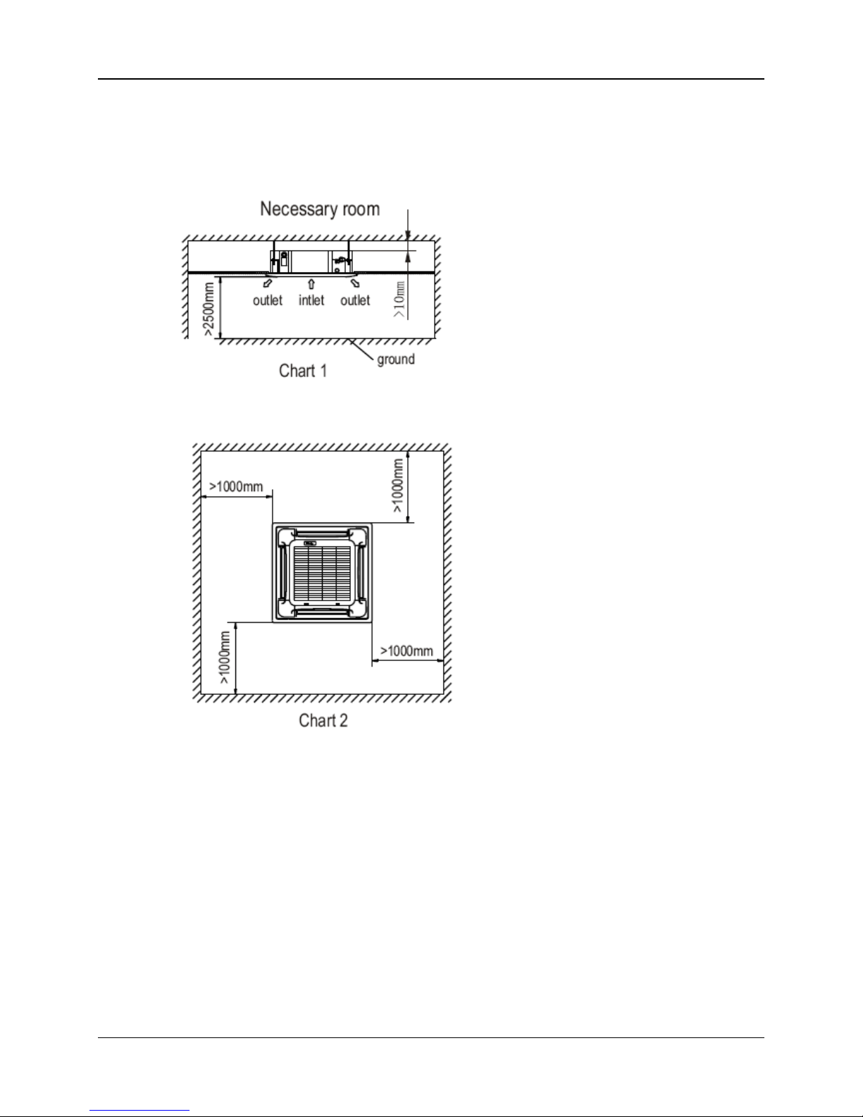
3. The body's lower part should sink into the ceiling for 10~12mm (Refer to chart5).
Locate the air conditioner firmly by wrenching the nuts after having adjusted the body's position well.
Page 43

MCAC-KTSM-2007-2 Install The Main Body
The Installation of MKA 145
B. New built houses and ceilings
a. In the case of new built house, the hook can be embedded in advance (refer to the A.b mentioned above).
But it should be strong enough to bear the indoor unit and will not become loose because of concrete
shrinking.
b. After installing the body, please fasten the installation paper board onto the air conditioner with bolts (M6
16) to determine in advance the sizes and positions of the hole opening on ceiling.
Please first guarantee the flatness and horizontal of ceiling when installing it.
Refer to the A.a mentioned above for others.
c. Refer to the A.c mentioned above for installation.
d. Remove the installation paper board.
Page 44

Install The Panel MCAC-KTSM-2007-2
146 The Installation of MKA
3. Install the Panel
(1) Remove the inlet grid.
Cat ion
Never put the panel face down on floor or against the wall, or on bulgy objects.
Never crash or strike it.
a. Slide two grid switches toward the middle at the same time, and then pull them up. (Refer to chart 9)
b. Draw the grid up to an angle of about 45o, and remove it. (Refer to chart 10)
(2)Remove the installation covers at the four corners.
Wrench off the bolts, loose the rope of the installation covers, and remove them. (Refer to chart 11)
(3) Install the panel
a. Align the swing motor on the panel to the tubing joints of the body properly. (Refer to chart 12)
b. Fix hooks of the panel at swing motor and its opposite sides to the hooks of corresponding water receiver.
(Refer to chart 12) Then hang the other two panel hooks onto corresponding hangers of the body. (Refer to
chart 12)
Cautions
Do not coil the wiring of the swing motor into the seal sponge.
c. Adjust the four panel hook screws to keep the panel horizontal, and screw them up to the ceiling evenly.
(Refer to chart 12)
d. Regulate the panel in the direction of the arrow in Chart12 slightly to fit the panel's center to the center of
the ceiling's opening. Guarantee that hooks of four corners are fixed well.
e. Keep fastening the screws under the panel hooks, until the thickness of the sponge between the body and
the panel's outlet has been reduced to about 4~6mm. The edge of the panel should contact with the ceiling
well. (Refer to chart 13)
Malfunction described in Chart14 can be caused by inappropriate tightness the screw.
If the gap between the panel and ceiling still exists after fastening the screws, the height of the indoor unit
should be modified again. (Refer to chart 15-left)
You can modify the height of the indoor unit through the openings on the panel's four corners; if the lift of the
indoor unit and the drainpipe is not influenced (refer to chart 15-right).
(4) Hang the air-in grid to the panel, and then connect the lead terminator of the swing motor and that of the
control box with corresponding terminators on the body respectively.
(5) Relocate the air-in grid in the procedure of reversed order.
(6) Relocate the installation cover.
a. Fasten the rope of installation cover on the bolt of the installation cover. (Refer to chart 16-left)
b. Press the installation cover into the panel slightly. (Refer to chart 16-right)
Page 45

MCAC-KTSM-2007-2 Install The Panel
The Installation of MKA 147
Page 46

Connect Drain Pipe MCAC-KTSM-2007-2
148 The Installation of MKA
4. Connect the Drain Pipe
Install the drainpipe of the indoor unit
You can use a polyethylene tube as the drainpipe (out-dia. 37~39mm, in-dia. 32mm). It could be bought at
local market or from your dealer.
Set the mouth of the drainpipe onto the root of the body's pump-pipe, and clip the drainpipe and the out-let
pipe sheath (fittings) together firmly with the out-let pipe clasp (fitting).
Cautions: Use your strength carefully to prevent the pump-pipe from breaking. The body's pump pipe and
the drainpipe (especially the indoor part) should be covered evenly with the out-let pipe sheath (fittings) and
be bound tightly with the constrictor to prevent condensation caused by entered air.
To prevent water from flowing backwards into the air conditioner while the air conditioner stops, please lean
the drainpipe down toward outdoor (outlet-side) at a degree of over 1/50. And please avoid any bulge or
water deposit. (Refer to Chart 17.a)
Do not drag the drainpipe violently when connecting to prevent the body from being pulled. Meanwhile, one
support-point should be set every 1~1.5m to prevent the drainpipe from yielding (Refer to Chart 17.b). Or
you can tie the drainpipe with the connecting pipe to fix it. (Refer to Chart 17.c) In the case of prolonged
drainpipe, you had better tighten its indoor part with a protection tube to prevent it from loosing.
If the outlet of the drainpipe is higher than the body's pump joint, the pipe should be arranged as vertically as
possible. And the lift distance must be less than 200mm, otherwise the water will overflow when the air
conditioner stops. (Refer to Chart 18) The end of the drainpipe should be over 50mm higher than the ground
or the bottom of the drainage chute, and do not immerse it in water. If you discharge the water directly into
sewage is sure to make a U-form aqua seal by bending the pipe up to prevent the smelly gas entering the
house through the drain pipe.
Cautions: All the joints of the drain system must be sealed to prevent water leakage.
2. Drainage test
Check whether the drainpipe is unhindered
New built house should have this test done before paving the ceiling.
Remove the test cover, and stow water of about 2000ml to the water receiver through the stow tube. (Refer
to Chart 19)
Page 47

MCAC-KTSM-2007-2 Connect Drain Pipe
The Installation of MKA 149
Turn on the power, and operate the air conditioner under the "COOLING" mode. Listen to the sound of
the drain pump. Check whether the water is discharged well (a lag of 1min is allowed before
discharging, according to the length of the drain pipe), and check whether water leaks from the joints.
Cautions:
1. If there is any malfunction, please resolve it immediately.
2. Stop the air conditioner for there minutes, check if everything is ok. If the drain hose is located
unreasonable, water overflow will cause the Alarm indicator lamp flashing (For both cooling and heating
type or cooling only type), even the water leak out from the water receiver.
3. Check the drain pump whether drain water immediately when alarm sound for the high water lever. If
the water lever can't come down below to the limited water lever, the air conditioner will stop. Restart it
until turn off the power and drain off all the water.
Turn off the power, drain the water away.
The drain plug is used to empty the water-receiver for maintenance of the air conditioner. Please stuff it
imposition at all times during operation to avoid leakage.
Page 48

Wring MCAC-KTSM-2007-2
150 The Installation of MKA
5. Wiring
Caution:
1. The air conditioner should use separate power supply with rated voltage; the voltage of power supply
must be within90%~110% of rated value.
2. The wiring work should be done by qualified persons according to circuit drawing.
3. A disconnection device having an air gap contact separation in all active conductors should
incorporated in the fixed wiring according to the National wiring regulation.
4. Be sure to locate the power wiring and the signal wiring well to avoid cross-disturbance and their
contact with connecting pipe or stop valve body.
5. The wiring (5-core shield cable) attached between the signal receiving board and the wire controller
is not more than 2m. Be sure to prolong it with wiring of the same type and proper length if necessary.
Generally, do not twist two wiring together unless the joint is soldered well and covered with insulator
tape.
6. Do not turn on the power until you have checked carefully after wiring.
7. The yellow and green wire can only be used to link to the ground wiring.
Page 49

MCAC-KTSM-2007-2 The Installation of MKB
The Installation of MKB 151
The Installation of MKB
1. Before Installation …………………………………………………...............152
2. Install the Main Body...…………………………………………………...........153
3. Install the Panel...…………………………………………………...............155
4. Install the Drain Pipe...…………………………………………………...........158
5. Wiring...…………………………………………………...................................160
Page 50

Before Installation MCAC-KTSM-2007-2
152 The Installation of MKB
1. Before Installation
Please check whether the accessories are of full scope. If there are some fittings free from use, please
restore them carefully.
Select the location
Install the connecting pipe
Install the indoor unit
Connect the drain pipe
Install the outdoor unit
Wiring
Test operation
Page 51

MCAC-KTSM-2007-2 Install The Main Body
The Installation of MKB 1 53
2. Install the Main Body
A. The existing ceiling (to be horizontal)
a. Please cut a quadrangular hole of 600×600mm in the ceiling according to the shape of the installation
paper board. (Refer to Chart3, 4)
The center of the hole should be at the same position of that of the air conditioner body.
Determine the lengths and outlets of the connecting pipe, drain pipe and cables.
To balance the ceiling and to avoid vibration, please enforce the ceiling when necessary.
b. Please select the position of installation hooks according to the hook holes on the installation board.
Drill four holes of Ø12mm, 50~55mm deep at the selected positions on the ceiling. Then embed the
expansible hooks (fittings).
Face the concave side of the installation hooks toward the expansible hooks. Determine the length of the
installation hooks from the height of ceiling, and then cut off the unnecessary part.
If the ceiling is extremely high, please determine the length of the installation hook according to facts.
Cut the installation hook open in the middle position, and then use appropriate length of reinforcing rod (Ø12)
to weld together.
The length could be calculated from Chart5:
Length=210+L (in general, L is half of the whole length of the installation hook)
Page 52

Install The Main Body MCAC-KTSM-2007-2
154 The Installation of MKB
c. Please adjust the hexangular nuts on the four installation hooks evenly, to ensure the balance of the body.
Use the transparent hose filled with water to check the lever of the main body from the four sides or diagonal
line direction, the lever indicator also can check the lever from four sides of the main body (Refer to chart 6)
If the drainpipe is awry, leakage will be caused by the malfunction of the water-level switch.
Adjust the position to ensure the gaps between the body and the four sides of ceiling are even.
The body's lower part should sink into the ceiling for 10~12mm (Refer to chart5).
Locate the air conditioner firmly by wrenching the nuts after having adjusted the body's position well.
B. New built houses and ceilings
a. In the case of new built house, the hook can be embedded in advance (refer to the A.b mentioned above).
But it should be strong enough to bear the indoor unit and will not become loose because of concrete
shrinking.
b. After installing the body, please fasten the installation paper board onto the air conditioner with bolts
(M5×16) to determine in advance the sizes and positions of the hole opening on ceiling. Please first
guarantee the flatness and horizontal of ceiling when installing it. Refer to the A. a mentioned above for
others.
c. Refer to the A.c mentioned above for installation.
d. Remove the installation paper board.
L
10-12
176
34
Page 53

MCAC-KTSM-2007-2 Install The Panel
The Installation of MKB 155
3. Install the Panel
Caution:
Never put the panel face down on floor or against the wall, or on bulgy objects.
Never crash or strike it.
a. Slide two grid switches toward the middle at the same time, and then pull them up. (Refer to chart 9)
b. Draw the grid up to an angle of about 30o, and remove it. (Refer to chart 10)
Grid switch
Chart9 Chart 10
(2) Install the panel
a. Align the swing motor on the panel to the water receiver of the body properly. (Refer to chart 11)
b. Hang the four fixed rope of the main body to the installation cover and the other three covers of the swing
motor: (Refer to chart 11① and11②)
Caution:
The installation cover of the swing motor must sink into the corresponding water receiver.
c. Install the panel on the main body with bolt (M5×16) and washer. (Refer to chart 11④)
d. Adjust the four panel hook screws to keep the panel horizontal, and screw them up to the ceiling evenly.
e. Regulate the panel in the direction of the arrow in Chart 11③ slightly to fit the panel's center to the center
of the ceiling's opening. Guarantee that hooks of four corners are fixed well.
f. Keep fastening the screws under the panel hooks, until the thickness of the sponge between the body and
the panel's outlet has been reduced to about 4~6mm. The edge of the panel should contact with the ceiling
well. (Refer to chart 12) Malfunction described in Chart 13 can be caused by inappropriate tightness the
screw.
If the gap between the panel and ceiling still exists after fastening the screws, the height of the indoor unit
should be modified again. You can modify the height of the indoor unit through the openings on the panel's
four corners; if the lift of the indoor unit and the drainpipe is not influenced (refer to chart 14-right).
(3) Hang the air-in grid to the panel, and then connect the lead terminator of the swing motor and that of the
control box with corresponding terminators on the body respectively.
(4) Relocate the air-in grid in the procedure of reversed order; install the air-in grid.
Cover
Steel rope
Swing motor side
Swi ng motor installation cover
Drain side
Chart 11
Bolt, washer
1
2
4
3
Body
Panel foam2Ceiling
Panel foam
Air plate
Panel Panel f oam1
Panel sealing foam
Inlet air
Outlet air
Chart 12
Page 54

Install The Panel MCAC-KTSM-2007-2
156 The Installation of MKB
3. Install the drainage pipe
Check whether the height drop between the indoor unit and outdoor unit, the length of refrigerant pipe, and
the number of the bends meet the following requirements:
The max height drop ................................................................................................... 20m
(If the height drop is more than 10m, you had better put the outdoor unit over above the indoor unit.)
The length of refrigerant pipe ...................................................................... less than 30m
The number of bends ..................................................................................... less than 15
The standard length of connecting pipe is no more than 8m; choose appropriate position for both indoor and
outdoor unit to make the connecting pipe as short as possible.
Do not let air, dust, or other impurities fall in the pipe system during the time of installation.
The connecting pipe should not be installed until the indoor and outdoor units have been fixed already.
Keep the connecting pipe dry, and do not let moisture in during installation.
The procedure of connecting pipe
1. Locate the Pipe
a) Measure the necessary length of the connecting pipe.
b) Drill a hole in the wall (suitable just for the size of the wall conduit, 90mm in general), then set on the
fittings such as the wall conduit and its cover.
c) Bind the connecting pipe and the cables together tightly with binding tapes. Do not let air in, which will
cause water leakage by condensation.
d) Pass the bound connecting pipe through the wall conduit from outside. Be careful of the pipe allocation to
do no damage to the tubing.
2. Connect the pipes.
a) Connect the indoor unit at first, then the outdoor unit.
Bend the tubing in proper way. Do not harm them.
Cautions:
Daub the surfaces of the flare pipe and the joint nuts with frozen oil, and wrench it for 3~4 rounds with hands
before fasten the flare nuts. (Refer to chart 15).Be sure to use two wrenches simultaneously when you
connect or disconnect the pipes.
Use frozen oil Bend the pipe with thumb
Make the end straight
min-radius 100mm
Chart 15 Chart 16 Chart 17
b) The stop valve of the outdoor unit should be closed absolutely (as original state). Every time you connect
it, first loosen the nuts at the part of stop valve, and then connect the flare pipe immediately (in 5 minutes). If
the nuts have been loosened for a long time, dusts and other impurities may enter the pipe system and may
cause malfunction later. So please expel the air out of the pipe with refrigerant (R407C) before connection.
Expel the air (refer to the "Expel the Air") after connecting the refrigerant pipe with the indoor unit and the
outdoor unit. Then fasten the nuts at the repair-points.
Page 55

MCAC-KTSM-2007-2 Install The Panel
The Installation of MKB 1 57
Notices for bendable notices
The bending angle should not exceed 90°.
Bending position is preferably in the bendable pipe. The larger the better it is.
Do not bend the pipe more than three times.
Bend the connecting pipe of small wall thickness
Cut out a desired concave at the bending part of the insulating pipe. Then expose the pipe (cover it with
tapes after bending).
To prevent collapsing or deforming, please bend the pipe at its biggest radius.
Use bender to get a small radius pipes.
Use the market brass pipe
Be sure use the same insulating materials when you buy the brass pipe. (Thickness over 9mm in general)
3. Then, open the stem of stop valves of the outdoor unit to make the refrigerant pipe connecting the indoor
unit with the outdoor unit in fluent flow.
4. be sure of no leakage by checking it with leak detector or soap water.
5. Necessary refrigerant capacity:
When the piping is less than 8m, is no need to add refrigerant;
When the piping is longer than 8m, then add 0.03kg/m refrigerant.
Please record and reserve well the refrigerant stow capacity of your air conditioner for later maintenance.
6. Cover the joint of the connecting pipe to the indoor unit with the soundproof insulating sheath (fittings),
and bind it well with the tapes to prevent leakage.
Pipe connecting
Fasten the nut
Put the connecting tubing at the proper position, wrench the nuts with hands then fasten it with a
wrench. (Refer to chart 18)
The selection of the torque sees Table 2.
Chart 18
Page 56

Install The Drain Pipe MCAC-KTSM-2007-2
158 The Installation of MKB
4. Install The Drain Pipe
Install the drainpipe of the indoor unit
You can use a polyethylene tube as the drainpipe (out-dia. 31~32mm, in-dia. 25mm). It could be bought at
local market or from your dealer.
Set the mouth of the drainpipe onto the root of the body's pump-pipe, and clip the drainpipe and the out-let
pipe sheath (fittings) together firmly with the out-let pipe clasp (fitting).
The body's pump pipe and the drainpipe (especially the indoor part) should be covered evenly with the
out-let pipe sheath (fittings) and be bound tightly with the constrictor to prevent condensation caused by
entered air.
To prevent water from flowing backwards into the air conditioner while the air conditioner stops, please lean
the drainpipe down toward outdoor (outlet-side) at a degree of over 1/50. And please avoid any bulge or
water deposit. (Refer to Chart 24.a)
Do not drag the drainpipe violently when connecting to prevent the body from being pulled.
Meanwhile, one support-point should be set every 1~1.5m to prevent the drainpipe from yielding (Refer to
Chart 24.b). Or you can tie the drainpipe with the connecting pipe to fix it. (Refer to Chart 24.c)
In the case of prolonged drainpipe, you had better tighten its indoor part with a protection tube to prevent it
from loosing.
If the outlet of the drainpipe is higher than the body's pump joint, the pipe should be arranged as vertically as
possible. And the lift distance must be less than 200mm, otherwise the water will overflow when the air
conditioner stops. (Refer to Chart 25)
The end of the drainpipe should be over 50mm higher than the ground or the bottom of the drainage chute,
and do not immerse it in water. If you discharge the water directly into sewage be sure to make a U-form
aqua seal by bending the pipe up to prevent the smelly gas entering the house through the drain pipe.
Cautions:
All the joints of the drain system must be sealed to prevent water leakage.
a
c
b
Lean over 1/50
Lean over 1/50
Pump-pipe clasp
(the fitti ngs)
1-1.5m
1-1.5m
>1.5m
>200mm
<200mm
223mm
Constrict here
Lean over 1/50
Drainpipe
Connecting pipe
Chart 24
Chart 25
Drainage test
Check whether the drainpipe is unhindered
New built house should have this test done before paving the ceiling.
Remove the test cover, and stow water of about 1500ml to the water receiver through the stow tube. (Refer
to Chart 26)
Page 57

MCAC-KTSM-2007-2 Install The Drain Pipe
The Installation of MKB 1 59
Chart 26
Stow
Body
Drain pipe
Drain plug
Mater pan
Water receiver
Stow tube
Turn on the power, and operate the air conditioner under the "COOLING" mode. Listen to the sound of the
drain pump. Check whether the water is discharged well (a lag of 1min is allowed before discharging,
according to the length of the drain pipe), and check whether water leaks from the joints.
Cautions: If there is any malfunction, please resolve it immediately.
Stop the air conditioner for there minutes, check if everything is ok. If the drain hose is located unreasonable,
water overflow will cause the Alarm indicator lamp flashing (For both cooling and heating type or cooling only
type), even the water leak out from the water receiver.
Check the drain pump whether drain water immediately when alarm sound for the high water lever. If the
water lever can't come down below to the limited water lever, the air conditioner will stop. Restart it until turn
off the power and drain off all the water.
Turn off the power, drain the water away.
The drain plug is used to empty the water-receiver for maintenance of the air conditioner. Please stuff it
imposition at all times during operation to avoid leakage.
Page 58

Wring MCAC-KTSM-2007-2
160 The Installation of MKB
5. Wring
1. The air conditioner should use separate power supply with rated voltage; the voltage of power supply
must be within90%~110% of rated value.
2. The wiring work should be done by qualified persons according to circuit drawing.
3. A disconnection device having an air gap contact separation in all active conductors should incorporated
in the fixed wiring according to the National wiring regulation.
4. be sure to locate the power wiring and the signal wiring well to avoid cross-disturbance and their contact
with connecting pipe or stop valve body.
5. The wiring (5-core shield cable) attached between the signal receiving board and the wire controller is not
more than 2m. Be sure to prolong it with wiring of the same type and proper length if necessary. Generally,
do not twist two wiring together unless the joint is soldered well and covered with insulator tape.
6. Do not turn on the power until you have checked carefully after wiring.
7. The yellow and green wire can only be used to link to the ground wiring.
Indoor Unit
Electric Con trolling
Box
Elect ric Controlling Box抯 Plu g Cn10
Main Bo ard
Wire Termin al Group
Signal
Receiving
Boa rd
Co nnecting
to wire con troller
Wire Termin al Group
Conne cting Extended
Figure
Grounding
10-c ore
Connecting
Wire Group
5-core Connect ing Group
5-cor e Shield Cable 5x0. 5mm
Wire Con troller
Plane of Indo or Unit
Signal Reciver
Power:220V-240V~ 50H
3 core 3x1.0mm
Page 59

GD Midea Refrigeration Equipment Co., Ltd.
Have received ISO 9001 certification for quality
assurance.
Certificate Numer. CC 454
GD Midea Refrigeration Equipment Co., Ltd.
Have received environmental management system
Standard ISO 14001 certification
Certificate Numer. CC 1417
GD Midea Air-conditioning Equipment
Add: Penglai Road,Beijiao,Shunde,Foshan,
Guangdong China
Tel: +86-757-26338538
Fax:+86-757-26339337
Web Site: http://www.mideaaircon.com
Dealer
Please note that the data in this book may be changed without notice for further improvement on quality and performance,.
MCAC-KTSM-2007-02
 Loading...