

Midea MKB-600, MKB-400, MKB-750, MKB-850, MKB-950 Operation & Maintenance Manual
...
Operation
Maintenance Manual
MKA/MKB/MKC/MKT/MKT2
200CFM~1500CFM
(50Hz/60Hz)
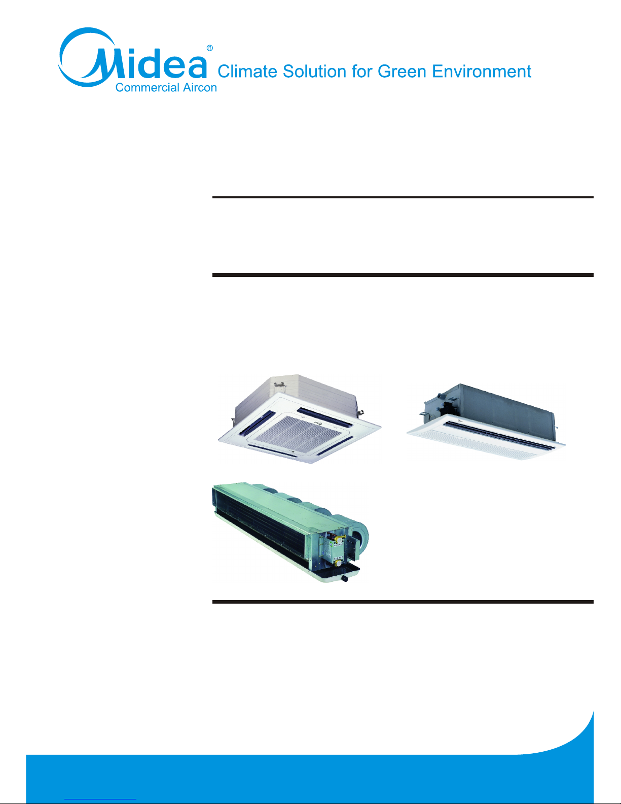
Fan Coil Unit
Cassette and Ceiling Concealed Series

Content MCAC-KTSM-2007-2
i Content
Introduction…………………………………………………………………………………………..1
Part 1 General Information………………………………………………………………………...2
Part 2 Indoor Unit……………………………………………………………………......................7
Part 3 Installation………………………………….……………………………........................127

MCAC-KTSM-2007-2 Introduction
Introduction 1
Introduction
Fan coil unit is a kind of compound device which assemble fan and surface-type coil heating-exchanger
together. Fan coil with fresh air supply system is a main type of center air-conditioner system, so it is an
important component of AC devices. Fan coil has horizontal type, vertical type, etc. A cooling (heating)
supply system usually consists of fan coil terminals and chilled water system (heated water system).
Midea
®
commercial AC fan coil is designed and manufactured on the base of advanced technology, and
utilize qualified galvanized iron as material. Due to its supper-thin design, it has such advantages: beautiful
outlook, space saving, easy installation, etc. And the most obvious advantage is that it can decrease the
outlet air Temp-difference as low as possible to make room more comfortable, as well as don’t decrease
cooling capacity output. For the large air flow volume design, it can increase room ventilation frequency,
supply more flesh air, and balance room temperature distribution. Benefiting from adoption of advanced
material and technology, it can effectively decrease the running noise and keep running smoothly. With the
advantages above, it can be widely applied in market, hospital, office building, hotel airport, etc.

General information MCAC-KTSM-2007-2
2 General Information
Part 1
General Information
1. Model Names of Fan Coil…………......................................3
2. External Appearance……………………………………........4
3. Nomenclature…………………………………………………..5
4. Features…………………………………………….….………..6
MCAC-KTSM-2007-2 Model Names of Fan Coil
General Information 3
1. Model Names of Fan Coil
MKB-300
Compact cassette type fan coil
MKB-400
MKB-450
MKB-500
MKA-600
Cassette type fan coil
MKA-750
MKA-850
MKA-950
MKA-1200
MKA-1500
MKT2(H)-200
2 Rows
Duct type fan coil
MKT2(H)-300
MKT2(H)-400
MKT2(H)-500
MKT2(H)-600
MKT2(H)-800
MKT2(H)-1000
MKT2(H)-1200
MKT2(H)-1400
MKT-300
3 and 4 Rows
MKT-400
MKT-450
MKT-500
MKT-600
MKT-750
MKT-850
MKT-950
MKT-1200
MKT-1500
MKT-2000
MKC-300
One way cassette type fan coil
MKC-400
MKC-600
External Appearance MCAC-KTSM-2007-2
4 General Information
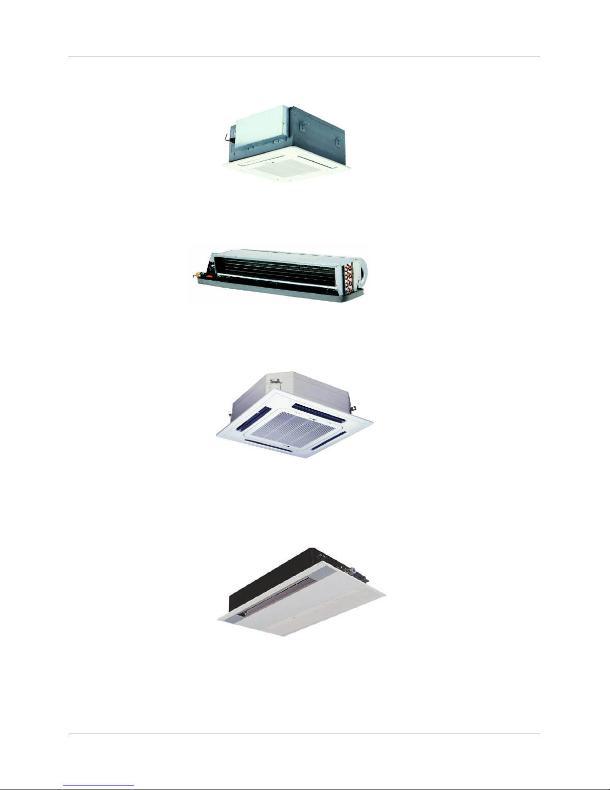
2. External Appearance
Compact four way cassette type
Duct type
Four way cassette type
One way cassette type
MCAC-KTSM-2007-2 Nomenclature
General Information 5
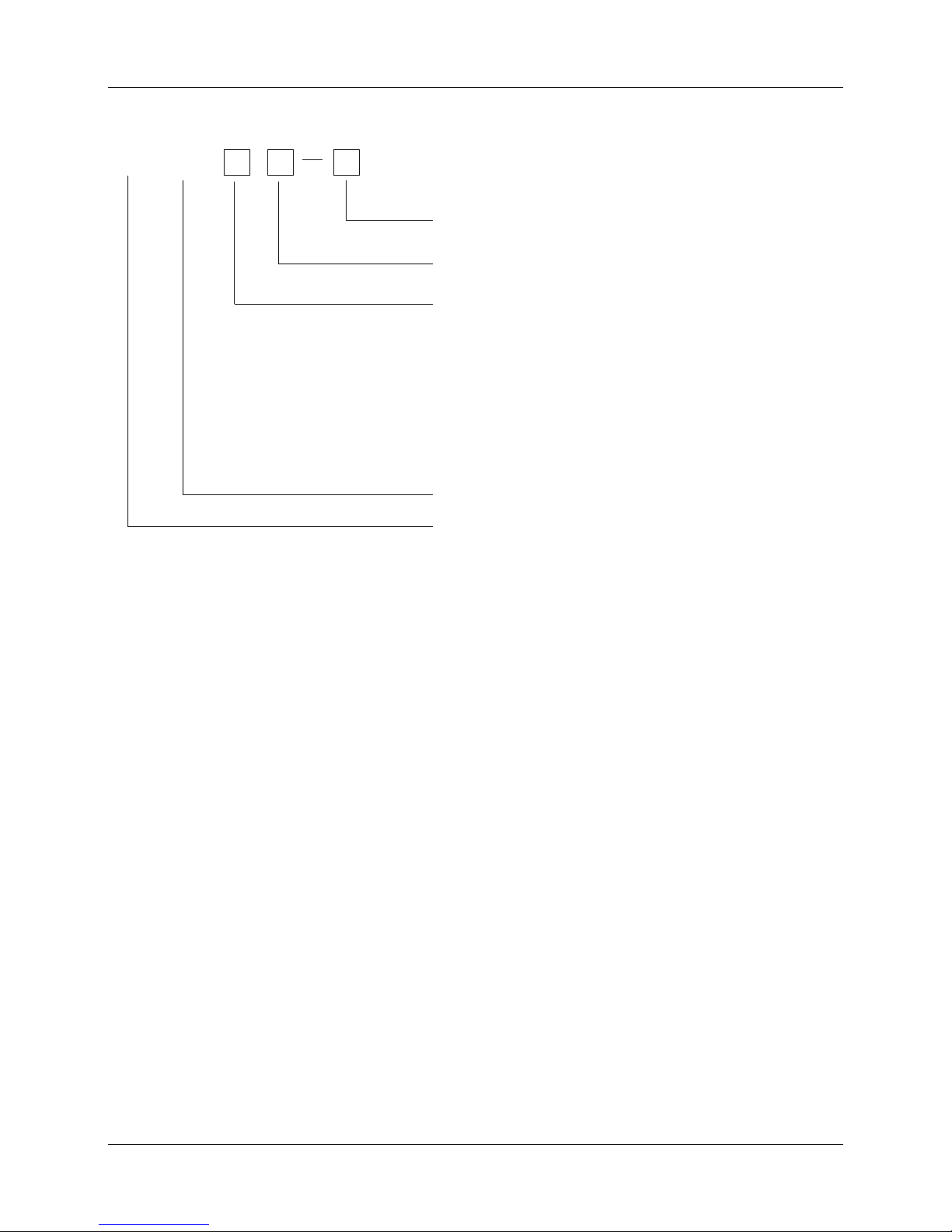
3. Nomenclature
KM
Nominal Air Volume(CFM)
Midea
Chilled Water Fan coil unit
-- 12Pa Static Pressure H 30Pa Static Pressure
F3 Concealed Flood-stand Type
F2 Exposed Flood-stand Type (below air intake)
Type Code
T2 2nd Generation Duct Type
A 4 Way Cassette B 4 Way Cassette (Compact)
C One Way Cassette T Duct
F1 Exposed Floor-stand Type (side air intake)
T1 127v 60 Hz Duct Type

Features MCAC-KTSM-2007-2
6 Indoor Units
4. Features
Chilled water/Hot water (2 pipes)
Low height for easy installation
Low noise fan direct driven by single phase, 3 speed permanent split capacitor motor.
Copper tube/aluminum fin coils
Hydrophilic aluminum fin coils coated (optional)
Unit constructed by electrostatic galvanized sheet, providing maximum protection against corrosion
Heavy gauge zinc coated steel drainage pan with good insulation processing, avoiding sweating and
corrosion
Unit tested performance comply with GB4706.32-2004、JB9063-1999 and JB/T4283-1991.

MCAC-KTSM-2007-2 Indoor Units
Indoor Units 7
Part 2
Indoor Units
Four Way Cassette Type …….................................................6
Compact Four Way Cassette Type.......................................25
Duct Type...............................................................................38
One Way Cassette Type ……..............................................106

Four Way Cassette Type MCAC-KTSM-2007-2
8 Indoor Units
Four Way Cassette Type
1. Features…………………………………….......……………………….............. 9
2. Specification……………………………………………………………............ 10
3. Dimensions………………………………………………………………...........12
4. Service Space……………………………………………………………...........13
5. Wiring Diagrams…………………………………………………………..........14
6. Capacity Tables……………………………………………………………........15
7. Sound Levels……………………………………………………………...........22
8. Explored View……………………………………………………………..........23
MCAC-KTSM-2007-2 Features
Four Way Cassette Type 9
1. Features
(1) Low operation noise
---Streamline plate ensures quietness
---Creates natural and comfortable environment
(2) Efficient cooling
---Equal, fast and wide—range cooling
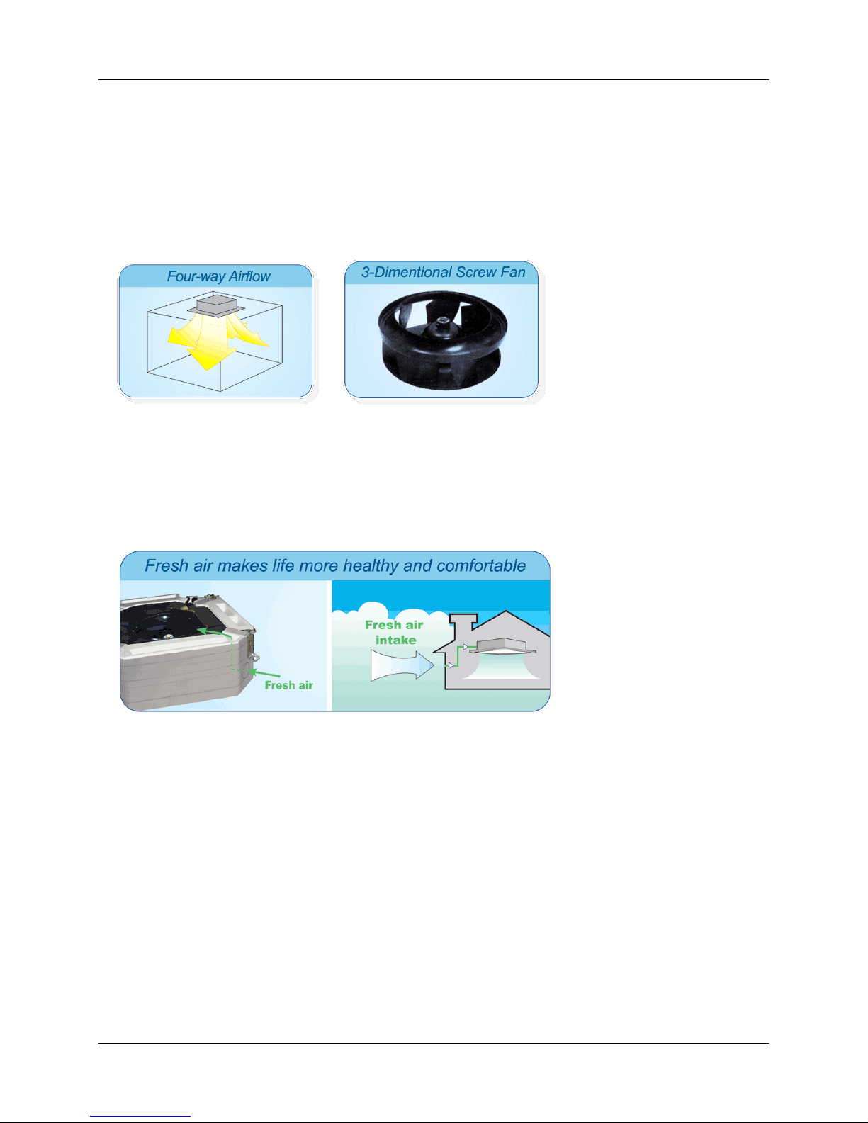
(3) The adoption of the most advanced 3- Dimensional Screw fan
---Reduces the air resistance passing through
---Smoothes the air flow
---Makes air speed distribution to the heat exchange uniform
(4) Fresh air makes life healthier and more comfortable.
Specification MCAC-KTSM-2007-2
10 Four Way Cassette Type
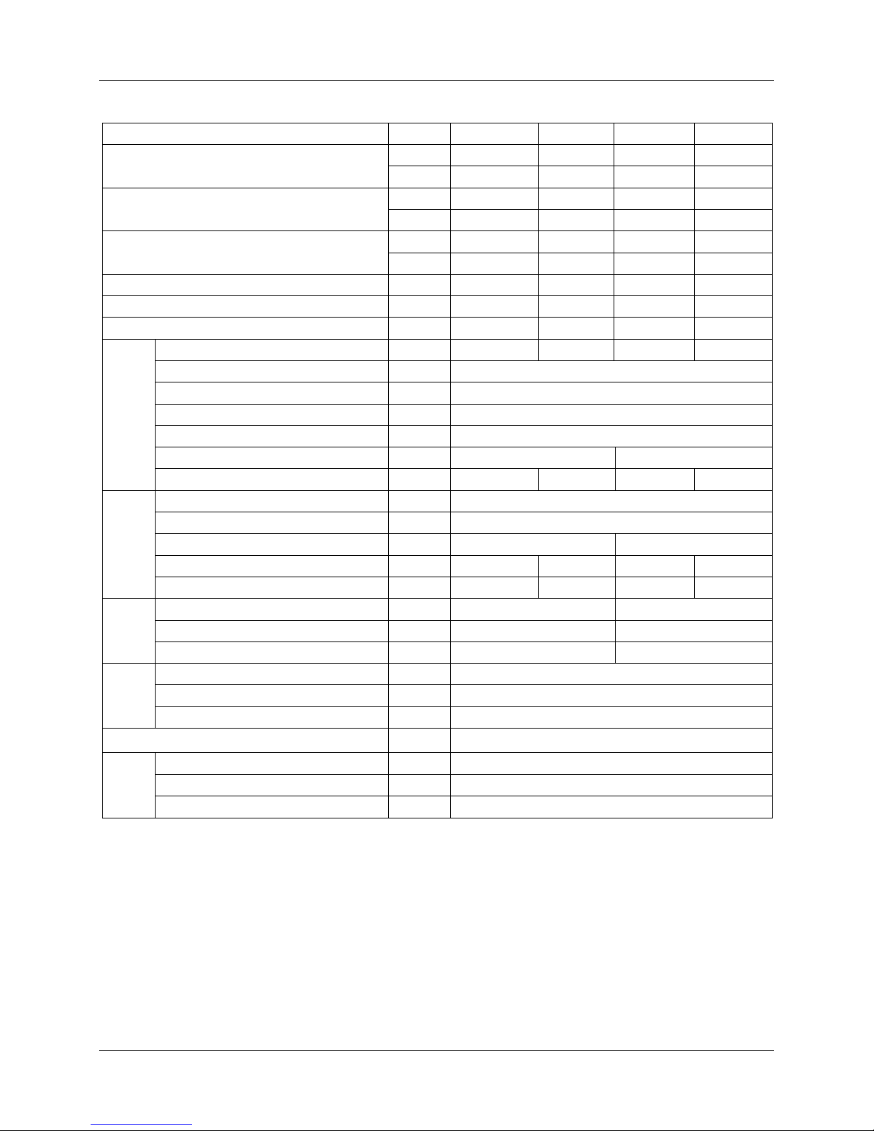
2. Specification
TYPE
MKA-950
MKA-850
MKA-750
MKA-600
Airflow
CFM
950
850
750
600
m3/h
1600
1400
1250
1000
Cooling Capacity
W
8110
7260
6385
5109
Btu/h
27635
24910
21835 17400
Heating Capacity
W
11311
10240
8850
7160
Btu/h
38690
34870
30570
24360
Noise
dB(A)
44
44
41
41
Water flow
LPH
1541
1382
1204
1005
Water resistance
kPa
30
27
25.2
23.8
Indoor
Coil
Number of rows
2 2 2 2
Tube pitch(a)x row pitch(b)
mm
25.4×22
Fin spacing
mm
1.3
Fin type
Hydrophilic aluminum
Tube outside dia.and type
mm
φ7,inner groove tube
Coil length x height x width
mm
2000×250×27
2000×170×27
Number of circuits
6 6 4 4
Fan
motor
Type
Low noise 3 speed fan motor
Number
1 Model YDK56-6
YDK55-6
Input W 144
144
128
120
Capacitor
uF
3.5
3.5
3.5
3.5
Indoor
unit
Dimension (W*H*D)
mm
840×310×840
840×240×840
Packing (W*H*D)
mm
1020×410×930
1020×330×930
Net/Gross weight
kg
40/50
36/46
Panel
Dimension (W*H*D)
mm
950×40×950
Packing (W*H*D)
mm
1030×145×1030
Net/Gross weight
kg
6/11
Control mode
wired controller(optional), remote controller (standard)
Pipe
Water-inlet pipe
RC3/4” internal thread
Water-return pipe RC3/4” internal thread
Condensation water-outlet pipe
EVA+LDPE 3/4” external thread
Remark: 1. All performance data above is based upon 0Pa ambient static pressure.
2. Cooling capacity test condition: air inlet Temp. : 27DB℃/19.5WB℃, water inlet Temp. 7℃,
water Temp. difference 5℃.
3. Heating capacity test condition:
Air inlet Temp. 21DB℃, water inlet Temp. 60 DB℃
The volume of air and water is same as cooling.
4. Noise level is tested in full-anechoic room.
MCAC-KTSM-2007-2 Specifications
Four Way Cassette Type 11
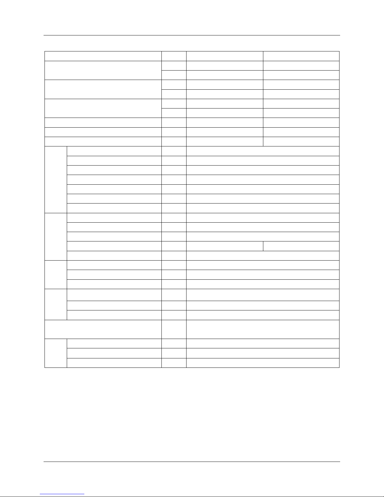
Remark: 1. All performance data above is based upon 0Pa ambient static pressure.
2. Cooling capacity test condition: air inlet Temp. : 27DB℃/19.5WB℃, water inlet Temp. 7℃,
water Temp. difference 5℃.
3. Heating capacity test condition:
Air inlet Temp. 21DB℃, water inlet Temp. 60 DB℃
The volume of air and water is same as cooling.
4. Noise level is tested in full-anechoic room.
TYPE
MKA-1500
MKA-1200
Airflow
CFM
1500
1200
m3/h
2500
2000
Cooling Capacity
W
11556
9849
Btu/h
39240
33440
Heating Capacity
W
14920
13745
Btu/h
51000
46810
Noise
dB(A)
45
45
Water flow
LPH
2388
1928
Water resistance
kPa
46
44
Indoor
Coil
Number of rows
2 Tube pitch(a)x row pitch(b)
mm
25.4×22
Fin spacing
mm
1.3
Fin type
Hydrophilic aluminum
Tube outside dia.and type
mm
φ7,innergroove tube
Coil length x height x width
mm
2000×250×27
Number of circuits
6
Fan
motor
Type
Low noise 3 speed fan motor
Number
1 Model
YDK110-6
Input
W
190
180
Capacitor
uF
5
Indoor
unit
Dimension (W*H*D)
mm
840×310×840
Packing (W*H*D)
mm
1020×410×930
Net/Gross weight
kg
40/50
Panel
Dimension (W*H*D)
mm
950×40×950
Packing (W*H*D)
mm
1030×145×1030
Net/Gross weight
kg
6/11
Control mode
wired controller(optional) ,
remote controller (standard)
Pipe
Water-inlet pipe RC3/4” internal thread
Water-return pipe
RC3/4” internal thread
Condensation water-outlet pipe
EVA+LDPE 3/4” external thread
Dimensions MCAC-KTSM-2007-2
12 Four Way Cassette Type
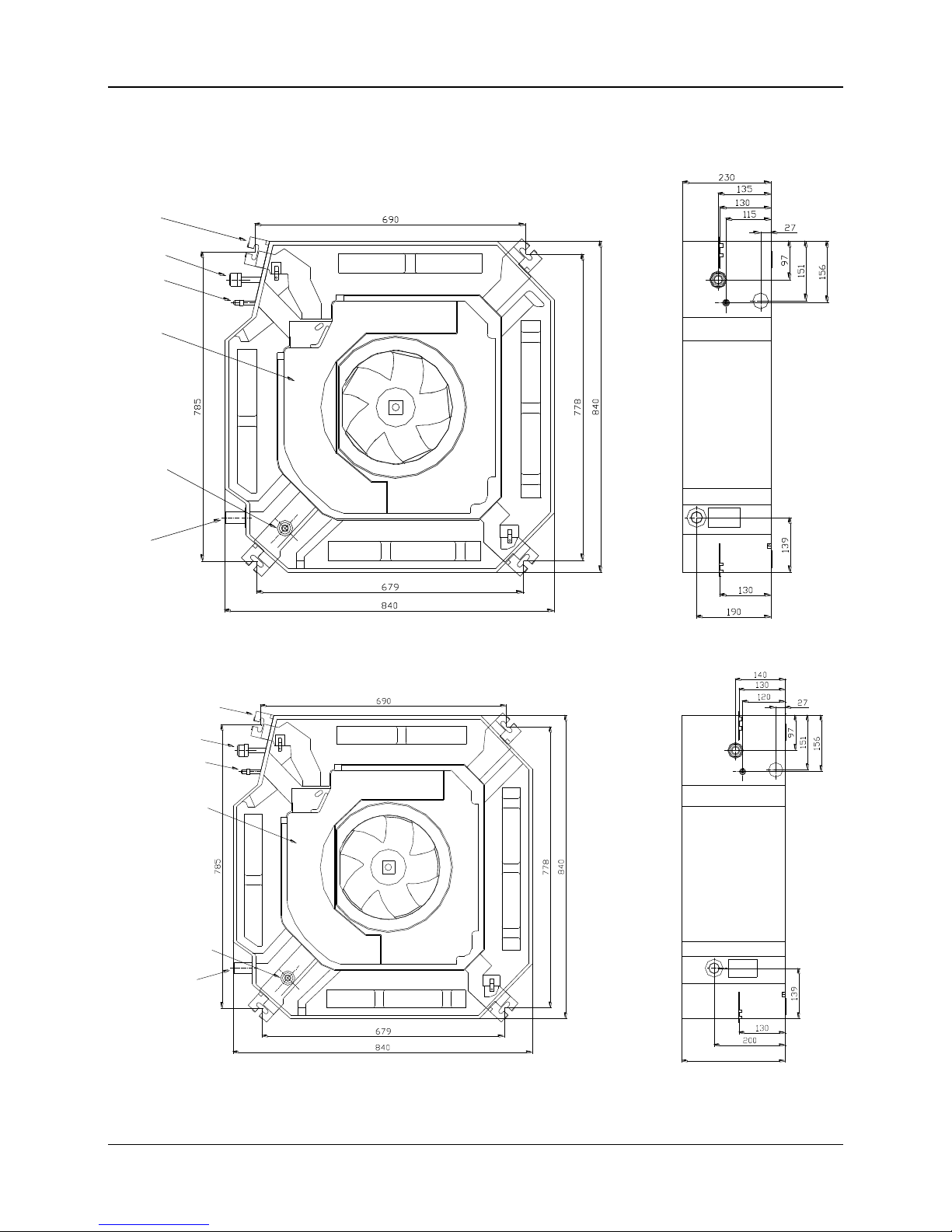
3. Dimensions
MKA-600、MKA-750
Gas side
E-parts box
Liquid side
4-install hanger
Drain hole
Pump
inspect hole
MKA-850、MKA-950、MKA-1200、MKA-1500
310
4-install
hanger
Gas side
liquid side
E-parts box
Pump
inspect hole
Drain hole
MCAC-KTSM-2007-2 Service Space
Four Way Cassette Type 13
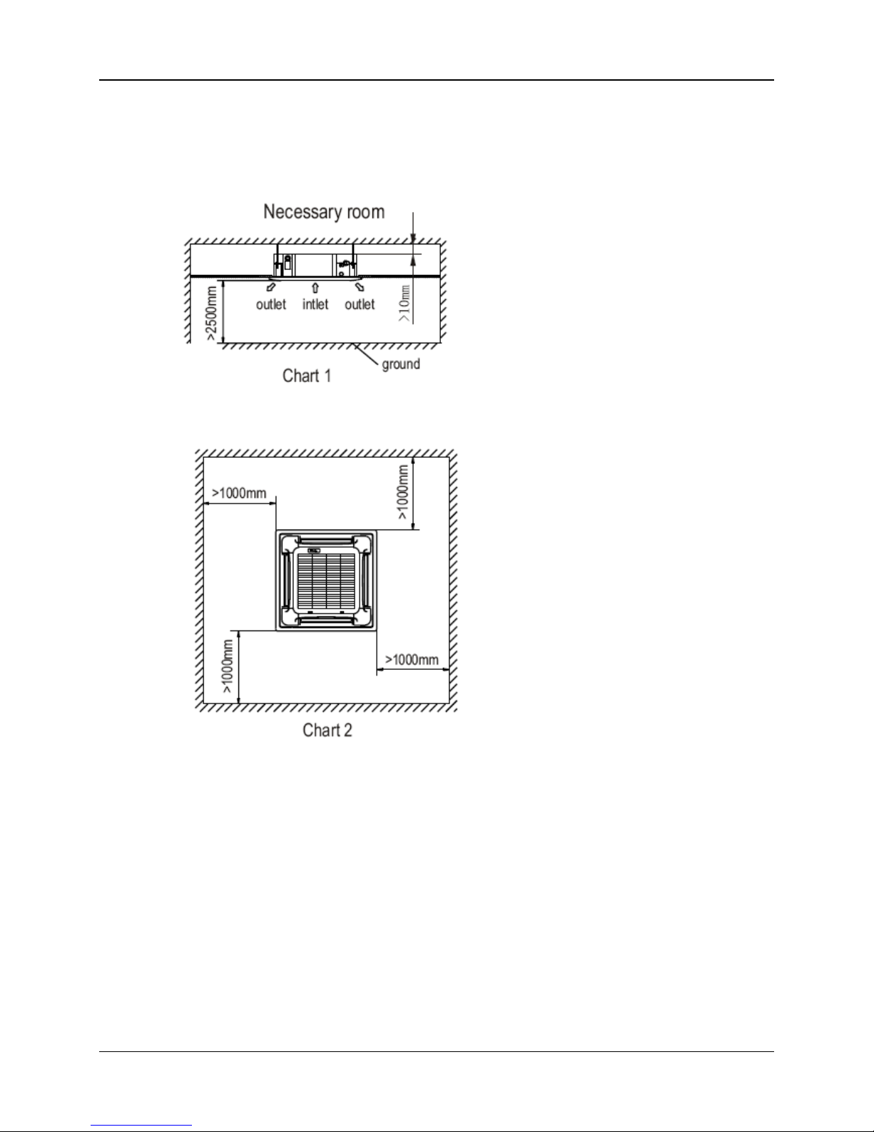
4. Service Spaces
MKA-600、MKA-750、MKA-850、MKA-950、MKA-1200、MKA-1500
Wring Diagram MCAC-KTSM-2007-2
14 Four Way Cassette Type
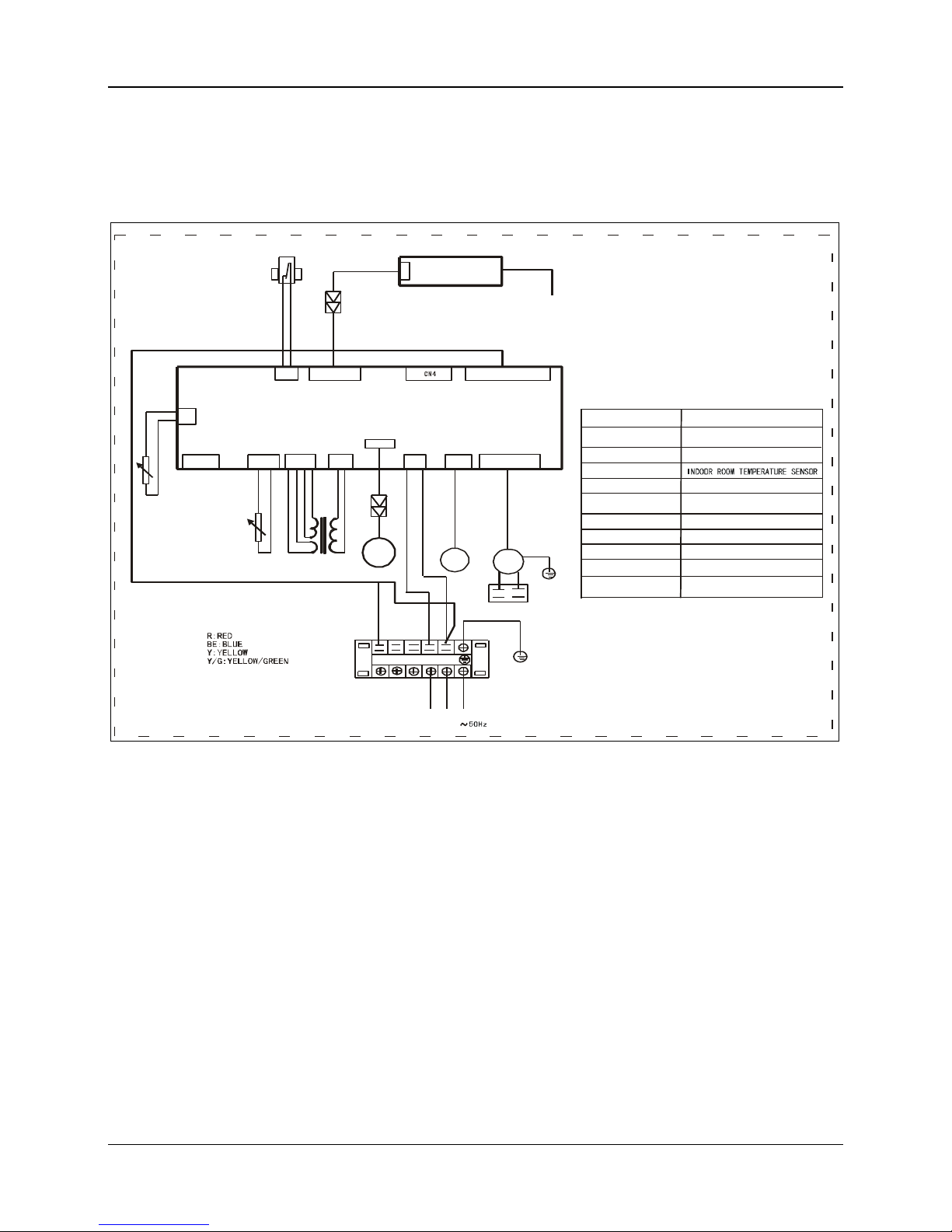
5. Wiring Diagram
MKA-600、MKA-750、MKA-850、MKA-950、MKA-1200、MKA-1500
XS1
XP1
R
POWER:220V-240V
MAINBOARD
XT1
L
T4
K3
INDOOR DRAWING
POWER:220V-240V~
50Hz
FAN1
BE
N
N1L1
PUMP
Y/G
CAP1
Y/G
XS1-XS2
Rt3
XT1
XP1-XP2
T4
K3
Rt2
FAN1
2CON10
DISPLAY
CAP1
CONNECTORS
6-WAY
TERMINAL
TRANSFORMER
PIPE TEMPERATURE SENSOR
PUMP WATER PUMP
CODE
WATER
LEVLE
INDOOR FAN
INDOOR FAN
PART
CAPACITOR
SWITCH
CN8
CN11 CN10
CN5
CN7
CN3
CN2
CN12
CN1 CN14 CN16
CN15
RT2
RT3
M
R Y
XS2
XP2
CONNECTORS
TO WIRE CONTROLER
(CHOICE)
REMARK:

MCAC-KTSM-2007-2 Capacity Tables
Four Way Cassette Type 15
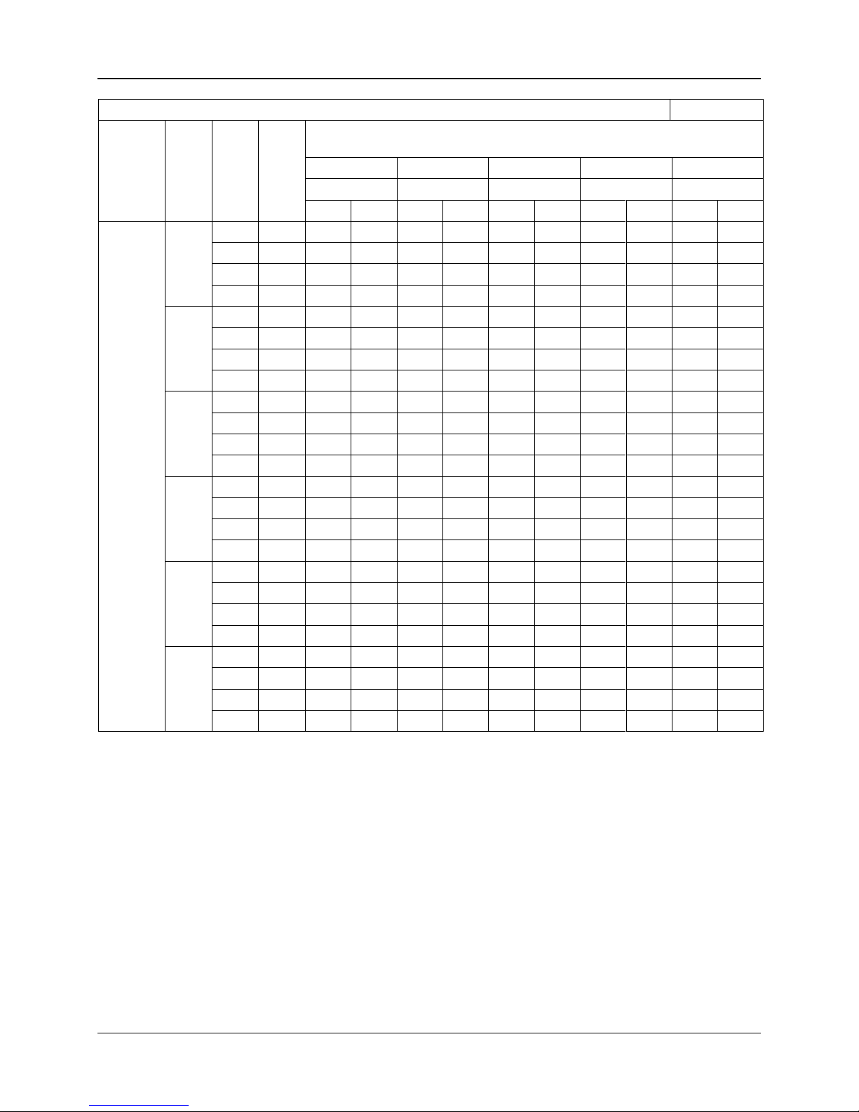
6. Capacity Tables
Cooling Capacity Table
Unit: W
Model
Water
inlet
temp.
(℃)
Water
FV
(LPM)
Water
PD
(kPa)
Air inlet condition
DB24℃
DB25℃
DB26℃
DB27℃
DB28℃
WB17℃
WB18℃
WB19℃
WB19.5℃
WB21℃
SH
TH
SH
TH
SH
TH
SH
TH
SH
TH
MKA-600
5
10
13.5
3439
4047
3537
4449
3636
4860
3823
5074
3823
5717
15
30.4
3716
4735
3850
5217
3975
5708
4172
5958
4207
6736
20
54
3913
5181
4056
5708
4199
6262
4404
6539
4467
7406
25
84.4
4029
5458
4181
6012
4333
6593
4547
6896
4627
7817 6 10
13.5
3296
3734
3404
4127
3502
4538
3689
4744
3689
5387
15
30.4
3555
4368
3689
4842
3815
5333
4011
5583
4047
6352
20
54
3734
4788
3877
6218
4020
5851
4225
6137
4297
6995
25
84.4
3841
5038
3993
5601
4154
6173
4359
6477
4449
7388 7 10
13.5
3162
3413
3270
3806
3368
4208
3555
4413
3564
5047
15
30.4
3395
4002
3529
4467
3654
4958
3850
5100
3895
5967
20
54
3555
4386
3707
4904
3850
5449
4056
5726
4118
6575
25
84.4
3654
4618
3815
5172
3966
5753
4181
6039
4261
6959 8 10
13.5
3028
3082
3136
3475
3234
3877
3421
4083
3430
4717
15
30.4
3243
3627
3368
4091
3502
4574
3698
4815
3743
5574
20
54
3386
3975
3529
4493
3672
5029
3877
5306
3949
6155
25
84.4
3466
4199
3627
4744
3788
5315
3993
5610
4083
6512 9 10
13.5
2894
2894
3002
3145
3109
3547
3296
3743
3305
4368
15
30.4
3082
3243
3216
3707
3341
4181
3538
4431
3591
5181
20
54
3207
3564
3359
4083
3502
4610
3707
4878
3779
5726
25
84.4
3287
3761
3448
4306
3600
4878
3815
5163
3904
6066
10
10
13.5
2760
2760
2877
2877
2975
3207
3162
3404
3180
4029
15
30.4
2930
2930
3064
3314
3189
3788
3386
4029
3439
4779
20
54
3037
3145
3189
3654
3332
4181
3538
4449
3618
5288
25
84.4
3109
3323
3270
3859
3421
4422
3636
4708
3725
5601
Remark:
1. DB: Dry Bulb Temp. WB: Wet Bulb Temp. FV: Flow Volume
TH: Total heat SH: Sensible heat PD: Pressure Drop
2. Table above is based on normal type fan coil high speed air-flow volume; cooling capacity on other speed
air flow volume should multiply with corresponding capacity modification coefficient (refer to capacity
modification coefficient diagram.)
Capacity Tables MCAC -KTSM-2007-2
16 Four Way Cassette Type
Cooling Capacity Table
Unit: W
Model
Water
inlet
temp.
(℃)
Water
FV
(LPM)
Water
PD
(kPa)
Air inlet condition
DB24℃
DB25℃
DB26℃
DB27℃
DB28℃
WB17℃
WB18℃
WB19℃
WB19.5℃
WB21℃
SH
TH
SH
TH
SH
TH
SH
TH
SH
TH
MKA-750
5
15
11.9
4001
4838
4121
5316
4241
5811
4455
6058
4472
6839
20
21.2
4217
5372
4368
5907
4504
6465
4727
6752
4774
7636
25
33.1
4392
5779
4551
6369
4711
6975
4942
7285
5006
8250
30
47.7
4504
6034
4679
6656
4847
7294
5078
7772
5166
8640 6 15
11.9
3834
4455
3962
4934
4081
5421
4296
5676
4313
6448
20
21.2
4041
4950
4185
5492
4328
6042
4551
6448
4592
7206
25
33.1
4193
5333
4360
5922
4519
6520
4742
6831
4815
7787
30
47.7
4296
5580
4472
6193
4639
6831
4879
7158
4958
8162 7 15
11.9
3675
4073
3802
4551
3921
5038
4137
5284
4153
6050
20
21.2
3858
4536
4001
5309
4145
5779
4368
6385
4416
6767
25
33.1
4001
4886
4161
5548
4320
6146
4551
6433
4624
7326
30
47.7
4097
5110
4264
5723
4440
6353
4671
6679
4759
7684 8 15
11.9
3507
3690
3643
4161
3762
4639
3977
4886
4001
5644
20
21.2
3675
4105
3826
4639
3970
5181
4193
5539
4241
6321
25
33.1
3810
4432
3970
5006
4129
5603
4360
5907
4432
6847
30
47.7
3890
4639
4065
5245
4232
5875
4472
6193
4560
7189 9 15
11.9
3356
3356
3484
3762
3611
4241
3826
4487
3842
5237
20
21.2
3499
3675
3651
4200
3794
4742
4017
5022
4073
5875
25
33.1
3611
3970
3778
4543
3938
5134
4169
5436
4249
6369
30
47.7
3690
4161
3866
4759
4033
5380
4273
5699
4360
6688
10
15
11.9
3197
3197
3324
3364
3452
3842
3666
4081
3690
4830
20
21.2
3324
3324
3475
3762
3619
4296
3842
4568
3898
5421
25
33.1
3428
3499
3587
4065
3754
4655
3985
4950
4065
5882
30
47.7
3491
3666
3666
4264
3834
4886
4073
5197
4169
6177
Remark:
1. DB: Dry Bulb Temp. WB: Wet Bulb Temp. FV: Flow Volume
TH: Total heat SH: Sensible heat PD: Pressure Drop
2. Table above is based on normal type fan coil high speed air-flow volume; cooling capacity on other speed
air flow volume should multiply with corresponding capacity modification coefficient (refer to capacity
modification coefficient diagram.)
 Loading...